EP1804116B1 - Color liquid crystal display - Google Patents
Color liquid crystal display Download PDFInfo
- Publication number
- EP1804116B1 EP1804116B1 EP05788185A EP05788185A EP1804116B1 EP 1804116 B1 EP1804116 B1 EP 1804116B1 EP 05788185 A EP05788185 A EP 05788185A EP 05788185 A EP05788185 A EP 05788185A EP 1804116 B1 EP1804116 B1 EP 1804116B1
- Authority
- EP
- European Patent Office
- Prior art keywords
- color
- light
- light source
- liquid crystal
- crystal display
- Prior art date
- Legal status (The legal status is an assumption and is not a legal conclusion. Google has not performed a legal analysis and makes no representation as to the accuracy of the status listed.)
- Not-in-force
Links
- 239000004973 liquid crystal related substance Substances 0.000 title claims abstract description 74
- 230000005540 biological transmission Effects 0.000 claims description 17
- 238000002834 transmittance Methods 0.000 claims description 5
- 230000003595 spectral effect Effects 0.000 description 37
- 238000001228 spectrum Methods 0.000 description 23
- 239000003086 colorant Substances 0.000 description 8
- 230000003287 optical effect Effects 0.000 description 8
- 238000010586 diagram Methods 0.000 description 7
- 239000000758 substrate Substances 0.000 description 6
- 230000005236 sound signal Effects 0.000 description 5
- 230000006870 function Effects 0.000 description 3
- 239000011159 matrix material Substances 0.000 description 3
- 230000001131 transforming effect Effects 0.000 description 3
- 238000005457 optimization Methods 0.000 description 2
- 239000010409 thin film Substances 0.000 description 2
- 241000579895 Chlorostilbon Species 0.000 description 1
- 241000209504 Poaceae Species 0.000 description 1
- 230000002411 adverse Effects 0.000 description 1
- 238000004891 communication Methods 0.000 description 1
- 239000002131 composite material Substances 0.000 description 1
- 238000012937 correction Methods 0.000 description 1
- 230000003247 decreasing effect Effects 0.000 description 1
- 230000000694 effects Effects 0.000 description 1
- 229910052876 emerald Inorganic materials 0.000 description 1
- 239000010976 emerald Substances 0.000 description 1
- 239000010408 film Substances 0.000 description 1
- 239000011521 glass Substances 0.000 description 1
- 150000004820 halides Chemical class 0.000 description 1
- 239000000463 material Substances 0.000 description 1
- 238000012544 monitoring process Methods 0.000 description 1
- 230000000414 obstructive effect Effects 0.000 description 1
- 238000000926 separation method Methods 0.000 description 1
- 230000009466 transformation Effects 0.000 description 1
Images


Classifications
-
- G—PHYSICS
- G02—OPTICS
- G02B—OPTICAL ELEMENTS, SYSTEMS OR APPARATUS
- G02B6/00—Light guides; Structural details of arrangements comprising light guides and other optical elements, e.g. couplings
- G02B6/0001—Light guides; Structural details of arrangements comprising light guides and other optical elements, e.g. couplings specially adapted for lighting devices or systems
- G02B6/0011—Light guides; Structural details of arrangements comprising light guides and other optical elements, e.g. couplings specially adapted for lighting devices or systems the light guides being planar or of plate-like form
- G02B6/0066—Light guides; Structural details of arrangements comprising light guides and other optical elements, e.g. couplings specially adapted for lighting devices or systems the light guides being planar or of plate-like form characterised by the light source being coupled to the light guide
- G02B6/0068—Arrangements of plural sources, e.g. multi-colour light sources
-
- G—PHYSICS
- G02—OPTICS
- G02F—OPTICAL DEVICES OR ARRANGEMENTS FOR THE CONTROL OF LIGHT BY MODIFICATION OF THE OPTICAL PROPERTIES OF THE MEDIA OF THE ELEMENTS INVOLVED THEREIN; NON-LINEAR OPTICS; FREQUENCY-CHANGING OF LIGHT; OPTICAL LOGIC ELEMENTS; OPTICAL ANALOGUE/DIGITAL CONVERTERS
- G02F1/00—Devices or arrangements for the control of the intensity, colour, phase, polarisation or direction of light arriving from an independent light source, e.g. switching, gating or modulating; Non-linear optics
- G02F1/01—Devices or arrangements for the control of the intensity, colour, phase, polarisation or direction of light arriving from an independent light source, e.g. switching, gating or modulating; Non-linear optics for the control of the intensity, phase, polarisation or colour
- G02F1/13—Devices or arrangements for the control of the intensity, colour, phase, polarisation or direction of light arriving from an independent light source, e.g. switching, gating or modulating; Non-linear optics for the control of the intensity, phase, polarisation or colour based on liquid crystals, e.g. single liquid crystal display cells
- G02F1/133—Constructional arrangements; Operation of liquid crystal cells; Circuit arrangements
- G02F1/1333—Constructional arrangements; Manufacturing methods
- G02F1/1335—Structural association of cells with optical devices, e.g. polarisers or reflectors
- G02F1/133509—Filters, e.g. light shielding masks
- G02F1/133514—Colour filters
-
- G—PHYSICS
- G02—OPTICS
- G02F—OPTICAL DEVICES OR ARRANGEMENTS FOR THE CONTROL OF LIGHT BY MODIFICATION OF THE OPTICAL PROPERTIES OF THE MEDIA OF THE ELEMENTS INVOLVED THEREIN; NON-LINEAR OPTICS; FREQUENCY-CHANGING OF LIGHT; OPTICAL LOGIC ELEMENTS; OPTICAL ANALOGUE/DIGITAL CONVERTERS
- G02F1/00—Devices or arrangements for the control of the intensity, colour, phase, polarisation or direction of light arriving from an independent light source, e.g. switching, gating or modulating; Non-linear optics
- G02F1/01—Devices or arrangements for the control of the intensity, colour, phase, polarisation or direction of light arriving from an independent light source, e.g. switching, gating or modulating; Non-linear optics for the control of the intensity, phase, polarisation or colour
- G02F1/13—Devices or arrangements for the control of the intensity, colour, phase, polarisation or direction of light arriving from an independent light source, e.g. switching, gating or modulating; Non-linear optics for the control of the intensity, phase, polarisation or colour based on liquid crystals, e.g. single liquid crystal display cells
- G02F1/133—Constructional arrangements; Operation of liquid crystal cells; Circuit arrangements
- G02F1/1333—Constructional arrangements; Manufacturing methods
- G02F1/1335—Structural association of cells with optical devices, e.g. polarisers or reflectors
- G02F1/1336—Illuminating devices
- G02F1/133602—Direct backlight
- G02F1/133603—Direct backlight with LEDs
-
- G—PHYSICS
- G02—OPTICS
- G02F—OPTICAL DEVICES OR ARRANGEMENTS FOR THE CONTROL OF LIGHT BY MODIFICATION OF THE OPTICAL PROPERTIES OF THE MEDIA OF THE ELEMENTS INVOLVED THEREIN; NON-LINEAR OPTICS; FREQUENCY-CHANGING OF LIGHT; OPTICAL LOGIC ELEMENTS; OPTICAL ANALOGUE/DIGITAL CONVERTERS
- G02F1/00—Devices or arrangements for the control of the intensity, colour, phase, polarisation or direction of light arriving from an independent light source, e.g. switching, gating or modulating; Non-linear optics
- G02F1/01—Devices or arrangements for the control of the intensity, colour, phase, polarisation or direction of light arriving from an independent light source, e.g. switching, gating or modulating; Non-linear optics for the control of the intensity, phase, polarisation or colour
- G02F1/13—Devices or arrangements for the control of the intensity, colour, phase, polarisation or direction of light arriving from an independent light source, e.g. switching, gating or modulating; Non-linear optics for the control of the intensity, phase, polarisation or colour based on liquid crystals, e.g. single liquid crystal display cells
- G02F1/133—Constructional arrangements; Operation of liquid crystal cells; Circuit arrangements
- G02F1/1333—Constructional arrangements; Manufacturing methods
- G02F1/1335—Structural association of cells with optical devices, e.g. polarisers or reflectors
- G02F1/1336—Illuminating devices
- G02F1/133602—Direct backlight
- G02F1/133604—Direct backlight with lamps
-
- G—PHYSICS
- G02—OPTICS
- G02F—OPTICAL DEVICES OR ARRANGEMENTS FOR THE CONTROL OF LIGHT BY MODIFICATION OF THE OPTICAL PROPERTIES OF THE MEDIA OF THE ELEMENTS INVOLVED THEREIN; NON-LINEAR OPTICS; FREQUENCY-CHANGING OF LIGHT; OPTICAL LOGIC ELEMENTS; OPTICAL ANALOGUE/DIGITAL CONVERTERS
- G02F1/00—Devices or arrangements for the control of the intensity, colour, phase, polarisation or direction of light arriving from an independent light source, e.g. switching, gating or modulating; Non-linear optics
- G02F1/01—Devices or arrangements for the control of the intensity, colour, phase, polarisation or direction of light arriving from an independent light source, e.g. switching, gating or modulating; Non-linear optics for the control of the intensity, phase, polarisation or colour
- G02F1/13—Devices or arrangements for the control of the intensity, colour, phase, polarisation or direction of light arriving from an independent light source, e.g. switching, gating or modulating; Non-linear optics for the control of the intensity, phase, polarisation or colour based on liquid crystals, e.g. single liquid crystal display cells
- G02F1/133—Constructional arrangements; Operation of liquid crystal cells; Circuit arrangements
- G02F1/1333—Constructional arrangements; Manufacturing methods
- G02F1/1335—Structural association of cells with optical devices, e.g. polarisers or reflectors
- G02F1/1336—Illuminating devices
- G02F1/133602—Direct backlight
- G02F1/133609—Direct backlight including means for improving the color mixing, e.g. white
-
- G—PHYSICS
- G09—EDUCATION; CRYPTOGRAPHY; DISPLAY; ADVERTISING; SEALS
- G09G—ARRANGEMENTS OR CIRCUITS FOR CONTROL OF INDICATING DEVICES USING STATIC MEANS TO PRESENT VARIABLE INFORMATION
- G09G3/00—Control arrangements or circuits, of interest only in connection with visual indicators other than cathode-ray tubes
- G09G3/20—Control arrangements or circuits, of interest only in connection with visual indicators other than cathode-ray tubes for presentation of an assembly of a number of characters, e.g. a page, by composing the assembly by combination of individual elements arranged in a matrix no fixed position being assigned to or needed to be assigned to the individual characters or partial characters
- G09G3/34—Control arrangements or circuits, of interest only in connection with visual indicators other than cathode-ray tubes for presentation of an assembly of a number of characters, e.g. a page, by composing the assembly by combination of individual elements arranged in a matrix no fixed position being assigned to or needed to be assigned to the individual characters or partial characters by control of light from an independent source
- G09G3/3406—Control of illumination source
- G09G3/3413—Details of control of colour illumination sources
-
- F—MECHANICAL ENGINEERING; LIGHTING; HEATING; WEAPONS; BLASTING
- F21—LIGHTING
- F21Y—INDEXING SCHEME ASSOCIATED WITH SUBCLASSES F21K, F21L, F21S and F21V, RELATING TO THE FORM OR THE KIND OF THE LIGHT SOURCES OR OF THE COLOUR OF THE LIGHT EMITTED
- F21Y2113/00—Combination of light sources
- F21Y2113/20—Combination of light sources of different form
-
- G—PHYSICS
- G02—OPTICS
- G02B—OPTICAL ELEMENTS, SYSTEMS OR APPARATUS
- G02B5/00—Optical elements other than lenses
- G02B5/20—Filters
- G02B5/22—Absorbing filters
- G02B5/223—Absorbing filters containing organic substances, e.g. dyes, inks or pigments
-
- G—PHYSICS
- G02—OPTICS
- G02B—OPTICAL ELEMENTS, SYSTEMS OR APPARATUS
- G02B6/00—Light guides; Structural details of arrangements comprising light guides and other optical elements, e.g. couplings
- G02B6/0001—Light guides; Structural details of arrangements comprising light guides and other optical elements, e.g. couplings specially adapted for lighting devices or systems
- G02B6/0011—Light guides; Structural details of arrangements comprising light guides and other optical elements, e.g. couplings specially adapted for lighting devices or systems the light guides being planar or of plate-like form
- G02B6/0066—Light guides; Structural details of arrangements comprising light guides and other optical elements, e.g. couplings specially adapted for lighting devices or systems the light guides being planar or of plate-like form characterised by the light source being coupled to the light guide
- G02B6/0073—Light emitting diode [LED]
-
- G—PHYSICS
- G02—OPTICS
- G02F—OPTICAL DEVICES OR ARRANGEMENTS FOR THE CONTROL OF LIGHT BY MODIFICATION OF THE OPTICAL PROPERTIES OF THE MEDIA OF THE ELEMENTS INVOLVED THEREIN; NON-LINEAR OPTICS; FREQUENCY-CHANGING OF LIGHT; OPTICAL LOGIC ELEMENTS; OPTICAL ANALOGUE/DIGITAL CONVERTERS
- G02F1/00—Devices or arrangements for the control of the intensity, colour, phase, polarisation or direction of light arriving from an independent light source, e.g. switching, gating or modulating; Non-linear optics
- G02F1/01—Devices or arrangements for the control of the intensity, colour, phase, polarisation or direction of light arriving from an independent light source, e.g. switching, gating or modulating; Non-linear optics for the control of the intensity, phase, polarisation or colour
- G02F1/13—Devices or arrangements for the control of the intensity, colour, phase, polarisation or direction of light arriving from an independent light source, e.g. switching, gating or modulating; Non-linear optics for the control of the intensity, phase, polarisation or colour based on liquid crystals, e.g. single liquid crystal display cells
- G02F1/133—Constructional arrangements; Operation of liquid crystal cells; Circuit arrangements
- G02F1/1333—Constructional arrangements; Manufacturing methods
- G02F1/1335—Structural association of cells with optical devices, e.g. polarisers or reflectors
- G02F1/1336—Illuminating devices
- G02F1/133624—Illuminating devices characterised by their spectral emissions
-
- G—PHYSICS
- G09—EDUCATION; CRYPTOGRAPHY; DISPLAY; ADVERTISING; SEALS
- G09G—ARRANGEMENTS OR CIRCUITS FOR CONTROL OF INDICATING DEVICES USING STATIC MEANS TO PRESENT VARIABLE INFORMATION
- G09G2320/00—Control of display operating conditions
- G09G2320/06—Adjustment of display parameters
- G09G2320/0666—Adjustment of display parameters for control of colour parameters, e.g. colour temperature
-
- G—PHYSICS
- G09—EDUCATION; CRYPTOGRAPHY; DISPLAY; ADVERTISING; SEALS
- G09G—ARRANGEMENTS OR CIRCUITS FOR CONTROL OF INDICATING DEVICES USING STATIC MEANS TO PRESENT VARIABLE INFORMATION
- G09G2360/00—Aspects of the architecture of display systems
- G09G2360/18—Use of a frame buffer in a display terminal, inclusive of the display panel
Definitions
- This invention relates to a color liquid crystal display (LCD) apparatus and, more particularly, to a color liquid crystal display apparatus with which the color gamut can be made broader to assure more faithful color reproducing performance.
- LCD color liquid crystal display
- a picture unit receiving and displaying the color information, captured by a camera or a scanner, such as a display or a printer, it is essential to demonstrate the received color information accurately. For example, if a camera has captured the color information accurately, but a display demonstrates the color information only inappropriately, color reproduction performance of the system on the whole is deteriorated.
- the display In a current standard monitor device, the display is prescribed by the color gamut of the sRGB standard. In actuality, there are many colors beyond the color gamut of sRGB, such that there are object colors that cannot be represented by a standard monitor device complying with the sRGB standard.
- the range of sRGB has already been exceeded. If the broad dynamic range is procured, and an image pickup operation is carried out correctly, there are produced object colors that cannot be represented on a standard monitor device of the sRGB standard.
- the sYCC having a color space broader than that of sRGB, has been adopted as a standard by business circles, in order to cope with the color gamut which has become broader.
- the sYCC has derived, from the sRGB, the luminance difference color difference separation space, using ITU-R BT.601, which is the international standard of a transformation matrix from RGB to YCC as defined for high vision television.
- the color gamut of sYCC is broader as the color space than the sRGB, such that, with the sYCC, the color outside sRGB can be represented.
- the bandwidth is broader than in sRGB. If sYCC is to be implemented, the color gamut on the display with sYCC needs to be equivalent to or even exceed that of the NTSC system.
- a TV receiver of an extremely thin thickness such as one employing a liquid crystal display (LCD) or a plasma display panel (PDP)
- LCD liquid crystal display
- PDP plasma display panel
- CRT cathode ray tube
- a color liquid crystal display apparatus employing a color liquid crystal display panel is expected to become popular in an accelerated manner because it permits driving with low power consumption and the large-sized color liquid crystal display panel has become less expensive.
- the backlight system in which a transmissive color liquid crystal display panel is illuminated from its backside with a backlight device to display a color picture, is in the mainstream.
- the light source is a CCFL (Cold Cathode Fluorescent Lamp), emitting white light using a fluorescent tube.
- a color filter employing a tristimulus filter or a three prime color filter of spectral characteristics, shown for example in Fig.1 , made up of a blue filter CFB 0 (460 nm), a green filter CFG 0 (530 nm) and a red filter CFR 0 (685 nm), where the numbers entered in parentheses denote the peak transmission wavelength of each filter, is provided from one pixel of the color liquid crystal display panel to another.
- the white light, emitted by a three-wavelength CCFL, used as a light source for a backlight device of the color liquid crystal display apparatus has a spectrum shown in Fig.1 . That is, the white light emitted by the CCFL contains light of different intensities in a variety of wavelengths. Hence, the color reproduced by the combination of the backlight device, having such CCFL, emitting the light of three wavelength ranges, as light source, and the color liquid crystal display panel, having the color filter, described above, is rather poor in color purity.
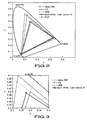
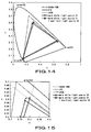
- Fig.2 shows the color reproducing range of the color liquid crystal display apparatus, including the backlight device, having the above-described three-wavelength CCFL as a light source.
- Fig.2 depicts an xy chromaticity diagram of the XYZ color system, as prescribed by the Commission Internationale de l'Eclairage (CIE).
- CIE Commission Internationale de l'Eclairage
- Fig.2 there is also shown a color reproducing range of the Adobe RGB standard which is the standard for the color reproducing range as used in Photoshop, an application software prepared by the Adobe System Inc.
- the Adobe RGB standard providing a color reproducing range broader than one of the sRGB standard, is not an international standard of reference, however, it is recognized as a de-facto standard for business uses, such as printing/publication.
- This Adobe RGB standard has come into extensive use with increase in a demand for monitoring color reproduction of printed matter using a large format display.
- the color reproducing range of the color liquid crystal display apparatus is adapted to comply with the sRGB standard.
- a color liquid crystal display panel is illuminated with a backlight device, having the CCFL as a light source, the color reproducing range of the sRGB standard is not satisfied, insofar as the green (G) region is concerned, given the luminance spectrum of the CCFL shown in Fig.1 .
- the green (G), blue (B) and red (R) regions, shown in Fig.2 are shown to an enlarged scale, respectively.
- the color reproducing range of the color liquid crystal display apparatus provided with a backlight device, having the CCFL as a light source, is narrower than the color reproducing range as provided for by the standard of the NTSC (National Television System Committee) system, as adopted as a color television broadcasting system (NTSC ratio: 74%), and hence cannot cope sufficiently with the current television broadcasting.
- NTSC National Television System Committee
- the document JP 2003 331 608 A discloses a liquid crystal display device with CCFLs and LEDs.
- the present invention provides a color liquid crystal display apparatus including a transmissive color liquid crystal display panel, having a color filter made up of three prime color filters for wavelength selecting and transmitting red light, green light and blue light, and a backlight device for illuminating the color liquid crystal display panel with white light from its backside.
- the backlight device includes a main white light source having a three wavelength phosphorescent lamp emitting light with three or more wavelengths, and an auxiliary light source having at least one of a red light emitting diode, a green light emitting diode and a blue light emitting diode.
- the backlight device also includes color mixing means for mixing the light emitted from the light source to generate the white light.
- a main white light source having a three wavelength phosphorescent lamp, emitting light with three or more wavelengths, and an auxiliary light source having at least one of a red light emitting diode, a green light emitting diode and a blue light emitting diode are used as light sources of the backlight device.
- the color filter includes a red color filter having a peak wavelength of a transmission wavelength range Fpr such that 685nm ⁇ Fpr ⁇ 690 nm, and having a zero transmittance for light included in a transmission wavelength range of a blue filter.
- the color filter also includes a green filter having a peak wavelength of a transmission wavelength range Fpg equal to 530 nm, and also having a half-value width Fhwg of the transmission wavelength range such that 90 nm ⁇ Fhwg ⁇ 100 nm, as a result of decreasing the transmittance of the green filter for light included in the transmission wavelength range of the blue filter, and the blue filter having a peak wavelength of a transmission wavelength Fpb such that 440 nm ⁇ Fpb ⁇ 460 nm.
- the characteristics of the red filter, green filter and the blue filter, provided on the color liquid crystal display panel are matched to those of the light source, composed of the main white light source and the auxiliary light source, provided on the backlight device, by way of optimization, thereby enlarging the color reproducing range of a picture displayed on the color liquid crystal display apparatus.
- the present invention is applied to a color liquid crystal display apparatus 100 of the backlight system, configured as shown for example in Fig.6 .
- the transmissive color liquid crystal display apparatus 100 is made up of a transmissive color liquid crystal display panel 10, and a backlight unit 40, provided on the backside of this color liquid crystal display panel 10.
- This transmissive color liquid crystal display apparatus 100 may be provided with a receiving unit, such as an analog tuner or a digital tuner, not shown, for receiving the ground wave or the satellite wave, and a picture signal processing unit or an audio signal processing unit, also not shown, for processing picture signals or audio signals, received by this receiving unit, respectively.
- the color liquid crystal display apparatus may also be provided with an audio signal outputting unit, again not shown, such as loudspeaker, for outputting audio signals processed by the audio signal processing unit.
- the transmissive color liquid crystal display panel 10 is made up of two transparent substrates, formed by glass or the like (a TFT substrate 11 and a counter-electrode substrate 12), facing each other, and a liquid crystal layer 13 of, for example, twisted nematic (TN) liquid crystal, enclosed in a space between the two substrates.
- a TFT substrate 11 and a counter-electrode substrate 12 facing each other, and a liquid crystal layer 13 of, for example, twisted nematic (TN) liquid crystal, enclosed in a space between the two substrates.
- signal lines 14 and scanning lines 15 arranged in a matrix configuration, as well as thin-film transistors 16, as switching elements, and pixel electrodes 17, arranged at the points of intersection of the signal lines 14 and the scanning lines 15.
- the thin-film transistors 16 are sequentially selected by the scanning lines 15 to write picture signals, supplied from the signal lines 14, in the associated pixel electrodes 17.
- the color filter 19 is divided into a plural number of segments associated with a pixel.
- the color filter is divided into three segments, associated with three prime colors, that is, a red filter CFR, a green filter CFG and a blue filter CFB, as shown in Fig.7 .
- the arraying pattern for the color filter may be exemplified by delta array or square array, not shown, in addition to the striped array shown in Fig.7 .
- the color filter 19 will be described in detail subsequently.
- the transmissive color liquid crystal display panel 10 is sandwiched between a pair of polarizing plates 31, 32, and driven in accordance with an active matrix system, as white light is illuminated from its backside by the backlight unit 40, thereby displaying a desired full-color picture.
- the backlight unit 40 illuminates the color liquid crystal display panel 10 from its backside.
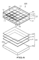
- the backlight unit 40 includes a backlight device 20, and a set of optical sheets, stacked on a light radiating surface 20a of the backlight device 20, such as a light diffusing sheet 41, a prism sheet 42 and a polarized light transforming sheet 43.
- the backlight device 20 includes plural light sources and mixes the light from the light sources to generate white light which is radiated by surface light emission from the light radiating surface 20a.
- the set of optical sheets is made up of a plural number of sheets having the functions of resolving the incident light into mutually perpendicular polarized components, compensating the phase difference of light waves to assure a broad angle of visibility and of preventing coloration, diffusing the incident light or improving the luminance.
- the set of optical sheets is provided for transforming the light, radiated by surface light emission from the backlight device 20, into illuminating light having optimum optical characteristics for illuminating the color liquid crystal display panel 10.
- the set of optical sheets may include not only the light diffusing sheet 41, prism sheet 42 or polarized light transforming sheet 43, but a variety of other optical sheets having a variety of other optical functions.
- the white light, generated on color mixing by the backlight device 20, is illuminated to the color liquid crystal display panel 10 from its backside via the set of optical sheets described above.
- the color liquid crystal display apparatus 100 is driven by a driving circuit 200 shown for example in Fig.8 .
- This driving circuit 200 includes a power supply unit 110 for supplying driving supply power for e.g. the color liquid crystal display panel 10 and the backlight device 20, and an X-driver circuit 120 as well as a Y-driver circuit 130 for driving the color liquid crystal display panel 10.
- the driving circuit also includes an RGB processor 150, supplied via an input terminal 140 with picture signals received by a receiver, not shown, of the color liquid crystal display apparatus 100, and which are processed by a picture signal processor.
- the driving circuit also includes a picture memory 160 and a controller 170, both connected to the RGB processor 150, and a backlight driving controller 180 for driving controlling the backlight device 20 of the backlight unit 40.
- the picture signals, transmitted as input via input terminal 140 are subjected to, for example, chroma processing, by the RGB processor 150, and are converted from the composite signals into RGB separate signals, suitable for driving the color liquid crystal display panel 10.
- the resulting signals are transmitted to the controller 170, while being transmitted via picture memory 160 to the X-driver circuit 120.
- the controller 170 controls the X-driver circuit 120 and the Y-driver circuit 130, at a preset timing, matched to the RGB separate signals, in order to drive the color liquid crystal display panel 10 by the RGB separate signals, supplied via picture memory 160 to the X-driver circuit 120, thereby displaying a picture corresponding to the RGB separate signals.
- the backlight driving controller 180 suitably applies the voltage, supplied from the power supply 110, to control the light sources of the backlight device 20.
- a user interface 300 is an interface for selecting a channel received by the aforementioned receiving unit, not shown, adjusting the volume of audio output from an audio output unit, not shown, and for adjusting the white balance or the luminance of white light from the backlight device 20 adapted for illuminating the color liquid crystal display panel 10.
- the CCFL is used as a light source for the backlight device, the color reproducing range of the sRGB standard cannot be covered perfectly, as explained already with reference to Fig.2 .
- the color reproducing range of the CCFL covers the color reproducing range of the sRGB standard, in the blue (B) region and in the red (R) region, however, it fails to cover the color reproducing range of the sRGB standard in the green (G) region, as shown in Figs.3 to 5 .
- the color ranges for the blue (B) region and for the red (R) region exceed the color reproducing range of the sRGB standard, as shown in Figs.4 and 5 , those color ranges cannot be said to be broad enough to increase the degree of freedom in color creation.
- the color range of the green (G) region of the CCFL is offset from the green (G) region of the sRGB standard in a direction towards the blue to green color.
- the color filter used needs to be improved, at least in the green (G) region, shown in Fig.3 , so as to give the chromaticity satisfying the sRGB standard. Moreover, the color ranges of the blue (B) region and the red (R) region, shown in Figs.4 and 5 , are desirably enlarged further from the perspective of color reproduction.
- the bright line spectrum of the CCFL is determined by the three wavelength phosphorescent materials applied on the inner surface of the light emitting tube of the CCFL, it is rather difficult to change the light emitting wavelength of the CCFL.
- a main white light source 21, made up of a CCFL, and an auxiliary light source 22, operating as an assistant for reducing the adverse effect of the bright line spectrum of the main white light source 21, are used as light sources for the backlight device 20.
- the auxiliary light source 22 includes at least one of the red light emitting diode 22R, a green light emitting diode 22G and a blue light emitting diode 22B.
- the backlight device 20 of the color liquid crystal display apparatus 100 includes the main white light source 21 of an area-lit system, made up by a plural number of three-wavelength light emitting phosphorescent lamps (CCFLs) 21F, arranged parallel to one another, and the auxiliary light source 22 of the edge-lit system.
- This auxiliary light source 22 is made up by repetitions of red light emitting diodes 22R, green light emitting diodes 22G and blue light emitting diodes 22B, arranged on a lateral side of a light guide plate 24.
- the major surface of the light guide plate 24 is arranged on the main white light source 21.
- Figs.9 and 10 are a plan view and a longitudinal cross-sectional view, respectively, showing the essential portions of the backlight device 20.
- the diverter plate has the function of mixing the white light, radiated from the main white light source 21, and various color light beams, radiated from the light emitting diodes 21, as the auxiliary light source 22, into white light free of uneven colors.
- the light diffusing plate performs the role of internally diffusing the white light, radiated from the diverter plate, by planar light emission.
- Example 1 peak wavelengths of a red light emitting diode 22R, a green light emitting diode 22G and a blue light emitting diode 22B, making up the auxiliary light source 22, are optimally selected so that the auxiliary light source will act as an assistant for the main white light source 21, in such a manner that the color gamut will be broader, as the color reproducing range of the color liquid crystal display apparatus 100 completely covers that of the sRGB standard.
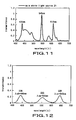
- Fig.11 shows spectral characteristics of a CCFL 21F used as the main white light source 21 of the backlight device 20. It may be seen from Fig.11 that the CCFL 21F, used as the main white light source 21, has spectral characteristics which are the same as those shown in Fig.1 .
- the sRGB standard cannot be satisfied as to the green (G) region, with chromaticity point becoming offset in a direction towards the blue to green side, as shown in Fig.3 . If this offset in the chromaticity point is to be reduced so as to cover the sRGB standard, it is sufficient that the green light emitting diode 22G, the spectrum of which has a peak at a point offset towards the long wavelength side as compared to the bright line spectrum BLg of the green light of the CCFL, is used as one light emitting diode of the auxiliary light source 22.
- the color filter 19, having spectral characteristics shown for example in Fig.13 is referred to as a color filter 19Z.
- the sRGB standard is covered in the blue (B) region, as shown in Fig.4 , however, the color gamut is narrower.
- the bright line spectrum BLb of the blue light of the main white light source 21 is 435 nm, as shown in Fig.11 , the sub-peak lying on the wavelength side longer than the bright line spectrum BLb exerts stronger influence, insofar as the light intensity is concerned, with the result that the chromaticity point is determined by spectral components in the vicinity of 450 nm.
- the sRGB standard is covered in the red (R) region, as shown in Fig.5 , however, the color gamut is narrower. This may be attributable to the fact that the bright line spectrum BLr of the main white light source 21 is at a relatively short wavelength side of 610 nm, as shown in Fig.11 .
- Figs.15 to 17 show the respective regions of the green (G), blue (B) and red (R) to an enlarged scale.
- Figs. 14 to 17 there are also shown the color reproducing range of the Adobe RGB standard, the XYZ color system, prescribed by the Commission Internationale de l'Eclairage (CIE), the color reproducing range of the sRGB standard and the color reproducing range for the case of using only the main white light source 21 as light source.
- CIE Commission Internationale de l'Eclairage
- Fig.15 that, for the green (G) region, the chromaticity point of the main white light source 21 has been improved to a chromaticity point which covers the sRGB standard. It may also be seen from Fig.
- the chromaticity point of the main white light source 21 has been improved to a chromaticity point indicating a deeper blue color, thus enlarging the color gamut. It may also be seen from Fig.17 that, for the red (R) region, the chromaticity point of the main white light source 21 has been improved to a chromaticity point indicating a deeper red color, thus enlarging the color gamut.
- improvement may be made in the green (G) region, for which it has so far been not possible to cover the color reproducing range of the sRGB standard.
- the NTSC ratio may be improved from 74% to 77% through the use of the auxiliary light source 22.
- the luminance which is usually in the relationship of tradeoff with color gamut enlargement, may be higher by a factor of 1.5 as compared to the case of using only the main white light source 21.
- This high luminance may be achieved despite the fact that the light emission intensity of the red light emitting diode 22R, green light emitting diode 22G and the blue light emitting diode 22B, used as auxiliary light source 22, is set to approximately 20% of that of the main white light source 21.
- the auxiliary light source 22 used is made up of the red light emitting diode 22R, green light emitting diode 22G and the blue light emitting diode 22B, having spectral characteristics which will improve the bright line spectrum of the main white light source 21 such that, as the sRGB standard is impeccably covered, the color gamut will be enlarged further.
- the color ranges for the red (R) region, green (G) region and the blue (B) region, enlarged by the use of the auxiliary light source 22 in Example 1 are to be enlarged further to improve the degree of freedom in color creation further.
- the characteristics of the red filter CFR, green filter CFG and the blue filter CFB, provided on the color liquid crystal display panel 10, and those of the main white light source 21 and the auxiliary light source 22, provided on the backlight device 20, are matched to one another and optimized such as to enlarge the color reproducing range of the picture displayed on the color liquid crystal display panel 10.
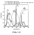
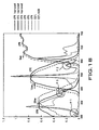
- Fig.18 shows spectral characteristics of the light sources, made up of the main white light source 21 and the auxiliary light source 22, and those of the color filter 19, matched to the spectral characteristics of the light sources.
- the spectral characteristics by a thick dotted line are those of the color filter 19Z, described above and shown in Fig.13 .
- the spectral characteristics, shown by a thick solid line are the spectral characteristics of the color filter 19 improved over the color filter 19Z for matching to the spectral characteristics of the light sources, made up of the main white light source 21 and the auxiliary light source 22.
- the red filter CFR is designed to have transmittance in a region P1 of the transmission wavelength band of the blue filter CFB equal to zero. If the transmittance of the red filter CFR in this region P1 is not zero, the blue light would be lowered in color purity.
- the red filter CFR has its peak wavelength Fpr shifted by 5 nm from 685 nm to 690 nm so that the transmission wavelength range will be shifted towards the long wavelength side as it clears the sub-peak of the main white light source 21 lying in a region P2 in the vicinity of 580 nm.
- the blue filter CFB has its peak wavelength Fpb shifted by 20 nm from 460 nm to 440 nm so that the transmission wavelength range will be shifted towards the short wavelength side as it clears the sub-peak of the main white light source 21 present in a region P3 in the vicinity of 490 nm.
- the green filter CFG has its half-value width Fhwg shifted by 10 nm from 100 nm to 90 nm so that only the transmission wavelength range on the short wavelength side will be shifted towards the long wavelength side as it clears the sub-peak of the main white light source 21 present in the region P3 in the vicinity of 490 nm.
- the display light, radiated from the color liquid crystal display panel 10 was measured with a colorimeter and chromaticity points thus found were plotted on an xy chromaticity diagram.
- a color reproducing range shown in Fig.19 was obtained.
- Figs.20 to 22 the regions of the green (G) color, blue (B) color and the red (R) color, shown in the xy- chromaticity diagram of Fig.19 , respectively, are shown to an enlarged scale. Meanwhile, in the xy chromaticity diagrams of Figs.19 to 22 , there are also shown the color reproducing range of the Adobe RGB standard, the XYZ color system prescribed by the Commission Internationale de l'Eclairage (CIE), the color reproducing range of the sRGB standard and the color reproducing range in case of using only the main white light source 21 as light source.
- CIE Commission Internationale de l'Eclairage
- the color ranges may be enlarged appreciably for the green (G) region, blue (B) region and the red (R) region in their entirety. That is, the color ranges of the green (G) region, blue (B) region and the red (R) region may further be enlarged by improving the color filter 19 so that spectral characteristics of the color filter will be matched optimally to those of the light sources made up of the main white light source 21 and the auxiliary light source 22 provided for assisting the main white light source 21.
- the degree of freedom in color creation in the display picture demonstrated on the color liquid crystal display apparatus, may be improved appreciably.
- the NTSC ratio has been improved from 74% to 93% as a result of improving the color filter 19.
- the luminance which is usually in the relationship of tradeoff with color gamut enlargement, may be improved by a factor of 1.5 as compared to the case of using only the main white light source 21. This high luminance may be achieved despite the fact that the light emission intensity of the red light emitting diode 22R, green light emitting diode 22G and the blue light emitting diode 22B, used as auxiliary light source 22, is set to approximately 20% of that of the main white light source 21.
- the color reproducing range of a picture displayed on the color liquid crystal display panel 10 may be enlarged by matching, by way of optimization, the characteristics of the red filter CFR, green filter CFG and the blue filter CFB, provided on the color liquid crystal display panel 10, to those of the main light source 21 and the auxiliary light source 22 provided on the backlight device 20.
- the emerald color of the sea, wine-red scarlet or deep green of the trees or grasses coming out may be displayed spontaneously to natural colors.
- the items of improvement for the red light emitting diode 22R, green light emitting diode 22G and the blue light emitting diode 22B, as well as the respective color filter segments of the color filter 19, need not be met in their entirety. That is, those items may be used either alone or in combinations for enlarging the color reproducing range. For example, it is sufficient that at least one of the red light emitting diode 22R, green light emitting diode 22G and the blue light emitting diode 22B is included in the auxiliary light source 22.
- the present invention is not limited to the particular configurations of the embodiment described with reference to the drawings. It will be appreciated that the present invention may encompass various changes or corrections such as may readily be arrived at by those skilled in the art within the scope of the invention as defined by the claims.
Landscapes
- Physics & Mathematics (AREA)
- Nonlinear Science (AREA)
- General Physics & Mathematics (AREA)
- Optics & Photonics (AREA)
- Crystallography & Structural Chemistry (AREA)
- Chemical & Material Sciences (AREA)
- Mathematical Physics (AREA)
- Engineering & Computer Science (AREA)
- Computer Hardware Design (AREA)
- Theoretical Computer Science (AREA)
- Liquid Crystal (AREA)
- Planar Illumination Modules (AREA)
- Optical Filters (AREA)
- Vessels And Coating Films For Discharge Lamps (AREA)
Applications Claiming Priority (2)
| Application Number | Priority Date | Filing Date | Title |
|---|---|---|---|
| JP2004306073A JP4815781B2 (ja) | 2004-10-20 | 2004-10-20 | カラー液晶表示装置及びバックライト装置 |
| PCT/JP2005/018003 WO2006043404A1 (ja) | 2004-10-20 | 2005-09-29 | カラー液晶表示装置 |
Publications (3)
| Publication Number | Publication Date |
|---|---|
| EP1804116A1 EP1804116A1 (en) | 2007-07-04 |
| EP1804116A4 EP1804116A4 (en) | 2009-02-18 |
| EP1804116B1 true EP1804116B1 (en) | 2009-08-19 |
Family
ID=36202824
Family Applications (1)
| Application Number | Title | Priority Date | Filing Date |
|---|---|---|---|
| EP05788185A Not-in-force EP1804116B1 (en) | 2004-10-20 | 2005-09-29 | Color liquid crystal display |
Country Status (8)
Cited By (4)
| Publication number | Priority date | Publication date | Assignee | Title |
|---|---|---|---|---|
| US9139767B2 (en) | 2008-12-30 | 2015-09-22 | Nanosys, Inc. | Methods for encapsulating nanocrystals and resulting compositions |
| US9199842B2 (en) | 2008-12-30 | 2015-12-01 | Nanosys, Inc. | Quantum dot films, lighting devices, and lighting methods |
| US10214686B2 (en) | 2008-12-30 | 2019-02-26 | Nanosys, Inc. | Methods for encapsulating nanocrystals and resulting compositions |
| US11198270B2 (en) | 2008-12-30 | 2021-12-14 | Nanosys, Inc. | Quantum dot films, lighting devices, and lighting methods |
Families Citing this family (25)
| Publication number | Priority date | Publication date | Assignee | Title |
|---|---|---|---|---|
| JP2005321727A (ja) * | 2004-05-11 | 2005-11-17 | Sony Corp | バックライト装置及びカラー液晶表示装置 |
| KR20070039539A (ko) * | 2004-07-15 | 2007-04-12 | 소니 가부시끼 가이샤 | 컬러필터 및 컬러 액정표시장치 |
| US7592996B2 (en) | 2006-06-02 | 2009-09-22 | Samsung Electronics Co., Ltd. | Multiprimary color display with dynamic gamut mapping |
| JP2008076899A (ja) * | 2006-09-22 | 2008-04-03 | Sony Corp | バックライト装置及び表示装置 |
| JP4666387B2 (ja) * | 2006-10-10 | 2011-04-06 | シャープ株式会社 | バックライトユニット及び該ユニットを備える画像表示装置 |
| JP5157140B2 (ja) | 2006-11-29 | 2013-03-06 | ソニー株式会社 | 記録装置、記録方法、情報処理装置、情報処理方法、撮像装置およびビデオシステム |
| JP4285532B2 (ja) * | 2006-12-01 | 2009-06-24 | ソニー株式会社 | バックライト制御装置、バックライト制御方法、および液晶表示装置 |
| TWI347467B (en) | 2006-12-15 | 2011-08-21 | Au Optronics Corp | Liquid crystal display |
| JP4264560B2 (ja) * | 2007-01-24 | 2009-05-20 | ソニー株式会社 | バックライト装置、バックライト制御方法、および液晶表示装置 |
| JP2008270145A (ja) * | 2007-03-22 | 2008-11-06 | Mitsubishi Electric Corp | 液晶表示装置およびバックライト装置 |
| WO2008114535A1 (ja) * | 2007-03-22 | 2008-09-25 | Mitsubishi Electric Corporation | 液晶表示装置およびバックライト装置 |
| TWI398700B (zh) * | 2009-12-30 | 2013-06-11 | Au Optronics Corp | 使用量子點螢光粉之顯示裝置及其製造方法 |
| WO2011114374A1 (ja) * | 2010-03-17 | 2011-09-22 | Necディスプレイソリューションズ株式会社 | バックライト装置、バックライト装置の駆動方法 |
| CN101868086B (zh) * | 2010-05-17 | 2014-03-05 | 王孟源 | 一种led光源模组及提高led光源模组显色指数的方法 |
| KR20120020226A (ko) * | 2010-08-27 | 2012-03-08 | 삼성전자주식회사 | 디스플레이장치 및 그 전원회로장치 |
| CN102878467B (zh) * | 2012-10-19 | 2015-02-11 | 纳晶科技股份有限公司 | 低色温照明组件 |
| KR20140089879A (ko) | 2013-01-08 | 2014-07-16 | 삼성디스플레이 주식회사 | 액정 표시 장치 |
| US10268078B2 (en) * | 2013-08-23 | 2019-04-23 | Sharp Kabushiki Kaisha | Liquid crystal display |
| US9410664B2 (en) | 2013-08-29 | 2016-08-09 | Soraa, Inc. | Circadian friendly LED light source |
| CN105261326A (zh) * | 2015-10-09 | 2016-01-20 | 惠州Tcl移动通信有限公司 | 调整显示色域的显示设备及其调整显示色域的方法 |
| EP3401894B1 (en) * | 2016-01-08 | 2023-11-01 | Dainippon Printing Co., Ltd. | Image display device |
| CN105892145B (zh) * | 2016-04-05 | 2020-07-03 | 武汉华星光电技术有限公司 | 一种显示器及其显示模组 |
| KR102040293B1 (ko) * | 2016-08-29 | 2019-11-04 | 삼성에스디아이 주식회사 | 액정표시장치 |
| KR20200057256A (ko) | 2018-11-16 | 2020-05-26 | 삼성전자주식회사 | 디스플레이 장치 및 그 구동 방법 |
| CN114721184B (zh) * | 2021-11-25 | 2023-06-20 | 友达光电股份有限公司 | 显示装置 |
Family Cites Families (46)
| Publication number | Priority date | Publication date | Assignee | Title |
|---|---|---|---|---|
| US4870484A (en) * | 1983-05-13 | 1989-09-26 | Seiko Epson Corporation | Color display device using light shutter and color filters |
| US5143433A (en) * | 1991-11-01 | 1992-09-01 | Litton Systems Canada Limited | Night vision backlighting system for liquid crystal displays |
| JPH06227284A (ja) * | 1993-02-09 | 1994-08-16 | Asahi Glass Co Ltd | ヘッドアップディスプレイ |
| JP3292809B2 (ja) * | 1996-09-25 | 2002-06-17 | 松下電器産業株式会社 | カラー液晶表示素子 |
| US6633301B1 (en) * | 1999-05-17 | 2003-10-14 | Displaytech, Inc. | RGB illuminator with calibration via single detector servo |
| JP2001135118A (ja) * | 1999-11-02 | 2001-05-18 | Toshiba Corp | 面光源装置及びそれを用いた平面表示装置 |
| US6666567B1 (en) * | 1999-12-28 | 2003-12-23 | Honeywell International Inc. | Methods and apparatus for a light source with a raised LED structure |
| TWI240241B (en) * | 2000-05-04 | 2005-09-21 | Koninkl Philips Electronics Nv | Assembly of a display device and an illumination system |
| TW528169U (en) * | 2000-05-04 | 2003-04-11 | Koninkl Philips Electronics Nv | Assembly of a display device and an illumination system |
| US6608614B1 (en) * | 2000-06-22 | 2003-08-19 | Rockwell Collins, Inc. | Led-based LCD backlight with extended color space |
| JP3847532B2 (ja) * | 2000-07-05 | 2006-11-22 | 株式会社日立製作所 | 液晶モジュールおよびこの液晶モジュールを搭載した液晶モニター |
| JP3822037B2 (ja) * | 2000-08-04 | 2006-09-13 | 株式会社日立製作所 | 液晶表示装置 |
| KR100367011B1 (ko) * | 2000-08-21 | 2003-01-09 | 엘지.필립스 엘시디 주식회사 | 액정표시장치 |
| JP3523170B2 (ja) * | 2000-09-21 | 2004-04-26 | 株式会社東芝 | 表示装置 |
| JP3538149B2 (ja) * | 2001-01-30 | 2004-06-14 | Nec液晶テクノロジー株式会社 | 反射型液晶表示装置及びその製造方法 |
| JP3940596B2 (ja) * | 2001-05-24 | 2007-07-04 | 松下電器産業株式会社 | 照明光源 |
| JP4899261B2 (ja) * | 2001-07-05 | 2012-03-21 | 大日本印刷株式会社 | カラー液晶ディスプレイ |
| DE10137042A1 (de) * | 2001-07-31 | 2003-02-20 | Patent Treuhand Ges Fuer Elektrische Gluehlampen Mbh | Planare Lichtquelle auf LED-Basis |
| JP3840940B2 (ja) * | 2001-09-28 | 2006-11-01 | 株式会社日立製作所 | 画像表示装置 |
| JP3924473B2 (ja) * | 2002-02-08 | 2007-06-06 | シャープ株式会社 | 発光装置及び該発光装置を用いた表示装置 |
| JP4212332B2 (ja) * | 2002-03-05 | 2009-01-21 | シャープ株式会社 | 表示装置 |
| KR100878206B1 (ko) * | 2002-08-13 | 2009-01-13 | 삼성전자주식회사 | 광학 시트, 이를 이용한 백라이트 어셈블리 및 액정표시장치 |
| JP2004163902A (ja) * | 2002-08-30 | 2004-06-10 | Mitsubishi Chemicals Corp | カラー液晶表示装置及び感光性着色樹脂組成物 |
| JP4611604B2 (ja) * | 2002-09-30 | 2011-01-12 | 独立行政法人情報通信研究機構 | 画像表示装置 |
| KR100698046B1 (ko) * | 2002-12-24 | 2007-03-23 | 엘지.필립스 엘시디 주식회사 | 백라이트 유닛 어셈블리 |
| DE602004005768T2 (de) * | 2003-03-28 | 2008-05-15 | Philips Lumileds Lighting Company LLC, (n. d. Ges. d. Staates Delaware), San Jose | Rücklicht-Beleuchtungssystem und Anzeigevorrichtung |
| TWI282022B (en) * | 2003-03-31 | 2007-06-01 | Sharp Kk | Surface lighting device and liquid crystal display device using the same |
| KR20050091701A (ko) * | 2003-04-01 | 2005-09-15 | 가부시키가이샤 휴네트 | Led 구동장치 및 led 구동방법 |
| JP2004309509A (ja) * | 2003-04-01 | 2004-11-04 | Hunet Inc | 表示装置の調整方法 |
| JP4417784B2 (ja) * | 2003-09-05 | 2010-02-17 | シャープ株式会社 | 発光装置及び表示装置 |
| US20050057484A1 (en) * | 2003-09-15 | 2005-03-17 | Diefenbaugh Paul S. | Automatic image luminance control with backlight adjustment |
| US7052152B2 (en) * | 2003-10-03 | 2006-05-30 | Philips Lumileds Lighting Company, Llc | LCD backlight using two-dimensional array LEDs |
| JP4202229B2 (ja) * | 2003-10-15 | 2008-12-24 | 株式会社 日立ディスプレイズ | 液晶表示装置 |
| JP4628770B2 (ja) * | 2004-02-09 | 2011-02-09 | 株式会社日立製作所 | 照明装置を備えた画像表示装置及び画像表示方法 |
| JP2005234134A (ja) * | 2004-02-18 | 2005-09-02 | Sony Corp | 液晶表示用バックライト光源装置及びカラー液晶表示装置 |
| KR101111459B1 (ko) * | 2004-03-31 | 2012-03-13 | 도판 인사츠 가부시키가이샤 | 컬러필터 및 이것을 구비한 액정표시장치 |
| JP2005321727A (ja) * | 2004-05-11 | 2005-11-17 | Sony Corp | バックライト装置及びカラー液晶表示装置 |
| KR101015299B1 (ko) * | 2004-06-29 | 2011-02-15 | 엘지디스플레이 주식회사 | 화질이 향상된 액정표시소자 |
| US7502010B2 (en) * | 2004-08-31 | 2009-03-10 | Nvidia Corporation | Variable brightness LCD backlight |
| US7324080B1 (en) * | 2004-12-03 | 2008-01-29 | Sysview Technology, Inc. | Backlighting in liquid crystal flat panel display |
| JP3883134B2 (ja) * | 2005-01-25 | 2007-02-21 | 日東電工株式会社 | 液晶表示装置 |
| JP4600098B2 (ja) * | 2005-03-14 | 2010-12-15 | ソニー株式会社 | カラー液晶表示装置 |
| JP4175426B2 (ja) * | 2006-05-30 | 2008-11-05 | ソニー株式会社 | バックライト装置及びカラー画像表示装置 |
| US7696964B2 (en) * | 2006-06-09 | 2010-04-13 | Philips Lumileds Lighting Company, Llc | LED backlight for LCD with color uniformity recalibration over lifetime |
| US8018424B2 (en) * | 2006-10-19 | 2011-09-13 | Au Optronics Corporation | Backlight device with zone control |
| JP4987456B2 (ja) * | 2006-12-25 | 2012-07-25 | 三菱電機株式会社 | レーダ装置 |
-
2004
- 2004-10-20 JP JP2004306073A patent/JP4815781B2/ja not_active Expired - Fee Related
-
2005
- 2005-09-29 CN CN2005800352279A patent/CN101040214B/zh not_active Expired - Fee Related
- 2005-09-29 US US11/665,878 patent/US20080100551A1/en not_active Abandoned
- 2005-09-29 EP EP05788185A patent/EP1804116B1/en not_active Not-in-force
- 2005-09-29 KR KR1020077008966A patent/KR20070068390A/ko not_active Ceased
- 2005-09-29 WO PCT/JP2005/018003 patent/WO2006043404A1/ja active Application Filing
- 2005-09-29 DE DE602005016133T patent/DE602005016133D1/de active Active
- 2005-10-03 TW TW094134493A patent/TWI287674B/zh not_active IP Right Cessation
Cited By (11)
| Publication number | Priority date | Publication date | Assignee | Title |
|---|---|---|---|---|
| US9139767B2 (en) | 2008-12-30 | 2015-09-22 | Nanosys, Inc. | Methods for encapsulating nanocrystals and resulting compositions |
| US9199842B2 (en) | 2008-12-30 | 2015-12-01 | Nanosys, Inc. | Quantum dot films, lighting devices, and lighting methods |
| US9804319B2 (en) | 2008-12-30 | 2017-10-31 | Nanosys, Inc. | Quantum dot films, lighting devices, and lighting methods |
| US10214686B2 (en) | 2008-12-30 | 2019-02-26 | Nanosys, Inc. | Methods for encapsulating nanocrystals and resulting compositions |
| US10302845B2 (en) | 2008-12-30 | 2019-05-28 | Nanosys, Inc. | Quantum dot films, lighting devices, and lighting methods |
| US10444423B2 (en) | 2008-12-30 | 2019-10-15 | Nanosys, Inc. | Quantum dot films, lighting devices, and lighting methods |
| US10544362B2 (en) | 2008-12-30 | 2020-01-28 | Nanosys, Inc. | Methods for encapsulating nanocrystals and resulting compositions |
| US10899105B2 (en) | 2008-12-30 | 2021-01-26 | Nanosys, Inc. | Quantum dot films, lighting devices, and lighting methods |
| US11198270B2 (en) | 2008-12-30 | 2021-12-14 | Nanosys, Inc. | Quantum dot films, lighting devices, and lighting methods |
| US11396158B2 (en) | 2008-12-30 | 2022-07-26 | Nanosys, Inc. | Quantum dot films, lighting devices, and lighting methods |
| US11420412B2 (en) | 2008-12-30 | 2022-08-23 | Nanosys, Inc. | Quantum dot films, lighting devices, and lighting methods |
Also Published As
| Publication number | Publication date |
|---|---|
| KR20070068390A (ko) | 2007-06-29 |
| CN101040214A (zh) | 2007-09-19 |
| CN101040214B (zh) | 2012-04-25 |
| DE602005016133D1 (de) | 2009-10-01 |
| EP1804116A4 (en) | 2009-02-18 |
| JP4815781B2 (ja) | 2011-11-16 |
| TWI287674B (en) | 2007-10-01 |
| EP1804116A1 (en) | 2007-07-04 |
| WO2006043404A1 (ja) | 2006-04-27 |
| US20080100551A1 (en) | 2008-05-01 |
| JP2006119295A (ja) | 2006-05-11 |
| TW200615664A (en) | 2006-05-16 |
Similar Documents
| Publication | Publication Date | Title |
|---|---|---|
| EP1804116B1 (en) | Color liquid crystal display | |
| EP1813978B1 (en) | Color liquid crystal display | |
| US7474366B2 (en) | Color liquid crystal display device | |
| US7663714B2 (en) | Backlight device and color liquid crystal display apparatus | |
| US7808585B2 (en) | Color filter and color LCD apparatus having red filter with a peak wavelength between 685 nm and 690 nm and a red light source having a peak wavelength of between 640 nm and 645 nm | |
| US7789527B2 (en) | Backlight device and color liquid crystal display | |
| US20060170319A1 (en) | Backlight device and liquid crystal display device | |
| JP2005234133A (ja) | カラー液晶表示用カラーフィルタ及びカラー液晶表示装置 | |
| JP4631485B2 (ja) | カラー液晶表示装置 | |
| JP4779308B2 (ja) | カラー液晶表示装置 |
Legal Events
| Date | Code | Title | Description |
|---|---|---|---|
| PUAI | Public reference made under article 153(3) epc to a published international application that has entered the european phase |
Free format text: ORIGINAL CODE: 0009012 |
|
| 17P | Request for examination filed |
Effective date: 20070323 |
|
| AK | Designated contracting states |
Kind code of ref document: A1 Designated state(s): DE FR GB NL |
|
| DAX | Request for extension of the european patent (deleted) | ||
| RBV | Designated contracting states (corrected) |
Designated state(s): DE FR GB NL |
|
| A4 | Supplementary search report drawn up and despatched |
Effective date: 20090115 |
|
| RIC1 | Information provided on ipc code assigned before grant |
Ipc: G02F 1/1335 20060101ALI20090109BHEP Ipc: G02F 1/13357 20060101AFI20061003BHEP Ipc: G02B 5/20 20060101ALN20090109BHEP Ipc: F21S 2/00 20060101ALN20090109BHEP |
|
| GRAP | Despatch of communication of intention to grant a patent |
Free format text: ORIGINAL CODE: EPIDOSNIGR1 |
|
| GRAS | Grant fee paid |
Free format text: ORIGINAL CODE: EPIDOSNIGR3 |
|
| GRAA | (expected) grant |
Free format text: ORIGINAL CODE: 0009210 |
|
| AK | Designated contracting states |
Kind code of ref document: B1 Designated state(s): DE FR GB NL |
|
| REG | Reference to a national code |
Ref country code: GB Ref legal event code: FG4D |
|
| REF | Corresponds to: |
Ref document number: 602005016133 Country of ref document: DE Date of ref document: 20091001 Kind code of ref document: P |
|
| NLV1 | Nl: lapsed or annulled due to failure to fulfill the requirements of art. 29p and 29m of the patents act | ||
| PG25 | Lapsed in a contracting state [announced via postgrant information from national office to epo] |
Ref country code: NL Free format text: LAPSE BECAUSE OF FAILURE TO SUBMIT A TRANSLATION OF THE DESCRIPTION OR TO PAY THE FEE WITHIN THE PRESCRIBED TIME-LIMIT Effective date: 20090819 |
|
| PLBE | No opposition filed within time limit |
Free format text: ORIGINAL CODE: 0009261 |
|
| STAA | Information on the status of an ep patent application or granted ep patent |
Free format text: STATUS: NO OPPOSITION FILED WITHIN TIME LIMIT |
|
| 26N | No opposition filed |
Effective date: 20100520 |
|
| PGFP | Annual fee paid to national office [announced via postgrant information from national office to epo] |
Ref country code: DE Payment date: 20110923 Year of fee payment: 7 Ref country code: FR Payment date: 20110928 Year of fee payment: 7 Ref country code: GB Payment date: 20110920 Year of fee payment: 7 |
|
| GBPC | Gb: european patent ceased through non-payment of renewal fee |
Effective date: 20120929 |
|
| REG | Reference to a national code |
Ref country code: FR Ref legal event code: ST Effective date: 20130531 |
|
| PG25 | Lapsed in a contracting state [announced via postgrant information from national office to epo] |
Ref country code: GB Free format text: LAPSE BECAUSE OF NON-PAYMENT OF DUE FEES Effective date: 20120929 Ref country code: DE Free format text: LAPSE BECAUSE OF NON-PAYMENT OF DUE FEES Effective date: 20130403 |
|
| REG | Reference to a national code |
Ref country code: DE Ref legal event code: R119 Ref document number: 602005016133 Country of ref document: DE Effective date: 20130403 |
|
| PG25 | Lapsed in a contracting state [announced via postgrant information from national office to epo] |
Ref country code: FR Free format text: LAPSE BECAUSE OF NON-PAYMENT OF DUE FEES Effective date: 20121001 |