EP1803890A2 - Speziell geformte Leiterverpackungen und Transport damit - Google Patents
Speziell geformte Leiterverpackungen und Transport damit Download PDFInfo
- Publication number
- EP1803890A2 EP1803890A2 EP06126600A EP06126600A EP1803890A2 EP 1803890 A2 EP1803890 A2 EP 1803890A2 EP 06126600 A EP06126600 A EP 06126600A EP 06126600 A EP06126600 A EP 06126600A EP 1803890 A2 EP1803890 A2 EP 1803890A2
- Authority
- EP
- European Patent Office
- Prior art keywords
- ladders
- carriage
- bar
- wheels
- rollers
- Prior art date
- Legal status (The legal status is an assumption and is not a legal conclusion. Google has not performed a legal analysis and makes no representation as to the accuracy of the status listed.)
- Withdrawn
Links
- 230000003068 static effect Effects 0.000 description 2
- 238000000605 extraction Methods 0.000 description 1
Images



Classifications
-
- E—FIXED CONSTRUCTIONS
- E06—DOORS, WINDOWS, SHUTTERS, OR ROLLER BLINDS IN GENERAL; LADDERS
- E06C—LADDERS
- E06C5/00—Ladders characterised by being mounted on undercarriages or vehicles Securing ladders on vehicles
- E06C5/02—Ladders characterised by being mounted on undercarriages or vehicles Securing ladders on vehicles with rigid longitudinal members
- E06C5/04—Ladders characterised by being mounted on undercarriages or vehicles Securing ladders on vehicles with rigid longitudinal members capable of being elevated or extended ; Fastening means during transport, e.g. mechanical, hydraulic
-
- B—PERFORMING OPERATIONS; TRANSPORTING
- B66—HOISTING; LIFTING; HAULING
- B66B—ELEVATORS; ESCALATORS OR MOVING WALKWAYS
- B66B9/00—Kinds or types of lifts in, or associated with, buildings or other structures
- B66B9/16—Mobile or transportable lifts specially adapted to be shifted from one part of a building or other structure to another part or to another building or structure
- B66B9/193—Mobile or transportable lifts specially adapted to be shifted from one part of a building or other structure to another part or to another building or structure with inclined liftways
Definitions
- the present industrial invention refers to a package of ladders and a carriage thereof. This equipment is mounted on motor-vehicles and permits to reach considerable heights.
- Said particular equipment includes ladders and carriage.
- This equipment is mounted on a motor-vehicle and is used to position things and/or persons at a wished height, in particular a considerable height, outside buildings, for instance for removals to building flats or in case of emergency interventions in buildings of considerable heights.
- said operations are effected through particular carriages which are moved along ladders which are disposed on a motor-vehicle.
- said ladders form structures which are extended by means of a telescopic mechanism. Their extension possibility depends on the number of sections of the ladder structure and the length of the ladder structure can be considerable.
- the type of said structures is very important as well as the type of carriage running along the ladder structure.
- the ladder sections which are available on the market comprise two profiles which are connected to each other, only in the lower part, through rigid connections. This feature permits to produce ladders of a satisfying but not excellent lateral rigidity and therefore, the so-obtained structures have only a certain degree of flexibility, which is prejudicial to the safety.
- the shape (in general a C-shape), of the profiles, which are utilized to produce the ladder sections, is not an optimal shape for the ladder sections because the run of the carriage wheels engages only the upper wings of the C-shaped profiles.
- the upper wings of the C-shape profiles tend, under load, to locally deform and the two C-shapes tend to open wide apart since only the lower parts of the two C-shapes are connected to each other through said rigid connections, which involves a real risk for the carriage wheels to go out of the wings of the C-shapes.
- the aim of the present invention is to remove all the above cited drawbacks and further ones by proposing a system inclusive of ladders and carriage offering a high standard of safety without increasing the weight but increasing the stability of the single profiles as well as the stability of the single ladder sections on the planes of working.
- a ladders-carriage system characterized by the fact of comprising ladders showing a closed, substantially squared profile and at least a translating carriage provided with running wheels positioned at the outer edges of said ladders.
- the structure of the present invention is new and is very advantageous because it is very light thanks to the type of profile utilized and it is very static, as well.
- the new structure is very advantageous because it is very static.
- the ladder sections are shaped like a closed polygon and achieve a high degree of rigidity and consequently, a high standard of safety.
- a lateral running of the carriage (laterally to the profiles) provides a higher stability to the movement of the carriage.
- Another feature of the present structure is the position of the windlass that moves the carriage: the windlass is positioned at the top of the ladder, which does reduce the load in comparison with the solutions of the known
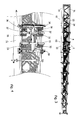
- number 1 denotes a structure according to the present invention.
- the structure 1 comprises a carriage 2 and a package of ladders 3.
- the package of ladders 3 includes at least two ladder sections. In the present embodiment, there are seven ladder sections.
- Each ladder section comprises two lateral profiles which are connected to each other through a slanting or perpendicular cross-bar which is slanting or perpendicular to the profiles.
- the carriage 2 is disposed on a first ladder section 61 of the ladders package 3.
- the ladder section 61 comprises two lateral profiles 21 which are connected to each other through both slanting cross-bars 24 and perpendicular cross-bars 25, which are slanting and perpendicular to the profiles 21, respectively.
- the ladder sections are shaped in such a way as to be inserted in one another on forming a telescopic structure.
- each lateral profile is shaped in such a way as to permit the carriage 2 to slide.
- the upper part of the profile 21 has a projection or rail 4 which develops according to the direction of the ladders package 3 , as it can be seen in Figures 1 and 13.
- the rail 4 divides the upper part of the profile 21 in two surfaces 5, 6.
- the wheels of the carriage 2 run on the two surfaces 5, 6.
- the surface 6 is connected with the vertical surface of the profile 21 through a rectangular profile element having a lateral surface 17 as well as a lower surface 18, as it can be seen in Figure 13.
- the ladder sectors inside the first ladder section 61 have the same conformation.
- the second ladder section 62 also has a rail 14 and two surfaces 15, 16 on the upper part of the profile 22, as represented in Fig. 1.
- each ladder section comprises a connecting element 72 which is provided with a rail 8 which is connected with the rail 4 of the profile on which the connecting element 72 is mounted.
- the height of said rail 8 reduces in the direction of the opposite end to said connection.
- the connecting element 72 has a surface 10 which is adjacent to the rail 8.
- the surface 10 is shaped like a right-angled triangle which has a side connected with the surface 6 of the ladder section.
- each ladder section comprises a slip element 71 which is placed laterally to the ladder section itself near the connecting element 72.
- Said slip element 71 comprises both a support 73 and a curved element 74 which is connected with said support 73.
- the curved element 74 is to maintain the wheels of the carriage 2 adjacent to the lateral surfaces of the profiles 21, 22, 23 of the ladder sections.
- a loading platform is placed on the carriage 2 for the operator or things to be lifted or lowered.
- the carriage 2 is provided with wheels and rolls which are positioned adjacently to the surfaces 5, 6, 15, 16 and rails 4, 14 in such a way as not to wriggle out and to translate at the same time, independently of the width of the ladder section.
- the carriage 2 is provided with a supporting cross-bar 31 on which a first element 50, a first bar 32, a second bar 34 and a second element 40 are mounted in succession.
- the first element 50 has a variable width and is provided with steering-wheels.
- the first bar 30 is provided with a pair of roller-guide units 33.
- the second bar 34 is provided with two pairs of roller-guide units 35, 37.
- the second element 40 has a variable width.
- the first element 50 provided with the steering-wheels comprises a bar 51 which is connected with the supporting cross-bar 51 transversely.
- Each end of said bar 51 has a cavity in which a tubular element 52 moves.
- An end of the tubular element 52 is provided with a support 53 which is orthogonal to the tubular element 52.
- the supports 53 are disposed symmetrically to the supporting cross-bar 31 and their movement is symmetrical thanks to a lever system.
- the lever system comprises a central bar 59 which rotates around an apex 60 which is connected with the supporting cross-bar 31 and bars 58 which are connected with their respective support 53 and end part of the central bar 59.
- each spring element 57 is connected with the support 53 while the other end is connected with the bar 51.
- the first bar 32 is provided with two units of rollers 33 which are arranged symmetrically to the supporting cross-bar 31.
- each roller unit is provided with eight rollers which have the same axis of rotation and are spaced from each other. The distance between two rollers corresponds to the width of the rail 4, 14.
- the second bar 34 is provided with four units of rollers 35, 36, these roller units being disposed symmetrically.
- two roller units 35 are disposed symmetrically in front of the bar 34 while the remaining roller units 36 are disposed symmetrically behind the bar 34.
- the second bar 34 is provided with a comb element 37 which is placed between the bar 34 and the roller units 36.
- the second element 40 having a variable length comprises a support 41 which comprises cavities in which two tubular elements 42 translate.
- the ends of each tubular element 42 are provided with supports 44 on which the wheels 45 are mounted.
- the second element 40 of a variable width is provided with a lever system which comprises a central bar 47 and two lateral bars 46 which press, together with the springs 43, the wheels 45 against the profile on which the carriage is mounted.
- the sliding system comprises seven ladder sections.
- Each ladder section comprises a rail, two lateral surfaces which are disposed laterally to the rail, and a lateral surface which is perpendicular to said surfaces.
- the sliding system comprises seven parallel rails 4, 14, which are arranged on different planes, surfaces 5, 6, 15, 16, which are adjacent to said rails, and lateral surfaces 21, 22.
- the sliding of the carriage is made stable and safe thanks to the sliding of the wheels and rollers on the ladders package on allowing the carriage 2 to move only parallelly to the direction of development of the ladders package 3.
- the rails 4, 14 are placed between the rollers of the roller units 33, 35, 36.
- the wheels 45 are positioned in such a way as to roll on the lateral surfaces 21 of the profiles and, at the same time, to press against the same surfaces.
- the ends of the steering-wheel element 50 are provided with upper wheels 55 which beat and slide on the surface 5, 15 which is more internal than the rail 4, 14.
- the rollers 63 are arranged on the bar 54 which is connected with the support 53 and therefore, the rollers 63 beat on the upper part of the profile 21. In particular, the rollers 63 beat on the higher external surface 17. Besides, the rollers 63 are kept under pressure by means of a spring system 57.
- the steering-wheel element 50 is not able to shift in respect of the ladder section on which said element is disposed.
- the only movement the element 50 accomplishes is a movement of translation.
- the direction of this movement is parallel to the direction of extension of the ladders package.
- the conformation of the carriage 2 permits the carriage to slide even in the passage from a ladder section to the following ladder section.
- the position of the chute element 71 and the position of the connecting elements 72 permits both the steering-wheel element 50 and the element 40 of variable width to press against the lateral surfaces.
- the curved element 74 and the connecting element 72 guide the rollers 63 according to the width of the ladder section by means of a spring system 57.
- the wheels 55 continue running from the surface 5 of the first ladder section to the surface 15 of the following ladder section, similarly to the lower wheels 56.
- variable width element 40 The width of the variable width element 40 is reduced on maintaining the wheels 45 against the surface 17.
- the rail 4 of a ladder section frees the seat between two rollers of the units 33, 35, 36 and the rail 14 of the following ladder section engages in a seat between two rollers, this seat being adjacent to said seat.
- the system is equipped with suitable ratchet gears 37 which act in case of a breakage of the rope moving the carriage.
- the windlass of movement of the carriage is placed on the top (last ladder section) of the ladders package to avoid a doubling of the load, should the windlass be placed on the bottom.
- the extracting system for the extraction of the ladder sections of the ladders package consists of a windlass with four draughts of rope for the first ladder section and a windlass with double chains for the following ladder sections.
- a technician of the sector can conceive some versions or changes that are to be considered as included in the scope of protection of the present invention.
Landscapes
- Engineering & Computer Science (AREA)
- Structural Engineering (AREA)
- Civil Engineering (AREA)
- Transportation (AREA)
- Automation & Control Theory (AREA)
- Mechanical Engineering (AREA)
- Handcart (AREA)
- Ladders (AREA)
Applications Claiming Priority (1)
| Application Number | Priority Date | Filing Date | Title |
|---|---|---|---|
| ITVR20050159 ITVR20050159A1 (it) | 2005-12-28 | 2005-12-28 | Pacco scale particolarmente conformato e carrello ad esso accoppiato |
Publications (2)
| Publication Number | Publication Date |
|---|---|
| EP1803890A2 true EP1803890A2 (de) | 2007-07-04 |
| EP1803890A3 EP1803890A3 (de) | 2008-06-25 |
Family
ID=37891760
Family Applications (1)
| Application Number | Title | Priority Date | Filing Date |
|---|---|---|---|
| EP06126600A Withdrawn EP1803890A3 (de) | 2005-12-28 | 2006-12-20 | Speziell geformte Leiterverpackungen und Transport damit |
Country Status (4)
| Country | Link |
|---|---|
| EP (1) | EP1803890A3 (de) |
| DE (1) | DE06126600T1 (de) |
| ES (1) | ES2288456T1 (de) |
| IT (1) | ITVR20050159A1 (de) |
Cited By (2)
| Publication number | Priority date | Publication date | Assignee | Title |
|---|---|---|---|---|
| IT202200000818A1 (it) * | 2022-01-19 | 2023-07-19 | Stp S R L | Apparato elevatore perfezionato |
| CN118130037A (zh) * | 2024-01-03 | 2024-06-04 | 北京航空航天大学 | 一种气动噪声风洞试验用起落架缩比模型装置及mems麦克风阵列试验方法 |
Citations (2)
| Publication number | Priority date | Publication date | Assignee | Title |
|---|---|---|---|---|
| GB624668A (en) | 1947-02-04 | 1949-06-14 | Joseph Folkard Eden | Improvements relating to hoists |
| EP0317782A1 (de) | 1987-11-23 | 1989-05-31 | Albert Böcker GmbH & Co. KG | Schrägaufzug, insbesondere Material- und/oder Pesonenaufzug |
Family Cites Families (2)
| Publication number | Priority date | Publication date | Assignee | Title |
|---|---|---|---|---|
| JPS6092127A (ja) * | 1983-10-27 | 1985-05-23 | Tokyu Car Corp | 物揚作業車 |
| DE3625296A1 (de) * | 1986-04-26 | 1987-10-29 | Iveco Magirus | Leiteranordnung mit ausschiebbaren leiterteilen |
-
2005
- 2005-12-28 IT ITVR20050159 patent/ITVR20050159A1/it unknown
-
2006
- 2006-12-20 EP EP06126600A patent/EP1803890A3/de not_active Withdrawn
- 2006-12-20 ES ES06126600T patent/ES2288456T1/es active Pending
- 2006-12-20 DE DE2006126600 patent/DE06126600T1/de active Pending
Patent Citations (2)
| Publication number | Priority date | Publication date | Assignee | Title |
|---|---|---|---|---|
| GB624668A (en) | 1947-02-04 | 1949-06-14 | Joseph Folkard Eden | Improvements relating to hoists |
| EP0317782A1 (de) | 1987-11-23 | 1989-05-31 | Albert Böcker GmbH & Co. KG | Schrägaufzug, insbesondere Material- und/oder Pesonenaufzug |
Cited By (2)
| Publication number | Priority date | Publication date | Assignee | Title |
|---|---|---|---|---|
| IT202200000818A1 (it) * | 2022-01-19 | 2023-07-19 | Stp S R L | Apparato elevatore perfezionato |
| CN118130037A (zh) * | 2024-01-03 | 2024-06-04 | 北京航空航天大学 | 一种气动噪声风洞试验用起落架缩比模型装置及mems麦克风阵列试验方法 |
Also Published As
| Publication number | Publication date |
|---|---|
| ITVR20050159A1 (it) | 2007-06-29 |
| DE06126600T1 (de) | 2008-01-31 |
| EP1803890A3 (de) | 2008-06-25 |
| ES2288456T1 (es) | 2008-01-16 |
Similar Documents
| Publication | Publication Date | Title |
|---|---|---|
| CN111058618B (zh) | 可组合式伸缩套筒顶升装置及其方法 | |
| EP2858935B1 (de) | Verfahren und montagesystem zur montage von aufzugskomponenten | |
| DE10318675B4 (de) | Hebebühne | |
| US20090321189A1 (en) | Lifting device, particularly for motor vehicles | |
| EP3455155B1 (de) | Fahrschienenhebebühne für fahrzeuge sowie hubeinrichtung für fahrschienenhebebühne | |
| EP1184332B1 (de) | Fahrzeug-Hebebühne | |
| KR101878661B1 (ko) | 주차설비용 차량운반장치 | |
| CN102979449A (zh) | 云梯机构和高空作业机械 | |
| CN105060196A (zh) | 具有易操作式平台结构的高空作业平台 | |
| WO2014199301A1 (en) | Multi-wire frame for cutting blocks of stone material into slabs | |
| KR20150103689A (ko) | 사다리 세트, 특히 소방용 사다리 및 사다리 세트가 장착된 차량 | |
| CN105000512A (zh) | 一种具有易进入式栏杆门的剪叉式高空作业平台 | |
| KR101288370B1 (ko) | 터널용 작업대차 | |
| EP3412580B1 (de) | Vorrichtung zur veränderung der höhe einer passagiertreppe | |
| PL169041B1 (pl) | Uklad podnosnikowy, zwlaszcza dla pojazdów mechanicznych PL | |
| CN117188313B (zh) | 一种可平稳移动的悬挂施工装置 | |
| CA2524128A1 (en) | Scaffolding structure | |
| CN105016261A (zh) | 具有易操作式活动平台锁的剪叉式高空作业平台 | |
| KR101878662B1 (ko) | 주차설비용 차량운반장치 | |
| HUT71437A (en) | Chain guided parking system | |
| AT520889B1 (de) | Heber mit mindestens einer vertikal verfahrbaren Hubplattform mit einem Riemenantrieb | |
| WO2017153724A1 (en) | Elevating platform | |
| EP1118716B1 (de) | Vorrichtung zur Wartung von Brücken | |
| ES3052873T3 (en) | Vertical handling platform for motor vehicles | |
| KR102556239B1 (ko) | 터널 선로용 고소 작업 대차 조립공법 |
Legal Events
| Date | Code | Title | Description |
|---|---|---|---|
| PUAI | Public reference made under article 153(3) epc to a published international application that has entered the european phase |
Free format text: ORIGINAL CODE: 0009012 |
|
| AK | Designated contracting states |
Kind code of ref document: A2 Designated state(s): AT BE BG CH CY CZ DE DK EE ES FI FR GB GR HU IE IS IT LI LT LU LV MC NL PL PT RO SE SI SK TR |
|
| AX | Request for extension of the european patent |
Extension state: AL BA HR MK YU |
|
| EL | Fr: translation of claims filed | ||
| TCNL | Nl: translation of patent claims filed | ||
| DET | De: translation of patent claims | ||
| PUAL | Search report despatched |
Free format text: ORIGINAL CODE: 0009013 |
|
| AK | Designated contracting states |
Kind code of ref document: A3 Designated state(s): AT BE BG CH CY CZ DE DK EE ES FI FR GB GR HU IE IS IT LI LT LU LV MC NL PL PT RO SE SI SK TR |
|
| AX | Request for extension of the european patent |
Extension state: AL BA HR MK RS |
|
| 17P | Request for examination filed |
Effective date: 20081218 |
|
| AKX | Designation fees paid |
Designated state(s): AT BE BG CH CY CZ DE DK EE ES FI FR GB GR HU IE IS IT LI LT LU LV MC NL PL PT RO SE SI SK TR |
|
| 17Q | First examination report despatched |
Effective date: 20090325 |
|
| GRAP | Despatch of communication of intention to grant a patent |
Free format text: ORIGINAL CODE: EPIDOSNIGR1 |
|
| STAA | Information on the status of an ep patent application or granted ep patent |
Free format text: STATUS: THE APPLICATION IS DEEMED TO BE WITHDRAWN |
|
| 18D | Application deemed to be withdrawn |
Effective date: 20110607 |