EP1801911A1 - Antenne für ein Kraftfahrzeug - Google Patents
Antenne für ein Kraftfahrzeug Download PDFInfo
- Publication number
- EP1801911A1 EP1801911A1 EP06024980A EP06024980A EP1801911A1 EP 1801911 A1 EP1801911 A1 EP 1801911A1 EP 06024980 A EP06024980 A EP 06024980A EP 06024980 A EP06024980 A EP 06024980A EP 1801911 A1 EP1801911 A1 EP 1801911A1
- Authority
- EP
- European Patent Office
- Prior art keywords
- antenna
- base
- rod
- motor vehicle
- groove
- Prior art date
- Legal status (The legal status is an assumption and is not a legal conclusion. Google has not performed a legal analysis and makes no representation as to the accuracy of the status listed.)
- Granted
Links
Images
Classifications
-
- H—ELECTRICITY
- H01—ELECTRIC ELEMENTS
- H01Q—ANTENNAS, i.e. RADIO AERIALS
- H01Q1/00—Details of, or arrangements associated with, antennas
- H01Q1/005—Damping of vibrations; Means for reducing wind-induced forces
-
- H—ELECTRICITY
- H01—ELECTRIC ELEMENTS
- H01Q—ANTENNAS, i.e. RADIO AERIALS
- H01Q1/00—Details of, or arrangements associated with, antennas
- H01Q1/08—Means for collapsing antennas or parts thereof
- H01Q1/085—Flexible aerials; Whip aerials with a resilient base
-
- H—ELECTRICITY
- H01—ELECTRIC ELEMENTS
- H01Q—ANTENNAS, i.e. RADIO AERIALS
- H01Q1/00—Details of, or arrangements associated with, antennas
- H01Q1/27—Adaptation for use in or on movable bodies
- H01Q1/32—Adaptation for use in or on road or rail vehicles
- H01Q1/325—Adaptation for use in or on road or rail vehicles characterised by the location of the antenna on the vehicle
- H01Q1/3275—Adaptation for use in or on road or rail vehicles characterised by the location of the antenna on the vehicle mounted on a horizontal surface of the vehicle, e.g. on roof, hood, trunk
Definitions
- the invention relates to an antenna for a motor vehicle with an antenna base and an antenna rod.
- an antenna which is tuned in terms of their length and the material of the actual antenna to be received electromagnetic waves.
- Such an antenna is usually arranged on the outside in a roof region of the body of the motor vehicle and consists essentially of an antenna base and an associated antenna rod.
- the enlarged in diameter relative to the antenna rod executed antenna for fixing the antenna rod, which takes over the actual reception function for the electromagnetic waves, on the body of the motor vehicle.
- the DE 32 05 750 A1 discloses an antenna for motor vehicles having an antenna base mountable on the vehicle body and an antenna rod attached to the antenna base via a helical spring.
- the spring in turn is wrapped to protect against contamination and damage from an elastomer.
- the wire can also be injected into a plastic surface of the antenna rod.
- such a wire can also be arranged around the antenna base for reducing wind noise.
- the known antenna is disadvantageous in that the outer diameter is increased in an undesirable manner by the additional attachment of a wire or other spiraling around the antenna base device and thereby the overall aesthetic impression of the antenna is adversely affected.
- the object is achieved in that in a surface of the antenna base and / or the antenna rod, a groove is formed.
- the core idea of the invention is to prevent the generation of wind noise, which is based essentially on the periodic detachment of air vortices, not by arranging a helically around the antenna base and optionally around the antenna rod or wire or the like, but by forming a depression in the surface of the antenna base of the antenna.
- such grooves or recesses are included, which run closed around the antenna base and / or the antenna rod, which are executed interrupted or which extend substantially in the axial direction of the antenna base and the antenna rod.
- all other types of depressions for example in the manner of a golf ball, which lead to the reduction or suppression of wind noise to be included.
- the advantage of the invention is that the groove can be formed in its surface already during the production of the antenna base, for example by appropriate design of the shaping tool for producing the antenna base or antenna rod.
- the groove can be formed in its surface already during the production of the antenna base, for example by appropriate design of the shaping tool for producing the antenna base or antenna rod.
- no additional wire for winding the antenna is necessary, whereby the production is simplified as a whole and the visual appearance is not adversely affected by the wire diameter of the outer diameter of the antenna.
- Such an antenna is particularly advantageous if it is arranged as a roof antenna in a roof area of the motor vehicle or on a fender of the vehicle body.
- the groove is formed helically. This shape is proven by the known coiled arrangement of a wire around the antenna rod. In a simple way, the dimensions of a corresponding wire, which is arranged for example on the antenna rod, can be selected for the helically circumferential groove. In particular, the groove running around the antenna base can continue on the antenna rod without transition.
- the surface of the antenna base and / or the antenna rod is formed by a flexible rubber sleeve.
- a correspondingly formed groove can be introduced or formed in a manner known to the person skilled in the art. Permanently flexible materials for use in the manufacture of such a rubber boot are well known in the automotive art.
- the antenna base or its surface, in particular in a rigid antenna, as a plastic injection molded part be executed, wherein the groove is formed in the surface of the injection mold.
- a spring is provided in the antenna base.
- the spring allows flexible attachment of the antenna rod to the antenna base and thus to the body of the motor vehicle. Thus, damage to the antenna or the antenna rod is effectively avoided by external mechanical influences.
- the antenna base is detachably fastened to the roof, in particular via a screw connection. If the antenna, for example when mounting a roof rack, is undesirable, this can be temporarily removed by means of the detachable attachment of the antenna base to the body of the motor vehicle. In a simple way, the antenna base can be fastened detachably to the roof of the motor vehicle via a screw connection.
- the antenna has been described essentially in connection with a motor vehicle. However, it will be apparent to those skilled in the art that such an antenna may be used in all other fields of technology, such as an antenna on an aircraft, an antenna on a building, or the like.
- the antenna 1 essentially comprises an antenna base 2 and an antenna rod 3 with which electromagnetic waves, for example a radio transmitter, are received.
- the antenna base 2 is preferably detachable, in particular via a screw, fastened to a body of a motor vehicle, for which purpose it has a threaded projection 4 on its free end face.
- a spring is arranged in the antenna base 2 in order to flexibly support the antenna rod 3.
- the antenna base 2 is provided with a flexible material, i.a. in the form of a rubber boot, encased to protect the spring against external influences.
- a helical groove 6 is formed, which is preferably already formed in the production of the rubber sleeve enclosing the antenna 2, wherein the helical groove 6, the emergence of wind noise, ie the periodic vortex shedding, is avoided at the antenna 2.
- the dimensions of the groove 6 can be selected according to the dimensions of the wire 5.
- the antenna rod 3 may be provided with such a groove 6.
- the groove 6 is executed interrupted, extends substantially in the axial direction or is closed in itself.
Landscapes
- Engineering & Computer Science (AREA)
- Remote Sensing (AREA)
- Support Of Aerials (AREA)
- Details Of Aerials (AREA)
Abstract
Description
- Die Erfindung bezieht sich auf eine Antenne für ein Kraftfahrzeug mit einem Antennenfuß und einem Antennenstab.
- Zum Radioempfang sind Kraftfahrzeuge mit einer Antenne ausgestattet, die hinsichtlich ihrer Länge sowie des Materials der eigentlichen Antenne auf die zu empfangenden elektromagnetischen Wellen abgestimmt ist. Eine derartige Antenne wird üblicherweise in einem Dachbereich der Karosserie des Kraftfahrzeugs außenseitig angeordnet und besteht im Wesentlichen aus einem Antennenfuß sowie einem damit verbundenen Antennenstab. Dabei dient der im Durchmesser gegenüber dem Antennenstab vergrößert ausgeführte Antennenfuß zur Befestigung des Antennenstabs, der die eigentliche Empfangsfunktion für die elektromagnetischen Wellen übernimmt, an der Karosserie des Kraftfahrzeugs.
- Die
DE 32 05 750 A1 offenbart eine Antenne für Kraftfahrzeuge mit einem an der Fahrzeugkarosserie montierbaren Antennenfuß sowie einem Antennenstab, der über eine wendelförmige Feder an dem Antennenfuß befestigt ist. Die Feder ihrerseits ist zum Schutz gegen Verschmutzungen und Beschädigungen von einem Elastomer umhüllt. Mittels der zwischen dem Antennenfuß und dem Antennenstab angeordneten Feder kann der Antennenstab relativ zum Antennenfuß bewegt werden, wodurch beispielsweise das Durchfahren einer Waschanlage ohne die vorherige Demontage der Antenne ermöglicht ist. - Insbesondere bei großen Fahrzeuggeschwindigkeiten tritt der physikalische Effekt auf, dass sich an dem üblicherweise zylindrischen Antennenstab Luftverwirbelungen periodisch ablösen, die erhebliche Windgeräusche verursachen. Diese Windgeräusche werden durch das Abschwimmen der sich ablösenden Wirbel in der Karman'schen Wirbelstraße verursacht, wobei die Frequenz der Windgeräusche unter anderem vom Durchmesser des Antennenstabs sowie der Anströmgeschwindigkeit abhängt und als so genannte Strouhal-Frequenz bezeichnet wird.
- Um dem Auftreten von störenden Windgeräuschen entgegen zu wirken, ist es bekannt, an dem üblicherweise relativ dünn ausgeführten Antennenstab der Antenne, beispielsweise aus einem Ferritmaterial, eine wendelförmige Umwicklung mit einem Draht oder dergleichen vorzusehen. Mit dieser künstlich erzeugten Unebenheit auf der Oberfläche des Antennenstabs ist in wirkungsvoller Weise das Entstehen von Windgeräuschen am Antennenstab unterbunden. Dabei kann der Draht auch in eine Kunststoffoberfläche des Antennenstabs mit eingespritzt werden. Prinzipiell kann ein solcher Draht auch um den Antennenfuß zur Verminderung der Windgeräusche angeordnet sein.
- Die bekannte Antenne ist insofern nachteilig, als durch das zusätzliche Anbringen eines Drahts oder einer sonstigen wendelförmig um den Antennenfuß umlaufenden Einrichtung dessen Außendurchmesser in unerwünschter Weise vergrößert wird und dadurch der ästhetische Gesamteindruck der Antenne in negativer Weise beeinträchtigt ist.
- Es ist Aufgabe der Erfindung, eine Antenne der eingangs genannten Art zu schaffen, bei der ohne eine negative Beeinträchtigung des optischen Gesamteindrucks in einfacher Weise die Entstehung von Windgeräuschen unterdrückt ist.
- Erfindungsgemäß wird die Aufgabe dadurch gelöst, dass in einer Oberfläche des Antennenfußes und/oder des Antennenstabes eine Nut ausgebildet ist.
- Der Kerngedanke der Erfindung besteht darin, die Entstehung von Windgeräuschen, die im Wesentlichen auf der periodischen Ablösung von Luftwirbeln beruht, nicht durch das Anordnen eines wendelförmig um den Antennenfuß sowie gegebenenfalls um den Antennenstab umlaufenden Draht oder dergleichen zu unterbinden, sondern durch die Ausbildung einer Vertiefung in der Oberfläche des Antennenfußes der Antenne. Hierbei kann die Formgebung bzw. der Verlauf sowie die Tiefe und der Querschnitt der Nut vom Fachmann in einfacher Weise, beispielsweise anhand von Serienversuchen, bestimmt werden.
- Im Rahmen der Erfindung sind solche Nuten oder Vertiefungen mit umfasst, die in sich geschlossen um den Antennenfuß und/oder den Antennenstab verlaufen, die unterbrochen ausgeführt sind oder die im Wesentlichen in axialer Richtung des Antennenfußes bzw. des Antennenstabes verlaufen. Ebenso sollen alle anderen Arten von Vertiefungen, beispielsweise nach Art eines Golfballs, die zur Verringerung oder Unterdrückung von Windgeräuschen führen, mit umfasst sein.
- Der Vorteil der Erfindung liegt darin, dass die Nut bereits bei der Produktion des Antennenfußes in seiner Oberfläche ausgebildet werden kann, beispielsweise durch entsprechende Gestaltung des formgebenden Werkzeugs zur Herstellung des Antennenfußes bzw. Antennenstabes. Somit ist bei der Herstellung der Antenne kein zusätzlicher Draht zur Umwicklung der Antenne notwendig, wodurch die Produktion insgesamt vereinfacht und das optische Erscheinungsbild durch den den Außendurchmesser der Antenne vergrößernden Draht nicht negativ beeinträchtigt ist. Besonders vorteilhaft ist eine solche Antenne, wenn sie als Dachantenne in einem Dachbereich des Kraftfahrzeugs oder auf einem Kotflügel der Fahrzeugkarosserie angeordnet wird.
- Selbstverständlich ist es möglich, sowohl an der Oberfläche des Antennenstabs als auch an der Oberfläche des Antennenfußes eine derartige Nut auszubilden, falls der Antennenstab über einen ausreichend dicken Durchmesser verfügt.
- Bevorzugt ist die Nut wendelförmig ausgebildet. Diese Formgebung ist durch die bekannte gewendelte Anordnung eines Drahtes um den Antennenstab bewährt. In einfacher Weise können für die wendelförmig umlaufende Nut die Abmessungen eines entsprechenden Drahtes, der beispielsweise am Antennenstab angeordnet ist, gewählt werden. Insbesondere kann sich die um den Antennenfuß umlaufende Nut übergangslos am Antennenstab fortsetzen.
- In Ausgestaltung ist die Oberfläche des Antennenfußes und/oder des Antennenstabes von einer flexiblen Gummimanschette gebildet. Bei der Herstellung der Gummimanschette kann in dem Fachmann bekannter Weise eine entsprechend ausgebildete Nut eingebracht bzw. ausgebildet werden. Dauerflexible Materialien zur Verwendung bei der Herstellung einer solchen Gummimanschette sind in der Kraftfahrzeugtechnik geläufig. In gleicher Weise kann der Antennenfuß beziehungsweise dessen Oberfläche, insbesondere bei einer starren Antenne, als Kunststoff-Spritzgussteil ausgeführt sein, wobei die Nut in der Oberfläche der Spritzgussform ausgebildet ist.
- Zweckmäßigerweise ist im Antennenfuß eine Feder vorgesehen. Die Feder ermöglicht eine flexible Befestigung des Antennenstabs an dem Antennenfuß und damit an der Karosserie des Kraftfahrzeugs. Somit ist eine Beschädigung der Antenne beziehungsweise des Antennenstabs durch äußere mechanische Einflüsse wirkungsvoll vermieden.
- Nach einer Weiterbildung ist der Antennenfuß lösbar am Dach zu befestigen, insbesondere über eine Verschraubung. Falls die Antenne, beispielsweise bei der Montage eines Dachgepäckträgers, unerwünscht ist, kann diese mit Hilfe der lösbaren Befestigung des Antennenfußes an der Karosserie des Kraftfahrzeugs zeitweise entfernt werden. In einfacher Weise kann der Antennenfuß über eine Verschraubung lösbar am Dach des Kraftfahrzeugs befestigt werden.
- Im Vorhergehenden wurde die Antenne im Wesentlichen im Zusammenhang mit einem Kraftfahrzeug beschrieben. Es ist für den Fachmann jedoch ersichtlich, dass eine derartige Antenne auch auf allen anderen Gebieten der Technik eingesetzt werden kann, beispielsweise als Antenne an einem Flugzeug, als Antenne an einem Gebäude oder dergleichen.
- Es versteht sich, dass die vorstehend genannten und nachstehend noch zu erläuternden Merkmale nicht nur in der jeweils angegebenen Kombination, sondern auch in anderen Kombinationen verwendbar sind. Der Rahmen der Erfindung ist nur die Ansprüche definiert.
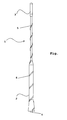
- Die Erfindung wird im Folgenden anhand eines Ausführungsbeispiels unter Bezugnahme auf die zugehörige Zeichnung näher erläutert. Die einzige Fig. der Zeichnung zeigt eine erfindungsgemäße Antenne.
- Die Antenne 1 umfasst im Wesentlichen einen Antennenfuß 2 sowie einen Antennenstab 3, mit dem elektromagnetische Wellen, beispielsweise eines Radiosenders, empfangen werden. Der Antennenfuß 2 ist vorzugsweise lösbar, insbesondere über eine Verschraubung, an einer Karosserie eines Kraftfahrzeugs befestigbar, wozu er an seiner freien Stirnseite einen Gewindeansatz 4 aufweist. Selbstverständlich sind über den Gewindeansatz 4 auch Mittel zur Herstellung einer elektrischen Verbindung zwischen dem Antennenstab 3 und einem Autoradio realisiert. Üblicherweise ist im Antennenfuß 2 eine Feder angeordnet, um den Antennenstab 3 flexibel zu haltern. Der Antennenfuß 2 ist mit einem flexiblen Material, u.a. in Form einer Gummimanschette, ummantelt, um die Feder gegen äußere Einflüsse zu schützen.
- Zur Unterdrückung von Windgeräuschen am Antennenstab 3 ist dieser in an sich bekannter Weise mit einem Draht 5 wendelförmig umwickelt, wobei durch diese künstliche Aufrauungen der Oberfläche des Antennenstabs 3 die periodische Ablösung von Luftwirbeln, die das eigentliche Windgeräusch verursachen, unterbunden ist.
- In der Oberfläche des Antennenfußes 2 ist eine wendelförmige Nut 6 ausgebildet, die vorzugsweise bereits bei der Produktion der den Antennenfuß 2 umhüllenden Gummimanschette ausgebildet wird, wobei durch die wendelförmige Nut 6 die Entstehung von Windgeräuschen, d.h. die periodische Wirbelablösung, am Antennenfuß 2 vermieden ist.
- Die Abmessungen der Nut 6 können entsprechend den Dimensionierungen des Drahtes 5 gewählt werden. Ebenso kann der Antennenstab 3 mit einer solchen Nut 6 versehen sein. Prinzipiell ist es möglich, dass die Nut 6 unterbrochen ausgeführt ist, im Wesentlichen in axialer Richtung verläuft oder in sich selbst geschlossen ist.
-
- 1.
- Antenne
- 2.
- Antennenfuß
- 3.
- Antennenstab
- 4.
- Gewindeansatz
- 5.
- Draht
- 6.
- Nut
Claims (6)
- Antenne für ein Kraftfahrzeug mit einem Antennenfuß (2) und einem Antennenstab (3), dadurch gekennzeichnet, dass in einer Oberfläche des Antennenfußes (2) und/oder des Antennenstabes (3) eine Nut (6) ausgebildet ist.
- Antenne nach Anspruch 1, dadurch gekennzeichnet, dass die Nut (6) wendelförmig ausgebildet ist.
- Antenne nach Anspruch 1 oder 2, dadurch gekennzeichnet, dass die Oberfläche des Antennenfußes (2) und/oder des Antennenstabes (3) von einer flexiblen Gummimanschette gebildet ist.
- Antenne nach einem der Ansprüche 1 bis 3, dadurch gekennzeichnet, dass der Antennenfuß (2) als Kunststoff-Spritzgussteil ausgeführt ist.
- Antenne nach einem der Ansprüche 1 bis 4, dadurch gekennzeichnet, dass im Antennenfuß (2) eine Feder vorgesehen ist.
- Antenne nach einem der Ansprüche 1 bis 5, dadurch gekennzeichnet, dass der Antennenfuß (2) lösbar am Dach des Kraftfahrzeugs zu befestigen ist, insbesondere über eine Verschraubung.
Applications Claiming Priority (1)
| Application Number | Priority Date | Filing Date | Title |
|---|---|---|---|
| DE102005061861A DE102005061861A1 (de) | 2005-12-23 | 2005-12-23 | Antenne für ein Kraftfahrzeug |
Publications (2)
| Publication Number | Publication Date |
|---|---|
| EP1801911A1 true EP1801911A1 (de) | 2007-06-27 |
| EP1801911B1 EP1801911B1 (de) | 2009-03-04 |
Family
ID=37908034
Family Applications (1)
| Application Number | Title | Priority Date | Filing Date |
|---|---|---|---|
| EP06024980A Not-in-force EP1801911B1 (de) | 2005-12-23 | 2006-12-02 | Antenne für ein Kraftfahrzeug |
Country Status (3)
| Country | Link |
|---|---|
| EP (1) | EP1801911B1 (de) |
| AT (1) | ATE424631T1 (de) |
| DE (2) | DE102005061861A1 (de) |
Cited By (2)
| Publication number | Priority date | Publication date | Assignee | Title |
|---|---|---|---|---|
| WO2018141496A1 (de) * | 2017-02-02 | 2018-08-09 | Hirschmann Car Communication Gmbh | Stabantenne mit antipfeifwendel |
| CN108493627A (zh) * | 2018-03-06 | 2018-09-04 | 湖南正申科技有限公司 | 一种用于甚低频透地通信的天线 |
Citations (5)
| Publication number | Priority date | Publication date | Assignee | Title |
|---|---|---|---|---|
| DE2846344A1 (de) * | 1978-10-25 | 1980-05-08 | Daimler Benz Ag | Windgeraeuscharme fahrzeugantenne |
| US4435713A (en) * | 1981-11-20 | 1984-03-06 | Motorola, Inc. | Whip antenna construction |
| EP0420567A1 (de) * | 1989-09-25 | 1991-04-03 | Harada Industry Co., Ltd. | Autoantenne und Verfahren zu deren Herstellung |
| JPH07193418A (ja) * | 1993-12-27 | 1995-07-28 | Harada Ind Co Ltd | 車載用アンテナ |
| US5917452A (en) * | 1996-02-29 | 1999-06-29 | Harada Industry Co., Ltd. | Noise reducing rod vehicle antenna |
Family Cites Families (4)
| Publication number | Priority date | Publication date | Assignee | Title |
|---|---|---|---|---|
| DE3205750C2 (de) * | 1982-02-18 | 1990-03-29 | Hans Kolbe & Co, 3202 Bad Salzdetfurth | Biegestück für einen Antennenstab einer Kfz-Antenne |
| DE3822664A1 (de) * | 1988-07-05 | 1989-02-16 | Kathrein Werke Kg | Stabfoermige fahrzeugantenne |
| FR2705497B1 (fr) * | 1993-05-17 | 1995-07-21 | Pizon Ernest | Antenne pour véhicule automobile. |
| ES2124640T3 (es) * | 1997-02-28 | 1999-02-01 | Top Glass Spa | Procedimiento de fabricacion de antenas de varilla extensible y antena de varilla extensible asi realizada. |
-
2005
- 2005-12-23 DE DE102005061861A patent/DE102005061861A1/de not_active Withdrawn
-
2006
- 2006-12-02 AT AT06024980T patent/ATE424631T1/de not_active IP Right Cessation
- 2006-12-02 EP EP06024980A patent/EP1801911B1/de not_active Not-in-force
- 2006-12-02 DE DE502006003002T patent/DE502006003002D1/de active Active
Patent Citations (5)
| Publication number | Priority date | Publication date | Assignee | Title |
|---|---|---|---|---|
| DE2846344A1 (de) * | 1978-10-25 | 1980-05-08 | Daimler Benz Ag | Windgeraeuscharme fahrzeugantenne |
| US4435713A (en) * | 1981-11-20 | 1984-03-06 | Motorola, Inc. | Whip antenna construction |
| EP0420567A1 (de) * | 1989-09-25 | 1991-04-03 | Harada Industry Co., Ltd. | Autoantenne und Verfahren zu deren Herstellung |
| JPH07193418A (ja) * | 1993-12-27 | 1995-07-28 | Harada Ind Co Ltd | 車載用アンテナ |
| US5917452A (en) * | 1996-02-29 | 1999-06-29 | Harada Industry Co., Ltd. | Noise reducing rod vehicle antenna |
Cited By (5)
| Publication number | Priority date | Publication date | Assignee | Title |
|---|---|---|---|---|
| WO2018141496A1 (de) * | 2017-02-02 | 2018-08-09 | Hirschmann Car Communication Gmbh | Stabantenne mit antipfeifwendel |
| KR20190104245A (ko) * | 2017-02-02 | 2019-09-06 | 히르쉬만 카 커뮤니케이션 게엠베하 | 휘슬-방지 코일을 갖는 로드 안테나 |
| CN110291684A (zh) * | 2017-02-02 | 2019-09-27 | 赫思曼汽车通讯有限公司 | 具有防啸叫线圈的杆状天线 |
| JP2020506621A (ja) * | 2017-02-02 | 2020-02-27 | ヒルシュマン カー コミュニケーション ゲゼルシャフト ミット ベシュレンクテル ハフツングHirschmann Car Communication GmbH | ホイッスル防止コイルを有するロッドアンテナ |
| CN108493627A (zh) * | 2018-03-06 | 2018-09-04 | 湖南正申科技有限公司 | 一种用于甚低频透地通信的天线 |
Also Published As
| Publication number | Publication date |
|---|---|
| ATE424631T1 (de) | 2009-03-15 |
| EP1801911B1 (de) | 2009-03-04 |
| DE102005061861A1 (de) | 2007-06-28 |
| DE502006003002D1 (de) | 2009-04-16 |
Similar Documents
| Publication | Publication Date | Title |
|---|---|---|
| EP1830071B1 (de) | Kunstoffverdichtergehäuse | |
| EP2855243B1 (de) | Baugruppe zum bilden eines luftleitelements für ein kraftfahrzeug | |
| DE10317305A1 (de) | Abdeckung für ein Aggregat im Motorraum eines Kraftfahrzeuges | |
| DE102011015522A1 (de) | Kunststoffkörper und Fertigungsanlage zur Herstellung eines Kunststoffkörpers | |
| EP0048029B1 (de) | Rutenangel mit Angelschnur-Führungsring und Verfahren zu ihrer Herstellung | |
| WO2008071481A1 (de) | Wischblatt | |
| DE2714020A1 (de) | Zahnrad aus kunststoff und verfahren zu seiner herstellung | |
| EP1801911B1 (de) | Antenne für ein Kraftfahrzeug | |
| DE69020282T2 (de) | Autoantenne und Verfahren zu deren Herstellung. | |
| DE102010063143A1 (de) | Scheibenwischvorrichtung für ein Kraftfahrzeug | |
| EP2666384A1 (de) | Applikatoreinheit für eine Kosmetikeinheit sowie Kosmetikeinheit mit einer derartigen Applikatoreinheit | |
| DE102017218901A1 (de) | Vorrichtung zur Abstützung eines Schutzrohrs gegen das Behälterrohr eines Schwingungsdämpfers | |
| EP3374249B1 (de) | Strukturbauteil für ein kraftfahrzeug | |
| DE102013001129A1 (de) | Luftauslass und Fahrzeug mit einem derartigen Luftauslass | |
| DE69006703T2 (de) | Scharnier für eine Sonnenblende eines Kraftfahrzeuges. | |
| EP2741905B1 (de) | Befestigung eines blasformbauteils | |
| DE102009010950A1 (de) | Lamelle sowie Verfahren zur Herstellung der Lamelle | |
| DE102017102050A1 (de) | Stabantenne mit Antipfeifwendel | |
| DE102013000073A1 (de) | Windabweiser sowie Verfahren zur Herstellung eines Windabweisers | |
| DE102004017761A1 (de) | Vibrationsgedämpfter Handgriff für ein Elektrohandwerkzeuggerät | |
| DE102009011895A1 (de) | Radlaufverkleidung für einen Kotflügel eines Fahrzeugs | |
| DD151523A5 (de) | Tonabnehmer mit beweglichem magneten und verfahren zu seiner herstellung | |
| DE102013013169A1 (de) | Türinnenverkleidung für eine Fahrzeugtür | |
| DE102004056272A1 (de) | Medienführendes Hohlbauteil | |
| DE102011076161A1 (de) | Lagerschale für ein Kugelgelenk |
Legal Events
| Date | Code | Title | Description |
|---|---|---|---|
| PUAI | Public reference made under article 153(3) epc to a published international application that has entered the european phase |
Free format text: ORIGINAL CODE: 0009012 |
|
| AK | Designated contracting states |
Kind code of ref document: A1 Designated state(s): AT BE BG CH CY CZ DE DK EE ES FI FR GB GR HU IE IS IT LI LT LU LV MC NL PL PT RO SE SI SK TR |
|
| AX | Request for extension of the european patent |
Extension state: AL BA HR MK YU |
|
| 17P | Request for examination filed |
Effective date: 20071227 |
|
| 17Q | First examination report despatched |
Effective date: 20080201 |
|
| AKX | Designation fees paid |
Designated state(s): AT BE BG CH CY CZ DE DK EE ES FI FR GB GR HU IE IS IT LI LT LU LV MC NL PL PT RO SE SI SK TR |
|
| GRAP | Despatch of communication of intention to grant a patent |
Free format text: ORIGINAL CODE: EPIDOSNIGR1 |
|
| GRAP | Despatch of communication of intention to grant a patent |
Free format text: ORIGINAL CODE: EPIDOSNIGR1 |
|
| GRAS | Grant fee paid |
Free format text: ORIGINAL CODE: EPIDOSNIGR3 |
|
| GRAA | (expected) grant |
Free format text: ORIGINAL CODE: 0009210 |
|
| AK | Designated contracting states |
Kind code of ref document: B1 Designated state(s): AT BE BG CH CY CZ DE DK EE ES FI FR GB GR HU IE IS IT LI LT LU LV MC NL PL PT RO SE SI SK TR |
|
| REG | Reference to a national code |
Ref country code: GB Ref legal event code: FG4D Free format text: NOT ENGLISH |
|
| REG | Reference to a national code |
Ref country code: CH Ref legal event code: EP |
|
| REG | Reference to a national code |
Ref country code: GB Ref legal event code: 732E Free format text: REGISTERED BETWEEN 20090305 AND 20090311 Ref country code: IE Ref legal event code: FG4D Free format text: LANGUAGE OF EP DOCUMENT: GERMAN |
|
| REF | Corresponds to: |
Ref document number: 502006003002 Country of ref document: DE Date of ref document: 20090416 Kind code of ref document: P |
|
| PG25 | Lapsed in a contracting state [announced via postgrant information from national office to epo] |
Ref country code: SI Free format text: LAPSE BECAUSE OF FAILURE TO SUBMIT A TRANSLATION OF THE DESCRIPTION OR TO PAY THE FEE WITHIN THE PRESCRIBED TIME-LIMIT Effective date: 20090304 Ref country code: NL Free format text: LAPSE BECAUSE OF FAILURE TO SUBMIT A TRANSLATION OF THE DESCRIPTION OR TO PAY THE FEE WITHIN THE PRESCRIBED TIME-LIMIT Effective date: 20090304 Ref country code: LT Free format text: LAPSE BECAUSE OF FAILURE TO SUBMIT A TRANSLATION OF THE DESCRIPTION OR TO PAY THE FEE WITHIN THE PRESCRIBED TIME-LIMIT Effective date: 20090304 Ref country code: FI Free format text: LAPSE BECAUSE OF FAILURE TO SUBMIT A TRANSLATION OF THE DESCRIPTION OR TO PAY THE FEE WITHIN THE PRESCRIBED TIME-LIMIT Effective date: 20090304 |
|
| NLV1 | Nl: lapsed or annulled due to failure to fulfill the requirements of art. 29p and 29m of the patents act | ||
| PG25 | Lapsed in a contracting state [announced via postgrant information from national office to epo] |
Ref country code: PL Free format text: LAPSE BECAUSE OF FAILURE TO SUBMIT A TRANSLATION OF THE DESCRIPTION OR TO PAY THE FEE WITHIN THE PRESCRIBED TIME-LIMIT Effective date: 20090304 Ref country code: LV Free format text: LAPSE BECAUSE OF FAILURE TO SUBMIT A TRANSLATION OF THE DESCRIPTION OR TO PAY THE FEE WITHIN THE PRESCRIBED TIME-LIMIT Effective date: 20090304 Ref country code: SE Free format text: LAPSE BECAUSE OF FAILURE TO SUBMIT A TRANSLATION OF THE DESCRIPTION OR TO PAY THE FEE WITHIN THE PRESCRIBED TIME-LIMIT Effective date: 20090604 |
|
| REG | Reference to a national code |
Ref country code: IE Ref legal event code: FD4D |
|
| PG25 | Lapsed in a contracting state [announced via postgrant information from national office to epo] |
Ref country code: IE Free format text: LAPSE BECAUSE OF FAILURE TO SUBMIT A TRANSLATION OF THE DESCRIPTION OR TO PAY THE FEE WITHIN THE PRESCRIBED TIME-LIMIT Effective date: 20090304 Ref country code: EE Free format text: LAPSE BECAUSE OF FAILURE TO SUBMIT A TRANSLATION OF THE DESCRIPTION OR TO PAY THE FEE WITHIN THE PRESCRIBED TIME-LIMIT Effective date: 20090304 Ref country code: ES Free format text: LAPSE BECAUSE OF FAILURE TO SUBMIT A TRANSLATION OF THE DESCRIPTION OR TO PAY THE FEE WITHIN THE PRESCRIBED TIME-LIMIT Effective date: 20090615 Ref country code: PT Free format text: LAPSE BECAUSE OF FAILURE TO SUBMIT A TRANSLATION OF THE DESCRIPTION OR TO PAY THE FEE WITHIN THE PRESCRIBED TIME-LIMIT Effective date: 20090818 Ref country code: CZ Free format text: LAPSE BECAUSE OF FAILURE TO SUBMIT A TRANSLATION OF THE DESCRIPTION OR TO PAY THE FEE WITHIN THE PRESCRIBED TIME-LIMIT Effective date: 20090304 |
|
| REG | Reference to a national code |
Ref country code: GB Ref legal event code: 732E Free format text: REGISTERED BETWEEN 20091029 AND 20091104 |
|
| PG25 | Lapsed in a contracting state [announced via postgrant information from national office to epo] |
Ref country code: RO Free format text: LAPSE BECAUSE OF FAILURE TO SUBMIT A TRANSLATION OF THE DESCRIPTION OR TO PAY THE FEE WITHIN THE PRESCRIBED TIME-LIMIT Effective date: 20090304 Ref country code: IS Free format text: LAPSE BECAUSE OF FAILURE TO SUBMIT A TRANSLATION OF THE DESCRIPTION OR TO PAY THE FEE WITHIN THE PRESCRIBED TIME-LIMIT Effective date: 20090704 Ref country code: SK Free format text: LAPSE BECAUSE OF FAILURE TO SUBMIT A TRANSLATION OF THE DESCRIPTION OR TO PAY THE FEE WITHIN THE PRESCRIBED TIME-LIMIT Effective date: 20090304 |
|
| REG | Reference to a national code |
Ref country code: GB Ref legal event code: 732E Free format text: REGISTERED BETWEEN 20091105 AND 20091111 |
|
| PLBE | No opposition filed within time limit |
Free format text: ORIGINAL CODE: 0009261 |
|
| STAA | Information on the status of an ep patent application or granted ep patent |
Free format text: STATUS: NO OPPOSITION FILED WITHIN TIME LIMIT |
|
| PG25 | Lapsed in a contracting state [announced via postgrant information from national office to epo] |
Ref country code: DK Free format text: LAPSE BECAUSE OF FAILURE TO SUBMIT A TRANSLATION OF THE DESCRIPTION OR TO PAY THE FEE WITHIN THE PRESCRIBED TIME-LIMIT Effective date: 20090304 Ref country code: BG Free format text: LAPSE BECAUSE OF FAILURE TO SUBMIT A TRANSLATION OF THE DESCRIPTION OR TO PAY THE FEE WITHIN THE PRESCRIBED TIME-LIMIT Effective date: 20090604 |
|
| 26N | No opposition filed |
Effective date: 20091207 |
|
| BERE | Be: lapsed |
Owner name: GM GLOBAL TECHNOLOGY OPERATIONS, INC. Effective date: 20091231 |
|
| PG25 | Lapsed in a contracting state [announced via postgrant information from national office to epo] |
Ref country code: MC Free format text: LAPSE BECAUSE OF NON-PAYMENT OF DUE FEES Effective date: 20100701 |
|
| PG25 | Lapsed in a contracting state [announced via postgrant information from national office to epo] |
Ref country code: BE Free format text: LAPSE BECAUSE OF NON-PAYMENT OF DUE FEES Effective date: 20091231 Ref country code: GR Free format text: LAPSE BECAUSE OF FAILURE TO SUBMIT A TRANSLATION OF THE DESCRIPTION OR TO PAY THE FEE WITHIN THE PRESCRIBED TIME-LIMIT Effective date: 20090605 |
|
| PG25 | Lapsed in a contracting state [announced via postgrant information from national office to epo] |
Ref country code: IT Free format text: LAPSE BECAUSE OF FAILURE TO SUBMIT A TRANSLATION OF THE DESCRIPTION OR TO PAY THE FEE WITHIN THE PRESCRIBED TIME-LIMIT Effective date: 20090304 |
|
| PG25 | Lapsed in a contracting state [announced via postgrant information from national office to epo] |
Ref country code: LU Free format text: LAPSE BECAUSE OF NON-PAYMENT OF DUE FEES Effective date: 20091202 |
|
| REG | Reference to a national code |
Ref country code: DE Ref legal event code: R081 Ref document number: 502006003002 Country of ref document: DE Owner name: GM GLOBAL TECHNOLOGY OPERATIONS LLC (N. D. GES, US Free format text: FORMER OWNER: GM GLOBAL TECHNOLOGY OPERATIONS, INC., DETROIT, MICH., US Effective date: 20110323 |
|
| PG25 | Lapsed in a contracting state [announced via postgrant information from national office to epo] |
Ref country code: AT Free format text: LAPSE BECAUSE OF NON-PAYMENT OF DUE FEES Effective date: 20091202 |
|
| PG25 | Lapsed in a contracting state [announced via postgrant information from national office to epo] |
Ref country code: HU Free format text: LAPSE BECAUSE OF FAILURE TO SUBMIT A TRANSLATION OF THE DESCRIPTION OR TO PAY THE FEE WITHIN THE PRESCRIBED TIME-LIMIT Effective date: 20090905 |
|
| REG | Reference to a national code |
Ref country code: CH Ref legal event code: PL |
|
| PG25 | Lapsed in a contracting state [announced via postgrant information from national office to epo] |
Ref country code: TR Free format text: LAPSE BECAUSE OF FAILURE TO SUBMIT A TRANSLATION OF THE DESCRIPTION OR TO PAY THE FEE WITHIN THE PRESCRIBED TIME-LIMIT Effective date: 20090304 |
|
| PG25 | Lapsed in a contracting state [announced via postgrant information from national office to epo] |
Ref country code: CY Free format text: LAPSE BECAUSE OF FAILURE TO SUBMIT A TRANSLATION OF THE DESCRIPTION OR TO PAY THE FEE WITHIN THE PRESCRIBED TIME-LIMIT Effective date: 20090304 |
|
| PG25 | Lapsed in a contracting state [announced via postgrant information from national office to epo] |
Ref country code: LI Free format text: LAPSE BECAUSE OF NON-PAYMENT OF DUE FEES Effective date: 20101231 Ref country code: CH Free format text: LAPSE BECAUSE OF NON-PAYMENT OF DUE FEES Effective date: 20101231 |
|
| REG | Reference to a national code |
Ref country code: FR Ref legal event code: PLFP Year of fee payment: 10 |
|
| PGFP | Annual fee paid to national office [announced via postgrant information from national office to epo] |
Ref country code: GB Payment date: 20151202 Year of fee payment: 10 |
|
| PGFP | Annual fee paid to national office [announced via postgrant information from national office to epo] |
Ref country code: FR Payment date: 20151110 Year of fee payment: 10 |
|
| GBPC | Gb: european patent ceased through non-payment of renewal fee |
Effective date: 20161202 |
|
| REG | Reference to a national code |
Ref country code: FR Ref legal event code: ST Effective date: 20170831 |
|
| PG25 | Lapsed in a contracting state [announced via postgrant information from national office to epo] |
Ref country code: FR Free format text: LAPSE BECAUSE OF NON-PAYMENT OF DUE FEES Effective date: 20170102 |
|
| PG25 | Lapsed in a contracting state [announced via postgrant information from national office to epo] |
Ref country code: GB Free format text: LAPSE BECAUSE OF NON-PAYMENT OF DUE FEES Effective date: 20161202 |
|
| PGFP | Annual fee paid to national office [announced via postgrant information from national office to epo] |
Ref country code: DE Payment date: 20181120 Year of fee payment: 13 |
|
| REG | Reference to a national code |
Ref country code: DE Ref legal event code: R119 Ref document number: 502006003002 Country of ref document: DE |
|
| PG25 | Lapsed in a contracting state [announced via postgrant information from national office to epo] |
Ref country code: DE Free format text: LAPSE BECAUSE OF NON-PAYMENT OF DUE FEES Effective date: 20200701 |