EP1801328B1 - Porte avec un dispositif de verrouillage surveillé et procédé d'utilisation d'un tel porte - Google Patents
Porte avec un dispositif de verrouillage surveillé et procédé d'utilisation d'un tel porte Download PDFInfo
- Publication number
- EP1801328B1 EP1801328B1 EP06124034.7A EP06124034A EP1801328B1 EP 1801328 B1 EP1801328 B1 EP 1801328B1 EP 06124034 A EP06124034 A EP 06124034A EP 1801328 B1 EP1801328 B1 EP 1801328B1
- Authority
- EP
- European Patent Office
- Prior art keywords
- sensor
- transponder
- window
- datum
- processing unit
- Prior art date
- Legal status (The legal status is an assumption and is not a legal conclusion. Google has not performed a legal analysis and makes no representation as to the accuracy of the status listed.)
- Active
Links
Images


Classifications
-
- E—FIXED CONSTRUCTIONS
- E05—LOCKS; KEYS; WINDOW OR DOOR FITTINGS; SAFES
- E05C—BOLTS OR FASTENING DEVICES FOR WINGS, SPECIALLY FOR DOORS OR WINDOWS
- E05C9/00—Arrangements of simultaneously actuated bolts or other securing devices at well-separated positions on the same wing
- E05C9/18—Details of fastening means or of fixed retaining means for the ends of bars
- E05C9/1825—Fastening means
- E05C9/1833—Fastening means performing sliding movements
- E05C9/185—Fastening means performing sliding movements parallel with actuating bar
- E05C9/1858—Fastening means performing sliding movements parallel with actuating bar of the roller bolt type
-
- E—FIXED CONSTRUCTIONS
- E05—LOCKS; KEYS; WINDOW OR DOOR FITTINGS; SAFES
- E05B—LOCKS; ACCESSORIES THEREFOR; HANDCUFFS
- E05B45/00—Alarm locks
- E05B45/06—Electric alarm locks
- E05B45/08—Electric alarm locks with contact making inside the lock or in the striking plate
- E05B45/083—Electric alarm locks with contact making inside the lock or in the striking plate with contact making either in the striking plate or by movement of the bolt relative to the striking plate
-
- E—FIXED CONSTRUCTIONS
- E05—LOCKS; KEYS; WINDOW OR DOOR FITTINGS; SAFES
- E05C—BOLTS OR FASTENING DEVICES FOR WINGS, SPECIALLY FOR DOORS OR WINDOWS
- E05C9/00—Arrangements of simultaneously actuated bolts or other securing devices at well-separated positions on the same wing
- E05C9/18—Details of fastening means or of fixed retaining means for the ends of bars
- E05C9/1808—Keepers
-
- E—FIXED CONSTRUCTIONS
- E05—LOCKS; KEYS; WINDOW OR DOOR FITTINGS; SAFES
- E05B—LOCKS; ACCESSORIES THEREFOR; HANDCUFFS
- E05B47/00—Operating or controlling locks or other fastening devices by electric or magnetic means
- E05B2047/0048—Circuits, feeding, monitoring
- E05B2047/0067—Monitoring
- E05B2047/0069—Monitoring bolt position
Definitions
- the present invention relates to a window or the like with a monitorable lock arrangement for monitoring an opening state and / or a closed position of two relatively movable parts with a frame and a wing as relatively movable parts.
- the invention further relates to a method of operating such a window or the like with a monitorable latching arrangement.
- Such arrangements are used in the private or commercial sector, especially for purposes of property protection or burglary detection.
- Such arrangements or devices are also required to be able to meet, for a private or commercial property, usually a property, a total of a certain safety standard associated with the performance and functionality of such and other arrangements such that the owner or owner of such Object of the use of agreed on the respective security standard insurance conditions in question.
- Such a monitorable latching arrangement is known, for example from the EP 1 043 461 A1 known.
- a closure pin is connected via an adapter rail with a sensor device.
- the sensor device can therefore detect the position of the locking bolt only indirectly.
- a security sensor in which a coded signal is generated by a responder.
- the coding of the signal contributes to the manipulation security.
- This embodiment of a monitoring arrangement is not yet entirely optimal in that the possibility of manipulating the signals supplied by the monitoring arrangement exists when e.g. a window is found in an open position for a short period of time and a permanent magnet is left in the region of the sensor arranged in the strike plate.
- the monitoring arrangement detects the magnetic field of this permanent magnet and accordingly emits a signal which normally indicates a proper closed position of the window or door.
- a burglary alarm system or the like neither such manipulations nor the actual open state of manipulated windows or doors can be seen. In this way, e.g. Persons who, at a certain time, have access to an object, e.g. a commercial property, have, and are controlled upon entering and leaving the property by a plant protection, provide a possibility for a later, unguarded access to the object, which should be prevented.
- the invention is based on the recognition that a clear date can be imprinted on a transponder, which emits it either permanently or on the basis of external activation and can then be picked up by a sensor and evaluated either by a sensor itself or by an internal or external downstream processing unit.
- a clear date can be imprinted on a transponder, which emits it either permanently or on the basis of external activation and can then be picked up by a sensor and evaluated either by a sensor itself or by an internal or external downstream processing unit.
- the advantage of the invention is the high security against manipulation due to the fact that a real data transmission takes place by means of the transponder, wherein the transmitted date checked for plausibility and / or authenticity by the remote station, so the sensor or a processing unit downstream of the sensor or externally becomes. Since that is the Transponder embossed date is neither directly recognizable nor easy to read, the risk of manipulation is significantly reduced, which would only be possible if third parties would emulate the sensor provided in the context. This is associated with considerable, but especially temporal and equipment technical effort, so that the probability that this could happen unnoticed in an otherwise monitored object can be considered extremely low. Furthermore, the risk of manipulation is reduced by encrypting the transmission of data between the transponder and the remote station, so that unwanted read-out can be virtually ruled out.
- the closing plate in juxtaposed positions is assigned a plurality of sensors.
- This not only a single position of the monitored window, the monitored door or the like can be monitored but one of the number of sensors corresponding number of positions.
- monitoring windows come as a monitored positions z. B. an open position (first sensor), a closed position (second sensor) and a tilted position (third sensor) into consideration, where "open position” means that the sash lies in the frame, the wing is not yet locked and wherein “closed position” accordingly means that the wing rests in the frame and is locked.
- a “fourth position” namely, when the window sash is pivoted out of the frame, it can be seen that none of the sensors provides a signal.
- the number of positions z. B. increased by a parallel shutdown, therefore, the number of sensors would have to be increased.
- a communicative connection to a bus system is provided for the local and central processing unit, wherein the local processing unit downstream of the sensor forwards the received data via a bus system to the central processing unit.
- the local sensor In the outsourcing of both parts of the processing functionality (digitization and authentication) in an external central processing unit, the local sensor is modified so that he himself the date of the transponder read out by him over a communicative connection z. B. forwards a bus system to the external, central processing unit.
- the senor comprises a sensor winding acting as an antenna and that the antenna is provided both for emitting an electromagnetic field for powering the transponder and for detecting a date emitted by the transponder date in the form of an electromagnetic signal.
- the antenna is provided both for emitting an electromagnetic field for powering the transponder and for detecting a date emitted by the transponder date in the form of an electromagnetic signal.
- the transmission of the date takes place in the form of an electromagnetic signal between the transponder and the sensor or the antenna in an encrypted form. This makes the information transmitted - the date - inaccessible to third parties. Only the authorized recipient, in our case the authorized sensor is able to read the transmitted information of the transponder.
- the encryption prevents the reading of the date by unauthorized third parties who could use this for the reconstruction of the transponder and its misuse.
- the date can be evaluated by the sensor or by a processing unit connected internally or externally to the sensor.
- this includes corresponding processing functionality that makes such an evaluation possible.
- the processing functionality can also be connected downstream of the actual sensor.
- the processing functionality ie a corresponding device, e.g. a microprocessor with transceiver IC, in the frame, in particular together with the sensor below the striker, be arranged.
- the transceiver IC preferably takes at least the digitization of the electromagnetic wave, so as analog information, received date.
- the microprocessor may also already check or pre-check the received date, e.g. on the basis of a checksum or the like or on the basis of a predefined schedule for the date.
- the processing functionality in particular the microprocessor, can also be used to authenticate the date on the basis of reference data stored in a database or can be stored.
- This part of the processing functionality can also be outsourced to an external, central processing unit, such that for an object, each local processing functionality (eg transceiver IC) arranged in the context of a window, a door or the like stores the respectively received date (if necessary). after a preliminary check of the type described above) to a central processing unit for evaluating the date (authentication) forwards.
- each local processing functionality eg transceiver IC
- a central processing unit for a preliminary check of the type described above
- the authentication is preferably done by comparison with in a database, to which the processing unit has access, depositable reference data.
- the reference data used in the database is either each date approved for the object, an education rule that includes all the data permitted for the object, or any other inspection scheme that includes all authorized data.
- the data emitted by the transponder is only picked up by the respective sensor if the transponder is located in close proximity to the sensor, in the case of a monitored window, e.g. then when the wing rests in the frame profile or at least approximately rests. This is achieved with a suitably directed radiation characteristic of the transponder. This ensures that the sensor receives the data emitted by the transponder when, and only if, in the case of a monitored window, the vane in the o.g. Art is in the frame and / or when the locking pin is in a defined position.
- the transponder is supplied by the sensor in its function as a source of electromagnetic field with electrical energy and the transponder correspondingly radiates the date only when it is in a vicinity of the sensor, which allows such a power supply.
- This correlation allows a defined activation of the transponder only when it enters a predetermined near range of the sensor.
- the near zone of the sensor is essentially defined by the shape of the electromagnetic field emitted by the sensor, that is to say by the directional characteristic of the antenna component of the sensor.
- the directional characteristic of the sensor when activating the transponder and the directional characteristic of the transponder when sending the date of the close range so the associated verification whether the locking pin is in a defined position to the strike plate, so accurately defined that False evaluations are almost impossible.
- a respective signal is delivered. For example, an "ok signal" can be given if every received date has been recognized as approved. Alternatively, an error signal can be issued if at least one received date has been detected as not approved.
- mixed forms of such signaling are also conceivable and included in the invention, in which it can be provided, for example, that as long as each received date is recognized as approved, the "ok signal" is emitted and that, as soon as at least one received date is recognized as not permitted, on the one hand an error signal and on the other a signal to identify the error-causing window (or the door or the like) which is formed on the basis of an identifier of the local sensor transmitted by the sensor to the central processing unit during each data transfer, eg in the form of its address on the bus.
- this special operating mode is possible, for example, by a master transponder or programming transponder, which is carried along by an authorized person and brought to the locking arrangement, so that the "learning mode" is activated.
- the new transponder date can be transferred to the database.
- the master transponder carries a date which is recognized by the processing unit and causes it to switch to the "learning mode".
- the activation of the "learning mode” can also be triggered centrally via the central processing unit, so that the new data from one, several or all transponders can be read into the database.
- the invention also relates to a monitoring device, that is to say an overall system comprising a number of windows or the like with monitorable latching arrangements and at least one external processing unit (central processing unit), eg in the form of a burglar alarm system or the like.
- Each locking arrangement is communicatively, in particular via a bus, connected to the central processing unit.
- the central processing unit can centrally monitor a plurality of interlocking arrangements by, for example, accessing the central processing unit accessing a database of reference data for individual authentication Locking arrangements received data and in that the central processing unit upon receipt of a date from one of the locking arrangements performs an authentication of the received date based on the stored in the database reference data.
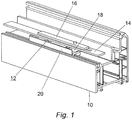
- Fig. 1 shows a section of a section of a frame profile 10, hereinafter referred to briefly as a frame 10, a window not shown with a monitorable latch assembly 12 according to the invention for reasons of clarity, a wing of the window is not shown.
- a wing of the window is not shown.
- the drive rod 16 carries a locking pin 18th face plate 14, drive rod 16 and locking pin 18 are summarized under the term locking mechanism.
- the locking pin 18 is provided for engagement in a frame 10 associated with the strike plate 20. When the locking pin 18 is out of engagement with the striking plate 20, the wing can swing out of the frame 10 and open the window.
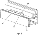
- Fig. 2 shows in this context in the same perspective as in Fig. 1 It can be seen that the locking pin 18 engages for locking the wing in an engagement recess 22 of the striking plate 20 and prevents pivoting of the window sash in this position.
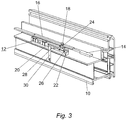
- Fig. 3 shows in the same perspective as Fig.1 the frame 10 in an additional longitudinal section through the frame 10 and the locking assembly 12.
- the locking pin 18 includes a vertically adjusted transponder 24 here.
- This is for the delivery of a date, that is, a unique identifier, provided by the closing plate 20 associated antenna 26, which thus acts as a sensor for the radiated from the transponder 24 date added.
- the antenna (the terms antenna 26 and sensor are used interchangeably hereinafter) is assigned to an internal processing unit 28 in the form of evaluation electronics comprising a transceiver IC and a microprocessor.
- the internal processing unit 28 is communicatively connectable via a bus line 30 to an external burglar alarm unit (not shown).
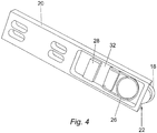
- Fig. 4 shows only the strike plate 20 in a view of the bottom, so in a view of that side, which faces the frame 10 in the installed state. Visible is also the sensor 26 or the antenna 26. This is electrically connected to a circuit board 32, on which the internal processing unit 28 is shown schematically in the form of a microprocessor or the like.
- the representation of the bus line 30 is missing in Fig. 4 ,
- the half-inserted into the engagement recess 22 of the strike plate 20 locking pin 18 is also recognizable and it can be seen that when the locking pin 18 is completely inserted into the engagement recess, this is directly above the antenna 26 - the sensor 26 - comes to rest, so that a reception of the im Locking pin 18 transponder 24 remote date contained by the sensor 26 is possible.
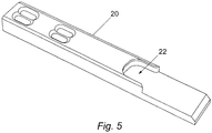
- Fig. 5 shows a preferred embodiment of the striking plate 20, wherein the strike plate 20 is extended in this embodiment in the region of the engagement recess 22.
- FIG. 6 the underside of this extended strike plate 20, wherein it can be seen that this strike plate 20, in contrast to the in Fig. 4 shown lock plate 20, not only a sensor 26 but a plurality of sensors 26, in the example shown, three sensors 26, are assigned.
- the position of each sensor 26 on the underside of the extended strike plate 20 corresponds to a corresponding position of the locking bolt 18 at different positions of the window (open position, closed position, tilt position).
- Fig. 7 shows an enlarged view with partially transparent components shown the locking pin 18 and the transponder arranged therein 24.
- a transparent here shown outer jacket of the transponder 18 is made of a material having sufficient to ensure the function of the locking pin as a locking means strength.
- the transponder 24 is inserted into a recess of the downwardly open shell of the locking bolt 18 and fixed in this position, for example by a potting compound 34. Notwithstanding the in Fig. 7 illustrated vertical orientation of the transponder 24 in the locking pin 18 are also other orientations, such as a horizontal orientation, conceivable.
Claims (12)
- Fenêtre ou similaire, avec un agencement de verrouillage pouvant être surveillé, dont le vantail est supporté de façon pivotante sur un cadre (10), un mécanisme de verrouillage avec un pêne (18) destiné à s'engager dans une gâche (20) affectée au cadre (10) étant affecté au vantail, et l'engagement du pêne (18) dans la gâche (20) pouvant être détecté, un transpondeur (24) étant affecté au pêne (18), et un capteur (26) prévu pour la coopération avec le transpondeur (24) étant affecté à la gâche (20), caractérisée en ce qu'une pluralité de capteurs (26) sont affectés à la gâche (20) dans des positions juxtaposées les unes aux autres, en ce que le transpondeur (24) est disposé dans le pêne (18) et en ce qu'il est prévu une liaison de communication avec un système de bus, le capteur (26) lui-même ou une unité de traitement (transceiver-IC) montée en aval du capteur (26) étant prévue(e) pour le transfert de la donnée reçue vers le système de bus.
- Fenêtre ou similaire selon la revendication 1, le capteur (26) comprenant un bobinage de capteur fonctionnant en tant qu'antenne, et l'antenne étant prévue aussi bien pour le rayonnement d'un champ électromagnétique pour l'alimentation en énergie du transpondeur (24) que pour la détection d'un signal - donnée - électromagnétique émis par le transpondeur (24).
- Fenêtre ou similaire selon la revendication 2, une transmission de la donnée entre le transpondeur (24) et le capteur (26) étant cryptée.
- Fenêtre ou similaire selon la revendication 3, la donnée pouvant être analysée par le capteur (26) ou par une unité de traitement montée en aval du capteur (26) de façon interne ou externe.
- Fenêtre ou similaire selon la revendication 4, l'analyse de la donnée comprenant une comparaison avec des données de référence pouvant être stockées dans une base de données.
- Procédé de fonctionnement d'une fenêtre ou similaire selon l'une ou plusieurs des revendications précédentes, une donnée émise par le transpondeur (24) étant enregistrée par le capteur (26) quand le transpondeur (24) se situe dans une zone proche du capteur (26).
- Procédé selon la revendication 6, le transpondeur (24) étant alimenté en énergie électrique par le capteur (26) dans sa fonction en tant que source d'un champ électromagnétique, et le transpondeur (24) n'émettant en conséquence la donnée que s'il se trouve dans une zone proche du capteur (26) qui permet une telle alimentation en énergie.
- Procédé selon la revendication 6 ou 7, une unité de traitement montée en aval du capteur (26) de façon interne ou externe vérifiant la donnée reçue, en particulier à l'aide de données de référence stockées dans une base de données, et un signal en ce sens étant délivré en fonction du résultat de la vérification.
- Procédé selon la revendication 8, un mode de fonctionnement spécial étant prévu pour le transfert vers la base de données de la donnée émise par le transpondeur (24).
- Procédé selon la revendication 9, une activation du mode de fonctionnement spécial étant effectuée par un transpondeur maître.
- Système de surveillance avec au moins une fenêtre ou similaire selon l'une ou plusieurs des revendications 1 à 5, chaque agencement de verrouillage étant raccordé en communication à une unité de traitement centrale par le biais d'un système de bus, l'unité de traitement centrale ayant accès à une base de données avec des données de référence pour l'authentification de données reçues pendant le fonctionnement en provenance de différents agencements de verrouillage.
- Procédé de fonctionnement d'un agencement de surveillance selon la revendication 11, l'unité de traitement centrale procédant, lors de la réception d'une donnée en provenance de l'un des agencements de verrouillage, à une authentification de la donnée reçue à l'aide des données de référence stockées dans la base de données.
Applications Claiming Priority (1)
| Application Number | Priority Date | Filing Date | Title |
|---|---|---|---|
| DE102005000182A DE102005000182A1 (de) | 2005-12-13 | 2005-12-13 | Überwachbare Verriegelungsanordnung für ein Fenster, eine Türe oder dergleichen und Verfahren zum Betrieb einer solchen Verriegelungsanordnung |
Publications (3)
| Publication Number | Publication Date |
|---|---|
| EP1801328A2 EP1801328A2 (fr) | 2007-06-27 |
| EP1801328A3 EP1801328A3 (fr) | 2010-04-21 |
| EP1801328B1 true EP1801328B1 (fr) | 2018-03-21 |
Family
ID=37946458
Family Applications (1)
| Application Number | Title | Priority Date | Filing Date |
|---|---|---|---|
| EP06124034.7A Active EP1801328B1 (fr) | 2005-12-13 | 2006-11-14 | Porte avec un dispositif de verrouillage surveillé et procédé d'utilisation d'un tel porte |
Country Status (2)
| Country | Link |
|---|---|
| EP (1) | EP1801328B1 (fr) |
| DE (1) | DE102005000182A1 (fr) |
Families Citing this family (12)
| Publication number | Priority date | Publication date | Assignee | Title |
|---|---|---|---|---|
| DE102008001194A1 (de) * | 2008-04-15 | 2009-10-22 | Aug. Winkhaus Gmbh & Co. Kg | Überwachungseinrichtung eines Treibstangenbeschlages eines Fensters |
| IT1393892B1 (it) * | 2009-03-31 | 2012-05-17 | Profilati Spa | Dispositivo per la generazione di un segnale di sicurezza applicabile ad un serramento e serramento montante un tale dispositivo. |
| DE102011075290A1 (de) | 2011-05-05 | 2012-11-08 | Aug. Winkhaus Gmbh & Co. Kg | Verschluss für einen Treibstangenbeschlag |
| DE202012104767U1 (de) * | 2012-12-07 | 2014-03-11 | Maco Technologie Gmbh | Schließteil für Treibstangenbeschlag |
| EP2804160A1 (fr) * | 2013-05-14 | 2014-11-19 | IFN-Holding AG | Fenêtre ou porte avec reconnaissance d'effraction |
| DE102014203820A1 (de) | 2014-03-03 | 2015-09-03 | Aug. Winkhaus Gmbh & Co. Kg | Anordnung einer elektronischen Baueinheit an ein Rahmenprofil |
| DE202014006760U1 (de) * | 2014-08-22 | 2015-11-24 | Siegenia-Aubi Kg | Vorrichtung zur Überwachung der Schließstellung einer Verriegelungseinrichtung |
| FR3058436B1 (fr) | 2016-11-10 | 2021-06-25 | Delta Dore | Dispositif et procede de detection de la position d'un dispositif de mise d'une fenetre dans au moins trois etats differents |
| DE102016123574A1 (de) | 2016-12-06 | 2018-06-07 | Maco Technologie Gmbh | Sicherungsvorrichtung |
| DE102018202495A1 (de) * | 2018-02-19 | 2019-08-22 | Aug. Winkhaus Gmbh & Co. Kg | Fenster oder dergleichen und Verfahren zur Führung einer Datenbank für Komponenten eines Fensters |
| DE102019118550A1 (de) * | 2019-07-09 | 2021-01-14 | Maco Technologie Gmbh | Verschluss |
| FR3098837B1 (fr) * | 2019-07-17 | 2021-07-30 | Somfy Activites Sa | Détecteur de position d’un pion pour une huisserie à ouvrant pivotant, et procédé de détection |
Family Cites Families (11)
| Publication number | Priority date | Publication date | Assignee | Title |
|---|---|---|---|---|
| DE9011016U1 (fr) | 1990-07-25 | 1990-10-11 | Aug. Winkhaus Gmbh & Co Kg, 4404 Telgte, De | |
| FR2698656B1 (fr) * | 1992-12-02 | 1995-01-20 | Jacques Lewiner | Perfectionnements aux dispositifs pour détecter la position engagée d'un pêne. |
| DE19518527A1 (de) | 1995-05-19 | 1996-11-21 | Winkhaus Fa August | Überwachbare Verriegelungsanordnung für ein Fenster oder eine Türe oder dergleichen |
| DE19633628B4 (de) * | 1996-08-21 | 2007-02-15 | Roto Frank Ag | Vorrichtung zum Scharfschalten einer Einbruch-Meldeanlage |
| US5844481A (en) * | 1997-03-11 | 1998-12-01 | Quintus; John J. | Intrusion detector for security systems |
| DE29722556U1 (de) * | 1997-12-19 | 1998-03-05 | Esco Metallbaubeschlag Handel Gmbh | Überwachungseinrichtung, insbesondere für Fenster o.dgl. öffen- und schließbare Systeme |
| US5912619A (en) * | 1997-12-31 | 1999-06-15 | Wells Fargo Alarm Systems, Inc. | Security system using optical sensors |
| EP1043461B1 (fr) * | 1999-04-09 | 2004-07-21 | eff-eff Alarm GmbH | Dispositif pour surveillance une fermeture d'un dispositif de verrouillage, notamment pour portes ou fenêtres |
| DE19928641C1 (de) * | 1999-06-23 | 2001-05-03 | Schmersal K A Gmbh & Co | Sicherheitssensor |
| DE20017433U1 (de) | 2000-10-10 | 2001-03-29 | Seca Gmbh | Vorrichtung zum Erfassen des Öffnungszustandes einer Tür, eines Fensters o.dgl. |
| DE10059582C2 (de) | 2000-11-30 | 2003-04-30 | Roto Frank Ag | Überwachungseinrichtung für ein Fenster, eine Tür oder dergleichen |
-
2005
- 2005-12-13 DE DE102005000182A patent/DE102005000182A1/de not_active Withdrawn
-
2006
- 2006-11-14 EP EP06124034.7A patent/EP1801328B1/fr active Active
Non-Patent Citations (1)
| Title |
|---|
| None * |
Also Published As
| Publication number | Publication date |
|---|---|
| DE102005000182A1 (de) | 2007-06-21 |
| EP1801328A3 (fr) | 2010-04-21 |
| EP1801328A2 (fr) | 2007-06-27 |
Similar Documents
| Publication | Publication Date | Title |
|---|---|---|
| EP1801328B1 (fr) | Porte avec un dispositif de verrouillage surveillé et procédé d'utilisation d'un tel porte | |
| DE10208451A1 (de) | Fenster-/Türschloss | |
| EP2284336A2 (fr) | Porte | |
| DE102005034618A1 (de) | Elektronische Schließeinrichtung und Schließverfahren | |
| DE19527801C2 (de) | Schließsystem | |
| DE10056119A1 (de) | Elektronisch codierbares Schloss-System | |
| EP3027827B1 (fr) | Poignée de fenêtre, verrouillable de façon électromagnétique | |
| EP0654769A1 (fr) | Dispositif pour la mise en veille d'un système radio d'alarme | |
| DE10144702A1 (de) | Sicherheitsschließsystem | |
| EP0287686B2 (fr) | Dispositif de fermeture à surveillance | |
| EP0474975B1 (fr) | Dispositif de contrôle d'accès | |
| DE102019107281A1 (de) | Method of operating an alarm system and alarm installation | |
| EP3670794B1 (fr) | Agencement de porte et procédé de fonctionnement d'un agencement de porte | |
| WO2003093612A1 (fr) | Barillet de fermeture | |
| EP3535739B2 (fr) | Dispositif de sécurité pour surveiller la position d'un ouvrant | |
| EP4050188A1 (fr) | Système de porte pour au moins une porte | |
| DE102004055979B4 (de) | Verschlusseinheit zur Verwendung an oder in Wertbehältern, Waren- und Dienstleistungsautomaten oder dergleichen | |
| DE4422094A1 (de) | Schloß für Türen | |
| DE102019107282A1 (de) | Türschlossbetätigungsvorrichtung zum Betätigen eines Türschlosses und Alarmanlage mit einer solchen Türschlossbetätigungsvorrichtung | |
| EP3131068B1 (fr) | Verrou de porte d'armoire en communication sans fil avec une unite centrale | |
| DE102004048022B4 (de) | Vorrichtung zur Scharfschaltung und Unscharfschaltung einer Alarmanlage | |
| DE102017209937A1 (de) | System und Verfahren zum gewaltfreien Öffnen einer Tür durch die Feuerwehr | |
| DE19518491C2 (de) | Anordnung aus zwei Schließzylindern für abzusichernde Zugangsbereiche | |
| DE102004056987A1 (de) | Schließvorrichtung und Schließanlage, umfassend wenigstens eine Schließvorrichtung | |
| EP1031918A1 (fr) | Dispositif de fermeture |
Legal Events
| Date | Code | Title | Description |
|---|---|---|---|
| PUAI | Public reference made under article 153(3) epc to a published international application that has entered the european phase |
Free format text: ORIGINAL CODE: 0009012 |
|
| AK | Designated contracting states |
Kind code of ref document: A2 Designated state(s): AT BE BG CH CY CZ DE DK EE ES FI FR GB GR HU IE IS IT LI LT LU LV MC NL PL PT RO SE SI SK TR |
|
| AX | Request for extension of the european patent |
Extension state: AL BA HR MK YU |
|
| PUAL | Search report despatched |
Free format text: ORIGINAL CODE: 0009013 |
|
| AK | Designated contracting states |
Kind code of ref document: A3 Designated state(s): AT BE BG CH CY CZ DE DK EE ES FI FR GB GR HU IE IS IT LI LT LU LV MC NL PL PT RO SE SI SK TR |
|
| AX | Request for extension of the european patent |
Extension state: AL BA HR MK RS |
|
| RIC1 | Information provided on ipc code assigned before grant |
Ipc: E05C 9/18 20060101ALI20100315BHEP Ipc: G08B 13/08 20060101ALI20100315BHEP Ipc: E05B 45/06 20060101AFI20070521BHEP Ipc: E05B 17/22 20060101ALI20100315BHEP |
|
| 17P | Request for examination filed |
Effective date: 20100923 |
|
| AKX | Designation fees paid |
Designated state(s): AT BE BG CH CY CZ DE DK EE ES FI FR GB GR HU IE IS IT LI LT LU LV MC NL PL PT RO SE SI SK TR |
|
| GRAP | Despatch of communication of intention to grant a patent |
Free format text: ORIGINAL CODE: EPIDOSNIGR1 |
|
| INTG | Intention to grant announced |
Effective date: 20170914 |
|
| GRAS | Grant fee paid |
Free format text: ORIGINAL CODE: EPIDOSNIGR3 |
|
| GRAJ | Information related to disapproval of communication of intention to grant by the applicant or resumption of examination proceedings by the epo deleted |
Free format text: ORIGINAL CODE: EPIDOSDIGR1 |
|
| GRAL | Information related to payment of fee for publishing/printing deleted |
Free format text: ORIGINAL CODE: EPIDOSDIGR3 |
|
| GRAP | Despatch of communication of intention to grant a patent |
Free format text: ORIGINAL CODE: EPIDOSNIGR1 |
|
| GRAA | (expected) grant |
Free format text: ORIGINAL CODE: 0009210 |
|
| INTC | Intention to grant announced (deleted) | ||
| INTG | Intention to grant announced |
Effective date: 20180202 |
|
| AK | Designated contracting states |
Kind code of ref document: B1 Designated state(s): AT BE BG CH CY CZ DE DK EE ES FI FR GB GR HU IE IS IT LI LT LU LV MC NL PL PT RO SE SI SK TR |
|
| REG | Reference to a national code |
Ref country code: GB Ref legal event code: FG4D Free format text: NOT ENGLISH |
|
| REG | Reference to a national code |
Ref country code: CH Ref legal event code: EP |
|
| REG | Reference to a national code |
Ref country code: AT Ref legal event code: REF Ref document number: 981281 Country of ref document: AT Kind code of ref document: T Effective date: 20180415 |
|
| REG | Reference to a national code |
Ref country code: IE Ref legal event code: FG4D Free format text: LANGUAGE OF EP DOCUMENT: GERMAN |
|
| REG | Reference to a national code |
Ref country code: DE Ref legal event code: R096 Ref document number: 502006015843 Country of ref document: DE |
|
| REG | Reference to a national code |
Ref country code: NL Ref legal event code: MP Effective date: 20180321 |
|
| PG25 | Lapsed in a contracting state [announced via postgrant information from national office to epo] |
Ref country code: CY Free format text: LAPSE BECAUSE OF FAILURE TO SUBMIT A TRANSLATION OF THE DESCRIPTION OR TO PAY THE FEE WITHIN THE PRESCRIBED TIME-LIMIT Effective date: 20180321 Ref country code: FI Free format text: LAPSE BECAUSE OF FAILURE TO SUBMIT A TRANSLATION OF THE DESCRIPTION OR TO PAY THE FEE WITHIN THE PRESCRIBED TIME-LIMIT Effective date: 20180321 Ref country code: LT Free format text: LAPSE BECAUSE OF FAILURE TO SUBMIT A TRANSLATION OF THE DESCRIPTION OR TO PAY THE FEE WITHIN THE PRESCRIBED TIME-LIMIT Effective date: 20180321 |
|
| REG | Reference to a national code |
Ref country code: LT Ref legal event code: MG4D |
|
| PG25 | Lapsed in a contracting state [announced via postgrant information from national office to epo] |
Ref country code: LV Free format text: LAPSE BECAUSE OF FAILURE TO SUBMIT A TRANSLATION OF THE DESCRIPTION OR TO PAY THE FEE WITHIN THE PRESCRIBED TIME-LIMIT Effective date: 20180321 Ref country code: SE Free format text: LAPSE BECAUSE OF FAILURE TO SUBMIT A TRANSLATION OF THE DESCRIPTION OR TO PAY THE FEE WITHIN THE PRESCRIBED TIME-LIMIT Effective date: 20180321 Ref country code: BG Free format text: LAPSE BECAUSE OF FAILURE TO SUBMIT A TRANSLATION OF THE DESCRIPTION OR TO PAY THE FEE WITHIN THE PRESCRIBED TIME-LIMIT Effective date: 20180621 Ref country code: GR Free format text: LAPSE BECAUSE OF FAILURE TO SUBMIT A TRANSLATION OF THE DESCRIPTION OR TO PAY THE FEE WITHIN THE PRESCRIBED TIME-LIMIT Effective date: 20180622 |
|
| PG25 | Lapsed in a contracting state [announced via postgrant information from national office to epo] |
Ref country code: IT Free format text: LAPSE BECAUSE OF FAILURE TO SUBMIT A TRANSLATION OF THE DESCRIPTION OR TO PAY THE FEE WITHIN THE PRESCRIBED TIME-LIMIT Effective date: 20180321 Ref country code: ES Free format text: LAPSE BECAUSE OF FAILURE TO SUBMIT A TRANSLATION OF THE DESCRIPTION OR TO PAY THE FEE WITHIN THE PRESCRIBED TIME-LIMIT Effective date: 20180321 Ref country code: NL Free format text: LAPSE BECAUSE OF FAILURE TO SUBMIT A TRANSLATION OF THE DESCRIPTION OR TO PAY THE FEE WITHIN THE PRESCRIBED TIME-LIMIT Effective date: 20180321 Ref country code: RO Free format text: LAPSE BECAUSE OF FAILURE TO SUBMIT A TRANSLATION OF THE DESCRIPTION OR TO PAY THE FEE WITHIN THE PRESCRIBED TIME-LIMIT Effective date: 20180321 Ref country code: EE Free format text: LAPSE BECAUSE OF FAILURE TO SUBMIT A TRANSLATION OF THE DESCRIPTION OR TO PAY THE FEE WITHIN THE PRESCRIBED TIME-LIMIT Effective date: 20180321 Ref country code: PL Free format text: LAPSE BECAUSE OF FAILURE TO SUBMIT A TRANSLATION OF THE DESCRIPTION OR TO PAY THE FEE WITHIN THE PRESCRIBED TIME-LIMIT Effective date: 20180321 |
|
| PG25 | Lapsed in a contracting state [announced via postgrant information from national office to epo] |
Ref country code: SK Free format text: LAPSE BECAUSE OF FAILURE TO SUBMIT A TRANSLATION OF THE DESCRIPTION OR TO PAY THE FEE WITHIN THE PRESCRIBED TIME-LIMIT Effective date: 20180321 Ref country code: CZ Free format text: LAPSE BECAUSE OF FAILURE TO SUBMIT A TRANSLATION OF THE DESCRIPTION OR TO PAY THE FEE WITHIN THE PRESCRIBED TIME-LIMIT Effective date: 20180321 |
|
| PG25 | Lapsed in a contracting state [announced via postgrant information from national office to epo] |
Ref country code: PT Free format text: LAPSE BECAUSE OF FAILURE TO SUBMIT A TRANSLATION OF THE DESCRIPTION OR TO PAY THE FEE WITHIN THE PRESCRIBED TIME-LIMIT Effective date: 20180723 |
|
| REG | Reference to a national code |
Ref country code: DE Ref legal event code: R097 Ref document number: 502006015843 Country of ref document: DE |
|
| PLBE | No opposition filed within time limit |
Free format text: ORIGINAL CODE: 0009261 |
|
| STAA | Information on the status of an ep patent application or granted ep patent |
Free format text: STATUS: NO OPPOSITION FILED WITHIN TIME LIMIT |
|
| PG25 | Lapsed in a contracting state [announced via postgrant information from national office to epo] |
Ref country code: DK Free format text: LAPSE BECAUSE OF FAILURE TO SUBMIT A TRANSLATION OF THE DESCRIPTION OR TO PAY THE FEE WITHIN THE PRESCRIBED TIME-LIMIT Effective date: 20180321 |
|
| 26N | No opposition filed |
Effective date: 20190102 |
|
| PGFP | Annual fee paid to national office [announced via postgrant information from national office to epo] |
Ref country code: FR Payment date: 20181127 Year of fee payment: 13 |
|
| PG25 | Lapsed in a contracting state [announced via postgrant information from national office to epo] |
Ref country code: SI Free format text: LAPSE BECAUSE OF FAILURE TO SUBMIT A TRANSLATION OF THE DESCRIPTION OR TO PAY THE FEE WITHIN THE PRESCRIBED TIME-LIMIT Effective date: 20180321 |
|
| REG | Reference to a national code |
Ref country code: CH Ref legal event code: PL |
|
| GBPC | Gb: european patent ceased through non-payment of renewal fee |
Effective date: 20181114 |
|
| PG25 | Lapsed in a contracting state [announced via postgrant information from national office to epo] |
Ref country code: MC Free format text: LAPSE BECAUSE OF FAILURE TO SUBMIT A TRANSLATION OF THE DESCRIPTION OR TO PAY THE FEE WITHIN THE PRESCRIBED TIME-LIMIT Effective date: 20180321 Ref country code: LU Free format text: LAPSE BECAUSE OF NON-PAYMENT OF DUE FEES Effective date: 20181114 |
|
| REG | Reference to a national code |
Ref country code: BE Ref legal event code: MM Effective date: 20181130 |
|
| REG | Reference to a national code |
Ref country code: IE Ref legal event code: MM4A |
|
| PG25 | Lapsed in a contracting state [announced via postgrant information from national office to epo] |
Ref country code: LI Free format text: LAPSE BECAUSE OF NON-PAYMENT OF DUE FEES Effective date: 20181130 Ref country code: CH Free format text: LAPSE BECAUSE OF NON-PAYMENT OF DUE FEES Effective date: 20181130 |
|
| PG25 | Lapsed in a contracting state [announced via postgrant information from national office to epo] |
Ref country code: IE Free format text: LAPSE BECAUSE OF NON-PAYMENT OF DUE FEES Effective date: 20181114 |
|
| PG25 | Lapsed in a contracting state [announced via postgrant information from national office to epo] |
Ref country code: BE Free format text: LAPSE BECAUSE OF NON-PAYMENT OF DUE FEES Effective date: 20181130 |
|
| PG25 | Lapsed in a contracting state [announced via postgrant information from national office to epo] |
Ref country code: GB Free format text: LAPSE BECAUSE OF NON-PAYMENT OF DUE FEES Effective date: 20181114 |
|
| PG25 | Lapsed in a contracting state [announced via postgrant information from national office to epo] |
Ref country code: TR Free format text: LAPSE BECAUSE OF FAILURE TO SUBMIT A TRANSLATION OF THE DESCRIPTION OR TO PAY THE FEE WITHIN THE PRESCRIBED TIME-LIMIT Effective date: 20180321 |
|
| PGFP | Annual fee paid to national office [announced via postgrant information from national office to epo] |
Ref country code: AT Payment date: 20191121 Year of fee payment: 14 |
|
| PG25 | Lapsed in a contracting state [announced via postgrant information from national office to epo] |
Ref country code: HU Free format text: LAPSE BECAUSE OF FAILURE TO SUBMIT A TRANSLATION OF THE DESCRIPTION OR TO PAY THE FEE WITHIN THE PRESCRIBED TIME-LIMIT; INVALID AB INITIO Effective date: 20061114 |
|
| PG25 | Lapsed in a contracting state [announced via postgrant information from national office to epo] |
Ref country code: IS Free format text: LAPSE BECAUSE OF FAILURE TO SUBMIT A TRANSLATION OF THE DESCRIPTION OR TO PAY THE FEE WITHIN THE PRESCRIBED TIME-LIMIT Effective date: 20180721 |
|
| REG | Reference to a national code |
Ref country code: AT Ref legal event code: MM01 Ref document number: 981281 Country of ref document: AT Kind code of ref document: T Effective date: 20201114 |
|
| PG25 | Lapsed in a contracting state [announced via postgrant information from national office to epo] |
Ref country code: FR Free format text: LAPSE BECAUSE OF NON-PAYMENT OF DUE FEES Effective date: 20191202 |
|
| PG25 | Lapsed in a contracting state [announced via postgrant information from national office to epo] |
Ref country code: AT Free format text: LAPSE BECAUSE OF NON-PAYMENT OF DUE FEES Effective date: 20201114 |
|
| PGFP | Annual fee paid to national office [announced via postgrant information from national office to epo] |
Ref country code: DE Payment date: 20221121 Year of fee payment: 17 |
|
| P01 | Opt-out of the competence of the unified patent court (upc) registered |
Effective date: 20230515 |