EP3027827B1 - Poignée de fenêtre, verrouillable de façon électromagnétique - Google Patents
Poignée de fenêtre, verrouillable de façon électromagnétique Download PDFInfo
- Publication number
- EP3027827B1 EP3027827B1 EP14748171.7A EP14748171A EP3027827B1 EP 3027827 B1 EP3027827 B1 EP 3027827B1 EP 14748171 A EP14748171 A EP 14748171A EP 3027827 B1 EP3027827 B1 EP 3027827B1
- Authority
- EP
- European Patent Office
- Prior art keywords
- unit
- transponder
- window
- window handle
- locking
- Prior art date
- Legal status (The legal status is an assumption and is not a legal conclusion. Google has not performed a legal analysis and makes no representation as to the accuracy of the status listed.)
- Active
Links
- 238000012545 processing Methods 0.000 claims description 23
- 238000011156 evaluation Methods 0.000 claims description 13
- 238000004891 communication Methods 0.000 claims description 10
- 238000000034 method Methods 0.000 claims description 9
- 230000005540 biological transmission Effects 0.000 description 9
- 230000004044 response Effects 0.000 description 9
- 230000006870 function Effects 0.000 description 8
- 230000000903 blocking effect Effects 0.000 description 6
- 230000007246 mechanism Effects 0.000 description 5
- 238000013475 authorization Methods 0.000 description 4
- 230000004913 activation Effects 0.000 description 3
- 230000009471 action Effects 0.000 description 2
- 238000012790 confirmation Methods 0.000 description 2
- 238000010586 diagram Methods 0.000 description 2
- 238000005265 energy consumption Methods 0.000 description 2
- 230000008901 benefit Effects 0.000 description 1
- 238000010276 construction Methods 0.000 description 1
- 230000009849 deactivation Effects 0.000 description 1
- 238000013461 design Methods 0.000 description 1
- 230000000694 effects Effects 0.000 description 1
- 238000004146 energy storage Methods 0.000 description 1
- 230000002452 interceptive effect Effects 0.000 description 1
- 238000012544 monitoring process Methods 0.000 description 1
- 230000005855 radiation Effects 0.000 description 1
- 230000009467 reduction Effects 0.000 description 1
Images

Classifications
-
- E—FIXED CONSTRUCTIONS
- E05—LOCKS; KEYS; WINDOW OR DOOR FITTINGS; SAFES
- E05B—LOCKS; ACCESSORIES THEREFOR; HANDCUFFS
- E05B47/00—Operating or controlling locks or other fastening devices by electric or magnetic means
- E05B47/06—Controlling mechanically-operated bolts by electro-magnetically-operated detents
- E05B47/0657—Controlling mechanically-operated bolts by electro-magnetically-operated detents by locking the handle, spindle, follower or the like
-
- G—PHYSICS
- G07—CHECKING-DEVICES
- G07C—TIME OR ATTENDANCE REGISTERS; REGISTERING OR INDICATING THE WORKING OF MACHINES; GENERATING RANDOM NUMBERS; VOTING OR LOTTERY APPARATUS; ARRANGEMENTS, SYSTEMS OR APPARATUS FOR CHECKING NOT PROVIDED FOR ELSEWHERE
- G07C9/00—Individual registration on entry or exit
- G07C9/20—Individual registration on entry or exit involving the use of a pass
- G07C9/28—Individual registration on entry or exit involving the use of a pass the pass enabling tracking or indicating presence
-
- E—FIXED CONSTRUCTIONS
- E05—LOCKS; KEYS; WINDOW OR DOOR FITTINGS; SAFES
- E05B—LOCKS; ACCESSORIES THEREFOR; HANDCUFFS
- E05B47/00—Operating or controlling locks or other fastening devices by electric or magnetic means
- E05B2047/0094—Mechanical aspects of remotely controlled locks
Definitions
- the invention relates to a system comprising at least one window handle and a method for controlling at least one window handle.
- a transponder reading device can be provided on a door in order to read out a transponder of an authorized person, to evaluate the data read out and, depending on the evaluation, to unlock or lock the door, i.e. to allow or deny access.
- a window can be opened or closed by means of a motor or an exclusively manual user action.
- a window handle generally has a locking device which can be controlled, for example, by actuating the window handle, so that the window can be opened or closed accordingly.
- window handles with a mechanically actuated locking device.
- a window handle known which has a locking device in the form of a lock cylinder.
- This lock cylinder can be operated by means of a mechanical key so that the window handle can be locked and unlocked.
- the lock cylinder accordingly blocks or releases the locking device of the window handle or an actuating handle. While an unlocked locking device allows the window to be opened, this is prevented when the locking device is locked.
- the window handle of the prior art makes it possible to prevent unauthorized opening or closing of a window.
- it is initially expensive to manually control each window handle using a mechanical key.
- the situation repeatedly arises that a window cannot be opened because the associated key is currently not at hand.
- it can easily happen that a window handle is not locked again after closing the window, so that unauthorized opening of a window is possible.
- the pamphlet DE 10 2004 013 369 A1 is an electronic control system for controlling the access and stay of people and / or objects to or in rooms and for monitoring conditions in these rooms, characterized by electronically or electromagnetically addressable identification devices with a defined individual code carried by each person or object such as transponders or contactless, write-readable cards with a microchip and / or a magnetic stripe, and send / receive stations or read / write stations assigned to the individual rooms, which can interact with the transponders or cards and which in turn can use wireless or wired Connection devices with access control devices, such as electronically lockable and unlockable door locks, and / or through a network and / or data bus, on which network or data bus a data processing and storage device z for processing, storage and optionally for forwarding data to a personal computer is connected, and / or by data input / output devices, such as screen, printer and keyboard, for control, display and / or printout of the monitored states.
- electronically or electromagnetically addressable identification devices with a defined individual code carried by each person
- An electronic locking system consisting of a recessed grip that can be placed on a door leaf or the like, in which a lockable handle lever with its one end about an axis parallel to the door leaf of the recessed grip or a drive shaft held in this for a rod lock, cam, or the like .
- the locking device being of modular construction and comprising the following exchangeable components (modules): a) a basic module with a movable bolt that is in its Locking position holds the handle lever in its swiveled / folded-in position, and with a device for supplying electrical energy (e.g.
- the window handle comprises at least one locking device designed for operating at least one window.
- the window handle comprises at least one locking device, which is operatively connected to the locking device, and is designed to lock and / or release the locking device.
- the locking device has at least one receiving device designed to receive an electromechanical command signal.
- the locking device has a feed-through device which is set up to enable or disable the locking device as a function of the received command signal.
- the system comprises the at least one central transponder reading device with at least one transponder reading unit, at least one processing unit and at least one transmitting unit, and at least one transponder having an identification code, the transponder reading unit being set up to read out the identification code of the transponder, the processing unit being set up to evaluate the identification code read out and wherein the transmission unit is set up to send an electromagnetic command signal to the window handle via a wireless communication channel as a function of the evaluation, the transponder reading device being part of a door access control system.
- the transponder reading device is part of a door access control system.
- the transponder reading device can have an input or Monitor exit and only allow entry to authorized transponders or users corresponding to the transponders.
- an authorization can be carried out, for example, by comparing a received identification code and identification codes stored (permanently) in the transponder reading device or in a database connected via a network. If the transponder reading device is a device that is provided anyway, the system according to the invention can be installed inexpensively and with little effort.
- the window handle is set up to operate a window, that is to say to open or close a window.
- the window handle can have a locking device for opening and / or closing the window.
- the locking device can have a mechanism which enables the window to be opened or closed as a function of a mechanical actuation of the window handle, for example a rotary movement by a user.
- An actuator such as an electric motor or the like, can also be provided as the locking device in order to carry out a corresponding actuation of the window.
- a window can have different opening states, such as a tilted state or a completely open state.
- the closing device of the window handle also includes a mechanism to lock and release the locking device.
- the locking device can be operatively connected to the locking device in such a way that a manual rotary movement of the window handle by a user or activation / deactivation of an actuator is prevented / enabled.
- the locking device can have suitable bolts or latches which can be moved from a blocking position to a release position and vice versa. It will be understood that other mechanisms can be used.
- An electromagnetically operable locking device enables a safe and simple control of the locking device.
- the locking device has a receiving device, in particular an antenna with suitable processing means, such as decoding means, demodulator means, etc.
- the receiving device is set up to receive an electromagnetic command signal, in particular a high-frequency signal.
- the command signal includes, in particular, instructions to enable or disable the locking device. It goes without saying that other electromagnetic signals can also be received by the receiving device.
- the locking device includes a feed-through device. If, for example, a command signal for locking the locking device is received, the lead-through device activates the locking device accordingly and causes, for example, a corresponding movement of locking bolts from a release position into a locking position. In the case of a release command, the opposite can be done accordingly.
- the locking device can have at least one transmitting device.
- the transmitting device can in particular have at least one antenna and processing means, such as coding means, modulator means, etc.
- the transmitting device and the receiving device can preferably be combined in a transmitting / receiving device.
- a compact design can be provided.
- the transmitting device can be set up to transmit an electromagnetic status signal comprising at least one piece of status information about the status of the window handle.
- suitable sensors can be provided in the window handle. These can be coupled wirelessly or wired to the transmitting device and transmit recorded states.
- the transmission device can preferably be set up to transmit the status of the locking device and / or the status of the locking device as status information.
- the information can be sent that the locking device is blocked or released.
- the information can also be sent out that the window is in a specific open position or in a closed position.
- a status signal can also report that an instruction could or could not be executed successfully, that is to say that the locking device was blocked or released.
- the states of at least one window handle or window can be transmitted in a simple manner to a remote control center, for example the transmitter of the command signal.
- an actuating device which is operatively connected to the transmitting device can be provided.
- a button or push button can be provided.
- the locking device can be activated by the push button.
- the locking device can be woken up by actuating the actuating device.
- the transmitting device of the locking device can be set up to transmit a request signal when the actuating device is actuated, the request signal being configured to request a command signal.
- a permanent or at least regular activation of the receiving device to check whether a command signal is to be received can be omitted. Only after a particularly manual activation is the Receiving device activated. A significant reduction in energy consumption can be achieved.
- At least one power supply can be provided.
- the energy supply provides the energy required to operate the locking device.
- the energy supply can preferably be a battery and / or a solar cell. A connection to another energy source, such as an electrical network, is not necessary.
- a solar cell that can be arranged on the window can be used.
- This can take advantage of the fact that a window is generally exposed to solar radiation at least from time to time.
- the electrical energy obtained from this can be stored in a rechargeable battery, for example.
- the energy supply for the electrical components of the window handle can be ensured in a simple and environmentally friendly manner.
- the system comprises at least one window handle described above.
- the system comprises at least one transponder reading device with at least one transponder reading unit, at least one processing unit and at least one transmitting unit.
- the system comprises at least one transponder having an identification code.
- the transponder reading unit is set up to read out the identification code of the transponder.
- the processing unit is set up to evaluate the identification code that has been read out.
- the transmission unit is set up to send a command signal to the window handle as a function of the evaluation.
- the system according to the invention comprises at least one portable transponder, which can preferably be clearly assigned to a user.
- the at least one central transponder reading device transmits an electromagnetic interrogation field by means of the transponder reading unit, preferably in broadcast mode.
- the interrogation field can be generated at regular intervals by the transponder reading device and can be received by all transponders that are within the predeterminable range of the interrogation field.
- CSMA Carrier Sense Multiple Access
- CD collision detect
- a transponder receives the query field, it evaluates the data contained in the query field and logs on to the transponder reading device.
- the transponder can in particular emit an electromagnetic response field which includes its identification code.
- a unique identification code can be provided.
- a unique identification code can be a sequence of digits or a sequence of characters which is stored in a non-volatile memory of the transponder. The identification code is determined in the transponder reading device from the response field and evaluated by the processing unit. In addition, the identification code can be stored in a memory device.
- the processing unit can check, for example, whether the received identification code is a permissible identification code. It goes without saying that several transponders of the same rank can also have the same identification code.
- the transmission unit is set up to send a previously described command signal to the at least one window handle.
- the Transmission unit can in particular have at least one antenna and processing means, such as coding means, modulator means, etc.
- the transmitter unit can address a large number of windows or window handles that are within range of the transmitter unit. It goes without saying that a command signal is not transmitted in the event of a negative evaluation. For example, a negative result can be indicated acoustically and / or visually by the transponder reading device. In addition, it goes without saying that a command signal can only be transmitted to the corresponding window handle after receiving a previously described request signal from a window handle and a positive evaluation.
- a large number of window handles or the associated windows can be checked and controlled centrally in a simple manner.
- the transponder reading device can have a receiving unit set up to receive a status signal and / or a request signal from a window handle.
- the receiving unit can have at least one antenna and processing means, such as decoding means, demodulator means, etc.
- the receiving unit can be combined with the transmitting unit in a transmitting / receiving unit.
- Received status signals and / or request signals can be forwarded to the processing unit for evaluation. For example, after evaluating a status signal, the state of the window or window handles can be shown on a display.
- the processing unit is set up to evaluate the received request signal and at least one identification identifier that has been read out.
- the transmitting unit can be set up to transmit a command signal as a function of the evaluation of the processing unit. For example, it can be checked in an evaluation whether an approved identification code is stored in a memory device of the transponder reading device. In other words, it can be checked whether an authorized person is in a defined area comprising the at least one window.
- a command signal (only) after receiving a request signal, energy consumption can be reduced. If there are a plurality of windows or window handles, only one (or a certain number) can be released or blocked.
- the transponder is an RFID (radio-frequency identification) transponder.
- RFID radio-frequency identification
- Such a transponder comprises at least one unique identification code which can be read out by means of an interrogation field.
- the transponder be passive.
- a passive transponder is characterized by the fact that it draws its energy for sending the identification code exclusively from the query field.
- a battery or some other energy storage device in the transponder can thus be dispensed with.
- the transponder and the transponder reading unit can have encryption means for encrypting data.
- the transmitting unit and the receiving device can have encryption means for encrypting data and / or the transmitting device and the receiving unit can have encryption means for encrypting data.
- An encryption means can preferably be set up for the symmetrical encryption of data to be transmitted. It can be ensured that the communication between the transponder and the transponder reading unit or between the transmitting / receiving devices and the transmitting / receiving units takes place securely.
- a private key can be transmitted from the transponder reading device to the transponder, for example in the context of teaching a transponder to a transponder reading unit, and this private key can be used for the subsequent communication between the transponder and the transponder reading unit can be used.
- the transponder reading device and the window handles which can be activated by means of the transponder reading device can be arranged in a defined area, for example a room, a floor, etc.
- the defined area can, for example, only be entered by authorized users. This can be ensured in particular by a transponder reading device at at least one entrance of the defined area.
- Another aspect of the invention is a method according to claim 10 for controlling at least one window handle described above.
- the method comprises receiving an electrical command signal by a receiving device of the window handle.
- the method comprises blocking or releasing a locking device of the window handle by a locking device as a function of the received command signal.
- Opening and closing of a window can be controlled in a simple and secure manner.
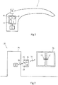
- Figure 1 shows a schematic view of an embodiment of a window handle 2 according to the present invention.
- the exemplary window handle 2 can be arranged, for example, on a window sash (not shown) of a window in order to enable a user to open the window sash, for example to bring it into a tilted position, or to close it by means of a rotational movement of the window handle 2.
- at least one actuator can also be provided in order to enable automatic opening or closing.
- the shape of the window handle shown is only one example of a large number of other shapes.
- the window handle 2 comprises a locking device 4, for example to enable the window to be opened or closed on the basis of the user action described above.
- the locking device 4 is in an operative connection with a locking device 6. This is through the connecting line in the Figure 1 indicated.
- the locking device 6 is set up to lock or release the locking device 4.
- a mechanical mechanism can be implemented.
- At least one locking bolt preferably at least two locking bolts, can be provided, which can be moved from a release position into a locking position. In the locked position, the at least one locking bolt can be in engagement with the locking device 4 in such a way that the window cannot be opened, for example by preventing a rotary movement of the window handle.
- an electronic mechanism in particular in the case of an electrically operated actuator, can also be used in order to lock or release the locking device.
- the locking device 6 has a feed-through device 8 for locking and unlocking.
- the feed-through device 8 can, for example, effect an adjustment of a locking bolt from a release position to a locking position or vice versa.
- the locking device 6 comprises a receiving device 10.
- the receiving device 10 is set up in particular to receive an electromagnetic command signal via a wireless communication channel.
- the receiving device 10 is preferably a high-frequency receiving device 10.
- the feed-through device 8 is set up to block or release the locking device 4 as a function of the command signal. If, for example, a locking command is received, the locking device 4 is locked. In the event of a release command, the locking device 4 is released.
- the locking device 6 also has a transmitting device 12.
- the transmission device 12 can in particular be a high-frequency transmission device 12.
- the transmitting device 12 is configured to to send out electromagnetic signals.
- the transmitting device 12 can be set up to transmit a status signal. After the locking device 4 has been successfully blocked, a corresponding confirmation message can be sent out in response to the command signal. If the locking device 4 cannot be locked, for example because the locking device 4 is already in the locked state or the window is open and the locking device 4 cannot be locked in this state, a corresponding message can also be sent out.
- the transmission of status signals enables the state of the window handle to be recorded and evaluated centrally and, if necessary, measures to be taken depending on the evaluation.
- the window handle 2 also has an actuating device 14.
- the actuating device 14 is designed in the form of a manually actuatable button 14.
- the actuating device 14 is in operative connection with the locking device 6, in particular with the transmitting device 12. If a user actuates the actuating device 14, for example to open the corresponding window, it can first be checked whether there is authorization for this.
- a request signal can be sent out by the transmitting device 12 in order to request a command signal, in the present case an enable signal.
- the locking device 4 can be released in the manner described and the window can be opened by a user. If no release signal is received, there is no authorization so that the locking device remains locked and the window cannot be opened.
- Figure 2 shows a schematic view of an embodiment of a system 20 according to the present invention.
- a window 36 is shown with two door leaves and two associated window handles 2.1 and 2.2.
- the window handles 2.1, 2.2 can in particular according to the Window handle 2 off Figure 1 be trained. It is understood that a plurality of windows can be provided.
- an access 34 in the form of a door 34 is shown here.
- the access 34 can be controlled by a transponder reading device 22.
- the transponder reading device 22, in particular central, comprises at least one transponder reading unit 24.
- the transponder reading unit 24 can be controlled, for example, by a processing unit 26.
- the transponder reading unit 24 is set up in particular to transmit an interrogation field 30.
- the transponder reading unit 24 can preferably transmit an interrogation field 16 and receive a response field from a transponder 40.
- the system 20 can have a plurality of transponders 40.
- a (unique) identification code can be stored in each transponder 40.
- the transponder reading device 22 can have an energy store and / or a network connection. Furthermore, the transponder reading device 22 is connected to the at least one window handle 2.1, 2.2 via a wireless communication channel 32.
- the transponder reading device 22 can monitor the access through a door 34 into a defined area.
- identification codes of authorized transponders 40 can already be stored in a memory device. If the transponder reading unit 24 receives an identification code from a transponder 40, this can be done with the stored identification codes are compared by the processing unit 26 and the input 34 released in the event of a positive comparison result. In the event of a negative result, access remains closed.
- the received identification code can then also be stored at least temporarily. For example, the identification code can remain stored until the transponder leaves the defined area. It goes without saying that appropriate markings, for example bits, can be set in the memory.
- a command signal which is in particular a release signal, can be sent to at least one window handle 2.1, 2.2, preferably all window handles 2.1, 2.2 in the defined area.
- Different authorizations can also be provided for different identification codes, for example only for a certain number of window handles 2.1, 2.2. In this case, a command signal can only be sent to this specific number of window handles 2.1, 2.2 or received by them or positively evaluated by them.
- the transponder reading device 22 can also sense the departure of a user.
- a blocking signal can be sent to the at least one window handle 2.1, 2.2 as a command signal.
- the locking device 4 of the window handle 2.1, 2.2 can then be blocked in the manner described above.
- Successful blocking can be indicated to the user by the at least one window handle 2.1, 2.2 after evaluating a response signal, such as the status signal.
- the user can also be shown on the basis of a status signal received as a response that blocking has not occurred.
- the reason for this can be displayed to the user, such as a window that is still open, so that the user can initiate appropriate measures before exiting.
- Figure 3 shows a flow diagram of an embodiment of a method according to the present invention.
- the receiving device 10 of the window handle 2, 2.1, 2.2 receives a command signal.
- an identification code of a transponder 40 located in the interrogation field of a transponder reading unit 24 can first be read out by a transponder reading device 22 and checked by a processing unit 26. Only then can a command signal be transmitted by the transponder reading device 22 and received by the receiving device 10.
- the implementation device 8 can evaluate the command signal. If the feed-through device 8 determines that it is a blocking signal, the feed-through device 8 causes the locking device 4 to be blocked in the manner described above (step 303). If the implementation device 8 determines that it is a release signal, the implementation device 8 releases the locking device 4 in the manner described above (step 304).
- a status signal in the form of a confirmation message can be sent, for example to the sender of the command signal or another entity, from a transmission device 12 of the window handle 2, 2.1, 2.2.
Landscapes
- Physics & Mathematics (AREA)
- General Physics & Mathematics (AREA)
- Lock And Its Accessories (AREA)
Claims (10)
- Système (20) comprenant au moins une poignée de fenêtre (2, 2.1, 2.2), ledit système comprenant :- au moins un dispositif de verrouillage (4) conçu pour actionner au moins une fenêtre (36), et- au moins un dispositif de fermeture (6) se trouvant en liaison fonctionnelle active avec le dispositif de verrouillage (4), ledit dispositif de fermeture étant conçu pour bloquer et/ou pour libérer le dispositif de verrouillage (4),où le dispositif de fermeture (6) présente au moins un dispositif récepteur (10) conçu pour la réception d'un signal de commande électromagnétique provenant d'un dispositif de lecture central (22) d'un transpondeur, via un canal de communication sans fil (33), et
où le dispositif de fermeture (6) présente un dispositif d'exécution (8) qui, en fonction du signal de commande ayant été reçu, est conçu pour libérer ou pour bloquer le dispositif de verrouillage (4),
où le système (20) comprend :- le dispositif de lecture central (22) - au moins au nombre de un - du transpondeur, ledit dispositif de lecture comprenant au moins une unité de lecture (24) du transpondeur, au moins une unité de traitement (26) et au moins une unité émettrice (28), et- au moins un transpondeur (40) présentant une marque d'identification,
où l'unité de lecture (24) du transpondeur est conçue pour la lecture de la marque d'identification du transpondeur (40),
où l'unité de traitement (26) est conçue pour l'analyse de la marque d'identification ayant été lue, et
où l'unité émettrice (28) est conçue pour envoyer à la poignée de fenêtre (2, 2.1, 2.2), via un canal de communication sans fil (33), un signal de commande électromagnétique, ledit signal de commande étant envoyé en fonction de l'analyse,
caractérisé- en ce que le dispositif de lecture (22) du transpondeur fait partie d'un système de contrôle d'accès à une porte. - Système (2, 2.1, 2.2) selon la revendication 1, caractérisé- en ce que le dispositif de fermeture (6) présente au moins un dispositif émetteur (12), et- en ce que le dispositif émetteur (12) est conçu pour envoyer un signal d'état électromagnétique comprenant au moins une information d'état concernant l'état de la poignée de fenêtre (2, 2.1, 2.2).
- Système (2, 2.1, 2.2) selon la revendication 2, caractérisé en ce que le dispositif émetteur (12) est conçu pour envoyer, comme information d'état, celle concernant l'état du dispositif de fermeture (6) et/ou celle concernant l'état du dispositif de verrouillage (4).
- Système (2, 2.1, 2.2) selon l'une quelconque des revendications précédentes,
caractérisé- en ce que, concernant la poignée de fenêtre, il est prévu un dispositif d'actionnement (14) se trouvant en liaison fonctionnelle active avec le dispositif émetteur (12), et- en ce que le dispositif émetteur (12) est conçu pour envoyer un signal de demande lors d'un actionnement du dispositif d'actionnement (14),
où le signal de demande est configuré pour demander un signal de commande. - Système (2, 2.1, 2.2) selon l'une quelconque des revendications précédentes,
caractérisé- en ce que, concernant la poignée de fenêtre, il est prévu au moins une alimentation en énergie, et- en ce que l'alimentation en énergie est une batterie et/ou une cellule photovoltaïque, en particulier une cellule photovoltaïque pouvant être disposée sur la fenêtre. - Système (20) selon l'une quelconque des revendications précédentes, caractérisé en ce que le dispositif de lecture (22) du transpondeur présente une unité réceptrice (28) conçue pour la réception d'un signal d'état et/ou d'un signal de demande d'une poignée de fenêtre (2, 2.1, 2.2).
- Système (20) selon la revendication 6,
caractérisé- en ce que l'unité de traitement (26) est conçue pour analyser le signal de demande ayant été reçu et pour analyser au moins une marque d'identification ayant été lue, et- en ce que l'unité émettrice (28) est conçue pour envoyer un signal de commande en fonction de l'analyse de l'unité de traitement (26). - Système (20) selon l'une quelconque des revendications précédentes,
caractérisé- en ce que le transpondeur (40) est un transpondeur RFID,
et/ou- en ce que le transpondeur (40) est passif. - Système (20) selon l'une quelconque des revendications précédentes,
caractérisé- en ce que le transpondeur (40) et l'unité de lecture (24) du transpondeur présentent des moyens de cryptage servant au cryptage de données,
et/ou- en ce que l'unité émettrice (28) et le dispositif récepteur (10) présentent des moyens de cryptage servant au cryptage de données,
et/ou- en ce que le dispositif émetteur (12) et l'unité réceptrice (28) présentent des moyens de cryptage servant au cryptage de données. - Procédé permettant le contrôle d'une poignée de fenêtre (2, 2.1, 2.2), où la poignée de fenêtre (2, 2.1, 2.2) comprend au moins un dispositif de verrouillage (4) conçu pour actionner au moins une fenêtre (36), et comprend au moins un dispositif de fermeture (6) se trouvant en liaison fonctionnelle active avec le dispositif de verrouillage (4), ledit dispositif de fermeture étant conçu pour bloquer et/ou pour libérer le dispositif de verrouillage (4), où le dispositif de fermeture (6) présente au moins un dispositif récepteur (10) conçu pour la réception d'un signal de commande électromagnétique provenant d'un dispositif de lecture central (22) d'un transpondeur, via un canal de communication sans fil (33), et où le dispositif de fermeture (6) présente un dispositif d'exécution (8) qui est conçu pour libérer ou pour bloquer le dispositif de verrouillage (4) en fonction du signal de commande ayant été reçu, ledit procédé consistant :- à recevoir, par un dispositif récepteur (10) de la poignée de fenêtre (2, 2.1, 2.2), un signal de commande électromagnétique provenant d'un dispositif de lecture central (22) d'un transpondeur, via un canal de communication sans fil (33), où le dispositif de lecture (22) du transpondeur fait partie d'un système de contrôle d'accès à une porte, et- à bloquer ou à libérer un dispositif de verrouillage (4) de la poignée de fenêtre (2, 2.1, 2.2), par un dispositif de fermeture (6), en fonction du signal de commande ayant été reçu.
Applications Claiming Priority (2)
| Application Number | Priority Date | Filing Date | Title |
|---|---|---|---|
| DE102013012862.5A DE102013012862B4 (de) | 2013-08-02 | 2013-08-02 | Elektromagnetisch sperrbarer Fenstergriff |
| PCT/EP2014/066580 WO2015014978A1 (fr) | 2013-08-02 | 2014-08-01 | Poignée de fenêtre à blocage électromagnétique |
Publications (2)
| Publication Number | Publication Date |
|---|---|
| EP3027827A1 EP3027827A1 (fr) | 2016-06-08 |
| EP3027827B1 true EP3027827B1 (fr) | 2020-09-30 |
Family
ID=51298735
Family Applications (1)
| Application Number | Title | Priority Date | Filing Date |
|---|---|---|---|
| EP14748171.7A Active EP3027827B1 (fr) | 2013-08-02 | 2014-08-01 | Poignée de fenêtre, verrouillable de façon électromagnétique |
Country Status (4)
| Country | Link |
|---|---|
| EP (1) | EP3027827B1 (fr) |
| DE (1) | DE102013012862B4 (fr) |
| ES (1) | ES2834627T3 (fr) |
| WO (1) | WO2015014978A1 (fr) |
Families Citing this family (3)
| Publication number | Priority date | Publication date | Assignee | Title |
|---|---|---|---|---|
| DE102018100578A1 (de) * | 2018-01-11 | 2019-07-11 | BSS Baumann Sicherheitssysteme GmbH | Handgriff für ein Fenster oder eine Tür und ein Alarmanlagensystem mit mehreren Handgriffen |
| EP3626917A1 (fr) * | 2018-09-24 | 2020-03-25 | Hoppe Ag | Poignée de commande pourvue de système de contrôle d'accès |
| US20220412122A1 (en) | 2020-01-21 | 2022-12-29 | Erich Matouschek | Actuating handle and device for securing against break-ins |
Citations (1)
| Publication number | Priority date | Publication date | Assignee | Title |
|---|---|---|---|---|
| WO2002029186A1 (fr) * | 2000-10-02 | 2002-04-11 | Dirak Gmbh & Co. Kg | Systeme de fermeture electronique |
Family Cites Families (7)
| Publication number | Priority date | Publication date | Assignee | Title |
|---|---|---|---|---|
| DE59610051D1 (de) * | 1995-07-19 | 2003-02-13 | Hartmut Trilk | Umschaltvorrichtung für einen tür- oder fensterbeschlag |
| DE20122749U1 (de) * | 2000-06-05 | 2007-06-06 | Esco Metallbaubeschlag-Handel Gesellschaft Mbh | Außenbeschlag für Türen oder Fenster |
| DE10163707A1 (de) | 2001-12-21 | 2003-07-03 | Hoppe Ag | Betätigungshandhabe |
| GB0200677D0 (en) * | 2002-01-14 | 2002-02-27 | Mila Hardware Ltd | Locking mechanism |
| GB2389141B (en) * | 2002-05-31 | 2005-04-13 | Giovanni Maria Laporta | A lockable handle assembly |
| DE102004013369A1 (de) | 2004-03-17 | 2005-10-06 | Dirak Dieter Ramsauer Konstruktionselemente Gmbh & Co. Kg | Elektronisches Kontroll-System |
| DE102008027001A1 (de) * | 2008-06-05 | 2009-12-10 | Trautmann, Günter, Dipl.-Ing. Dipl.-Designer | Terrassentür-bzw Fenstergriff mit eingebauter Sicherheitselektronik |
-
2013
- 2013-08-02 DE DE102013012862.5A patent/DE102013012862B4/de active Active
-
2014
- 2014-08-01 EP EP14748171.7A patent/EP3027827B1/fr active Active
- 2014-08-01 ES ES14748171T patent/ES2834627T3/es active Active
- 2014-08-01 WO PCT/EP2014/066580 patent/WO2015014978A1/fr active Application Filing
Patent Citations (1)
| Publication number | Priority date | Publication date | Assignee | Title |
|---|---|---|---|---|
| WO2002029186A1 (fr) * | 2000-10-02 | 2002-04-11 | Dirak Gmbh & Co. Kg | Systeme de fermeture electronique |
Also Published As
| Publication number | Publication date |
|---|---|
| DE102013012862A1 (de) | 2015-02-05 |
| DE102013012862B4 (de) | 2022-10-06 |
| ES2834627T3 (es) | 2021-06-18 |
| EP3027827A1 (fr) | 2016-06-08 |
| WO2015014978A1 (fr) | 2015-02-05 |
Similar Documents
| Publication | Publication Date | Title |
|---|---|---|
| EP2842110B9 (fr) | Système de verrouillage électronique et procédé de validation d'une autorisation d'accès | |
| DE19738938B4 (de) | Schloß | |
| EP3058553B1 (fr) | Procédé d'exploitation d'un système de verrouillage, système de verrouillage et tube de sécurité | |
| DE112016004841T5 (de) | Elektronisches Schloss und elektronisches Verriegelungssystem für Möbel, Schränke oder Schliessfächer | |
| DE10028176A1 (de) | Selbstverriegelndes Schloß und mit diesem ausgestattetes Schließsystem | |
| EP0709534B1 (fr) | Serrure activée par un porteur d'identité | |
| DE102005034618B4 (de) | Elektronische Schließeinrichtung und Schließverfahren | |
| EP3027827B1 (fr) | Poignée de fenêtre, verrouillable de façon électromagnétique | |
| DE102004013369A1 (de) | Elektronisches Kontroll-System | |
| DE10056119A1 (de) | Elektronisch codierbares Schloss-System | |
| DE19527801C2 (de) | Schließsystem | |
| WO2011100939A1 (fr) | Système de verrouillage de porte | |
| EP2457220A1 (fr) | Système de contrôle d' accès numérique | |
| EP1338735B1 (fr) | Système, installation et procédé de contrôle d'accès | |
| WO2017157831A1 (fr) | Système de déverrouillage d'une serrrure d'un espace à verrrouiller | |
| EP4050188A1 (fr) | Système de porte pour au moins une porte | |
| EP3131068B1 (fr) | Verrou de porte d'armoire en communication sans fil avec une unite centrale | |
| DE102021125075B3 (de) | Funkschlüsselsystem zum berührungsfreien Öffnen eines elektronischen Schlosses | |
| CH700937B1 (de) | Betätigungseinrichtung für Schliessfächer. | |
| DE102004056987A1 (de) | Schließvorrichtung und Schließanlage, umfassend wenigstens eine Schließvorrichtung | |
| EP3905208B1 (fr) | Mise à niveau d'une porte électromécanique | |
| EP3133559A2 (fr) | Systeme de fermeture de batiment | |
| EP2851873B1 (fr) | Clé RFID, notamment unité de transpondeur RFID, dispositif et procédé de programmation et dispositif et procédé de verrouillage présentant un verrou RFID et système le composant | |
| DE202004004273U1 (de) | Elektronisches Kontroll-System | |
| DE202005022089U1 (de) | ELektronische Schließeinrichtung |
Legal Events
| Date | Code | Title | Description |
|---|---|---|---|
| PUAI | Public reference made under article 153(3) epc to a published international application that has entered the european phase |
Free format text: ORIGINAL CODE: 0009012 |
|
| 17P | Request for examination filed |
Effective date: 20160120 |
|
| AK | Designated contracting states |
Kind code of ref document: A1 Designated state(s): AL AT BE BG CH CY CZ DE DK EE ES FI FR GB GR HR HU IE IS IT LI LT LU LV MC MK MT NL NO PL PT RO RS SE SI SK SM TR |
|
| AX | Request for extension of the european patent |
Extension state: BA ME |
|
| DAX | Request for extension of the european patent (deleted) | ||
| RAP1 | Party data changed (applicant data changed or rights of an application transferred) |
Owner name: TERATRON GMBH |
|
| STAA | Information on the status of an ep patent application or granted ep patent |
Free format text: STATUS: EXAMINATION IS IN PROGRESS |
|
| 17Q | First examination report despatched |
Effective date: 20190730 |
|
| GRAP | Despatch of communication of intention to grant a patent |
Free format text: ORIGINAL CODE: EPIDOSNIGR1 |
|
| STAA | Information on the status of an ep patent application or granted ep patent |
Free format text: STATUS: GRANT OF PATENT IS INTENDED |
|
| INTG | Intention to grant announced |
Effective date: 20200317 |
|
| GRAS | Grant fee paid |
Free format text: ORIGINAL CODE: EPIDOSNIGR3 |
|
| GRAJ | Information related to disapproval of communication of intention to grant by the applicant or resumption of examination proceedings by the epo deleted |
Free format text: ORIGINAL CODE: EPIDOSDIGR1 |
|
| GRAL | Information related to payment of fee for publishing/printing deleted |
Free format text: ORIGINAL CODE: EPIDOSDIGR3 |
|
| STAA | Information on the status of an ep patent application or granted ep patent |
Free format text: STATUS: EXAMINATION IS IN PROGRESS |
|
| GRAR | Information related to intention to grant a patent recorded |
Free format text: ORIGINAL CODE: EPIDOSNIGR71 |
|
| STAA | Information on the status of an ep patent application or granted ep patent |
Free format text: STATUS: GRANT OF PATENT IS INTENDED |
|
| GRAA | (expected) grant |
Free format text: ORIGINAL CODE: 0009210 |
|
| STAA | Information on the status of an ep patent application or granted ep patent |
Free format text: STATUS: THE PATENT HAS BEEN GRANTED |
|
| INTC | Intention to grant announced (deleted) | ||
| AK | Designated contracting states |
Kind code of ref document: B1 Designated state(s): AL AT BE BG CH CY CZ DE DK EE ES FI FR GB GR HR HU IE IS IT LI LT LU LV MC MK MT NL NO PL PT RO RS SE SI SK SM TR |
|
| INTG | Intention to grant announced |
Effective date: 20200821 |
|
| REG | Reference to a national code |
Ref country code: GB Ref legal event code: FG4D Free format text: NOT ENGLISH Ref country code: CH Ref legal event code: EP |
|
| REG | Reference to a national code |
Ref country code: AT Ref legal event code: REF Ref document number: 1318946 Country of ref document: AT Kind code of ref document: T Effective date: 20201015 |
|
| REG | Reference to a national code |
Ref country code: DE Ref legal event code: R096 Ref document number: 502014014819 Country of ref document: DE |
|
| REG | Reference to a national code |
Ref country code: IE Ref legal event code: FG4D Free format text: LANGUAGE OF EP DOCUMENT: GERMAN |
|
| REG | Reference to a national code |
Ref country code: CH Ref legal event code: NV Representative=s name: SCHMAUDER AND PARTNER AG PATENT- UND MARKENANW, CH |
|
| REG | Reference to a national code |
Ref country code: NL Ref legal event code: FP |
|
| PG25 | Lapsed in a contracting state [announced via postgrant information from national office to epo] |
Ref country code: BG Free format text: LAPSE BECAUSE OF FAILURE TO SUBMIT A TRANSLATION OF THE DESCRIPTION OR TO PAY THE FEE WITHIN THE PRESCRIBED TIME-LIMIT Effective date: 20201230 Ref country code: NO Free format text: LAPSE BECAUSE OF FAILURE TO SUBMIT A TRANSLATION OF THE DESCRIPTION OR TO PAY THE FEE WITHIN THE PRESCRIBED TIME-LIMIT Effective date: 20201230 Ref country code: GR Free format text: LAPSE BECAUSE OF FAILURE TO SUBMIT A TRANSLATION OF THE DESCRIPTION OR TO PAY THE FEE WITHIN THE PRESCRIBED TIME-LIMIT Effective date: 20201231 Ref country code: FI Free format text: LAPSE BECAUSE OF FAILURE TO SUBMIT A TRANSLATION OF THE DESCRIPTION OR TO PAY THE FEE WITHIN THE PRESCRIBED TIME-LIMIT Effective date: 20200930 Ref country code: HR Free format text: LAPSE BECAUSE OF FAILURE TO SUBMIT A TRANSLATION OF THE DESCRIPTION OR TO PAY THE FEE WITHIN THE PRESCRIBED TIME-LIMIT Effective date: 20200930 Ref country code: SE Free format text: LAPSE BECAUSE OF FAILURE TO SUBMIT A TRANSLATION OF THE DESCRIPTION OR TO PAY THE FEE WITHIN THE PRESCRIBED TIME-LIMIT Effective date: 20200930 |
|
| PG25 | Lapsed in a contracting state [announced via postgrant information from national office to epo] |
Ref country code: LV Free format text: LAPSE BECAUSE OF FAILURE TO SUBMIT A TRANSLATION OF THE DESCRIPTION OR TO PAY THE FEE WITHIN THE PRESCRIBED TIME-LIMIT Effective date: 20200930 Ref country code: RS Free format text: LAPSE BECAUSE OF FAILURE TO SUBMIT A TRANSLATION OF THE DESCRIPTION OR TO PAY THE FEE WITHIN THE PRESCRIBED TIME-LIMIT Effective date: 20200930 |
|
| REG | Reference to a national code |
Ref country code: LT Ref legal event code: MG4D |
|
| PG25 | Lapsed in a contracting state [announced via postgrant information from national office to epo] |
Ref country code: SM Free format text: LAPSE BECAUSE OF FAILURE TO SUBMIT A TRANSLATION OF THE DESCRIPTION OR TO PAY THE FEE WITHIN THE PRESCRIBED TIME-LIMIT Effective date: 20200930 Ref country code: RO Free format text: LAPSE BECAUSE OF FAILURE TO SUBMIT A TRANSLATION OF THE DESCRIPTION OR TO PAY THE FEE WITHIN THE PRESCRIBED TIME-LIMIT Effective date: 20200930 Ref country code: LT Free format text: LAPSE BECAUSE OF FAILURE TO SUBMIT A TRANSLATION OF THE DESCRIPTION OR TO PAY THE FEE WITHIN THE PRESCRIBED TIME-LIMIT Effective date: 20200930 Ref country code: PT Free format text: LAPSE BECAUSE OF FAILURE TO SUBMIT A TRANSLATION OF THE DESCRIPTION OR TO PAY THE FEE WITHIN THE PRESCRIBED TIME-LIMIT Effective date: 20210201 Ref country code: CZ Free format text: LAPSE BECAUSE OF FAILURE TO SUBMIT A TRANSLATION OF THE DESCRIPTION OR TO PAY THE FEE WITHIN THE PRESCRIBED TIME-LIMIT Effective date: 20200930 Ref country code: EE Free format text: LAPSE BECAUSE OF FAILURE TO SUBMIT A TRANSLATION OF THE DESCRIPTION OR TO PAY THE FEE WITHIN THE PRESCRIBED TIME-LIMIT Effective date: 20200930 |
|
| PG25 | Lapsed in a contracting state [announced via postgrant information from national office to epo] |
Ref country code: IS Free format text: LAPSE BECAUSE OF FAILURE TO SUBMIT A TRANSLATION OF THE DESCRIPTION OR TO PAY THE FEE WITHIN THE PRESCRIBED TIME-LIMIT Effective date: 20210130 Ref country code: PL Free format text: LAPSE BECAUSE OF FAILURE TO SUBMIT A TRANSLATION OF THE DESCRIPTION OR TO PAY THE FEE WITHIN THE PRESCRIBED TIME-LIMIT Effective date: 20200930 Ref country code: AL Free format text: LAPSE BECAUSE OF FAILURE TO SUBMIT A TRANSLATION OF THE DESCRIPTION OR TO PAY THE FEE WITHIN THE PRESCRIBED TIME-LIMIT Effective date: 20200930 |
|
| REG | Reference to a national code |
Ref country code: ES Ref legal event code: FG2A Ref document number: 2834627 Country of ref document: ES Kind code of ref document: T3 Effective date: 20210618 |
|
| PG25 | Lapsed in a contracting state [announced via postgrant information from national office to epo] |
Ref country code: SK Free format text: LAPSE BECAUSE OF FAILURE TO SUBMIT A TRANSLATION OF THE DESCRIPTION OR TO PAY THE FEE WITHIN THE PRESCRIBED TIME-LIMIT Effective date: 20200930 |
|
| REG | Reference to a national code |
Ref country code: DE Ref legal event code: R097 Ref document number: 502014014819 Country of ref document: DE |
|
| PLBE | No opposition filed within time limit |
Free format text: ORIGINAL CODE: 0009261 |
|
| STAA | Information on the status of an ep patent application or granted ep patent |
Free format text: STATUS: NO OPPOSITION FILED WITHIN TIME LIMIT |
|
| PG25 | Lapsed in a contracting state [announced via postgrant information from national office to epo] |
Ref country code: DK Free format text: LAPSE BECAUSE OF FAILURE TO SUBMIT A TRANSLATION OF THE DESCRIPTION OR TO PAY THE FEE WITHIN THE PRESCRIBED TIME-LIMIT Effective date: 20200930 |
|
| 26N | No opposition filed |
Effective date: 20210701 |
|
| PG25 | Lapsed in a contracting state [announced via postgrant information from national office to epo] |
Ref country code: SI Free format text: LAPSE BECAUSE OF FAILURE TO SUBMIT A TRANSLATION OF THE DESCRIPTION OR TO PAY THE FEE WITHIN THE PRESCRIBED TIME-LIMIT Effective date: 20200930 |
|
| PG25 | Lapsed in a contracting state [announced via postgrant information from national office to epo] |
Ref country code: MC Free format text: LAPSE BECAUSE OF FAILURE TO SUBMIT A TRANSLATION OF THE DESCRIPTION OR TO PAY THE FEE WITHIN THE PRESCRIBED TIME-LIMIT Effective date: 20200930 |
|
| GBPC | Gb: european patent ceased through non-payment of renewal fee |
Effective date: 20210801 |
|
| PG25 | Lapsed in a contracting state [announced via postgrant information from national office to epo] |
Ref country code: IS Free format text: LAPSE BECAUSE OF FAILURE TO SUBMIT A TRANSLATION OF THE DESCRIPTION OR TO PAY THE FEE WITHIN THE PRESCRIBED TIME-LIMIT Effective date: 20210130 |
|
| PG25 | Lapsed in a contracting state [announced via postgrant information from national office to epo] |
Ref country code: IE Free format text: LAPSE BECAUSE OF NON-PAYMENT OF DUE FEES Effective date: 20210801 Ref country code: GB Free format text: LAPSE BECAUSE OF NON-PAYMENT OF DUE FEES Effective date: 20210801 |
|
| PG25 | Lapsed in a contracting state [announced via postgrant information from national office to epo] |
Ref country code: HU Free format text: LAPSE BECAUSE OF FAILURE TO SUBMIT A TRANSLATION OF THE DESCRIPTION OR TO PAY THE FEE WITHIN THE PRESCRIBED TIME-LIMIT; INVALID AB INITIO Effective date: 20140801 |
|
| PG25 | Lapsed in a contracting state [announced via postgrant information from national office to epo] |
Ref country code: CY Free format text: LAPSE BECAUSE OF FAILURE TO SUBMIT A TRANSLATION OF THE DESCRIPTION OR TO PAY THE FEE WITHIN THE PRESCRIBED TIME-LIMIT Effective date: 20200930 |
|
| PGFP | Annual fee paid to national office [announced via postgrant information from national office to epo] |
Ref country code: NL Payment date: 20230823 Year of fee payment: 10 Ref country code: LU Payment date: 20230823 Year of fee payment: 10 |
|
| PGFP | Annual fee paid to national office [announced via postgrant information from national office to epo] |
Ref country code: IT Payment date: 20230823 Year of fee payment: 10 Ref country code: ES Payment date: 20230925 Year of fee payment: 10 Ref country code: CH Payment date: 20230902 Year of fee payment: 10 Ref country code: AT Payment date: 20230825 Year of fee payment: 10 |
|
| PGFP | Annual fee paid to national office [announced via postgrant information from national office to epo] |
Ref country code: FR Payment date: 20230822 Year of fee payment: 10 Ref country code: DE Payment date: 20230823 Year of fee payment: 10 Ref country code: BE Payment date: 20230823 Year of fee payment: 10 |
|
| PG25 | Lapsed in a contracting state [announced via postgrant information from national office to epo] |
Ref country code: MK Free format text: LAPSE BECAUSE OF FAILURE TO SUBMIT A TRANSLATION OF THE DESCRIPTION OR TO PAY THE FEE WITHIN THE PRESCRIBED TIME-LIMIT Effective date: 20200930 |