EP1800010B1 - Seitenkanalverdichter sowie gehäuseschalen und laufrad hierfür - Google Patents
Seitenkanalverdichter sowie gehäuseschalen und laufrad hierfür Download PDFInfo
- Publication number
- EP1800010B1 EP1800010B1 EP05795972A EP05795972A EP1800010B1 EP 1800010 B1 EP1800010 B1 EP 1800010B1 EP 05795972 A EP05795972 A EP 05795972A EP 05795972 A EP05795972 A EP 05795972A EP 1800010 B1 EP1800010 B1 EP 1800010B1
- Authority
- EP
- European Patent Office
- Prior art keywords
- rotor
- housing shell
- side channel
- channel compressor
- compressor according
- Prior art date
- Legal status (The legal status is an assumption and is not a legal conclusion. Google has not performed a legal analysis and makes no representation as to the accuracy of the status listed.)
- Expired - Lifetime
Links
Images


Classifications
-
- F—MECHANICAL ENGINEERING; LIGHTING; HEATING; WEAPONS; BLASTING
- F04—POSITIVE - DISPLACEMENT MACHINES FOR LIQUIDS; PUMPS FOR LIQUIDS OR ELASTIC FLUIDS
- F04D—NON-POSITIVE-DISPLACEMENT PUMPS
- F04D23/00—Other rotary non-positive-displacement pumps
- F04D23/008—Regenerative pumps
-
- F—MECHANICAL ENGINEERING; LIGHTING; HEATING; WEAPONS; BLASTING
- F04—POSITIVE - DISPLACEMENT MACHINES FOR LIQUIDS; PUMPS FOR LIQUIDS OR ELASTIC FLUIDS
- F04D—NON-POSITIVE-DISPLACEMENT PUMPS
- F04D29/00—Details, component parts, or accessories
- F04D29/08—Sealings
- F04D29/083—Sealings especially adapted for elastic fluid pumps
-
- F—MECHANICAL ENGINEERING; LIGHTING; HEATING; WEAPONS; BLASTING
- F04—POSITIVE - DISPLACEMENT MACHINES FOR LIQUIDS; PUMPS FOR LIQUIDS OR ELASTIC FLUIDS
- F04D—NON-POSITIVE-DISPLACEMENT PUMPS
- F04D29/00—Details, component parts, or accessories
- F04D29/60—Mounting; Assembling; Disassembling
- F04D29/62—Mounting; Assembling; Disassembling of radial or helico-centrifugal pumps
- F04D29/622—Adjusting the clearances between rotary and stationary parts
Definitions
- a housing and an impeller include a channel. On the impeller blades are mounted, which protrude into the channel, but not completely fill. As seen in the direction of rotation of the impeller, an inlet to the duct is provided in front of an outlet from the duct.
- the channel comprises two areas, one traversed by the blades of the impeller, and the side channel which is not traversed by the blades. Between inlet and outlet a breaker is provided which closes the side channel.
- the effective length of the breaker must be slightly longer than a blade clearance.
- the interface between the side channel and the remainder of the channel is often a plane perpendicular to the axis of rotation of the impeller or a conical surface whose axis coincides with the axis of rotation of the impeller.
- the inlet Through the inlet enters a fluid, often a gas, in particular air in the channel. Part of the fluid molecules is entrained by a blade in the tangential direction. Due to the centrifugal force, the considered fluid molecules are also accelerated radially outwards and thus flow out of the blade into the side channel. There they are deflected in the direction of the impeller and learn through the impeller further acceleration. The fluid molecules are thus conveyed on a toroidally curved helical path from the inlet to the outlet, wherein the pressure in the fluid increases.
- the breaker is intended to minimize the amount of fluid being drawn from the outlet to the inlet.
- the US 6,086,325 discloses a side channel compressor with two channels formed on opposite sides of an impeller. Each channel is formed half of the impeller and the other half of each a different housing part, these two housing parts are screwed.
- the US 4,483,656 also discloses a side channel compressor with only one channel.
- the channel is formed again about half of a single housing part and about the other half of an impeller.
- On the other side of the impeller is a cover which is fixed to the housing part.
- a cost saving is achieved in particular by a structure in which the housing can consist of one piece, namely the housing shell, which houses the side channel.
- a relative to the housing shell sealed lid which can be designed plan, reduces the leakage through the outer annular sealing point, protects the impeller from contact and the contact ends in front of the impeller
- a cup-spring-nut system allows the adjustment of the two gap dimensions of the two annular sealing points, so that it is possible to work with higher tolerances during production and the gap losses nevertheless remain within the framework. This is especially true in the production of small ones Side channel compressors important, which must deliver a lower gas flow than the commercial side channel blower and of which one therefore expects a smaller design.
- the cooling of the side channel compressor can be improved in a simple manner by attaching a fan at the end of the motor shaft facing away from the impeller.
- a honeycomb structure on the housing shell of the side channel compressor improves the rigidity of the shell and may additionally act as a cooling plate when the side channel compressor is mounted with the honeycomb structure upwards.
- the honeycomb structure for a given stiffness lowers the weight of the housing shell and the material consumption for the manufacture of the housing shell.
- Fig. 1 shows a section through a side channel compressor 1 according to the invention.
- the channel is located between the impeller 3 and housing shell 2 in the region Y, which in Fig. 3 is shown enlarged.
- the housing of a motor 4 may be attached directly to the housing shell 2.
- the impeller 3 is attached via a diaphragm spring-nut system in the region Z to the motor shaft.
- the area Z is in Fig. 4 shown enlarged.
- a cover 5 is fastened with screws 6 to the housing shell 2 and protects the rotating with more than 10,000 rev / min impeller 3 against contact.
- Cover 5 may be tight relative to the housing shell 2. This reduces the permeability of the outer sealing point 32.
- a pressure is formed, which lies between the pressure at the inlet and the pressure at the outlet. If one assumes that the pressure at the inlet corresponds approximately to the ambient pressure, then cover 5 reduces the pressure difference at sealing point 32 shortly before the outlet, which reduces the leakage current accordingly.
- housing shell 2 has an edge 10.
- Housing shell 2 is with the channel, the sealing points, the cooling fins and the inlet and outlet anyway a complicated component.
- housing shell 2 may be equipped with cooling fins 7.
- a fan 9 may be attached to the side facing away from the impeller 3 of the motor shaft.
- One Heilbachsrohr 8 ensures that the promoted by fan 9 air sweeps as completely as possible by cooling fins 7.
- the Heilstoffsrohr 8 can be firmly clamped in notches 14 in the cooling fins 7, which allows easy assembly and disassembly of the air duct 8.
- the Heilgungsrohr 8 can also be stuck firmly.
- axial fan 9 shown can also be used a radial fan.
- the vanes are typically arranged between two disks, one disk being driven and the other disk having a central hole through which air is drawn.
- the outer radius of the driven disc is smaller than the inner radius of the ventilation tube 8 by the distance between the two discs.
- the outer radius of the perforated disc is insubstantially smaller than the inner diameter of the ventilation tube 8 and the ventilation tube 8 is at least long enough to pierce it Slice comes up and a narrow gap between the perforated disc and vent tube 8 remains.
- the radius of the perforated disc is not critical, but can be chosen so large that the area of the hole in the perforated disc is about as large as the clear surface between the driven disc and vent 8th
- Fig. 2 shows a perspective view of the in FIG. 1 Arrows indicate that cooling air is sucked in by fan 9, passed through ventilation pipe 8 to the cooling fins 7 and then flows through the cooling fins 7 approximately radially into the environment to the outside. Additionally shows Fig. 2 an inlet 11 and an outlet 12 for the air conveyed by impeller 3 and fastening loops 13.
- Fig. 3 shows the area Y enlarged.
- impeller 3 and housing shell 2 are particularly close.
- a dead volume chamber seal 33 is provided by way of example. This has the goal to swirl the airflow flowing through the sealing gap between the impeller 3 and the housing shell 2 as much as possible and thus to make the flow resistance of the sealing gap as large as possible. If possible, there should be no current threads entering the next choke point.
- the air in the channel turns clockwise.
- the sealing gap runs at sealing point 31 from the channel to the bottom left before the sealing gap widens to Totvolumensch 33.
- the orientation of the seal is chosen so that the highest elevation is directed with respect to the direction of movement of the air molecules.
- the Totvolumenhunt has an approximately circular cross-section, with a smaller circle segment of impeller 3 and a larger circle segment of housing shell 2 is cut. According to the course of the sealing gap, the leakage occurs from the top right in the Totvolumenhunt, flows through this and meets on the opposite side of the housing shell 2. This and the movement of the impeller 3 relative to the housing shell 2, the air is swirled, which the sealing effect of Totvolumenhunt promotes.
- the Totvolumenschabdichtung 33 is shown only by way of example at the inner sealing points 31. It may alternatively or additionally be provided at the outer sealing points 32 substantially point-symmetrical to the center of the approximately circular channel cross-section.
- Fig. 4 shows a first embodiment for the area Z increases. It recognizes impeller mount 41, which is glued to the motor shaft 40, for example, or fixed by means of a press fit. Disc spring 42 is clamped between a flange of the impeller mount 41 and impeller 3. On its other side impeller 3 is pressed by washer 44 and nut 43 against disc spring 42. By tightening or loosening of nut 43 with respect to impeller seat 41 disc spring 42 is pressed more or less together and the sealing gaps between impeller 3 and housing shell 2 reduced bew. Enlarged. The leadership of impeller 3 is mainly determined by the quality of the fit between the impeller 3 and impeller mount 41. Impeller mount 41 and impeller 3 can positively engage with each other. The positive connection can be generated by noses or flats
- Fig. 5 shows a second embodiment for the area Z.
- the washer is missing.
- a lock nut 46 is provided to unintentionally release nut 43 during operation prevent.
- the impeller 45 has a recess for nut 43 so that impeller 45 can serve as a wrench during assembly.
- This recess can be hexagonal to optimally transfer torque to nut 43.
- the recess may also be rectangular, wherein the short side of the rectangle corresponds to the nut width of the nut and wherein the effect of the recess is then more comparable to a fork wrench.
- the positive connection between nut 43 and impeller 45, together with lock nut 46 ensures reliable torque transmission from motor shaft 40 to impeller 41 via impeller mount 41, thereby preventing slippage.
- a fit between the impeller mount 41 and impeller 45 is provided.
- Fig. 6 shows the third embodiment for the area Z.
- thread 49 may extend over the entire central bore in impeller 48.
- the end facing away from the impeller 3 of motor shaft 40 which protrudes beyond the motor housing or impeller 9, square, hexagonal, at least not be round.
- Fig. 7 shows a section through a further embodiment of a side channel compressor according to the invention.
- side channel blower fan 9 and Heilgebersrohr 8 are not mounted.
- cooling fins 7 notches 14 so that a ventilation tube 8 can be easily infected.
- the motor shaft projects beyond the motor housing down, so that a fan 9 can be plugged.
- the interesting area X is in Fig. 8 shown enlarged.
- Fig. 8 shows the attachment of the motor 4 by means of a swash plate 61 on the housing shell 2.
- impeller 3 is fixed by means of a Laufradability 64, a washer 65 and a nut 66 to the motor shaft 60.
- a plate spring is unnecessary, since the gap dimensions can be adjusted via adjusting screws 63, but can also be mounted.
- the motor housing is directly on swash plate 61, for example by means of Adhesive or screws attached.
- Springs 62 press swash plate 61 against adjusting screws 63 and thus suppress play.
- Swash plate 61, springs 62 and adjusting screws 63 may be referred to as a wobble device.
- swash plate 61 may be missing.
- the heads of the adjusting screws 63 rest in stepped bores in the housing shell 2.
- the motor housing has threaded holes for the adjusting screws.
- Springs 62 push the motor housing and housing shell 2 apart against the adjusting screws 63 to provide tension and suppress play.
- impeller 3 has through holes above the adjusting screws, through which the heads of the adjusting screws are accessible.
- Fig. 9 shows a perspective view of the in Fig. 7 shown side channel compressor.
- the honeycomb structure 71 is shown, which gives the housing shell additional strength and leads to a material saving for a given strength. Is honeycomb 71 upwardly aligned, as in Fig. 9 the case is so that heated air can rise, the honeycomb structure supports the effect of the cooling fins 7.
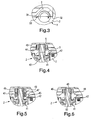
- Fig. 10 a further embodiment of a side channel compressor is shown, in which the housing shell 81 is made of an extruded profile.
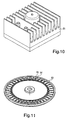
- Fig. 11 shows an impeller 93 with functional blades 94 and intermediate blades 95.
- the functional blades 94 range from a sealing gap up to the breaker zoom.
- the intermediate blades 95 have a considerable distance to the breaker when installed. In one embodiment, its height is 2/3 of the height of the functional blades. The intermediate blades serve to reduce noise.
- the outlet-side edge of the breaker is arranged obliquely opposite to the blades of the impeller. This also serves to reduce noise. It is particularly advantageous if the angle between this edge and the blades of the impeller is selected so that this edge the space between the leading edges of two adjacent blades sweeps.
- the outlet side boundary of the breaker may also be composed of several edges. In the case of two edges this boundary has an arrow shape, in the case of more edges this border is saw-shaped with a multitude of saw teeth. The particularly advantageous length of a blade distance of the edges in the tangential direction is maintained.
- the inlet-side edge of the breaker may be oblique just like the outlet-side edge and composed of several edges. Again, the preferred length in the tangential direction is a blade distance.
- the side channel blower according to the invention is used primarily for the delivery of air, other gases or even fluids in general can be promoted. Due to the low compressibility of liquids, one does not have the problem here that the liquid dragged across the breaker expands in the area of the inlet.
Landscapes
- Engineering & Computer Science (AREA)
- Mechanical Engineering (AREA)
- General Engineering & Computer Science (AREA)
- Structures Of Non-Positive Displacement Pumps (AREA)
- Compressor (AREA)
- Applications Or Details Of Rotary Compressors (AREA)
Applications Claiming Priority (2)
| Application Number | Priority Date | Filing Date | Title |
|---|---|---|---|
| DE102004049613A DE102004049613A1 (de) | 2004-10-12 | 2004-10-12 | Seitenkanalverdichter sowie Gehäuseschalen und Laufrad hierfür |
| PCT/DE2005/001779 WO2006039894A2 (de) | 2004-10-12 | 2005-10-05 | Seitenkanalverdichter sowie gehäuseschalen und laufrad hierfür |
Publications (2)
| Publication Number | Publication Date |
|---|---|
| EP1800010A2 EP1800010A2 (de) | 2007-06-27 |
| EP1800010B1 true EP1800010B1 (de) | 2009-07-01 |
Family
ID=35457214
Family Applications (1)
| Application Number | Title | Priority Date | Filing Date |
|---|---|---|---|
| EP05795972A Expired - Lifetime EP1800010B1 (de) | 2004-10-12 | 2005-10-05 | Seitenkanalverdichter sowie gehäuseschalen und laufrad hierfür |
Country Status (8)
| Country | Link |
|---|---|
| US (1) | US7591632B2 (enExample) |
| EP (1) | EP1800010B1 (enExample) |
| JP (1) | JP5042840B2 (enExample) |
| CN (1) | CN101076670B (enExample) |
| AT (1) | ATE435373T1 (enExample) |
| DE (2) | DE102004049613A1 (enExample) |
| ES (1) | ES2330768T3 (enExample) |
| WO (1) | WO2006039894A2 (enExample) |
Families Citing this family (12)
| Publication number | Priority date | Publication date | Assignee | Title |
|---|---|---|---|---|
| US8215928B2 (en) * | 2007-10-02 | 2012-07-10 | R&D Dynamics Corporation | Foil gas bearing supported high temperature centrifugal blower and method for cooling thereof |
| US8267640B1 (en) * | 2008-05-27 | 2012-09-18 | Crane Pumps & Systems, Inc | Turbine pump with floating raceway |
| US9951784B2 (en) | 2010-07-27 | 2018-04-24 | R&D Dynamics Corporation | Mechanically-coupled turbomachinery configurations and cooling methods for hermetically-sealed high-temperature operation |
| WO2012094287A2 (en) * | 2011-01-05 | 2012-07-12 | Borgwarner Inc. | Impeller design for fluid pump assembly and method of making |
| US9476428B2 (en) | 2011-06-01 | 2016-10-25 | R & D Dynamics Corporation | Ultra high pressure turbomachine for waste heat recovery |
| DE102012023347B3 (de) * | 2012-11-29 | 2014-01-30 | Tni Medical Ag | Kleiner, geräuscharmer Seitenkanalverdichter, insbesondere für Geräte in der Beatmungstherapie |
| GB2532104B (en) * | 2013-06-13 | 2016-10-05 | Dyson Technology Ltd | Controlling the power consumption of a brushless motor |
| DE102013226563B4 (de) * | 2013-12-19 | 2017-03-09 | Eberspächer Climate Control Systems GmbH & Co. KG | Gebläsegehäuse, insbesondere für ein Seitenkanalgebläse |
| US10007238B1 (en) | 2015-01-22 | 2018-06-26 | John C. Taube | Oxygen mixing and delivery |
| DE102018219995A1 (de) | 2018-11-22 | 2020-05-28 | Robert Bosch Gmbh | Seitenkanalverdichter für ein Brennstoffzellensystem zur Förderung und/oder Verdichtung von einem gasförmigen Medium |
| DE102018220007A1 (de) * | 2018-11-22 | 2020-05-28 | Robert Bosch Gmbh | Seitenkanalverdichter für ein Brennstoffzellensystem zur Förderung und/oder Verdichtung von einem gasförmigen Medium |
| CN114876792B (zh) * | 2022-06-02 | 2023-06-16 | 重庆建设车用空调器有限责任公司 | 一种电动涡旋压缩机的壳体结构 |
Family Cites Families (19)
| Publication number | Priority date | Publication date | Assignee | Title |
|---|---|---|---|---|
| DE835832C (de) * | 1949-04-28 | 1952-04-03 | Siemens Ag | Kreiselmaschine |
| US3356033A (en) * | 1965-10-22 | 1967-12-05 | Ford Motor Co | Centrifugal fluid pump |
| JPS4945413A (enExample) * | 1972-09-06 | 1974-04-30 | ||
| JPS54108916A (en) * | 1978-02-15 | 1979-08-27 | Hitachi Ltd | Eddy blower |
| JPS58106195A (ja) * | 1981-12-18 | 1983-06-24 | Hitachi Ltd | 渦流送風機 |
| JPS58174064U (ja) * | 1982-05-14 | 1983-11-21 | 林刃物株式会社 | はさみ類の枢着機構 |
| JPS595792U (ja) * | 1982-06-30 | 1984-01-14 | 三菱電機株式会社 | うず流れ形ポンプ |
| JPS62128188U (enExample) * | 1986-02-07 | 1987-08-13 | ||
| JPS6310286U (enExample) * | 1986-07-08 | 1988-01-23 | ||
| KR910012551A (ko) * | 1989-09-14 | 1991-08-08 | 이다가끼 유끼오 | 송풍기 |
| JP2865849B2 (ja) * | 1990-10-19 | 1999-03-08 | 株式会社日立製作所 | 渦流ポンプ |
| JP2917563B2 (ja) * | 1991-04-15 | 1999-07-12 | 株式会社デンソー | 渦流式ポンプ |
| JP3035196B2 (ja) * | 1995-09-06 | 2000-04-17 | 株式会社椿本エマソン | 過負荷保護装置付中空軸減速機 |
| CN1196777A (zh) * | 1995-09-15 | 1998-10-21 | 西门子公司 | 由两个半壳体组成的侧通道压缩机的壳体 |
| DE19649529A1 (de) | 1996-11-29 | 1998-06-04 | Duerr Dental Gmbh Co Kg | Seitenkanalmaschine |
| DE19847522C1 (de) * | 1998-10-15 | 1999-11-04 | Webasto Thermosysteme Gmbh | Ringkanalgebläse |
| JP4048311B2 (ja) * | 2000-03-17 | 2008-02-20 | 株式会社豊田自動織機 | 電動圧縮機 |
| DE20214104U1 (de) | 2002-09-12 | 2003-04-03 | nash_elmo Industries GmbH, 90461 Nürnberg | Seitenkanalverdichter |
| DE20309258U1 (de) * | 2003-06-16 | 2003-12-11 | Liu, Wen-Hui | Wirbelgebläse |
-
2004
- 2004-10-12 DE DE102004049613A patent/DE102004049613A1/de not_active Withdrawn
-
2005
- 2005-10-05 WO PCT/DE2005/001779 patent/WO2006039894A2/de not_active Ceased
- 2005-10-05 DE DE502005007633T patent/DE502005007633D1/de not_active Expired - Lifetime
- 2005-10-05 ES ES05795972T patent/ES2330768T3/es not_active Expired - Lifetime
- 2005-10-05 CN CN2005800426094A patent/CN101076670B/zh not_active Expired - Lifetime
- 2005-10-05 EP EP05795972A patent/EP1800010B1/de not_active Expired - Lifetime
- 2005-10-05 AT AT05795972T patent/ATE435373T1/de active
- 2005-10-05 JP JP2007535010A patent/JP5042840B2/ja not_active Expired - Lifetime
-
2007
- 2007-04-11 US US11/786,451 patent/US7591632B2/en active Active
Also Published As
| Publication number | Publication date |
|---|---|
| JP5042840B2 (ja) | 2012-10-03 |
| CN101076670B (zh) | 2011-07-06 |
| DE102004049613A1 (de) | 2006-04-13 |
| US7591632B2 (en) | 2009-09-22 |
| DE502005007633D1 (de) | 2009-08-13 |
| WO2006039894A3 (de) | 2006-09-21 |
| WO2006039894A2 (de) | 2006-04-20 |
| JP2008516128A (ja) | 2008-05-15 |
| US20070231121A1 (en) | 2007-10-04 |
| CN101076670A (zh) | 2007-11-21 |
| ES2330768T3 (es) | 2009-12-15 |
| EP1800010A2 (de) | 2007-06-27 |
| ATE435373T1 (de) | 2009-07-15 |
Similar Documents
| Publication | Publication Date | Title |
|---|---|---|
| EP2691655B1 (de) | Diagonalventilator | |
| EP3289223B1 (de) | Diagonal- oder radialventilator mit leiteinrichtung | |
| EP1800010B1 (de) | Seitenkanalverdichter sowie gehäuseschalen und laufrad hierfür | |
| EP3347598B1 (de) | Turbo-lüfter mit kühlkörper | |
| WO2011038884A1 (de) | Diagonalventilator | |
| EP3824190B1 (de) | Ventilator und leiteinrichtung für einen ventilator | |
| EP2716915B1 (de) | Gehäuse für einen Axialventilator | |
| DE202009017511U1 (de) | Lüftereinheit für Filterlüfter | |
| DE10204830A1 (de) | Wärmeableitsystem mit funktional unterstützendem Gebläseschutz | |
| EP2453138A2 (de) | Diagonalventilator | |
| DE3043790A1 (de) | Plattenventil | |
| DE102007038405A1 (de) | Einsatz für Gebläsemotoranordnung | |
| EP2826958A1 (de) | Rotor für eine thermische Strömungsmaschine | |
| DE102006058980A1 (de) | Flügelzellenpumpe | |
| EP3592987B1 (de) | Halbspiralgehäuse | |
| EP2151345B1 (de) | Lüfter und Verfahren zur Montage eines Lüfters | |
| EP3617529A1 (de) | Lüfterzarge eines kraftfahrzeugs | |
| DE102004041392A1 (de) | Dickenprofil eines Verdichterlaufrads mit lokalisierter Verdickung | |
| DE202007005784U1 (de) | Lüftungseinheit zur Fremdbelüftung eines Elektromotors | |
| EP1519048A2 (de) | Seitenkanalverdichter | |
| EP3617523A1 (de) | Vakuumgerät und vakuumsystem | |
| EP4483063A1 (de) | Vorrichtung zur kühlung des elektromotors eines ventilators, ventilator und verfahren zur kühlung des elektromotors eines ventilators | |
| EP1864021B1 (de) | Kältemittelkompressor | |
| EP3728859A1 (de) | Seitenkanalgebläse, insbesondere sekundärluftgebläse für eine verbrennungskraftmaschine | |
| EP1869323A1 (de) | Kältemittelverdichter |
Legal Events
| Date | Code | Title | Description |
|---|---|---|---|
| PUAI | Public reference made under article 153(3) epc to a published international application that has entered the european phase |
Free format text: ORIGINAL CODE: 0009012 |
|
| 17P | Request for examination filed |
Effective date: 20061207 |
|
| AK | Designated contracting states |
Kind code of ref document: A2 Designated state(s): AT BE BG CH CY CZ DE DK EE ES FI FR GB GR HU IE IS IT LI LT LU LV MC NL PL PT RO SE SI SK TR |
|
| DAX | Request for extension of the european patent (deleted) | ||
| 17Q | First examination report despatched |
Effective date: 20080401 |
|
| GRAP | Despatch of communication of intention to grant a patent |
Free format text: ORIGINAL CODE: EPIDOSNIGR1 |
|
| GRAS | Grant fee paid |
Free format text: ORIGINAL CODE: EPIDOSNIGR3 |
|
| GRAA | (expected) grant |
Free format text: ORIGINAL CODE: 0009210 |
|
| AK | Designated contracting states |
Kind code of ref document: B1 Designated state(s): AT BE BG CH CY CZ DE DK EE ES FI FR GB GR HU IE IS IT LI LT LU LV MC NL PL PT RO SE SI SK TR |
|
| REG | Reference to a national code |
Ref country code: GB Ref legal event code: FG4D Free format text: NOT ENGLISH |
|
| REG | Reference to a national code |
Ref country code: CH Ref legal event code: EP |
|
| REG | Reference to a national code |
Ref country code: IE Ref legal event code: FG4D |
|
| REF | Corresponds to: |
Ref document number: 502005007633 Country of ref document: DE Date of ref document: 20090813 Kind code of ref document: P |
|
| PG25 | Lapsed in a contracting state [announced via postgrant information from national office to epo] |
Ref country code: SI Free format text: LAPSE BECAUSE OF FAILURE TO SUBMIT A TRANSLATION OF THE DESCRIPTION OR TO PAY THE FEE WITHIN THE PRESCRIBED TIME-LIMIT Effective date: 20090701 |
|
| REG | Reference to a national code |
Ref country code: ES Ref legal event code: FG2A Ref document number: 2330768 Country of ref document: ES Kind code of ref document: T3 |
|
| PG25 | Lapsed in a contracting state [announced via postgrant information from national office to epo] |
Ref country code: EE Free format text: LAPSE BECAUSE OF FAILURE TO SUBMIT A TRANSLATION OF THE DESCRIPTION OR TO PAY THE FEE WITHIN THE PRESCRIBED TIME-LIMIT Effective date: 20090701 Ref country code: IS Free format text: LAPSE BECAUSE OF FAILURE TO SUBMIT A TRANSLATION OF THE DESCRIPTION OR TO PAY THE FEE WITHIN THE PRESCRIBED TIME-LIMIT Effective date: 20091101 Ref country code: SE Free format text: LAPSE BECAUSE OF FAILURE TO SUBMIT A TRANSLATION OF THE DESCRIPTION OR TO PAY THE FEE WITHIN THE PRESCRIBED TIME-LIMIT Effective date: 20090701 Ref country code: LT Free format text: LAPSE BECAUSE OF FAILURE TO SUBMIT A TRANSLATION OF THE DESCRIPTION OR TO PAY THE FEE WITHIN THE PRESCRIBED TIME-LIMIT Effective date: 20090701 Ref country code: FI Free format text: LAPSE BECAUSE OF FAILURE TO SUBMIT A TRANSLATION OF THE DESCRIPTION OR TO PAY THE FEE WITHIN THE PRESCRIBED TIME-LIMIT Effective date: 20090701 |
|
| PG25 | Lapsed in a contracting state [announced via postgrant information from national office to epo] |
Ref country code: LV Free format text: LAPSE BECAUSE OF FAILURE TO SUBMIT A TRANSLATION OF THE DESCRIPTION OR TO PAY THE FEE WITHIN THE PRESCRIBED TIME-LIMIT Effective date: 20090701 Ref country code: PL Free format text: LAPSE BECAUSE OF FAILURE TO SUBMIT A TRANSLATION OF THE DESCRIPTION OR TO PAY THE FEE WITHIN THE PRESCRIBED TIME-LIMIT Effective date: 20090701 |
|
| PG25 | Lapsed in a contracting state [announced via postgrant information from national office to epo] |
Ref country code: PT Free format text: LAPSE BECAUSE OF FAILURE TO SUBMIT A TRANSLATION OF THE DESCRIPTION OR TO PAY THE FEE WITHIN THE PRESCRIBED TIME-LIMIT Effective date: 20091102 Ref country code: BG Free format text: LAPSE BECAUSE OF FAILURE TO SUBMIT A TRANSLATION OF THE DESCRIPTION OR TO PAY THE FEE WITHIN THE PRESCRIBED TIME-LIMIT Effective date: 20091001 |
|
| PG25 | Lapsed in a contracting state [announced via postgrant information from national office to epo] |
Ref country code: RO Free format text: LAPSE BECAUSE OF FAILURE TO SUBMIT A TRANSLATION OF THE DESCRIPTION OR TO PAY THE FEE WITHIN THE PRESCRIBED TIME-LIMIT Effective date: 20090701 Ref country code: CZ Free format text: LAPSE BECAUSE OF FAILURE TO SUBMIT A TRANSLATION OF THE DESCRIPTION OR TO PAY THE FEE WITHIN THE PRESCRIBED TIME-LIMIT Effective date: 20090701 Ref country code: DK Free format text: LAPSE BECAUSE OF FAILURE TO SUBMIT A TRANSLATION OF THE DESCRIPTION OR TO PAY THE FEE WITHIN THE PRESCRIBED TIME-LIMIT Effective date: 20090701 |
|
| PLBE | No opposition filed within time limit |
Free format text: ORIGINAL CODE: 0009261 |
|
| STAA | Information on the status of an ep patent application or granted ep patent |
Free format text: STATUS: NO OPPOSITION FILED WITHIN TIME LIMIT |
|
| PG25 | Lapsed in a contracting state [announced via postgrant information from national office to epo] |
Ref country code: SK Free format text: LAPSE BECAUSE OF FAILURE TO SUBMIT A TRANSLATION OF THE DESCRIPTION OR TO PAY THE FEE WITHIN THE PRESCRIBED TIME-LIMIT Effective date: 20090701 Ref country code: MC Free format text: LAPSE BECAUSE OF NON-PAYMENT OF DUE FEES Effective date: 20091031 |
|
| 26N | No opposition filed |
Effective date: 20100406 |
|
| PG25 | Lapsed in a contracting state [announced via postgrant information from national office to epo] |
Ref country code: GR Free format text: LAPSE BECAUSE OF FAILURE TO SUBMIT A TRANSLATION OF THE DESCRIPTION OR TO PAY THE FEE WITHIN THE PRESCRIBED TIME-LIMIT Effective date: 20091002 |
|
| PG25 | Lapsed in a contracting state [announced via postgrant information from national office to epo] |
Ref country code: LU Free format text: LAPSE BECAUSE OF NON-PAYMENT OF DUE FEES Effective date: 20091005 |
|
| PG25 | Lapsed in a contracting state [announced via postgrant information from national office to epo] |
Ref country code: HU Free format text: LAPSE BECAUSE OF FAILURE TO SUBMIT A TRANSLATION OF THE DESCRIPTION OR TO PAY THE FEE WITHIN THE PRESCRIBED TIME-LIMIT Effective date: 20100102 |
|
| PG25 | Lapsed in a contracting state [announced via postgrant information from national office to epo] |
Ref country code: TR Free format text: LAPSE BECAUSE OF FAILURE TO SUBMIT A TRANSLATION OF THE DESCRIPTION OR TO PAY THE FEE WITHIN THE PRESCRIBED TIME-LIMIT Effective date: 20090701 |
|
| PG25 | Lapsed in a contracting state [announced via postgrant information from national office to epo] |
Ref country code: CY Free format text: LAPSE BECAUSE OF FAILURE TO SUBMIT A TRANSLATION OF THE DESCRIPTION OR TO PAY THE FEE WITHIN THE PRESCRIBED TIME-LIMIT Effective date: 20090701 |
|
| REG | Reference to a national code |
Ref country code: DE Ref legal event code: R081 Ref document number: 502005007633 Country of ref document: DE Owner name: TNI MEDICAL AG, DE Free format text: FORMER OWNER: SELEON GMBH, 06847 DESSAU, DE Effective date: 20130319 |
|
| REG | Reference to a national code |
Ref country code: CH Ref legal event code: PUE Owner name: TNI MEDICAL AG, DE Free format text: FORMER OWNER: SELEON GMBH, DE Ref country code: CH Ref legal event code: NV Representative=s name: PATWIL AG, CH |
|
| REG | Reference to a national code |
Ref country code: DE Ref legal event code: R082 Ref document number: 502005007633 Country of ref document: DE Representative=s name: ADVOTEC. PATENT- UND RECHTSANWAELTE, DE |
|
| REG | Reference to a national code |
Ref country code: FR Ref legal event code: PLFP Year of fee payment: 11 |
|
| REG | Reference to a national code |
Ref country code: FR Ref legal event code: PLFP Year of fee payment: 12 |
|
| REG | Reference to a national code |
Ref country code: FR Ref legal event code: PLFP Year of fee payment: 13 |
|
| PGFP | Annual fee paid to national office [announced via postgrant information from national office to epo] |
Ref country code: SE Payment date: 20171011 Year of fee payment: 13 Ref country code: ES Payment date: 20171103 Year of fee payment: 13 Ref country code: NL Payment date: 20171023 Year of fee payment: 13 Ref country code: IT Payment date: 20171020 Year of fee payment: 13 Ref country code: IE Payment date: 20171020 Year of fee payment: 13 Ref country code: BE Payment date: 20171023 Year of fee payment: 13 Ref country code: AT Payment date: 20171018 Year of fee payment: 13 |
|
| REG | Reference to a national code |
Ref country code: FR Ref legal event code: PLFP Year of fee payment: 14 |
|
| REG | Reference to a national code |
Ref country code: CH Ref legal event code: PL |
|
| REG | Reference to a national code |
Ref country code: NL Ref legal event code: MM Effective date: 20181101 |
|
| REG | Reference to a national code |
Ref country code: AT Ref legal event code: MM01 Ref document number: 435373 Country of ref document: AT Kind code of ref document: T Effective date: 20181005 |
|
| REG | Reference to a national code |
Ref country code: BE Ref legal event code: MM Effective date: 20181031 |
|
| REG | Reference to a national code |
Ref country code: IE Ref legal event code: MM4A |
|
| PG25 | Lapsed in a contracting state [announced via postgrant information from national office to epo] |
Ref country code: NL Free format text: LAPSE BECAUSE OF NON-PAYMENT OF DUE FEES Effective date: 20181101 |
|
| PG25 | Lapsed in a contracting state [announced via postgrant information from national office to epo] |
Ref country code: BE Free format text: LAPSE BECAUSE OF NON-PAYMENT OF DUE FEES Effective date: 20181031 Ref country code: CH Free format text: LAPSE BECAUSE OF NON-PAYMENT OF DUE FEES Effective date: 20181031 Ref country code: LI Free format text: LAPSE BECAUSE OF NON-PAYMENT OF DUE FEES Effective date: 20181031 |
|
| PG25 | Lapsed in a contracting state [announced via postgrant information from national office to epo] |
Ref country code: IT Free format text: LAPSE BECAUSE OF NON-PAYMENT OF DUE FEES Effective date: 20181005 Ref country code: IE Free format text: LAPSE BECAUSE OF NON-PAYMENT OF DUE FEES Effective date: 20181005 Ref country code: AT Free format text: LAPSE BECAUSE OF NON-PAYMENT OF DUE FEES Effective date: 20181005 |
|
| REG | Reference to a national code |
Ref country code: ES Ref legal event code: FD2A Effective date: 20191129 |
|
| PG25 | Lapsed in a contracting state [announced via postgrant information from national office to epo] |
Ref country code: ES Free format text: LAPSE BECAUSE OF NON-PAYMENT OF DUE FEES Effective date: 20181006 |
|
| P01 | Opt-out of the competence of the unified patent court (upc) registered |
Effective date: 20230529 |
|
| PGFP | Annual fee paid to national office [announced via postgrant information from national office to epo] |
Ref country code: GB Payment date: 20241024 Year of fee payment: 20 |
|
| PGFP | Annual fee paid to national office [announced via postgrant information from national office to epo] |
Ref country code: FR Payment date: 20241025 Year of fee payment: 20 |
|
| PGFP | Annual fee paid to national office [announced via postgrant information from national office to epo] |
Ref country code: DE Payment date: 20241217 Year of fee payment: 20 |
|
| REG | Reference to a national code |
Ref country code: DE Ref legal event code: R071 Ref document number: 502005007633 Country of ref document: DE |
|
| REG | Reference to a national code |
Ref country code: GB Ref legal event code: PE20 Expiry date: 20251004 |