EP1795757A2 - Vakuumgehäuse - Google Patents
Vakuumgehäuse Download PDFInfo
- Publication number
- EP1795757A2 EP1795757A2 EP06023141A EP06023141A EP1795757A2 EP 1795757 A2 EP1795757 A2 EP 1795757A2 EP 06023141 A EP06023141 A EP 06023141A EP 06023141 A EP06023141 A EP 06023141A EP 1795757 A2 EP1795757 A2 EP 1795757A2
- Authority
- EP
- European Patent Office
- Prior art keywords
- ring
- vacuum
- cylindrical portion
- vacuum housing
- housing according
- Prior art date
- Legal status (The legal status is an assumption and is not a legal conclusion. Google has not performed a legal analysis and makes no representation as to the accuracy of the status listed.)
- Granted
Links
- 239000000463 material Substances 0.000 claims abstract description 12
- 239000010935 stainless steel Substances 0.000 claims abstract description 6
- 229910001220 stainless steel Inorganic materials 0.000 claims abstract description 6
- 238000005520 cutting process Methods 0.000 claims description 21
- 238000003466 welding Methods 0.000 claims description 7
- 238000003756 stirring Methods 0.000 claims description 3
- 229910000838 Al alloy Inorganic materials 0.000 claims description 2
- 229910000881 Cu alloy Inorganic materials 0.000 claims 1
- 238000007789 sealing Methods 0.000 abstract description 5
- RYGMFSIKBFXOCR-UHFFFAOYSA-N Copper Chemical compound [Cu] RYGMFSIKBFXOCR-UHFFFAOYSA-N 0.000 description 4
- 229910052802 copper Inorganic materials 0.000 description 4
- 239000010949 copper Substances 0.000 description 4
- 229910052751 metal Inorganic materials 0.000 description 4
- 239000002184 metal Substances 0.000 description 4
- 238000000034 method Methods 0.000 description 4
- 239000007789 gas Substances 0.000 description 3
- 229910000831 Steel Inorganic materials 0.000 description 2
- 229910052782 aluminium Inorganic materials 0.000 description 2
- XAGFODPZIPBFFR-UHFFFAOYSA-N aluminium Chemical compound [Al] XAGFODPZIPBFFR-UHFFFAOYSA-N 0.000 description 2
- 230000008901 benefit Effects 0.000 description 2
- 230000006872 improvement Effects 0.000 description 2
- 238000004519 manufacturing process Methods 0.000 description 2
- 150000002739 metals Chemical class 0.000 description 2
- 239000010959 steel Substances 0.000 description 2
- 230000006978 adaptation Effects 0.000 description 1
- 229910045601 alloy Inorganic materials 0.000 description 1
- 239000000956 alloy Substances 0.000 description 1
- 238000000576 coating method Methods 0.000 description 1
- 230000006835 compression Effects 0.000 description 1
- 238000007906 compression Methods 0.000 description 1
- 238000010276 construction Methods 0.000 description 1
- 238000011161 development Methods 0.000 description 1
- 230000018109 developmental process Effects 0.000 description 1
- 238000010586 diagram Methods 0.000 description 1
- 230000000694 effects Effects 0.000 description 1
- 238000005516 engineering process Methods 0.000 description 1
- 238000010438 heat treatment Methods 0.000 description 1
- 238000005304 joining Methods 0.000 description 1
- 230000004048 modification Effects 0.000 description 1
- 238000012986 modification Methods 0.000 description 1
- 230000008569 process Effects 0.000 description 1
- 230000009467 reduction Effects 0.000 description 1
- 125000006850 spacer group Chemical group 0.000 description 1
- 239000013589 supplement Substances 0.000 description 1
Images


Classifications
-
- F—MECHANICAL ENGINEERING; LIGHTING; HEATING; WEAPONS; BLASTING
- F04—POSITIVE - DISPLACEMENT MACHINES FOR LIQUIDS; PUMPS FOR LIQUIDS OR ELASTIC FLUIDS
- F04D—NON-POSITIVE-DISPLACEMENT PUMPS
- F04D19/00—Axial-flow pumps
- F04D19/02—Multi-stage pumps
- F04D19/04—Multi-stage pumps specially adapted to the production of a high vacuum, e.g. molecular pumps
-
- F—MECHANICAL ENGINEERING; LIGHTING; HEATING; WEAPONS; BLASTING
- F04—POSITIVE - DISPLACEMENT MACHINES FOR LIQUIDS; PUMPS FOR LIQUIDS OR ELASTIC FLUIDS
- F04D—NON-POSITIVE-DISPLACEMENT PUMPS
- F04D17/00—Radial-flow pumps, e.g. centrifugal pumps; Helico-centrifugal pumps
- F04D17/08—Centrifugal pumps
- F04D17/16—Centrifugal pumps for displacing without appreciable compression
- F04D17/168—Pumps specially adapted to produce a vacuum
-
- F—MECHANICAL ENGINEERING; LIGHTING; HEATING; WEAPONS; BLASTING
- F04—POSITIVE - DISPLACEMENT MACHINES FOR LIQUIDS; PUMPS FOR LIQUIDS OR ELASTIC FLUIDS
- F04D—NON-POSITIVE-DISPLACEMENT PUMPS
- F04D29/00—Details, component parts, or accessories
- F04D29/08—Sealings
- F04D29/083—Sealings especially adapted for elastic fluid pumps
-
- F—MECHANICAL ENGINEERING; LIGHTING; HEATING; WEAPONS; BLASTING
- F04—POSITIVE - DISPLACEMENT MACHINES FOR LIQUIDS; PUMPS FOR LIQUIDS OR ELASTIC FLUIDS
- F04D—NON-POSITIVE-DISPLACEMENT PUMPS
- F04D29/00—Details, component parts, or accessories
- F04D29/60—Mounting; Assembling; Disassembling
- F04D29/601—Mounting; Assembling; Disassembling specially adapted for elastic fluid pumps
-
- F—MECHANICAL ENGINEERING; LIGHTING; HEATING; WEAPONS; BLASTING
- F16—ENGINEERING ELEMENTS AND UNITS; GENERAL MEASURES FOR PRODUCING AND MAINTAINING EFFECTIVE FUNCTIONING OF MACHINES OR INSTALLATIONS; THERMAL INSULATION IN GENERAL
- F16L—PIPES; JOINTS OR FITTINGS FOR PIPES; SUPPORTS FOR PIPES, CABLES OR PROTECTIVE TUBING; MEANS FOR THERMAL INSULATION IN GENERAL
- F16L23/00—Flanged joints
- F16L23/02—Flanged joints the flanges being connected by members tensioned axially
- F16L23/032—Flanged joints the flanges being connected by members tensioned axially characterised by the shape or composition of the flanges
-
- F—MECHANICAL ENGINEERING; LIGHTING; HEATING; WEAPONS; BLASTING
- F16—ENGINEERING ELEMENTS AND UNITS; GENERAL MEASURES FOR PRODUCING AND MAINTAINING EFFECTIVE FUNCTIONING OF MACHINES OR INSTALLATIONS; THERMAL INSULATION IN GENERAL
- F16L—PIPES; JOINTS OR FITTINGS FOR PIPES; SUPPORTS FOR PIPES, CABLES OR PROTECTIVE TUBING; MEANS FOR THERMAL INSULATION IN GENERAL
- F16L23/00—Flanged joints
- F16L23/16—Flanged joints characterised by the sealing means
- F16L23/18—Flanged joints characterised by the sealing means the sealing means being rings
- F16L23/20—Flanged joints characterised by the sealing means the sealing means being rings made exclusively of metal
Definitions
- the invention relates to a vacuum housing with a cylindrical portion and a flange.
- UHV ultrahigh vacuum
- metal seals In ultrahigh vacuum (UHV) technology, metal seals must be attached to the flange joints of vacuum components, e.g. Vacuum chambers and vacuum pumps are used. This is due to the very high temperatures at which the UHV systems are baked out and which are too high for elastomeric seals.
- Special flanges are used which are made of stainless steel and have cutting edges. These cutting edges are pressed into softer metal, here is particularly copper use. A flange construction of this type is described in Wutz, Adam, Walcher, 8th edition, page 634.
- a disadvantage of this prior art is that not only the flanges themselves must be made of such metals as stainless steel. In the prior art, it is unavoidable to make the complete vacuum housing from the expensive material. Especially for large devices such as vacuum chambers but also for components such as vacuum pumps, this means a considerable cost.
- the basic idea is to provide the vacuum housing with a ring that carries the UHV-compatible flange in full or in part. This ring is in turn UHVdicht connected to the vacuum housing. This makes it possible to produce the majority of the housing from cheaper material, such as aluminum and its alloys.
- the first ring is fixedly connected to the vacuum housing. This leads to a higher security against high mechanical stress. This occurs when it comes to a so-called rotor / stator crash of a turbomolecular pump, which is connected via the flange to the vacuum housing or even arranged in it.
- connection can be executed in one embodiment by a cost-effective, yet stable screw.
- connection is carried out via a press fit. It is also conceivable to use friction stir welding for joining, since this produces a particularly secure connection under the welding process.
- the first ring has a further cutting edge in the direction of the vacuum housing in addition to its flange cutting edge.
- An improvement of the vacuum tightness is also brought about by a blade which is mounted in the radial direction on the first ring.
- a second ring between the first ring and the vacuum housing is arranged. This is made of a material which is softer than that of the housing and the first ring. The second ring then acts as a seal. It is advantageous to manufacture it from copper, since this allows a good adaptation of the thermal expansion to other common flange and housing materials.
- the vacuum housing is advantageously made of aluminum, since this has good heat conduction properties. These are advantageous for heating the system.
- the vacuum housing is the housing of a vacuum chamber. Since the housing does not have to be made of steel, but the vacuum chamber sometimes has large dimensions, the saving effect is particularly great here.
- the vacuum housing is the housing of a vacuum pump. It is particularly advantageous here that not only a cost reduction is possible, but also a material can be used, which can dissipate much better than steel, the heat to be dissipated in the compression of the gas in the vacuum pump.
- the first figure shows a high-vacuum system in a simplified, schematic representation.
- An ultra-high vacuum chamber 1, in short: chamber is connected to an ultra-high vacuum pump 2, in short: a pump.
- Chamber and pump each have a housing 3 and 4, respectively.
- the pump is shown schematically here as a turbomolecular vacuum pump, with a rotor 10, which consists of a shaft and wings attached thereto, and with a stator 11, are arranged in the spacer rings and wing discs.
- the rotor is mounted in bearings 12 and offset by a drive 13 in rapid rotation.
- the pump has a flange 6, the chamber has a flange 5. These flanges are brought into contact and releasably connected to one another via a plurality of flange screws 7.
- the second figure shows a first embodiment of a vacuum housing according to the invention, which may be both the housing of the pump and the chamber.
- a cylindrical portion 20 is made of a first material, such as an aluminum alloy. Concentric to him sits a first ring 21, which is made of a harder material, such as stainless steel. Both are connected by a weld 30. Various welding methods can be used to make this connection. Advantageous, but not limiting, is at this point Reibscference applicable.
- the first ring has a cutting edge 23 which sits on the surface and rotates annularly on this surface around the passage opening, which forms part of the flange surface 26. the cutting edges are pressed in connecting the flanges in the metallic sealing ring 35. For this sealing ring mechanically soft metals are used, usually copper 35.
- the third figure shows a next, improved embodiment.
- the first ring 21 is seated within a recess of the cylindrical portion 20.
- the ring has an additional cutting edge 24 in the direction of the vacuum housing.
- Another cutting edge 25 is arranged on the circumference of the ring in the radial direction to the outside.
- This mechanical stability includes, for example, that the connection between the ring and the cylindrical portion remains secure even when the flange connection between the chamber flange and the pump flange is released. Cooperatively, there is an increase in both benefits.
- the first ring is pressed in.
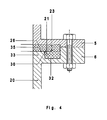
- Figure 4 shows an improved example compared to the last one described.
- the first ring 21 is seated in a recess 32 and is surrounded on three sides by material of the cylindrical portion 20.
- a projection 33 of this cylindrical portion projects into the interior of the first ring 21.
- it ends in the axial direction on the flange surface 26.
- a weld 30 connects the ring 21 and section 20.
- it fixes the arrangement, on the other hand, it seals the arrangement very well against the passage of gases.
- the weld is particularly easy to produce due to their frontal arrangement. Again, various welding methods can be used again.
- the arrangement of the weld between the projection 33 and the first ring 21 is advantageous because it is oriented to the inner side of the ring. This avoids that possibly in the space between the first ring and section 20 located gas can reach the high vacuum region.
- the first ring 21 is also concentric with the cylindrical portion 20, but this time not in a recess.
- a cutting edge 23 intersecting the metallic sealing ring 35 is provided on the flange surface 26.
- Two cutting edges 24 are provided in the direction of the cylindrical portion, depending on the space more than two cutting edges can be used to achieve a high tightness.
- the first ring is connected to the cylindrical portion via a weld 30.
- Various welding methods can be used.
- the friction stir welding can be used, which produces particularly stable and thus mechanically secure welds.
- a shit seam can also be provided on the inner circumference of the contact point between the cylindrical section and the ring.
- a second ring 22 is provided as a first measure in a recess between the cylindrical portion 20 and the first ring 21.
- This is made of mechanically softer material than the cylindrical portion and the first ring, for example made of copper.
- press cutting edges which can be provided both on the first ring and on the cylindrical portion.
- the first ring 21 is connected to the cylindrical portion via a plurality of screws 31. In the figure, the screws are drawn so that they are inserted through holes in the cylindrical section and screwed into threads in the first ring. Depending on the geometric conditions, it may be useful to provide the holes in the first ring and the threads in the cylindrical section.
- Figure 7 shows a simple solution.
- a recess 32 is provided in the cylindrical portion 21, a recess 32 is provided.
- the first ring 21 is adapted to it so that a step is created, which increases the vacuum tightness.
- the first ring is fixed by screws 31 which, as in the previous example, can either be screwed in as shown in the first ring or in the opposite direction from the flange side.
- a cutting edge 23 is provided on the flange surface 26.
Landscapes
- Engineering & Computer Science (AREA)
- General Engineering & Computer Science (AREA)
- Mechanical Engineering (AREA)
- Compressor (AREA)
- Non-Positive Displacement Air Blowers (AREA)
- Pressure Vessels And Lids Thereof (AREA)
- Compressors, Vaccum Pumps And Other Relevant Systems (AREA)
- Gasket Seals (AREA)
- Structures Of Non-Positive Displacement Pumps (AREA)
Abstract
Description
- Die Erfindung betrifft ein Vakuumgehäuse mit einem zylindrischen Abschnitt und einem Flansch.
- In der Ultrahochvakuumtechnik (UHV-Technik) müssen Metalldichtungen an den Flanschverbindungen von Vakuumkomponenten wie z.B. Vakuumkammern und Vakuumpumpen eingesetzt werden. Dies beruht auf den sehr hohen Temperturen, mit denen die UHV-Systeme ausgeheizt werden und welche für elastomere Dichtungen zu hoch sind. Zum Einsatz kommen spezielle Flansche, die aus Edelstahl hergestellt sind und Schneidkanten besitzen. Diese Schneidkanten werden in weicheres Metall gedrückt, hier findet insbesondere Kupfer Verwendung. Ein Flanschaufbau dieser Art ist in Wutz, Adam, Walcher, 8te Auflage, Seite 634 beschrieben.
- Nachteilig an diesem Stand der Technik ist, dass nicht nur die Flansche selbst aus solchen Metallen wie Edelstahl hergestellt werden müssen. Im Stand der Technik lässt es sich nicht vermeiden, die kompletten Vakuumgehäuse aus dem teueren Material herzustellen. Gerade bei großen Geräten wie Vakuumkammern aber auch bei Komponenten wie Vakuumpumpen bedeutet das ein erheblichen Kostenaufwand.
- Daher ist es Aufgabe der Erfindung, ein Vakuumgehäuse vorzustellen, was erheblich kostengünstiger und trotzdem UHV-tauglich ist.
- Gelöst wird diese Aufgabe durch ein Vakuumgehäuse mit den Merkmalen des ersten Anspruches.
- Der Grundgedanke ist, das Vakuumgehäuse mit einem Ring zu versehen, der den UHV-tauglichen Flansch voll oder in Teilen trägt. Dieser Ring ist seinerseits UHVdicht mit dem Vakuumgehäuse verbunden. Hierdurch ist es möglich, den Großteil des Gehäuses aus preisgünstigerem Material, beispielsweise Aluminium und dessen Legierungen, herzustellen.
- Die Merkmale der Unteransprüche stellen vorteilhafte Weiterbildungen der Erfindung dar.
- In einer ersten Abwandlung ist der erste Ring fest mit dem Vakuumgehäuse verbunden. Dies führt zu einer höheren Sicherheit gegen hohe mechanische Beanspruchung. Diese tritt dann auf, wenn es zu einem sogenannten Rotor/Stator-Crash einer Turbomolekularpumpe kommt, die über den Flansch mit dem Vakuumgehäuse verbunden oder sogar in ihr angeordnet ist.
- Diese Verbindung kann in einer Ausführungsform durch eine kostengünstige und trotzdem stabile Verschraubung ausgeführt sein. In einer anderen Ausführungsform wird die Verbindung über einen Pressverband ausgeführt. Denkbar ist auch, Reibrührschweißen zum Verbinden zu verwenden, da dieses unter den Schweißverfahren eine besonders sichere Verbindung herstellt.
- In einer anderen Ausführungsform weist der erste Ring neben seiner Flanschschneide eine weitere Schneide in Richtung Vakuumgehäuse auf. Hierdurch wird die Vakuumdichtheit dieser Anordnung deutlich verbessert.
- Eine Verbesserung der Vakuumdichtheit ist auch durch eine Schneide herbeizuführen, die in radialer Richtung an dem ersten Ring angebracht ist.
- Eine Verbesserung der Vakuumdichtheit ist außerdem möglich, indem ein zweiter Ring zwischen erstem Ring und Vakuumgehäuse angeordnet ist. Dieser ist aus einem Material gefertigt, welches weicher als das des Gehäuses und des ersten Ringes ist. Der zweite Ring wirkt dann als Dichtung. Vorteilhaft ist es, ihn aus Kupfer zu fertigen, da dieses eine gute Anpassung der Wärmeausdehnung an andere übliche Flansch- und Gehäusematerialien erlaubt.
- Vorteilhaft ist es weiterhin, den ersten Ring aus einem Edelstahl zu fertigen. Das Vakuumgehäuse wird vorteilhaft aus Aluminium hergestellt, da dieses gute Wärmeleiteigenschaften aufweist. Diese sind für das Ausheizen der Anlage von Vorteil.
- In einer Ausführungsform ist das Vakuumgehäuse das Gehäuse einer Vakuumkammer. Da das Gehäuse nicht aus Stahl gefertigt werden muss, die Vakuumkammer aber mitunter große Dimensionen aufweist, ist hier der Einspareffekt besonders groß.
- In einer anderen Ausführungsform ist das Vakuumgehäuse das Gehäuse einer Vakuumpumpe. Besonders vorteilhaft ist hier, dass nicht nur eine Kostenreduktion möglich wird, sondern auch ein Material eingesetzt werden kann, welches viel besser als Stahl die beim Verdichten des Gases in der Vakuumpumpe abzuführende Wärme ableiten kann.
- Mit Hilfe der Abbildungen soll die Erfindung an Ausführungsbeispielen näher erläutert und die Vorteile derselben vertieft werden. Die Abbildungen zeigen:
- Fig. 1: Eine Prinzipdarstellung einer Vakuumanlage für Ultrahochvakuum.
- Fig. 2: Schnitt durch den Flansch eines ersten Ausführungsbeispiels.
- Fig. 3: Schnitt durch den Flansch eines zweiten Ausführungsbeispiels.
- Fig. 4: Schnitt durch den Flansch eines dritten Ausführungsbeispiels.
- Fig. 5: Schnitt durch den Flansch eines vierten Ausführungsbeispiels.
- Fig. 6: Schnitt durch den Flansch eines fünften Ausführungsbeispiels.
- Fig. 7: Schnitt durch den Flansch eines sechsten Ausführungsbeispiels.
- Die erste Abbildung zeigt ein Hochvakuumsystem in einer vereinfachten, prinzipiellen Darstellung. Eine Ultrahochvakuumkammer 1, kurz: Kammer, ist mit einer Ultrahochvakuumpumpe 2, kurz: Pumpe, verbunden. Kammer und Pumpe besitzen jeweils ein Gehäuse 3 bzw. 4. Die Pumpe ist hier schematisch als Turbomolekularvakuumpumpe dargestellt, mit einem Rotor 10, welcher aus einer Welle und daran befestigten Flügeln besteht, und mit einem Stator 11, in dem Distanzringe und Flügelscheiben angeordnet sind. Der Rotor wird in Lagern 12 gelagert und über einen Antrieb 13 in schnelle Drehung versetzt. Die Pumpe weist einen Flansch 6 auf, die Kammer einen Flansch 5. Diese Flansche werden in Kontakt gebracht und über eine Mehrzahl von Flanschschrauben 7 lösbar miteinander verbunden.
- Die zweite Abbildung zeigt eine erstes Ausführungsbeispiel eines erfindungsgemäßen Vakuumgehäuses, welches sowohl das Gehäuse der Pumpe als auch der Kammer sein kann. Ein zylindrischer Abschnitt 20 ist aus einem ersten Material gefertigt, beispielsweise einer Aluminiumlegierung. Konzentrisch zu ihm sitzt ein erster Ring 21, welcher aus einem härteren Material, beispielsweise Edelstahl, gefertigt ist. Beide sind über eine Schweißnaht 30 miteinander verbunden. Verschiedene Schweißverfahren können eingesetzt werden, um diese Verbindung herzustellen. Vorteilhaft, aber nicht limitierend, ist an dieser Stelle Reibscheißen anwendbar. Der erste Ring weist eine Schneidkante 23 auf, welche auf der Fläche sitzt und ringförmig auf dieser Fläche um die Durchgangsöffnung umläuft, welche einen Teil der Flanschfläche 26 darstellt. die Schneidkanten werden beim Verbinden der Flansche in den metallischen Dichtungsring 35 gedrückt. Für diesen Dichtungsring werden mechanisch weiche Metalle benutzt, meist Kupfer 35.
- Die dritte Abbildung zeigt ein nächstes, verbessertes Ausführungsbeispiel. In dieser sitzt der erste Ring 21 innerhalb einer Ausnehmung des zylindrischen Abschnitts 20. Neben der Schneidkante 23 auf der Flanschfläche, welche in den Dichtungsring 35 schneidet, weist der Ring eine zusätzliche Schneidkante 24 in Richtung des Vakuumgehäuses auf. Eine weitere Schneidkante 25 ist am Umfang des Ringes in radialer Richtung nach außen hin angeordnet. Schon durch eine der weiteren Schneidkanten alleine werden Dichtheit und mechanische Stabilität erhöht. Zu dieser mechanischen Stabilität gehört beispielsweise, dass die Verbindung von Ring und zylindrischem Abschnitt auch dann sicher bestehen bleibt, wenn die Flanschverbindung zwischen Kammerflansch und Pumpenflansch gelöst wird. Zusammenwirkend ergibt sich eine Steigerung beider Vorteile. In diesem Beispiel ist der erste Ring eingepresst.
- Die Abbildung 4 zeigt ein gegenüber dem zuletzt beschriebenen verbessertes Beispiel. Der erster Ring 21 sitzt in einer Ausnehmung 32 und ist an drei Seiten von Material des zylindrischen Abschnitts 20 umgeben. Ein Vorsprung 33 dieses zylindrischen Abschnitts ragt in das Innere des ersten Ringes 21 hinein. Vorteilhaft endet er in axialer Richtung an der Flanschfläche 26. Eine Schweißnaht 30 verbindet Ring 21 und Abschnitt 20. Zum einen fixiert sie die Anordnung, zum anderen dichtet sie die Anordnung sehr gut gegen Durchtreten von Gasen ab. Die Schweißnaht ist aufgrund ihrer stirnseitigen Anordnung besonders einfach herzustellen. Auch hier können wieder verschiedene Schweißverfahren eingesetzt werden. Die Anordnung der Schweißnaht zwischen dem Vorsprung 33 und dem ersten Ring 21 ist vorteilhaft, da sie so zur inneren Seite des Ringes orientiert ist. Hierdurch wird vermieden, das eventuell im Raum zwischen dem ersten Ring und Abschnitt 20 befindliches Gas in den Hochvakuumbereich gelangen kann.
- In dem Ausführungsbeispiel nach Abbildung 5 sitzt der erste Ring 21 ebenfalls konzentrisch zum zylindrischen Abschnitt 20, diesmal allerdings nicht in einer Ausnehmung. Eine in den metallischen Dichtungsring 35 schneidende Schneidkante 23 ist auf der Flanschfläche 26 vorgesehen. Zwei Schneidkanten 24 sind in Richtung des zylindrischen Abschnittes vorgesehen, je nach Platzverhältnissen können mehr als zwei Schneidkanten verwendet werden, um eine hohe Dichtheit zu erreichen. In diesem Beispiel ist der erste Ring mit dem zylindrischen Abschnitt über eine Schweißnaht 30 verbunden. Verschiedene Schweißverfahren können eingesetzt werden. Vorteilhaft kann das Reibrührschweißen angewendet werden, welches besonders stabile und damit mechanisch sichere Schweißnähte erzeugt. Je nach Platz kann eine Scheißnaht auch am inneren Umfang der Kontaktstelle zwischen zylindrischem Abschnitt und Ring vorgesehen werden.
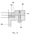
- Eine weiteres Beispiel, dargestellt in Abbildung 6, soll zwei weitere vorteilhafte Maßnahmen verdeutlichen. Zunächst wird als erste Maßnahme ein zweiter Ring 22 in einer Ausnehmung zwischen zylindrischem Abschnitt 20 und erstem Ring 21 vorgesehen. Dieser besteht aus mechanisch weicherem Material als der zylindrische Abschnitt und der erste Ring, beispielsweise aus Kupfer. In ihn drücken sich Schneidkanten, die sowohl auf dem ersten Ring als auch auf dem zylindrischen Abschnitt vorgesehen sein können. Als zweite Maßnahme ist der erste Ring 21 über eine Mehrzahl von Schrauben 31 mit dem zylindrischen Abschnitt verbunden. In der Abbildung sind die Schrauben so eingezeichnet, dass sie durch im zylindrischen Abschnitt befindliche Bohrungen gesteckt und in Gewinde im erste Ring eingeschraubt werden. Je nach geometrischen Verhältnissen kann es sinnvoll sein, die Bohrungen im ersten Ring und die Gewinde im zylindrischen Abschnitt vorzusehen.
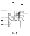
- In einem letzten Ausführungsbeispiel zeigt die Abbildung 7 eine einfache Lösung. im zylindrischen Abschnitt 21 ist eine Ausnehmung 32 vorgesehen. Der erste Ring 21 ist ihr angepasst, so dass eine Stufe entsteht, welche die Vakuumdichtheit erhöht. Der erste Ring ist durch Schrauben 31 fixiert, die wie schon im vorherigen Beispiel entweder wie eingezeichnet in den ersten Ring oder in umgekehrter Richtung von der Flanschseite her eingeschraubt werden können. Wiederum ist eine Schneidkante 23 auf der Flanschfläche 26 vorgesehen.
- Denkbar ist es, die vorgestellten Maßnahmen durch Beschichtungen zu ergänzen. Diese werden ganz oder teilweise auf den Berührungsflächen, insbesondere auf den Schneiden vorgesehen. Dies führt zu einer Härtung dieser Schneidflächen, so dass mechanische Stabilität und Dichtheit weiter verbessert werden. Natürlich ist es auch denkbar, die der Schneide gegenüberstehende Fläche geeignet zu beschichten.
- Die in den Ausführungsbeispielen beschriebenen und in den Ansprüchen vorgeschlagenen Maßnahmen können in geeigneter Weise kombiniert und angewendet werden. In diesem Sinne sind die gezeigten Beispiele nicht als Beschränkung sondern als Anregung zu verstehen.
Claims (13)
- Vakuumgehäuse (3, 4) mit einem zylindrischen Abschnitt (20) und einem Flansch (5, 6), dadurch gekennzeichnet, dass ein erster Ring (21), welcher eine ringförmige und in axialer Richtung von der Vakuumpumpe wegweisende Schneidkante (23) auf einer wenigstens zum Teil die Flanschfläche (26) bildenden Fläche besitzt, konzentrisch zum zylindrischen Abschnitt angeordnet ist und aus einem härteren Material als das Gehäuse der Vakuumpumpe besteht.
- Vakuumgehäuse nach Anspruch 1, dadurch gekennzeichnet, dass der erste Ring (21) mit dem Gehäuse verbunden ist.
- Vakuumgehäuse nach Anspruch 2, dadurch gekennzeichnet, dass der erste Ring (21) durch Schrauben (31) mit dem zylindrischen Abschnitt (20) verbunden ist.
- Vakuumgehäuse nach Anspruch 2, dadurch gekennzeichnet, dass der erste Ring (21) mit dem zylindrischen Abschnitt (20) durch einen Pressverband verbunden ist.
- Vakuumgehäuse nach einem der vorhergehenden Ansprüche, dadurch gekennzeichnet, dass der erste Ring (21) eine zweite Schneide (24) in axialer Richtung und auf das Vakuumgehäuse hinweisend aufweist.
- Vakuumgehäuse nach einem der vorhergehenden Ansprüche, dadurch gekennzeichnet, dass der erste Ring (21) eine dritte Schneide (25) ausweist, die in radialer Richtung angeordnet ist.
- Vakuumgehäuse nach einem der vorhergehenden Ansprüche, dadurch gekennzeichnet, dass ein zweiter Ring (22) in axialer Richtung zwischen erstem Ring (21) und zylindrischen Abschnitt (20) angeordnet ist und aus einem Material besteht, welches weicher als das des zylindrischen Abschnitts und des ersten Rings ist.
- Vakuumgehäuse nach Anspruch 7, dadurch gekennzeichnet, dass der zweite Ring (22) aus einer Kupferlegierung besteht.
- Vakuumgehäuse nach Anspruch 2, dadurch gekennzeichnet, dass die Verbindung zwischen zylindrischem Abschnitt (20) und erstem Ring (21) durch Reibrührschweißen entsteht.
- Vakuumgehäuse nach einem der vorhergehenden Ansprüche, dadurch gekennzeichnet, dass der erste Ring (21) aus einem Edelstahl besteht.
- Vakuumgehäuse nach einem der vorhergehenden Ansprüche, dadurch gekennzeichnet, dass der zylindrische Abschnitt (20) aus einer Aluminiumlegierung besteht.
- Vakuumgehäuse nach einem der vorhergehenden Ansprüche, dadurch gekennzeichnet, dass es das Gehäuse eine Vakuumkammer (1) ist.
- Vakuumgehäuse nach einem der vorhergehenden Ansprüche, dadurch gekennzeichnet, dass es das Gehäuse einer Vakuumpumpe (2) ist.
Applications Claiming Priority (1)
| Application Number | Priority Date | Filing Date | Title |
|---|---|---|---|
| DE102005059208A DE102005059208A1 (de) | 2005-12-12 | 2005-12-12 | Vakuumgehäuse |
Publications (3)
| Publication Number | Publication Date |
|---|---|
| EP1795757A2 true EP1795757A2 (de) | 2007-06-13 |
| EP1795757A3 EP1795757A3 (de) | 2010-05-19 |
| EP1795757B1 EP1795757B1 (de) | 2011-12-14 |
Family
ID=37814076
Family Applications (1)
| Application Number | Title | Priority Date | Filing Date |
|---|---|---|---|
| EP06023141A Not-in-force EP1795757B1 (de) | 2005-12-12 | 2006-11-07 | Vakuumpumpe |
Country Status (5)
| Country | Link |
|---|---|
| US (1) | US7495173B2 (de) |
| EP (1) | EP1795757B1 (de) |
| JP (1) | JP5512913B2 (de) |
| AT (1) | ATE537365T1 (de) |
| DE (1) | DE102005059208A1 (de) |
Cited By (5)
| Publication number | Priority date | Publication date | Assignee | Title |
|---|---|---|---|---|
| EP2068000A2 (de) * | 2007-12-08 | 2009-06-10 | Pfeiffer Vacuum GmbH | Anordnung mit Vakuumpumpe |
| DE102014110078A1 (de) * | 2014-07-17 | 2016-01-21 | Pfeiffer Vacuum Gmbh | Vakuumsystem |
| EP3051138A1 (de) * | 2015-01-27 | 2016-08-03 | Pfeiffer Vacuum Gmbh | Vakuumpumpengehäuse, Vakuumpumpe und Verfahren zur Herstellung eines Vakuumpumpengehäuses |
| WO2017025350A1 (de) * | 2015-08-12 | 2017-02-16 | Vacom Vakuum Komponenten & Messtechnik Gmbh | Nichmonolithische vakuumkammer zum ausführen von vakuumanwendungen und/oder zur aufnahme von vakuum-komponenten |
| GB2607605A (en) * | 2021-06-08 | 2022-12-14 | Leybold Gmbh | Apparatus and vacuum system |
Families Citing this family (11)
| Publication number | Priority date | Publication date | Assignee | Title |
|---|---|---|---|---|
| US20050183824A1 (en) * | 2004-02-25 | 2005-08-25 | Advanced Display Process Engineering Co., Ltd. | Apparatus for manufacturing flat-panel display |
| GB2457283B (en) * | 2008-02-08 | 2012-12-12 | Hellermann Tyton Ltd | Sealing arrangement for use in a cable enclosure port |
| US20100296249A1 (en) * | 2009-05-19 | 2010-11-25 | Beijing AVC Technology Research Center Co., Ltd. | Micro passage cold plate device for a liquid cooling radiator |
| JP5527879B2 (ja) * | 2009-11-02 | 2014-06-25 | 株式会社アルバック | フランジの製造方法 |
| US9109732B2 (en) * | 2012-04-18 | 2015-08-18 | Vistadeltek, Llc | EZ-seal gasket for joining fluid pathways |
| DE102012112492A1 (de) * | 2012-12-18 | 2014-06-18 | Pfeiffer Vacuum Gmbh | Vakuumsystem |
| EP3617523A1 (de) * | 2019-02-12 | 2020-03-04 | Pfeiffer Vacuum Gmbh | Vakuumgerät und vakuumsystem |
| US11905968B2 (en) * | 2019-03-26 | 2024-02-20 | Edwards Japan Limited | Vacuum pump, casing, and inlet port flange |
| JP7378697B2 (ja) * | 2019-03-26 | 2023-11-14 | エドワーズ株式会社 | 真空ポンプ |
| GB2592375A (en) * | 2020-02-25 | 2021-09-01 | Edwards Vacuum Llc | Flange for a vacuum apparatus |
| CN111370498B (zh) * | 2020-03-23 | 2022-05-31 | 中国科学院长春光学精密机械与物理研究所 | 一种探测器小型永久高真空腔体及制备方法 |
Citations (6)
| Publication number | Priority date | Publication date | Assignee | Title |
|---|---|---|---|---|
| US3208758A (en) * | 1961-10-11 | 1965-09-28 | Varian Associates | Metal vacuum joint |
| US3747963A (en) * | 1972-05-17 | 1973-07-24 | Cajon Co | High vacuum flange assembly with o-ring gasket |
| US3989285A (en) * | 1974-12-23 | 1976-11-02 | The United States Of America As Represented By The Secretary Of The Army | Compatible vacuum seal |
| DE3923946A1 (de) * | 1988-07-19 | 1990-01-25 | Toshiba Kawasaki Kk | Metalldichtflanschanordnung |
| US20030011143A1 (en) * | 2001-07-11 | 2003-01-16 | Satsuo Shinoda | Metallic gasket for vacuum device and method of producing thereof |
| DE69717646T2 (de) * | 1996-09-20 | 2003-07-24 | Jed Bothell | Verbindungsanordnung für ultra-hochvakuum-syteme |
Family Cites Families (8)
| Publication number | Priority date | Publication date | Assignee | Title |
|---|---|---|---|---|
| US3078332A (en) * | 1959-10-02 | 1963-02-19 | Dresser Ind | Electro-conductive pipe coupling |
| JPS4838566Y1 (de) * | 1968-08-05 | 1973-11-14 | ||
| JPS4946677B1 (de) * | 1970-12-25 | 1974-12-11 | ||
| JPH02309063A (ja) * | 1989-05-24 | 1990-12-25 | Canon Inc | 真空シール装置 |
| WO1992019891A2 (en) * | 1991-05-09 | 1992-11-12 | Bostec Engineering, Inc. | Gland and seal |
| JPH07217587A (ja) * | 1994-02-01 | 1995-08-15 | Hitachi Ltd | ターボ分子ポンプ |
| US5640751A (en) * | 1995-07-17 | 1997-06-24 | Thermionics Laboratories, Inc. | Vacuum flange |
| JP3001006B1 (ja) * | 1999-01-06 | 2000-01-17 | 日新電機株式会社 | タ―ボ分子ポンプの磁気遮蔽構造 |
-
2005
- 2005-12-12 DE DE102005059208A patent/DE102005059208A1/de not_active Withdrawn
-
2006
- 2006-11-07 AT AT06023141T patent/ATE537365T1/de active
- 2006-11-07 EP EP06023141A patent/EP1795757B1/de not_active Not-in-force
- 2006-11-17 JP JP2006311604A patent/JP5512913B2/ja active Active
- 2006-11-21 US US11/603,996 patent/US7495173B2/en not_active Expired - Fee Related
Patent Citations (6)
| Publication number | Priority date | Publication date | Assignee | Title |
|---|---|---|---|---|
| US3208758A (en) * | 1961-10-11 | 1965-09-28 | Varian Associates | Metal vacuum joint |
| US3747963A (en) * | 1972-05-17 | 1973-07-24 | Cajon Co | High vacuum flange assembly with o-ring gasket |
| US3989285A (en) * | 1974-12-23 | 1976-11-02 | The United States Of America As Represented By The Secretary Of The Army | Compatible vacuum seal |
| DE3923946A1 (de) * | 1988-07-19 | 1990-01-25 | Toshiba Kawasaki Kk | Metalldichtflanschanordnung |
| DE69717646T2 (de) * | 1996-09-20 | 2003-07-24 | Jed Bothell | Verbindungsanordnung für ultra-hochvakuum-syteme |
| US20030011143A1 (en) * | 2001-07-11 | 2003-01-16 | Satsuo Shinoda | Metallic gasket for vacuum device and method of producing thereof |
Non-Patent Citations (1)
| Title |
|---|
| JOUSTEN K: "EXCERPT FROM CHAPTER 16: BAUELEMENTE DER VAKUUMTECHNIK UND IHRE VERBINDUNGEN" WUTZ HANDBUCH VAKUUMTECHNIK. THEORIE UND PRAXIS, X, XX, Nr. 8TH ED, 1. Januar 2004 (2004-01-01), Seite 634, XP009080533 * |
Cited By (7)
| Publication number | Priority date | Publication date | Assignee | Title |
|---|---|---|---|---|
| EP2068000A2 (de) * | 2007-12-08 | 2009-06-10 | Pfeiffer Vacuum GmbH | Anordnung mit Vakuumpumpe |
| EP2068000A3 (de) * | 2007-12-08 | 2014-01-22 | Pfeiffer Vacuum GmbH | Anordnung mit Vakuumpumpe |
| DE102014110078A1 (de) * | 2014-07-17 | 2016-01-21 | Pfeiffer Vacuum Gmbh | Vakuumsystem |
| EP3051138A1 (de) * | 2015-01-27 | 2016-08-03 | Pfeiffer Vacuum Gmbh | Vakuumpumpengehäuse, Vakuumpumpe und Verfahren zur Herstellung eines Vakuumpumpengehäuses |
| WO2017025350A1 (de) * | 2015-08-12 | 2017-02-16 | Vacom Vakuum Komponenten & Messtechnik Gmbh | Nichmonolithische vakuumkammer zum ausführen von vakuumanwendungen und/oder zur aufnahme von vakuum-komponenten |
| GB2607605A (en) * | 2021-06-08 | 2022-12-14 | Leybold Gmbh | Apparatus and vacuum system |
| GB2607605B (en) * | 2021-06-08 | 2023-07-05 | Leybold Gmbh | Apparatus and vacuum system |
Also Published As
| Publication number | Publication date |
|---|---|
| JP5512913B2 (ja) | 2014-06-04 |
| US20070125515A1 (en) | 2007-06-07 |
| EP1795757A3 (de) | 2010-05-19 |
| ATE537365T1 (de) | 2011-12-15 |
| US7495173B2 (en) | 2009-02-24 |
| DE102005059208A1 (de) | 2007-06-28 |
| JP2007162682A (ja) | 2007-06-28 |
| EP1795757B1 (de) | 2011-12-14 |
Similar Documents
| Publication | Publication Date | Title |
|---|---|---|
| EP1795757B1 (de) | Vakuumpumpe | |
| EP2862262B1 (de) | Kühlmantel mit einem dichtmittel | |
| DE102014112550A1 (de) | Exzenterschneckenpumpe | |
| DE614140C (de) | Elastische Verbindung fuer Rohrleitungen mit einem U-foermigen Zwischenstueck, das mit seiner Hoehlung dem Rohrinnern zugekehrt ist und aus haerterem Material als die zu ereinigenden Rohrenden besteht | |
| EP3181827B1 (de) | Turbomaschinen-bauteilverbindung | |
| EP1731766A2 (de) | Statorscheibe für Turbomolekularpumpe | |
| EP2228540B1 (de) | Anordnung mit Vakuumpumpe | |
| DE112016004472T5 (de) | Abdichtungsstruktur für luftdichten behälter und mit der struktur versehener fahrzeug-klimakompressor | |
| EP3728910B1 (de) | Dichtungsanordnung | |
| EP2133581B1 (de) | Verbindungselement | |
| CH677009A5 (de) | ||
| DE102008050325A1 (de) | Gebautes Gehäuse, insbesondere eines Turboladers | |
| EP2954236B1 (de) | Anordnung mit einer dichtung | |
| DE69407283T2 (de) | Befestigungseinheit für ein rohr und ein verfahren zu deren herstellung | |
| WO2011064126A2 (de) | Kassettendichtung für radiallager und installationsverfahren | |
| EP3051138A1 (de) | Vakuumpumpengehäuse, Vakuumpumpe und Verfahren zur Herstellung eines Vakuumpumpengehäuses | |
| EP2789889A1 (de) | Vakuumsystem | |
| EP2131079B1 (de) | Radialwellendichtungssystem | |
| EP1798417B1 (de) | Vakuumpumpe | |
| EP2933522B1 (de) | Sattelscheibenbremse und betätigungseinrichtung einer solchen sattelscheibenbremse | |
| DE102013218904B4 (de) | Dichtungselement | |
| DE102015216819B4 (de) | Gebaute Bundlagerschale mit halbschalenförmigen Radiallagerteil und mit wenigstens einem scheibenförmigen Axiallagerteil | |
| WO2024189161A1 (de) | Flanschbauteil | |
| DE102024103290A1 (de) | Verbindungsvorrichtung zur Flanschverbindung mit zwei separaten Teilringelementen | |
| DE102015207240A1 (de) | Wärmeübertrager |
Legal Events
| Date | Code | Title | Description |
|---|---|---|---|
| PUAI | Public reference made under article 153(3) epc to a published international application that has entered the european phase |
Free format text: ORIGINAL CODE: 0009012 |
|
| AK | Designated contracting states |
Kind code of ref document: A2 Designated state(s): AT BE BG CH CY CZ DE DK EE ES FI FR GB GR HU IE IS IT LI LT LU LV MC NL PL PT RO SE SI SK TR |
|
| AX | Request for extension of the european patent |
Extension state: AL BA HR MK YU |
|
| PUAL | Search report despatched |
Free format text: ORIGINAL CODE: 0009013 |
|
| AK | Designated contracting states |
Kind code of ref document: A3 Designated state(s): AT BE BG CH CY CZ DE DK EE ES FI FR GB GR HU IE IS IT LI LT LU LV MC NL PL PT RO SE SI SK TR |
|
| AX | Request for extension of the european patent |
Extension state: AL BA HR MK RS |
|
| 17P | Request for examination filed |
Effective date: 20101119 |
|
| AKX | Designation fees paid |
Designated state(s): AT BE BG CH CY CZ DE DK EE ES FI FR GB GR HU IE IS IT LI LT LU LV MC NL PL PT RO SE SI SK TR |
|
| RIC1 | Information provided on ipc code assigned before grant |
Ipc: F04D 29/52 20060101ALI20110317BHEP Ipc: F04D 19/04 20060101AFI20110317BHEP Ipc: F04D 29/08 20060101ALI20110317BHEP Ipc: F04D 29/02 20060101ALI20110317BHEP |
|
| RTI1 | Title (correction) |
Free format text: VACUUM PUMP |
|
| GRAP | Despatch of communication of intention to grant a patent |
Free format text: ORIGINAL CODE: EPIDOSNIGR1 |
|
| GRAS | Grant fee paid |
Free format text: ORIGINAL CODE: EPIDOSNIGR3 |
|
| GRAA | (expected) grant |
Free format text: ORIGINAL CODE: 0009210 |
|
| AK | Designated contracting states |
Kind code of ref document: B1 Designated state(s): AT BE BG CH CY CZ DE DK EE ES FI FR GB GR HU IE IS IT LI LT LU LV MC NL PL PT RO SE SI SK TR |
|
| REG | Reference to a national code |
Ref country code: GB Ref legal event code: FG4D Free format text: NOT ENGLISH |
|
| REG | Reference to a national code |
Ref country code: CH Ref legal event code: EP |
|
| REG | Reference to a national code |
Ref country code: IE Ref legal event code: FG4D |
|
| REG | Reference to a national code |
Ref country code: DE Ref legal event code: R096 Ref document number: 502006010705 Country of ref document: DE Effective date: 20120209 |
|
| REG | Reference to a national code |
Ref country code: NL Ref legal event code: VDEP Effective date: 20111214 |
|
| PG25 | Lapsed in a contracting state [announced via postgrant information from national office to epo] |
Ref country code: LT Free format text: LAPSE BECAUSE OF FAILURE TO SUBMIT A TRANSLATION OF THE DESCRIPTION OR TO PAY THE FEE WITHIN THE PRESCRIBED TIME-LIMIT Effective date: 20111214 |
|
| LTIE | Lt: invalidation of european patent or patent extension |
Effective date: 20111214 |
|
| PG25 | Lapsed in a contracting state [announced via postgrant information from national office to epo] |
Ref country code: GR Free format text: LAPSE BECAUSE OF FAILURE TO SUBMIT A TRANSLATION OF THE DESCRIPTION OR TO PAY THE FEE WITHIN THE PRESCRIBED TIME-LIMIT Effective date: 20120315 Ref country code: SE Free format text: LAPSE BECAUSE OF FAILURE TO SUBMIT A TRANSLATION OF THE DESCRIPTION OR TO PAY THE FEE WITHIN THE PRESCRIBED TIME-LIMIT Effective date: 20111214 Ref country code: SI Free format text: LAPSE BECAUSE OF FAILURE TO SUBMIT A TRANSLATION OF THE DESCRIPTION OR TO PAY THE FEE WITHIN THE PRESCRIBED TIME-LIMIT Effective date: 20111214 Ref country code: NL Free format text: LAPSE BECAUSE OF FAILURE TO SUBMIT A TRANSLATION OF THE DESCRIPTION OR TO PAY THE FEE WITHIN THE PRESCRIBED TIME-LIMIT Effective date: 20111214 Ref country code: LV Free format text: LAPSE BECAUSE OF FAILURE TO SUBMIT A TRANSLATION OF THE DESCRIPTION OR TO PAY THE FEE WITHIN THE PRESCRIBED TIME-LIMIT Effective date: 20111214 |
|
| PG25 | Lapsed in a contracting state [announced via postgrant information from national office to epo] |
Ref country code: CY Free format text: LAPSE BECAUSE OF FAILURE TO SUBMIT A TRANSLATION OF THE DESCRIPTION OR TO PAY THE FEE WITHIN THE PRESCRIBED TIME-LIMIT Effective date: 20111214 |
|
| REG | Reference to a national code |
Ref country code: IE Ref legal event code: FD4D |
|
| PG25 | Lapsed in a contracting state [announced via postgrant information from national office to epo] |
Ref country code: BG Free format text: LAPSE BECAUSE OF FAILURE TO SUBMIT A TRANSLATION OF THE DESCRIPTION OR TO PAY THE FEE WITHIN THE PRESCRIBED TIME-LIMIT Effective date: 20120314 Ref country code: CZ Free format text: LAPSE BECAUSE OF FAILURE TO SUBMIT A TRANSLATION OF THE DESCRIPTION OR TO PAY THE FEE WITHIN THE PRESCRIBED TIME-LIMIT Effective date: 20111214 Ref country code: IE Free format text: LAPSE BECAUSE OF FAILURE TO SUBMIT A TRANSLATION OF THE DESCRIPTION OR TO PAY THE FEE WITHIN THE PRESCRIBED TIME-LIMIT Effective date: 20111214 Ref country code: SK Free format text: LAPSE BECAUSE OF FAILURE TO SUBMIT A TRANSLATION OF THE DESCRIPTION OR TO PAY THE FEE WITHIN THE PRESCRIBED TIME-LIMIT Effective date: 20111214 Ref country code: IS Free format text: LAPSE BECAUSE OF FAILURE TO SUBMIT A TRANSLATION OF THE DESCRIPTION OR TO PAY THE FEE WITHIN THE PRESCRIBED TIME-LIMIT Effective date: 20120414 Ref country code: EE Free format text: LAPSE BECAUSE OF FAILURE TO SUBMIT A TRANSLATION OF THE DESCRIPTION OR TO PAY THE FEE WITHIN THE PRESCRIBED TIME-LIMIT Effective date: 20111214 |
|
| PG25 | Lapsed in a contracting state [announced via postgrant information from national office to epo] |
Ref country code: PT Free format text: LAPSE BECAUSE OF FAILURE TO SUBMIT A TRANSLATION OF THE DESCRIPTION OR TO PAY THE FEE WITHIN THE PRESCRIBED TIME-LIMIT Effective date: 20120416 Ref country code: PL Free format text: LAPSE BECAUSE OF FAILURE TO SUBMIT A TRANSLATION OF THE DESCRIPTION OR TO PAY THE FEE WITHIN THE PRESCRIBED TIME-LIMIT Effective date: 20111214 Ref country code: RO Free format text: LAPSE BECAUSE OF FAILURE TO SUBMIT A TRANSLATION OF THE DESCRIPTION OR TO PAY THE FEE WITHIN THE PRESCRIBED TIME-LIMIT Effective date: 20111214 |
|
| PLBE | No opposition filed within time limit |
Free format text: ORIGINAL CODE: 0009261 |
|
| STAA | Information on the status of an ep patent application or granted ep patent |
Free format text: STATUS: NO OPPOSITION FILED WITHIN TIME LIMIT |
|
| PG25 | Lapsed in a contracting state [announced via postgrant information from national office to epo] |
Ref country code: DK Free format text: LAPSE BECAUSE OF FAILURE TO SUBMIT A TRANSLATION OF THE DESCRIPTION OR TO PAY THE FEE WITHIN THE PRESCRIBED TIME-LIMIT Effective date: 20111214 |
|
| 26N | No opposition filed |
Effective date: 20120917 |
|
| PG25 | Lapsed in a contracting state [announced via postgrant information from national office to epo] |
Ref country code: IT Free format text: LAPSE BECAUSE OF FAILURE TO SUBMIT A TRANSLATION OF THE DESCRIPTION OR TO PAY THE FEE WITHIN THE PRESCRIBED TIME-LIMIT Effective date: 20111214 |
|
| REG | Reference to a national code |
Ref country code: DE Ref legal event code: R097 Ref document number: 502006010705 Country of ref document: DE Effective date: 20120917 |
|
| PGFP | Annual fee paid to national office [announced via postgrant information from national office to epo] |
Ref country code: FR Payment date: 20121023 Year of fee payment: 7 |
|
| PG25 | Lapsed in a contracting state [announced via postgrant information from national office to epo] |
Ref country code: ES Free format text: LAPSE BECAUSE OF FAILURE TO SUBMIT A TRANSLATION OF THE DESCRIPTION OR TO PAY THE FEE WITHIN THE PRESCRIBED TIME-LIMIT Effective date: 20120325 |
|
| BERE | Be: lapsed |
Owner name: PFEIFFER VACUUM G.M.B.H. Effective date: 20121130 |
|
| PG25 | Lapsed in a contracting state [announced via postgrant information from national office to epo] |
Ref country code: FI Free format text: LAPSE BECAUSE OF FAILURE TO SUBMIT A TRANSLATION OF THE DESCRIPTION OR TO PAY THE FEE WITHIN THE PRESCRIBED TIME-LIMIT Effective date: 20111214 |
|
| REG | Reference to a national code |
Ref country code: CH Ref legal event code: PL |
|
| PG25 | Lapsed in a contracting state [announced via postgrant information from national office to epo] |
Ref country code: LI Free format text: LAPSE BECAUSE OF NON-PAYMENT OF DUE FEES Effective date: 20121130 Ref country code: CH Free format text: LAPSE BECAUSE OF NON-PAYMENT OF DUE FEES Effective date: 20121130 |
|
| PG25 | Lapsed in a contracting state [announced via postgrant information from national office to epo] |
Ref country code: BE Free format text: LAPSE BECAUSE OF NON-PAYMENT OF DUE FEES Effective date: 20121130 |
|
| REG | Reference to a national code |
Ref country code: AT Ref legal event code: MM01 Ref document number: 537365 Country of ref document: AT Kind code of ref document: T Effective date: 20121130 |
|
| PG25 | Lapsed in a contracting state [announced via postgrant information from national office to epo] |
Ref country code: AT Free format text: LAPSE BECAUSE OF NON-PAYMENT OF DUE FEES Effective date: 20121130 |
|
| PG25 | Lapsed in a contracting state [announced via postgrant information from national office to epo] |
Ref country code: MC Free format text: LAPSE BECAUSE OF NON-PAYMENT OF DUE FEES Effective date: 20121130 Ref country code: TR Free format text: LAPSE BECAUSE OF FAILURE TO SUBMIT A TRANSLATION OF THE DESCRIPTION OR TO PAY THE FEE WITHIN THE PRESCRIBED TIME-LIMIT Effective date: 20111214 |
|
| PG25 | Lapsed in a contracting state [announced via postgrant information from national office to epo] |
Ref country code: LU Free format text: LAPSE BECAUSE OF NON-PAYMENT OF DUE FEES Effective date: 20121107 |
|
| PG25 | Lapsed in a contracting state [announced via postgrant information from national office to epo] |
Ref country code: HU Free format text: LAPSE BECAUSE OF FAILURE TO SUBMIT A TRANSLATION OF THE DESCRIPTION OR TO PAY THE FEE WITHIN THE PRESCRIBED TIME-LIMIT Effective date: 20061107 |
|
| REG | Reference to a national code |
Ref country code: FR Ref legal event code: ST Effective date: 20140731 |
|
| PG25 | Lapsed in a contracting state [announced via postgrant information from national office to epo] |
Ref country code: FR Free format text: LAPSE BECAUSE OF NON-PAYMENT OF DUE FEES Effective date: 20131202 |
|
| PGFP | Annual fee paid to national office [announced via postgrant information from national office to epo] |
Ref country code: DE Payment date: 20191122 Year of fee payment: 14 |
|
| PGFP | Annual fee paid to national office [announced via postgrant information from national office to epo] |
Ref country code: GB Payment date: 20201103 Year of fee payment: 15 |
|
| REG | Reference to a national code |
Ref country code: DE Ref legal event code: R119 Ref document number: 502006010705 Country of ref document: DE |
|
| PG25 | Lapsed in a contracting state [announced via postgrant information from national office to epo] |
Ref country code: DE Free format text: LAPSE BECAUSE OF NON-PAYMENT OF DUE FEES Effective date: 20210601 |
|
| GBPC | Gb: european patent ceased through non-payment of renewal fee |
Effective date: 20211107 |
|
| PG25 | Lapsed in a contracting state [announced via postgrant information from national office to epo] |
Ref country code: GB Free format text: LAPSE BECAUSE OF NON-PAYMENT OF DUE FEES Effective date: 20211107 |