EP2228540B1 - Anordnung mit Vakuumpumpe - Google Patents
Anordnung mit Vakuumpumpe Download PDFInfo
- Publication number
- EP2228540B1 EP2228540B1 EP10002262.3A EP10002262A EP2228540B1 EP 2228540 B1 EP2228540 B1 EP 2228540B1 EP 10002262 A EP10002262 A EP 10002262A EP 2228540 B1 EP2228540 B1 EP 2228540B1
- Authority
- EP
- European Patent Office
- Prior art keywords
- flange
- pump
- chamber
- force
- vacuum pump
- Prior art date
- Legal status (The legal status is an assumption and is not a legal conclusion. Google has not performed a legal analysis and makes no representation as to the accuracy of the status listed.)
- Active
Links
Images


Classifications
-
- F—MECHANICAL ENGINEERING; LIGHTING; HEATING; WEAPONS; BLASTING
- F04—POSITIVE - DISPLACEMENT MACHINES FOR LIQUIDS; PUMPS FOR LIQUIDS OR ELASTIC FLUIDS
- F04D—NON-POSITIVE-DISPLACEMENT PUMPS
- F04D19/00—Axial-flow pumps
- F04D19/02—Multi-stage pumps
- F04D19/04—Multi-stage pumps specially adapted to the production of a high vacuum, e.g. molecular pumps
- F04D19/042—Turbomolecular vacuum pumps
-
- F—MECHANICAL ENGINEERING; LIGHTING; HEATING; WEAPONS; BLASTING
- F04—POSITIVE - DISPLACEMENT MACHINES FOR LIQUIDS; PUMPS FOR LIQUIDS OR ELASTIC FLUIDS
- F04D—NON-POSITIVE-DISPLACEMENT PUMPS
- F04D19/00—Axial-flow pumps
- F04D19/02—Multi-stage pumps
- F04D19/04—Multi-stage pumps specially adapted to the production of a high vacuum, e.g. molecular pumps
- F04D19/046—Combinations of two or more different types of pumps
-
- F—MECHANICAL ENGINEERING; LIGHTING; HEATING; WEAPONS; BLASTING
- F04—POSITIVE - DISPLACEMENT MACHINES FOR LIQUIDS; PUMPS FOR LIQUIDS OR ELASTIC FLUIDS
- F04D—NON-POSITIVE-DISPLACEMENT PUMPS
- F04D29/00—Details, component parts, or accessories
- F04D29/60—Mounting; Assembling; Disassembling
- F04D29/601—Mounting; Assembling; Disassembling specially adapted for elastic fluid pumps
Definitions
- the invention relates to an arrangement with a vacuum pump in each case according to the preamble of the independent claims 1 and 3.
- Vacuum pump and recipient assemblies hereafter referred to as chambers, are subject to a variety of geometrical design requirements.
- chambers are subject to a variety of geometrical design requirements.
- mass spectrometers there is a desire for more compact dimensions of the overall system. This often leads to a positioning of the vacuum pump in the terminal, in which their accessibility is considerably limited. Nevertheless, the service to these vacuum pumps, such as the preventive replacement of rolling bearings, should be easily possible.
- the WO 99/61799 A1 discloses a vacuum pump of an arrangement according to the preamble of claim 1.
- the US 2008/0309071 A1 discloses an assembly having a vacuum pump having a pump flange, a chamber having a chamber flange, and a flange connection comprising a pump flange and chamber flange for vacuum-sealing chamber and vacuum pump.
- the flange connection comprises a power transmission structure which transmits a force from an introduction point to an operative point located in the flange connection.
- the power transmission structure converts a planar introduction force into an axial contact force.
- the assembly includes a power transmission structure which transmits a force from a point of introduction to at least one point of action located elsewhere in the flange connection.
- a power transmission structure which transmits a force from a point of introduction to at least one point of action located elsewhere in the flange connection.
- a power transmission structure is inexpensive to produce and avoids expensive designs of the vacuum pump, in particular its vacuum-tight housing.
- the pump flange comprises at least two suction openings.
- the arrangement is cost-effective, because the power transmission structure is adapted to implement a planar initiating force in an axial contact force.
- Planar here means that the direction of force lies in a plane parallel to the flange plane.
- Axial means standing vertically on the flange plane.
- Claim 3 proposes to provide a lever mechanism which transmits the force introduced at one location of the flange connection to another location of the flange connection.
- a damping element in the power transmission structure provides for reduced vibration transmission across the flange connection. This allows the use of the assembly in applications that are sensitive to shocks.
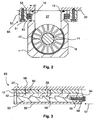
- FIG Fig. 1 An exemplary overall system with an arrangement of vacuum pump and chamber is shown in FIG Fig. 1 shown.
- the chamber 2 is designed as a multi-chamber system for differential pumping and therefore has a fore-vacuum chamber 21, a central chamber 22 and a high-vacuum chamber 23. These chambers are interconnected via openings 25 and 26 through which, for example, a gas particle jet passes.
- a detector for example a mass spectrometer 24, is provided, which is controlled by a drive assembly 36.
- the chamber has a chamber flange 20 with which a pump flange 10 is connected.
- the pump flange is part of the vacuum pump 1, which comprises a shaft 11 which is rotatably supported by a fore vacuum side bearing 12, for example a roller bearing, and a high vacuum side bearing 13, for example a permanent magnet bearing.
- the shaft is rotated by a drive 14 in rotation, so that in the pumping stages 15 and 16, compression and suction capacity are built up.
- the inlet of the pumping stage 15 is connected via an intake port 27 to the central chamber in connection.
- the pumping stage 16 is in turn connected via a suction port 28 with the high vacuum chamber 23 in connection. Gas enters through the suction port 28 in the vacuum pump, is compressed by the pumping stage 16, then merged with the entering through the suction port 27 into the vacuum pump gas and further compressed together with this of the pumping stage 15.
- Outlet of the vacuum pump and Vorvakuumhunt 21 are connected via a Vorvakuumzutechnisch 41 with a backing pump 40, which further compresses the gas and expels against the atmosphere.
- the pumping stages 15 and 16 are preferably designed as turbomolecular pumping stages.
- the vacuum pump and chamber connected together by the vacuum-tight and chamber flange and pump flange are supported by a frame 30.
- This frame also carries the drive assembly 36 of the mass spectrometer and further components 33, 34 and 35, such as power supplies, computing units and the like.
- the frame is covered with a panel 31.
- Vacuum pump and chamber are accessible by a flap 32, but surrounded by the other supported by the frame assemblies and components. The flange is therefore difficult and essentially accessible only from the side facing the flap 32. Assembly and disassembly of the vacuum pump can therefore only be done from this side.
- FIG. 2 It shows Fig. 2 the power transmission structure 65 in cross section to the shaft 11 by vacuum pump and flange connection along the line I-I '.
- Chamber flange 20 and pump flange 10 touch each other.
- a Seal 19 is provided, which surrounds the suction port 27 on the flange.
- a fixing screw 51 attaches a bracket 50 on the chamber flange. Between the bracket and the pump flange, a first expansion element 52 and a second expansion element 53 are arranged.
- Fig. 3 is the corresponding section along the line II-II 'and shown parallel to the shaft. It will be appreciated that a portion of the bracket 50, first expansion member 52, second expansion member 53, and a portion of the pump flange 10 lie in a common plane.
- the first expansion element has a wedge surface 58 and the second expansion element has a wedge surface 58 '. These wedge surfaces touch each other so that a shift against each other is possible.
- the displacement is effected by a force introduction screw 55, which projects through a through hole in an arm 54 of the first expansion element, and engages the threaded part in a thread of the second expansion element. By tightening the screw, a planar force is exerted, which shifts the two expansion elements against each other.
- the spreading elements 52 and 53 cause a force in the force transmission structure 65 to be transferred from the point of introduction 56 to a point of action 59.
- This power transmission makes it possible to generate a contact pressure 60 also in the places which are related by FIG. 1 described and surrounding the vacuum pump components are not accessible.
- Another advantage of this example is that in addition to the power transmission and a force distribution over the pump flange takes place and so a uniform contact pressure is achieved. With the number of wedge surfaces and their angle, the force distribution of the force introduced on the flange 10 can be adjusted.
- the bracket can be made in one piece with the chamber flange. A separation is advantageous if an existing system is to be retrofitted. In addition, omitted in the design according to this example changes the pump flange, so that a standard pump can be used.
- the number of pumping stages of the vacuum pump and the number of gas inlets is only an example and not a limitation.
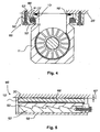
- FIGS. 4 and 5 A development of this embodiment show the FIGS. 4 and 5 , The pump flange 10 'of the vacuum pump 1' is not completely pulled in this development against the chamber flange 20 '. Between pump flange and chamber flange remains a gap which is created by the seal 19 '. The force introduced and transmitted via the force transmission structure 65 'is therefore such that the seal 19' is not squeezed to the touch of the flanges. However, the contact pressure and thus pinch seal is sufficient to ensure a vacuum-tight connection.
- the power transmission structure has here also spreading 52 'and 53', which are provided between the pump flange and the bracket 50 '.
- a damping element 66 ' is arranged between the first expansion element 52' and the flange.
- FIG. 5 A section along the line III-III 'by this development is in Fig. 5 shown. Between chamber flange 20 'and pump flange 10', the gap 67 'is provided.
- the damping element 66' is arranged between the pump flange and the first expansion element 52 '.
- the spreading 52 'and 53' act with pump flange, chamber flange and bracket as in the FIGS. 2 and 3 described together.
- the damping element causes together with the seal an advantageous vibration isolation. Vibrations, which are generated for example by the rapid rotation of the shaft in the vacuum pump, are transmitted by damping element and seal only to a greatly reduced extent, so that this arrangement brings an advantage in vibration critical applications.
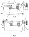
- FIGS. 6 and 7 Another example of power transmission structure show the FIGS. 6 and 7 , In Fig. 6 First, a longitudinal section along the shaft 111 of the vacuum pump 100 is shown.
- the vacuum pump has two pumping stages 115 and 116. The leading to the pumping stages gas inlets are surrounded by seals 119.
- the pump flange 110 has a flange extension 152. This is engaged with a counter-angle 150, wherein in Fig. 6 the dismantled state is shown. The counter-angle is fastened with a fastening screw 151 on the chamber flange 120.
- Fig. 7 is the arrangement after Fig. 6 shown in the assembled state.
- the pump flange is screwed to the chamber flange 120 and introduced an axial force 162 at the point of introduction 156
- the flange extension and the counter angle act as a lever mechanism and generate at the point of action 159 an axial contact pressure 160.
- the lever mechanism causes in the power transmission structure 165 a Force is transmitted from the point of introduction 156 to an active site 159. This power transmission makes it possible to generate a contact pressure 160 also in the places associated with FIG. 1 described and surrounding the vacuum pump components are not accessible.
- the counter-angle can be made in one piece with the chamber flange. A separation is advantageous if an existing system is to be retrofitted.
- the number of pumping stages of the vacuum pump and the number of gas inlets is only an example and not a restriction.
- a damping element can be arranged, which cooperates with the seal as in the development of the first example and thus creates a vibration-decoupled flange connection.
- FIG. 8 The principle of action of the first example FIGS. 2 and 3 , whose training after 4 and 5 and the second example 6 and 7 is in FIG. 8 shown.
- the flange has suction openings 71 and 72, via which pump stages for a medium and higher vacuum are accessible.
- the flange has a circumference formed by the edges 75, 76, 77 and 78. In the in FIG. 1 shown installation position of the vacuum pump, only the edge 76 is accessible for mounting and dismounting the vacuum pump. For this flange to enter into a vacuum-tight flange connection with the flange of the chamber, a substantially perpendicular contact force must act on all edges along the edges.
- the power transmission structure makes it possible to initiate a force in a first section 80 of the circumference and to bring it into effect in another section 81, which is different from the first section, and in particular to generate an axial contact pressure 87 there.
- the first section can be a planar force 86, as explained in the first example, or an axial force 85, as explained in the second example.
- the measures can be used together with known fasteners such as clamp screws and claws.
Landscapes
- Engineering & Computer Science (AREA)
- Mechanical Engineering (AREA)
- General Engineering & Computer Science (AREA)
- Compressors, Vaccum Pumps And Other Relevant Systems (AREA)
- Applications Or Details Of Rotary Compressors (AREA)
Description
- Die Erfindung betrifft eine Anordnung mit Vakuumpumpe jeweils nach dem Oberbegriff der unabhängigen Ansprüche 1 und 3.
- Anordnungen mit Vakuumpumpe und Rezipienten, im folgenden Kammer genannt, unterliegen einer Vielzahl von Anforderungen hinsichtlich ihrer geometrischen Gestaltung. So besteht beispielsweise im Bau von Massenspektrometern der Wunsch nach kompakteren Abmessungen des Gesamtsystems. Dies führt oftmals zu einer Positionierung der Vakuumpumpe im Endgerät, bei der ihre Zugänglichkeit erheblich eingeschränkt ist. Trotzdem soll der Service an diesen Vakuumpumpen, beispielsweise der präventive Austausch von Wälzlagern, leicht möglich sein.
- Dieser Widerspruch wird im Stand der Technik durch eine Konstruktion aufgelöst, bei der die Vakuumpumpe ein Doppelgehäuse besitzt. Ein Beispiel solch eines Aufbaus stellt die
WO 99/61799 A1 - Diese Konstruktion ist sehr aufwändig, da zusätzliche Gehäusebauteile geschaffen werden müssen. Um die Gefahr von virtuellen Lecks zu verringern, müssen eine Vielzahl von Dichtungen vorhanden sein, außerdem ist eine hinreichende Genauigkeit bei der Herstellung unabdingbar. Dies treibt die Herstellungskosten in die Höhe.
- Die
WO 99/61799 A1 - Die
US 2008/0309071 A1 offenbart eine Anordnung mit einer Vakuumpumpe, welche einen Pumpenflansch aufweist, einer Kammer, welche einen Kammerflansch aufweist, und einer Pumpenflansch und Kammerflansch umfassenden Flanschverbindung zur vakuumdichten Verbindung von Kammer und Vakuumpumpe. Die Flanschverbindung umfasst eine Kraftübertragungsstruktur, welche eine Kraft von einer Einleitungsstelle an eine in der Flanschverbindung liegende Wirkstelle überträgt. Die Kraftübertragungsstruktur setzt eine planare Einleitkraft in eine axiale Anpresskraft um. - Es ist Aufgabe der Erfindung, eine Anordnung vorzustellen, die eine gute Montierbarkeit von Pumpen ermöglicht aber eine einfache Konstruktion aufweist.
- Gelöst wird diese Aufgabe durch eine Anordnung mit den Merkmalen des ersten Anspruchs. Die abhängigen Ansprüche 2, 4 und 5 geben vorteilhafte Weiterbildungen an.
- Die Anordnung weist eine Kraftübertragungsstruktur auf, welche eine Kraft von einer Einleitungsstelle an wenigsten einen an anderer Stelle in der Flanschverbindung liegenden Wirkpunkt überträgt. Durch diesen Aufbau ist es möglich, die in der Flanschverbindung notwendige Anpresskraft an jeder Stelle dieser Flanschverbindung zu erzeugen, ohne dass die betreffende Stelle direkt zugänglich ist. Auf diese Weise kann die vakuumdichte Befestigung der Vakuumpumpe von einer ihrer Seiten aus bewerkstelligt werden. Zur Montage und Demontage muss dann lediglich diese Seite zugänglich sein. Die Anforderungen an leichte Erreich- und Austauschbarkeit der Vakuumpumpe sind erfüllt.
- Eine Kraftübertragungsstruktur ist kostengünstig herstellbar und vermeidet teure Gestaltungen der Vakuumpumpe, insbesondere deren vakuumdichten Gehäuses.
- Der Pumpenflansch umfasst wenigstens zwei Ansaugöffnungen.
- Die Anordnung ist kostengünstig, denn die Kraftübertragungsstruktur ist angepasst, eine planare Einleitkraft in eine axiale Anpresskraft umzusetzen. Planar bedeutet hier, dass die Kraftrichtung in einer zur Flanschebene parallelen Ebene liegt. Axial bedeutet senkrecht auf der Flanschebene stehend. Diese Lösung ist kostengünstig durch Spreizelemente umsetzbar. In einer Weiterbildung weisen die Spreizelemente sich berührende Keilflächen auf.
- Gelöst wird die Aufgabe außerdem durch eine Anordnung mit den Merkmalen des Anspruchs 3. Die abhängigen Ansprüche 4 und 5 geben auch hier vorteilhafte Weiterbildungen an.
- Anspruch 3 schlägt vor, einen Hebelmechanismus zu schaffen, der die an einer Stelle der Flanschverbindung eingeleitete Kraft an eine andere Stelle der Flanschverbindung überträgt.
- Ein Dämpfungselement in der Kraftübertragungsstruktur sorgt für eine verringerte Schwingungsübertragung über die Flanschverbindung. Dies ermöglicht den Einsatz der Anordnung in Anwendungen, die empfindlich auf Erschütterungen reagieren.
- An Hand von Ausführungsbeispielen und deren Weiterbildungen soll die Erfindung näher erläutert und die Darstellung ihrer Vorteile vertieft werden.
- Es zeigen:
- Fig. 1:
- Darstellung einer Anordnung mit Kammer und Vakuumpumpe gemäß Anspruch 1 in einem Gesamtsystem,
- Fig. 2:
- Schnitt durch die Flanschverbindung entlang der Linie I-I' in einem ersten Ausführungsbeispiel,
- Fig. 3:
- Schnitt durch die Flanschverbindung des ersten Ausführungsbeispiels entlang der Linie II-II',
- Fig. 4:
- Schnitt durch die Flanschverbindung des ersten Ausführungsbeispiels in einer Weiterbildung,
- Fig. 5:
- Schnitt durch die Weiterbildung entlang der Linie III-III',
- Fig. 6:
- Längsschnitt durch eine Flanschverbindung gemäß Anspruch 3, demontierter Zustand der Anordnung,
- Fig. 7:
- Schnitt durch die Flanschverbindung der
Fig. 6 , montierter Zustand, - Fig. 8:
- Schematische Darstellung eines Flansches.
- Ein beispielhaftes Gesamtsystem mit einer Anordnung aus Vakuumpumpe und Kammer ist in
Fig. 1 dargestellt. - Die Kammer 2 ist als Mehrkammersystem zum differentiellen Pumpen gestaltet und weist daher eine Vorvakuumkammer 21, eine Mittelkammer 22 und eine Hochvakuumkammer 23 auf. Diese Kammern sind über Öffnungen 25 und 26 miteinander verbunden, durch welche beispielsweise ein Gasteilchenstrahl hindurchtritt. In der Hochvakuumkammer ist ein Detektor, beispielsweise ein Massenspektrometer 24, vorgesehen, welches von einer Ansteuerungsbaugruppe 36 angesteuert wird. Die Kammer weist einen Kammerflansch 20 auf, mit welchem ein Pumpenflansch 10 verbunden ist.
- Der Pumpenflansch ist Teil der Vakuumpumpe 1, welche eine Welle 11 umfasst, die mit einem vorvakuumseitigen Lager 12, beispielsweise einem Wälzlager, und einem hochvakuumseitigen Lager 13, beispielsweise einem Permanentmagnetlager, drehbar unterstützt ist. Die Welle wird von einem Antrieb 14 in Drehung versetzt, so dass in den Pumpstufen 15 und 16 Kompression und Saugvermögen aufgebaut werden.
- Der Einlass der Pumpstufe 15 steht über eine Ansaugöffnung 27 mit der Mittelkammer in Verbindung. Die Pumpstufe 16 steht ihrerseits über eine Ansaugöffnung 28 mit der Hochvakuumkammer 23 in Verbindung. Gas tritt durch die Ansaugöffnung 28 in die Vakuumpumpe ein, wird durch die Pumpstufe 16 verdichtet, danach mit dem durch die Ansaugöffnung 27 in die Vakuumpumpe eintretenden Gas zusammengeführt und gemeinsam mit diesem von der Pumpstufe 15 weiterverdichtet. Auslass der Vakuumpumpe und Vorvakuumkammer 21 sind über eine Vorvakuumzuleitung 41 mit einer Vorpumpe 40 verbunden, welche das Gas weiter verdichtet und gegen Atmosphäre ausstößt. Die Pumpstufen 15 und 16 sind vorzugsweise als Turbomolekularpumpstufen gestaltet.
- Die miteinander durch die vakuumdichte und Kammerflansch und Pumpenflansch umfassende Flanschverbindung 3 verbundenen Vakuumpumpe und Kammer werden von einem Gestell 30 getragen. Dieses Gestell trägt zudem die Ansteuerungsbaugruppe 36 des Massenspektrometers sowie weiter Komponenten 33, 34 und 35, beispielsweise Netzteile, Recheneinheiten und dergleichen mehr. Das Gestell ist mit einer Verkleidung 31 abgedeckt. Vakuumpumpe und Kammer sind durch eine Klappe 32 zugänglich, jedoch von den anderen vom Gestell getragenen Baugruppen und Komponenten umgeben. Die Flanschverbindung ist daher schwer und im wesentlichen nur von der Seite zugänglich, die der Klappe 32 zugewandt ist. Montage und Demontage der Vakuumpumpe können daher nur von dieser Seite erfolgen.
- Diese Art der Montage wird problemlos durch die Kraftübertragungsstruktur gemäß erster Lösung nach
Fig. 2 und 3 ermöglicht. - Es zeigt
Fig. 2 die Kraftübertragungsstruktur 65 im Querschnitt zur Welle 11 durch Vakuumpumpe und Flanschverbindung entlang der Linie I-I'. Kammerflansch 20 und Pumpenflansch 10 berühren einander. Zur vakuumdichten Verbindung ist eine Dichtung 19 vorgesehen, die die Ansaugöffnung 27 am Flansch umgibt. In der Vakuumpumpe 1 sind in diesem Schnitt die zwischen den Pumpstufen vorgesehene und deren Komponenten beabstandende Distanzhülse 18 und die letzte Statorscheibe 17 der hochvakuumseitigen Pumpstufe zu sehen. Eine Befestigungsschraube 51 befestigt einen Haltewinkel 50 am Kammerflansch. Zwischen dem Haltewinkel und dem Pumpenflansch sind ein erstes Spreizelement 52 und ein zweites Spreizelement 53 angeordnet. - In
Fig. 3 ist der dazugehörige Schnitt entlang der Linie II-II' und parallel zur Welle gezeigt. Es wird ersichtlich, dass ein Teil des Haltewinkels 50, erstes Spreizelement 52, zweites Spreizelement 53 und ein Teil des Pumpenflansches 10 in einer gemeinsamen Ebene liegen. Das erste Spreizelement weist eine Keilfläche 58 und das zweite Spreizelement eine Keilfläche 58' auf. Diese Keilflächen berühren einander derart, dass eine Verschiebung gegeneinander möglich ist. Bewirkt wird die Verschiebung durch eine Krafteinleitungsschraube 55, die durch eine Durchgangsbohrung in einem Arm 54 des ersten Spreizelementes hindurchragt, und deren Gewindeteil in ein Gewinde des zweiten Spreizelementes eingreift. Durch Anziehen der Schraube wird eine planare Kraft ausgeübt, die die beiden Spreizelemente gegeneinander verschiebt. Durch Wirkung der Keilflächen wird die Kraftrichtung in eine axiale Richtung umgewandelt. Es wird dann eine axiale Anpresskraft 60 an der Wirkstelle 59 erzeugt, die Pumpenflansch und Kammerflansch 20 gegeneinander drückt und so für die vakuumdichte Verbindung sorgt. Durch die Spreizelemente findet eine Kraftrichtungsumsetzung statt. Montage beziehungsweise Demontage der Vakuumpumpe werden über Anziehen beziehungsweise Lösen der Schraube 55 erreicht. - Die Spreizelemente 52 und 53 bewirken, dass in der Kraftübertragungsstruktur 65 eine Kraft von der Einleitungsstelle 56 an eine Wirkstelle 59 übertragen wird. Diese Kraftübertragung erlaubt es, eine Anpresskraft 60 auch an den Stellen zu erzeugen, die durch die im Zusammenhang mit
Figur 1 beschriebenen und die Vakuumpumpe umgebenden Komponenten nicht zugänglich sind. Vorteilhaft an diesem Beispiel ist zudem, dass neben der Kraftübertragung auch eine Kraftverteilung über den Pumpenflansch stattfindet und so eine gleichmäßige Anpressung erzielt wird. Mit der Anzahl der Keilflächen und deren Winkel kann die Kraftverteilung der eingeleiteten Kraft auf den Flansch 10 eingestellt werden. - Der Haltewinkel kann einstückig mit dem Kammerflansch ausgeführt sein. Eine Trennung ist dann von Vorteil, wenn ein bestehendes System nachgerüstet werden soll. Zudem entfallen bei der Gestaltung gemäß dieses Beispiels Veränderungen des Pumpenflansches, so dass eine serienmäßige Pumpe zum Einsatz kommen kann. Die Zahl der Pumpstufen der Vakuumpumpe und die Zahl der Gaseinlässe ist hier nur beispielhaft und stellen keine Beschränkung dar.
- Eine Weiterbildung dieses Ausführungsbeispiels zeigen die
Figuren 4 und 5 . Der Pumpenflansch 10' der Vakuumpumpe 1' ist in dieser Weiterbildung nicht vollständig gegen den Kammerflansch 20' gezogen. Zwischen Pumpenflansch und Kammerflansch verbleibt ein Spalt, welcher durch die Dichtung 19' geschaffen wird. Die eingeleitete und über die Kraftübertragungsstruktur 65' übertragene Kraft ist daher so bemessen, dass die Dichtung 19' nicht bis zum Berühren der Flansche zusammengequetscht ist. Jedoch ist die Anpresskraft und damit Quetschung der Dichtung ausreichend, eine vakuumdichte Verbindung zu gewährleisten. Die Kraftübertragungsstruktur weist auch hier Spreizelemente 52' und 53' auf, die zwischen dem Pumpenflansch und dem Haltewinkel 50' vorgesehen sind. Zusätzlich ist zwischen dem ersten Spreizelement 52' und dem Flansch ein Dämpfungselement 66' angeordnet. - Ein Schnitt entlang der Linie III-III' durch diese Weiterbildung ist in
Fig. 5 gezeigt. Zwischen Kammerflansch 20' und Pumpenflansch 10' ist der Spalt 67' vorgesehen. - Zwischen Pumpenflansch und erstem Spreizelement 52' ist das Dämpfungselement 66' angeordnet. Die Spreizelemente 52' und 53' wirken mit Pumpenflansch, Kammerflansch und Haltewinkel wie bei den
Figuren 2 und 3 beschrieben zusammen. Das Dämpfungselement bewirkt zusammen mit der Dichtung eine vorteilhafte Schwingungsentkopplung. Schwingungen, die beispielsweise durch die schnelle Drehung der Welle in der Vakuumpumpe erzeugt werden, werden durch Dämpfungselement und Dichtung lediglich in stark vermindertem Maße übertragen, so dass diese Anordnung bei schwingungskritischen Anwendungen einen Vorteil bringt. - Eine weiteres Beispiel für Kraftübertragungsstruktur zeigen die
Figuren 6 und 7 . InFig. 6 ist zunächst ein Längsschnitt entlang der Welle 111 der Vakuumpumpe 100 gezeigt. Die Vakuumpumpe weist zwei Pumpstufen 115 und 116 auf. Die zu den Pumpstufen führenden Gaseinlässe sind von Dichtungen 119 umgeben. Der Pumpenflansch 110 weist eine Flanschfortsatz 152 auf. Dieser wird mit einem Gegenwinkel 150 in Eingriff gebracht, wobei inFig. 6 der demontierte Zustand gezeigt ist. Der Gegenwinkel ist mit einer Befestigungsschraube 151 am Kammerflansch 120 befestigt. - In
Fig. 7 ist die Anordnung nachFig. 6 im montierten Zustand dargestellt. Mittels einer Sicherungsschraube 161 wird der Pumpenflansch am Kammerflansch 120 angeschraubt und eine Axialkraft 162 an der Einleitungsstelle 156 eingeleitet Der Flanschfortsatz und der Gegenwinkel wirken als Hebelmechanismus zusammen und erzeugen an der Wirkstelle 159 eine axiale Anpresskraft 160. Der Hebelmechanismus bewirkt, dass in der Kraftübertragungsstruktur 165 eine Kraft von der Einleitungsstelle 156 an eine Wirkstelle 159 übertragen wird. Diese Kraftübertragung erlaubt es, eine Anpresskraft 160 auch an den Stellen zu erzeugen, die durch die im Zusammenhang mitFigur 1 beschriebenen und die Vakuumpumpe umgebenden Komponenten nicht zugänglich sind. - Der Gegenwinkel kann einstückig mit dem Kammerflansch ausgeführt sein. Eine Trennung ist dann von Vorteil, wenn ein bestehendes System nachgerüstet werden soll. Die Zahl der Pumpstufen der Vakuumpumpe und die Zahl der Gaseinlässe ist hier nur beispielhaft und stellen keine Beschränkung dar. Zwischen Gegenwinkel und Flanschfortsatz kann ein Dämpfungselement angeordnet sein, welches wie in der Weiterbildung des ersten Beispiels mit der Dichtung zusammenwirkt und so eine schwingungsentkoppelte Flanschverbindung schafft.
- Das Wirkprinzip des ersten Beispiels nach
Fig. 2 und 3 , dessen Weiterbildung nachFig. 4 und 5 und des zweiten Beispiels nachFig. 6 und 7 ist inFigur 8 dargestellt. In dieser perspektivischen Darstellung ist die dem Kammerflansch zugewandte Oberfläche des Pumpenflansches 70 dargestellt. Der Flansch weist Ansaugöffnungen 71 und 72 auf, über welche Pumpstufen für ein mittleres und höheres Vakuum zugänglich sind. Der Flansch besitzt einen Umfang, der durch die Kanten 75, 76, 77 und 78 gebildet wird. In der inFigur 1 dargestellten Einbaulage der Vakuumpumpe ist nur die Kante 76 für die Montage und Demontage der Vakuumpumpe zugänglich. Damit dieser Flansch eine vakuumdichte Flanschverbindung mit dem Flansch der Kammer eingeht, muss entlang aller Kanten eine im wesentlichen senkrecht auf den Flansch stehende und somit axiale Anpresskraft wirken. Dies erzeugt eine flächige Anpressung der Pumpenflansches an den Kammerflansch. Die Kraftübertragungsstruktur ermöglicht es, eine Kraft in einem ersten Abschnitt 80 des Umfangs einzuleiten und an einer in einem anderen, vom ersten Abschnitt verschiedenen Abschnitt 81 zur Wirkung zu bringen, insbesondere dort eine axiale Anpresskraft 87 zu erzeugen. Die im ersten Abschnitt kann dabei ein planare Kraft 86 sein, wie im ersten Beispiel erläutert, oder eine axiale Kraft 85 sein, wie im zweiten Beispiel erläutert. - Weiterhin können die Maßnahmen zusammen mit bekannten Befestigungselementen wie Klammerschrauben und Pratzen verwendet werden.
Claims (5)
- Anordnung mit einer Vakuumpumpe (1), welche einen Pumpenflansch (10; 70) aufweist, einer Kammer (2), welche einen Kammerflansch (20) aufweist, und einer Pumpenflansch und Kammerflansch umfassenden Flanschverbindung (3) zur vakuumdichten Verbindung von Kammer und Vakuumpumpe, wobei die Anordnung eine Kraftübertragungsstruktur (65) umfasst, welche eine Kraft von einer Einleitungsstelle (56) an wenigstens eine in der Flanschverbindung liegende Wirkstelle (59) überträgt, wobei der Pumpenflansch (10; 70) wenigstens zwei Ansaugöffnungen (27; 28) umfasst, welche jeweils mit einer Pumpstufe (15, 16) verbunden sind, dadurch gekennzeichnet, dass die Kraftübertragungsstruktur (65) angepasst ist, eine planare Einleitkraft (57; 86) in eine axiale Anpresskraft (60; 87) umzusetzen.
- Anordnung nach Anspruch 1, dadurch gekennzeichnet, dass die Kraftübertragungsstruktur (65) ein erstes Spreizelement (52) mit einer ersten Keilfläche (58) und ein zweites Spreizelement (53) mit einer zweiten Keilfläche (58') umfasst, wobei sich die Keilflächen (58, 58') berühren.
- Anordnung mit einer Vakuumpumpe (100), welche einen Pumpenflansch (110; 70) aufweist, einer Kammer (2), welche einen Kammerflansch (120) aufweist, und einer Pumpenflansch und Kammerflansch umfassenden Flanschverbindung zur vakuumdichten Verbindung von Kammer und Vakuumpumpe, wobei die Anordnung eine Kraftübertragungsstruktur (165) umfasst, welche eine Kraft von einer Einleitungsstelle (156) an wenigstens eine in der Flanschverbindung liegende Wirkstelle (159) überträgt, wobei der Pumpenflansch (110; 70) wenigstens zwei Ansaugöffnungen umfasst, welche jeweils mit einer Pumpstufe (115, 116) verbunden sind, dadurch gekennzeichnet, dass die Kraftübertragungsstruktur (165) einen Flanschfortsatz (152) und einen Gegenwinkel (150) umfasst, wobei Flanschfortsatz und Gegenwinkel einen Hebelmechanismus bilden.
- Anordnung nach einem der vorhergehenden Ansprüche, dadurch gekennzeichnet, dass die Kraftübertragungsstruktur (65; 165) eingerichtet ist, eine in einem ersten Abschnitt (80) der Flanschverbindung eingeleitete Kraft (85; 86) in einen zweiten, vom ersten verschiedenen, Abschnitt (81) zu übertragen.
- Anordnung nach einem der vorhergehenden Ansprüche, dadurch gekennzeichnet, dass die Kraftübertragungsstruktur (65; 165) ein Dämpfungselement (66') umfasst.
Applications Claiming Priority (1)
| Application Number | Priority Date | Filing Date | Title |
|---|---|---|---|
| DE200910013244 DE102009013244A1 (de) | 2009-03-14 | 2009-03-14 | Anordnung mit Vakuumpumpe |
Publications (3)
| Publication Number | Publication Date |
|---|---|
| EP2228540A2 EP2228540A2 (de) | 2010-09-15 |
| EP2228540A3 EP2228540A3 (de) | 2014-07-16 |
| EP2228540B1 true EP2228540B1 (de) | 2016-08-03 |
Family
ID=42154832
Family Applications (1)
| Application Number | Title | Priority Date | Filing Date |
|---|---|---|---|
| EP10002262.3A Active EP2228540B1 (de) | 2009-03-14 | 2010-03-05 | Anordnung mit Vakuumpumpe |
Country Status (2)
| Country | Link |
|---|---|
| EP (1) | EP2228540B1 (de) |
| DE (1) | DE102009013244A1 (de) |
Families Citing this family (6)
| Publication number | Priority date | Publication date | Assignee | Title |
|---|---|---|---|---|
| GB2516969B (en) * | 2013-08-09 | 2017-04-19 | Edwards Ltd | Vacuum system securing devices |
| DE102013109637A1 (de) * | 2013-09-04 | 2015-03-05 | Pfeiffer Vacuum Gmbh | Vakuumpumpe sowie Anordnung mit einer Vakuumpumpe |
| DE102013222167B4 (de) | 2013-10-31 | 2024-07-11 | Pfeiffer Vacuum Gmbh | Vakuumpumpe |
| EP3026303B1 (de) * | 2014-11-28 | 2021-01-06 | Pfeiffer Vacuum Gmbh | Vakuumpumpe, vakuumzubehör und dichtung zu dessen abdichtung |
| EP3702622B1 (de) * | 2019-02-26 | 2026-02-25 | Pfeiffer Vacuum Gmbh | Vakuumsystem |
| EP3763944B1 (de) * | 2020-03-31 | 2022-09-07 | Pfeiffer Vacuum Technology AG | Befestigungsschiene mit exzentereinrichtung |
Family Cites Families (3)
| Publication number | Priority date | Publication date | Assignee | Title |
|---|---|---|---|---|
| WO1999061799A1 (de) | 1998-05-26 | 1999-12-02 | Leybold Vakuum Gmbh | Reibungsvakuumpumpe mit chassis, rotor und gehäuse sowie einrichtung, ausgerüstet mit einer reibungsvakuumpumpe dieser art |
| DE102005020904A1 (de) * | 2005-05-07 | 2006-11-09 | Leybold Vacuum Gmbh | Vakuum-Pumpenanordnung |
| EP2017480A1 (de) * | 2007-06-15 | 2009-01-21 | VARIAN S.p.A. | Geteilte Verbindung für Vakuumpumpen und Verfahren zur Gewinnung der besagten Verbindung |
-
2009
- 2009-03-14 DE DE200910013244 patent/DE102009013244A1/de active Pending
-
2010
- 2010-03-05 EP EP10002262.3A patent/EP2228540B1/de active Active
Also Published As
| Publication number | Publication date |
|---|---|
| EP2228540A3 (de) | 2014-07-16 |
| EP2228540A2 (de) | 2010-09-15 |
| DE102009013244A1 (de) | 2010-09-16 |
Similar Documents
| Publication | Publication Date | Title |
|---|---|---|
| EP2228540B1 (de) | Anordnung mit Vakuumpumpe | |
| EP2846044B1 (de) | Vakuumpumpe sowie anordnung mit einer vakuumpumpe | |
| EP1090231A1 (de) | Reibungsvakuumpumpe mit chassis, rotor und gehäuse sowie einrichtung, ausgerüstet mit einer reibungsvakuumpumpe dieser art | |
| EP1795757B1 (de) | Vakuumpumpe | |
| CH703354A1 (de) | Antriebseinheit für eine Hubkolbenpumpe. | |
| EP2133581B1 (de) | Verbindungselement | |
| EP2039941B1 (de) | Vakuumpumpe | |
| EP2235372B1 (de) | Kältemittelverdichter | |
| DE102006020710A1 (de) | Vakuumpumpe mit Gehäuse | |
| EP2290242B1 (de) | Vakuumpumpe | |
| EP3112688B1 (de) | Splitflow-vakuumpumpe sowie vakuum-system mit einer splitflow-vakuumpumpe | |
| EP0666422B1 (de) | Lagerung und Antrieb der Rotoren eines Schraubenrotorverdichters | |
| DE102008024764A1 (de) | Mehrstufige Vakuumpumpe | |
| EP2401505A2 (de) | Multi-inlet-vakuumpumpe | |
| EP3085963B1 (de) | Vakuumpumpe | |
| WO2002014694A1 (de) | Schraubenverdichter | |
| DE112014001460T5 (de) | Anti-Totgang-Kolbenpumpen-Antriebsstrang | |
| DE69623700T2 (de) | Turbomolekularpumpe | |
| EP1119709A1 (de) | Reibungsvakuumpumpe mit stator und rotor | |
| EP3296571B1 (de) | Vakuumpumpe | |
| DE19901340B4 (de) | Reibungsvakuumpumpe mit Chassis, Rotor und Gehäuse sowie Einrichtung, ausgerüstet mit einer Reibungsvakuumpumpe dieser Art | |
| DE1628271B2 (de) | Mehrstufiger fluessigkeitsringverdichter bzw. mehrstufige fluessigkeitsringpumpe | |
| DE102009039119B4 (de) | Vakuumpumpe und Anordnung mit Vakuumpumpe | |
| DE102015111049B4 (de) | Vakuumpumpe | |
| EP2068000A2 (de) | Anordnung mit Vakuumpumpe |
Legal Events
| Date | Code | Title | Description |
|---|---|---|---|
| PUAI | Public reference made under article 153(3) epc to a published international application that has entered the european phase |
Free format text: ORIGINAL CODE: 0009012 |
|
| AK | Designated contracting states |
Kind code of ref document: A2 Designated state(s): AT BE BG CH CY CZ DE DK EE ES FI FR GB GR HR HU IE IS IT LI LT LU LV MC MK MT NL NO PL PT RO SE SI SK SM TR |
|
| AX | Request for extension of the european patent |
Extension state: AL BA ME RS |
|
| PUAL | Search report despatched |
Free format text: ORIGINAL CODE: 0009013 |
|
| AK | Designated contracting states |
Kind code of ref document: A3 Designated state(s): AT BE BG CH CY CZ DE DK EE ES FI FR GB GR HR HU IE IS IT LI LT LU LV MC MK MT NL NO PL PT RO SE SI SK SM TR |
|
| AX | Request for extension of the european patent |
Extension state: AL BA ME RS |
|
| RIC1 | Information provided on ipc code assigned before grant |
Ipc: F04D 29/60 20060101ALI20140606BHEP Ipc: F04D 19/04 20060101AFI20140606BHEP |
|
| 17P | Request for examination filed |
Effective date: 20150115 |
|
| RBV | Designated contracting states (corrected) |
Designated state(s): AT BE BG CH CY CZ DE DK EE ES FI FR GB GR HR HU IE IS IT LI LT LU LV MC MK MT NL NO PL PT RO SE SI SK SM TR |
|
| 17Q | First examination report despatched |
Effective date: 20150316 |
|
| GRAP | Despatch of communication of intention to grant a patent |
Free format text: ORIGINAL CODE: EPIDOSNIGR1 |
|
| INTG | Intention to grant announced |
Effective date: 20160120 |
|
| INTG | Intention to grant announced |
Effective date: 20160125 |
|
| INTG | Intention to grant announced |
Effective date: 20160211 |
|
| GRAS | Grant fee paid |
Free format text: ORIGINAL CODE: EPIDOSNIGR3 |
|
| GRAA | (expected) grant |
Free format text: ORIGINAL CODE: 0009210 |
|
| AK | Designated contracting states |
Kind code of ref document: B1 Designated state(s): AT BE BG CH CY CZ DE DK EE ES FI FR GB GR HR HU IE IS IT LI LT LU LV MC MK MT NL NO PL PT RO SE SI SK SM TR |
|
| REG | Reference to a national code |
Ref country code: GB Ref legal event code: FG4D Free format text: NOT ENGLISH |
|
| REG | Reference to a national code |
Ref country code: CH Ref legal event code: EP Ref country code: AT Ref legal event code: REF Ref document number: 817525 Country of ref document: AT Kind code of ref document: T Effective date: 20160815 |
|
| REG | Reference to a national code |
Ref country code: IE Ref legal event code: FG4D Free format text: LANGUAGE OF EP DOCUMENT: GERMAN |
|
| REG | Reference to a national code |
Ref country code: DE Ref legal event code: R096 Ref document number: 502010012106 Country of ref document: DE |
|
| REG | Reference to a national code |
Ref country code: NL Ref legal event code: MP Effective date: 20160803 |
|
| REG | Reference to a national code |
Ref country code: LT Ref legal event code: MG4D |
|
| PG25 | Lapsed in a contracting state [announced via postgrant information from national office to epo] |
Ref country code: LT Free format text: LAPSE BECAUSE OF FAILURE TO SUBMIT A TRANSLATION OF THE DESCRIPTION OR TO PAY THE FEE WITHIN THE PRESCRIBED TIME-LIMIT Effective date: 20160803 Ref country code: NO Free format text: LAPSE BECAUSE OF FAILURE TO SUBMIT A TRANSLATION OF THE DESCRIPTION OR TO PAY THE FEE WITHIN THE PRESCRIBED TIME-LIMIT Effective date: 20161103 Ref country code: IS Free format text: LAPSE BECAUSE OF FAILURE TO SUBMIT A TRANSLATION OF THE DESCRIPTION OR TO PAY THE FEE WITHIN THE PRESCRIBED TIME-LIMIT Effective date: 20161203 Ref country code: FI Free format text: LAPSE BECAUSE OF FAILURE TO SUBMIT A TRANSLATION OF THE DESCRIPTION OR TO PAY THE FEE WITHIN THE PRESCRIBED TIME-LIMIT Effective date: 20160803 Ref country code: HR Free format text: LAPSE BECAUSE OF FAILURE TO SUBMIT A TRANSLATION OF THE DESCRIPTION OR TO PAY THE FEE WITHIN THE PRESCRIBED TIME-LIMIT Effective date: 20160803 Ref country code: NL Free format text: LAPSE BECAUSE OF FAILURE TO SUBMIT A TRANSLATION OF THE DESCRIPTION OR TO PAY THE FEE WITHIN THE PRESCRIBED TIME-LIMIT Effective date: 20160803 |
|
| PG25 | Lapsed in a contracting state [announced via postgrant information from national office to epo] |
Ref country code: ES Free format text: LAPSE BECAUSE OF FAILURE TO SUBMIT A TRANSLATION OF THE DESCRIPTION OR TO PAY THE FEE WITHIN THE PRESCRIBED TIME-LIMIT Effective date: 20160803 Ref country code: PL Free format text: LAPSE BECAUSE OF FAILURE TO SUBMIT A TRANSLATION OF THE DESCRIPTION OR TO PAY THE FEE WITHIN THE PRESCRIBED TIME-LIMIT Effective date: 20160803 Ref country code: SE Free format text: LAPSE BECAUSE OF FAILURE TO SUBMIT A TRANSLATION OF THE DESCRIPTION OR TO PAY THE FEE WITHIN THE PRESCRIBED TIME-LIMIT Effective date: 20160803 Ref country code: PT Free format text: LAPSE BECAUSE OF FAILURE TO SUBMIT A TRANSLATION OF THE DESCRIPTION OR TO PAY THE FEE WITHIN THE PRESCRIBED TIME-LIMIT Effective date: 20161205 Ref country code: LV Free format text: LAPSE BECAUSE OF FAILURE TO SUBMIT A TRANSLATION OF THE DESCRIPTION OR TO PAY THE FEE WITHIN THE PRESCRIBED TIME-LIMIT Effective date: 20160803 Ref country code: GR Free format text: LAPSE BECAUSE OF FAILURE TO SUBMIT A TRANSLATION OF THE DESCRIPTION OR TO PAY THE FEE WITHIN THE PRESCRIBED TIME-LIMIT Effective date: 20161104 |
|
| PG25 | Lapsed in a contracting state [announced via postgrant information from national office to epo] |
Ref country code: EE Free format text: LAPSE BECAUSE OF FAILURE TO SUBMIT A TRANSLATION OF THE DESCRIPTION OR TO PAY THE FEE WITHIN THE PRESCRIBED TIME-LIMIT Effective date: 20160803 Ref country code: RO Free format text: LAPSE BECAUSE OF FAILURE TO SUBMIT A TRANSLATION OF THE DESCRIPTION OR TO PAY THE FEE WITHIN THE PRESCRIBED TIME-LIMIT Effective date: 20160803 |
|
| REG | Reference to a national code |
Ref country code: DE Ref legal event code: R097 Ref document number: 502010012106 Country of ref document: DE |
|
| PG25 | Lapsed in a contracting state [announced via postgrant information from national office to epo] |
Ref country code: BG Free format text: LAPSE BECAUSE OF FAILURE TO SUBMIT A TRANSLATION OF THE DESCRIPTION OR TO PAY THE FEE WITHIN THE PRESCRIBED TIME-LIMIT Effective date: 20161103 Ref country code: SM Free format text: LAPSE BECAUSE OF FAILURE TO SUBMIT A TRANSLATION OF THE DESCRIPTION OR TO PAY THE FEE WITHIN THE PRESCRIBED TIME-LIMIT Effective date: 20160803 Ref country code: SK Free format text: LAPSE BECAUSE OF FAILURE TO SUBMIT A TRANSLATION OF THE DESCRIPTION OR TO PAY THE FEE WITHIN THE PRESCRIBED TIME-LIMIT Effective date: 20160803 Ref country code: DK Free format text: LAPSE BECAUSE OF FAILURE TO SUBMIT A TRANSLATION OF THE DESCRIPTION OR TO PAY THE FEE WITHIN THE PRESCRIBED TIME-LIMIT Effective date: 20160803 |
|
| PLBE | No opposition filed within time limit |
Free format text: ORIGINAL CODE: 0009261 |
|
| STAA | Information on the status of an ep patent application or granted ep patent |
Free format text: STATUS: NO OPPOSITION FILED WITHIN TIME LIMIT |
|
| 26N | No opposition filed |
Effective date: 20170504 |
|
| PG25 | Lapsed in a contracting state [announced via postgrant information from national office to epo] |
Ref country code: SI Free format text: LAPSE BECAUSE OF FAILURE TO SUBMIT A TRANSLATION OF THE DESCRIPTION OR TO PAY THE FEE WITHIN THE PRESCRIBED TIME-LIMIT Effective date: 20160803 |
|
| REG | Reference to a national code |
Ref country code: CH Ref legal event code: PL |
|
| PG25 | Lapsed in a contracting state [announced via postgrant information from national office to epo] |
Ref country code: MC Free format text: LAPSE BECAUSE OF FAILURE TO SUBMIT A TRANSLATION OF THE DESCRIPTION OR TO PAY THE FEE WITHIN THE PRESCRIBED TIME-LIMIT Effective date: 20160803 |
|
| REG | Reference to a national code |
Ref country code: IE Ref legal event code: MM4A |
|
| REG | Reference to a national code |
Ref country code: FR Ref legal event code: ST Effective date: 20171130 |
|
| PG25 | Lapsed in a contracting state [announced via postgrant information from national office to epo] |
Ref country code: LU Free format text: LAPSE BECAUSE OF NON-PAYMENT OF DUE FEES Effective date: 20170305 Ref country code: FR Free format text: LAPSE BECAUSE OF NON-PAYMENT OF DUE FEES Effective date: 20170331 |
|
| PG25 | Lapsed in a contracting state [announced via postgrant information from national office to epo] |
Ref country code: LI Free format text: LAPSE BECAUSE OF NON-PAYMENT OF DUE FEES Effective date: 20170331 Ref country code: CH Free format text: LAPSE BECAUSE OF NON-PAYMENT OF DUE FEES Effective date: 20170331 Ref country code: IE Free format text: LAPSE BECAUSE OF NON-PAYMENT OF DUE FEES Effective date: 20170305 |
|
| REG | Reference to a national code |
Ref country code: BE Ref legal event code: MM Effective date: 20170331 |
|
| REG | Reference to a national code |
Ref country code: AT Ref legal event code: MM01 Ref document number: 817525 Country of ref document: AT Kind code of ref document: T Effective date: 20170305 |
|
| PG25 | Lapsed in a contracting state [announced via postgrant information from national office to epo] |
Ref country code: BE Free format text: LAPSE BECAUSE OF NON-PAYMENT OF DUE FEES Effective date: 20170331 |
|
| PG25 | Lapsed in a contracting state [announced via postgrant information from national office to epo] |
Ref country code: AT Free format text: LAPSE BECAUSE OF NON-PAYMENT OF DUE FEES Effective date: 20170305 |
|
| PG25 | Lapsed in a contracting state [announced via postgrant information from national office to epo] |
Ref country code: MT Free format text: LAPSE BECAUSE OF FAILURE TO SUBMIT A TRANSLATION OF THE DESCRIPTION OR TO PAY THE FEE WITHIN THE PRESCRIBED TIME-LIMIT Effective date: 20160803 |
|
| PG25 | Lapsed in a contracting state [announced via postgrant information from national office to epo] |
Ref country code: HU Free format text: LAPSE BECAUSE OF FAILURE TO SUBMIT A TRANSLATION OF THE DESCRIPTION OR TO PAY THE FEE WITHIN THE PRESCRIBED TIME-LIMIT; INVALID AB INITIO Effective date: 20100305 |
|
| PG25 | Lapsed in a contracting state [announced via postgrant information from national office to epo] |
Ref country code: CY Free format text: LAPSE BECAUSE OF NON-PAYMENT OF DUE FEES Effective date: 20160803 |
|
| PG25 | Lapsed in a contracting state [announced via postgrant information from national office to epo] |
Ref country code: MK Free format text: LAPSE BECAUSE OF FAILURE TO SUBMIT A TRANSLATION OF THE DESCRIPTION OR TO PAY THE FEE WITHIN THE PRESCRIBED TIME-LIMIT Effective date: 20160803 |
|
| PG25 | Lapsed in a contracting state [announced via postgrant information from national office to epo] |
Ref country code: TR Free format text: LAPSE BECAUSE OF FAILURE TO SUBMIT A TRANSLATION OF THE DESCRIPTION OR TO PAY THE FEE WITHIN THE PRESCRIBED TIME-LIMIT Effective date: 20160803 |
|
| PGFP | Annual fee paid to national office [announced via postgrant information from national office to epo] |
Ref country code: CZ Payment date: 20250226 Year of fee payment: 16 |
|
| PGFP | Annual fee paid to national office [announced via postgrant information from national office to epo] |
Ref country code: DE Payment date: 20250527 Year of fee payment: 16 |
|
| PGFP | Annual fee paid to national office [announced via postgrant information from national office to epo] |
Ref country code: GB Payment date: 20260324 Year of fee payment: 17 |
|
| PGFP | Annual fee paid to national office [announced via postgrant information from national office to epo] |
Ref country code: IT Payment date: 20260324 Year of fee payment: 17 |