EP1795753B1 - Kompressor mit vorrichtung zum entfernen von fremdstoffen - Google Patents
Kompressor mit vorrichtung zum entfernen von fremdstoffen Download PDFInfo
- Publication number
- EP1795753B1 EP1795753B1 EP20050720204 EP05720204A EP1795753B1 EP 1795753 B1 EP1795753 B1 EP 1795753B1 EP 20050720204 EP20050720204 EP 20050720204 EP 05720204 A EP05720204 A EP 05720204A EP 1795753 B1 EP1795753 B1 EP 1795753B1
- Authority
- EP
- European Patent Office
- Prior art keywords
- foreign matter
- refrigerant
- space
- capturing member
- remover
- Prior art date
- Legal status (The legal status is an assumption and is not a legal conclusion. Google has not performed a legal analysis and makes no representation as to the accuracy of the status listed.)
- Ceased
Links
- 239000003507 refrigerant Substances 0.000 claims description 65
- 238000000926 separation method Methods 0.000 claims description 10
- 239000002244 precipitate Substances 0.000 claims description 6
- 239000004744 fabric Substances 0.000 claims description 3
- 239000000463 material Substances 0.000 claims description 3
- 229910052755 nonmetal Inorganic materials 0.000 claims description 3
- 230000001939 inductive effect Effects 0.000 claims description 2
- 230000005484 gravity Effects 0.000 description 8
- XEEYBQQBJWHFJM-UHFFFAOYSA-N Iron Chemical compound [Fe] XEEYBQQBJWHFJM-UHFFFAOYSA-N 0.000 description 4
- 238000001914 filtration Methods 0.000 description 3
- 229910052751 metal Inorganic materials 0.000 description 3
- 239000002184 metal Substances 0.000 description 3
- 229910052782 aluminium Inorganic materials 0.000 description 2
- XAGFODPZIPBFFR-UHFFFAOYSA-N aluminium Chemical compound [Al] XAGFODPZIPBFFR-UHFFFAOYSA-N 0.000 description 2
- 239000000356 contaminant Substances 0.000 description 2
- 229910052742 iron Inorganic materials 0.000 description 2
- 229910003465 moissanite Inorganic materials 0.000 description 2
- 239000002245 particle Substances 0.000 description 2
- HBMJWWWQQXIZIP-UHFFFAOYSA-N silicon carbide Chemical compound [Si+]#[C-] HBMJWWWQQXIZIP-UHFFFAOYSA-N 0.000 description 2
- 229910010271 silicon carbide Inorganic materials 0.000 description 2
- 238000004378 air conditioning Methods 0.000 description 1
- 230000006835 compression Effects 0.000 description 1
- 238000007906 compression Methods 0.000 description 1
- 230000001010 compromised effect Effects 0.000 description 1
- 230000000694 effects Effects 0.000 description 1
- 230000002459 sustained effect Effects 0.000 description 1
Images


Classifications
-
- B—PERFORMING OPERATIONS; TRANSPORTING
- B04—CENTRIFUGAL APPARATUS OR MACHINES FOR CARRYING-OUT PHYSICAL OR CHEMICAL PROCESSES
- B04C—APPARATUS USING FREE VORTEX FLOW, e.g. CYCLONES
- B04C9/00—Combinations with other devices, e.g. fans, expansion chambers, diffusors, water locks
-
- B—PERFORMING OPERATIONS; TRANSPORTING
- B01—PHYSICAL OR CHEMICAL PROCESSES OR APPARATUS IN GENERAL
- B01D—SEPARATION
- B01D45/00—Separating dispersed particles from gases or vapours by gravity, inertia, or centrifugal forces
- B01D45/12—Separating dispersed particles from gases or vapours by gravity, inertia, or centrifugal forces by centrifugal forces
- B01D45/16—Separating dispersed particles from gases or vapours by gravity, inertia, or centrifugal forces by centrifugal forces generated by the winding course of the gas stream, the centrifugal forces being generated solely or partly by mechanical means, e.g. fixed swirl vanes
-
- B—PERFORMING OPERATIONS; TRANSPORTING
- B04—CENTRIFUGAL APPARATUS OR MACHINES FOR CARRYING-OUT PHYSICAL OR CHEMICAL PROCESSES
- B04C—APPARATUS USING FREE VORTEX FLOW, e.g. CYCLONES
- B04C3/00—Apparatus in which the axial direction of the vortex flow following a screw-thread type line remains unchanged ; Devices in which one of the two discharge ducts returns centrally through the vortex chamber, a reverse-flow vortex being prevented by bulkheads in the central discharge duct
- B04C3/06—Construction of inlets or outlets to the vortex chamber
-
- B—PERFORMING OPERATIONS; TRANSPORTING
- B04—CENTRIFUGAL APPARATUS OR MACHINES FOR CARRYING-OUT PHYSICAL OR CHEMICAL PROCESSES
- B04C—APPARATUS USING FREE VORTEX FLOW, e.g. CYCLONES
- B04C5/00—Apparatus in which the axial direction of the vortex is reversed
- B04C5/14—Construction of the underflow ducting; Apex constructions; Discharge arrangements ; discharge through sidewall provided with a few slits or perforations
- B04C5/185—Dust collectors
- B04C5/187—Dust collectors forming an integral part of the vortex chamber
-
- F—MECHANICAL ENGINEERING; LIGHTING; HEATING; WEAPONS; BLASTING
- F04—POSITIVE - DISPLACEMENT MACHINES FOR LIQUIDS; PUMPS FOR LIQUIDS OR ELASTIC FLUIDS
- F04B—POSITIVE-DISPLACEMENT MACHINES FOR LIQUIDS; PUMPS
- F04B27/00—Multi-cylinder pumps specially adapted for elastic fluids and characterised by number or arrangement of cylinders
- F04B27/08—Multi-cylinder pumps specially adapted for elastic fluids and characterised by number or arrangement of cylinders having cylinders coaxial with, or parallel or inclined to, main shaft axis
- F04B27/10—Multi-cylinder pumps specially adapted for elastic fluids and characterised by number or arrangement of cylinders having cylinders coaxial with, or parallel or inclined to, main shaft axis having stationary cylinders
- F04B27/1036—Component parts, details, e.g. sealings, lubrication
- F04B27/1081—Casings, housings
-
- F—MECHANICAL ENGINEERING; LIGHTING; HEATING; WEAPONS; BLASTING
- F04—POSITIVE - DISPLACEMENT MACHINES FOR LIQUIDS; PUMPS FOR LIQUIDS OR ELASTIC FLUIDS
- F04B—POSITIVE-DISPLACEMENT MACHINES FOR LIQUIDS; PUMPS
- F04B39/00—Component parts, details, or accessories, of pumps or pumping systems specially adapted for elastic fluids, not otherwise provided for in, or of interest apart from, groups F04B25/00 - F04B37/00
- F04B39/16—Filtration; Moisture separation
-
- B—PERFORMING OPERATIONS; TRANSPORTING
- B04—CENTRIFUGAL APPARATUS OR MACHINES FOR CARRYING-OUT PHYSICAL OR CHEMICAL PROCESSES
- B04C—APPARATUS USING FREE VORTEX FLOW, e.g. CYCLONES
- B04C3/00—Apparatus in which the axial direction of the vortex flow following a screw-thread type line remains unchanged ; Devices in which one of the two discharge ducts returns centrally through the vortex chamber, a reverse-flow vortex being prevented by bulkheads in the central discharge duct
- B04C2003/006—Construction of elements by which the vortex flow is generated or degenerated
-
- B—PERFORMING OPERATIONS; TRANSPORTING
- B04—CENTRIFUGAL APPARATUS OR MACHINES FOR CARRYING-OUT PHYSICAL OR CHEMICAL PROCESSES
- B04C—APPARATUS USING FREE VORTEX FLOW, e.g. CYCLONES
- B04C9/00—Combinations with other devices, e.g. fans, expansion chambers, diffusors, water locks
- B04C2009/004—Combinations with other devices, e.g. fans, expansion chambers, diffusors, water locks with internal filters, in the cyclone chamber or in the vortex finder
-
- F—MECHANICAL ENGINEERING; LIGHTING; HEATING; WEAPONS; BLASTING
- F25—REFRIGERATION OR COOLING; COMBINED HEATING AND REFRIGERATION SYSTEMS; HEAT PUMP SYSTEMS; MANUFACTURE OR STORAGE OF ICE; LIQUEFACTION SOLIDIFICATION OF GASES
- F25B—REFRIGERATION MACHINES, PLANTS OR SYSTEMS; COMBINED HEATING AND REFRIGERATION SYSTEMS; HEAT PUMP SYSTEMS
- F25B2400/00—General features or devices for refrigeration machines, plants or systems, combined heating and refrigeration systems or heat-pump systems, i.e. not limited to a particular subgroup of F25B
- F25B2400/02—Centrifugal separation of gas, liquid or oil
-
- F—MECHANICAL ENGINEERING; LIGHTING; HEATING; WEAPONS; BLASTING
- F25—REFRIGERATION OR COOLING; COMBINED HEATING AND REFRIGERATION SYSTEMS; HEAT PUMP SYSTEMS; MANUFACTURE OR STORAGE OF ICE; LIQUEFACTION SOLIDIFICATION OF GASES
- F25B—REFRIGERATION MACHINES, PLANTS OR SYSTEMS; COMBINED HEATING AND REFRIGERATION SYSTEMS; HEAT PUMP SYSTEMS
- F25B43/00—Arrangements for separating or purifying gases or liquids; Arrangements for vaporising the residuum of liquid refrigerant, e.g. by heat
- F25B43/003—Filters
Definitions
- the present invention relates to a compressor equipped with a foreign matter remover that removes foreign matter present in a refrigerant.
- Contaminant particles such as iron, aluminum and SiC circulate together with the refrigerant and settle on the components of an air-conditioning unit. If these contaminant particles are allowed to enter the compressor, numerous problems will occur. For instance, if they enter a control valve that controls the internal pressure in the crankcase, the motion of the spool is slowed down and, in the worst case scenario, the spool motion becomes disabled altogether, which, in turn, disables capacity control.
- Patent Reference Literature 1 Japanese Unexamined Patent Publication No. 2002-263430
- a second compressor is shown in the US 2002/131 876 A1 which is considered to be the closest prior art.
- Patent Reference Literature 1 There are limits to the size of foreign matter that can be captured by the foreign matter remover disclosed in Patent Reference Literature 1, constituted with a filter, the mesh size of which is restricted to several tens of microns. In other words, the foreign matter remover in Patent Reference Literature 1 does not achieve complete removal of foreign matter.
- an object of the present invention is to capture foreign matter regardless of its size while preventing a significant increase in the intake resistance due to the presence of foreign matter.
- the compressor equipped with a foreign matter remover comprises the features of claim 1.
- Foreign matter present in the intake passage enters the space via the inflow port and then become separated at the separation unit.
- the foreign matter having becomes separated then precipitates down and is captured by the capturing member. Since the foreign matter is captured without requiring any filtering, any size of foreign matter can be captured. Since the captured foreign matter is trapped inside the capturing member, it is not swept up in the refrigerant gas flow, and thus, the refrigerant, now free of foreign matter, flows out through the outflow port.
- the outflow port through which the refrigerant flows out is disposed at a substantial center at the bottom of the space and is made to rise upright from the bottom, thereby facilitating the outflow of the refrigerant (claim 2).
- the outflow port may be suspended from above at a substantial center of the space so as to let the refrigerant flow out from an upper side (claim 3).
- the refrigerant can be made to flow out through the lower side or the upper side as required.
- the separation unit is constituted with a swirl-generating means for inducing a swirl that swirls the incoming refrigerant (claim 4). Since the specific gravity of foreign matter that would cause problems is normally at least approximately 1.5 times the specific gravity of the refrigerant, the foreign matter will be forced outward by centrifugal force in the swirl, and will precipitate down toward the capturing member disposed below to be captured therein.
- the means for generating the swirl may be achieved by connecting the inflow port to the space along a tangential direction (claim 5), by orienting the opening of the inflow portion so as to distend along a tangential direction relative to the space (claim 6), or by disposing a spiral guide portion within the space (claim 7).
- the capturing member may be constituted of an unwoven cloth, a nonmetal mesh or a sintered material with numerous holes formed therein (claims 8, 9 and 10).
- the foreign matter having become separated is captured by the capturing member.
- the captured foreign matter is trapped inside the capturing member and thus, it is not swept upward in the refrigerant gas flow.
- the separation unit that separates the foreign matter may be a colliding member that induces a collision of the incoming refrigerant to separate the foreign matter (claim 12).
- the colliding member may be a separation plate provided as an independent member or it may be constituted with the capturing member itself.
- the refrigerant containing foreign matter is guided into the space in a swirling flow and the foreign matter becomes separated from the refrigerant due to the difference in the specific gravity as centrifugal force is applied to the refrigerant.
- the foreign matter having become separated precipitates down and is captured by the capturing member. Since the capturing member is not a filtering member such as a mesh, foreign matter as small as several microns can be captured. The captured foreign matter is trapped inside the capturing member and thus, it is not swept upward in the flow of the gas having been taken in.
- the captured foreign matter does not clog up the capturing member and thus, no additional resistance is applied to the refrigerant flow.” so as to read "As described above, the refrigerant containing foreign matter is guided into the space as its flow is altered and the foreign matter becomes separated from the refrigerant due to the difference in the specific gravity as centrifugal force is applied to the refrigerant.
- the foreign matter having become separated precipitates down and is captured by the capturing member. Since the capturing member is not a filtering member such as a mesh, foreign matter as small as several microns can be captured.
- the captured foreign matter is trapped inside the capturing member and thus, it is not swept upward in the flow of the gas having been taken in.
- the captured foreign matter does not clog up the capturing member and thus, no additional resistance is applied to the refrigerant flow.
- the compressor 1 comprises a front housing 3 and a rear housing 4 closing off an open end of the front housing 3, with the front housing and the rear housing constituting a housing 2.
- a housing space 5 is defined within the compressor 1.
- the front housing 3 is a cylindrical structure with one open end, which includes an open end 7 located on the right side and a boss portion 8 with a small diameter located on the left side thereof.
- an annular outlet chamber 10 is formed at the inner side surface thereof so as to range from further outside along the radial direction, with an intake chamber 11 formed further inside relative to the outlet chamber.
- Reference numeral 12 indicates an intake passage communicating with the intake chamber 11, with the foreign matter remover 22 to be detailed later disposed on the passage 12.
- Reference numeral 14 indicates a control valve that controls the pressure inside a crankcase 24 to be detailed later so as to adjust the tilting angle of a swashplate 41 and adjust the outlet quantity by releasing the pressure inside the crankcase 24 via a connecting passage 15 toward the low pressure side as a spool valve inside the control valve is moved in response to an output from an external control unit.
- a pair of holes which includes an outlet port 18 and an inflow port 19, is formed in correspondence to each of cylinders 27 to be detailed below.
- an intake valve (not shown) is disposed on the cylinder block side so as to face opposite the inflow port 19
- an outlet valve is disposed on the rear housing side so as to face opposite the outlet port 18 and a retainer 20 that regulates the extent to which the outlet valve is lifted is mounted.
- the cylinder block 25 is housed inside the housing space 5 at the housing 2 and is fixed onto the rear housing 4 via a retaining bolt (not shown) so as to form the crankcase 24 on the left side within the housing space 5 at the housing 2.
- a bottomed holding port 26 for holding a drive shaft 30 to be explained later is formed so as to open on the crankcase side along the axial direction at the center of the cylinder block 25, with six cylinders 27 also extending along the axial direction formed around the holding port 26 over equal angular intervals.
- the drive shaft 30 rotates as a rotational force from an external engine is transmitted thereto.
- the front end of the drive shaft 30 is inserted at the holding port 26 so as to be supported by the cylinder block 25 via a radial bearing 31 and a thrust bearing 32, whereas its bottom end is supported by the front housing 3 via a radial bearing 35 and a thrust bearing 36.
- a rotating base 37, fixed onto the drive shaft 30, is allowed to rotate together with the drive shaft 30.
- the rotational force of the rotating base 37 is transmitted to the swashplate 41 to be explained later via a link mechanism 39.
- the swashplate 41 is mounted so as to rotate freely relative to the drive shaft 30. Namely, the drive shaft 30 is loosely fitted in a port 42 formed at the swashplate 41 and a force toward the cylinder block is applied from a spring 43 to the swashplate 41. Neck portions 44a of pistons inserted in the cylinders 27 are engaged via shoes 45 at the outer circumference of the swashplate 41. Thus, as the swashplate 41 rotates, the extent of piston stroke to be achieved by the pistons 44 is determined in proportion to the tilting angle of the swashplate.
- the tilting angle of the swashplate 41 is determined in correspondence to the pressure difference between the pressure inside the crankcase 24 and the refrigerant pressure (outlet pressure) inside the compression space, which is created by the pistons, and the outlet quantity is adjusted by controlling the pressure inside the crankcase 24.
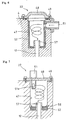
- the foreign matter remover 22 in the variable-capacity compressor 1 adopting the structure described above is disposed on the intake passage 12 formed at the rear housing 4.
- the foreign matter remover 22 includes a cylindrical bottomed space 47 formed at the rear housing 4, the upper side of which is sealed with an upper lid 48 mounted via bolts 49.
- an inflow port 51 constituting part of the intake passage 12 is connected to the space 47 on the upper side of the space 47 along a tangential direction.
- the refrigerant having flowed in through the inflow port 51 advances further into the space 47 as indicated by the arrows and moves in a swirling flow within the space 47.
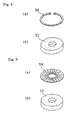
- a capturing member 52 constituted with an unwoven cloth, a nonmetal mesh or a sintered material with numerous holes formed therein is housed and held via a snap ring 56 at the bottom of the space 47. Furthermore, an outflow port 57 constituting part of the intake passage 12 is formed so as to project out at the center of the bottom of the space 47, with the upper end of the outflow port 57 projecting further out beyond the upper end of the capturing member 52 by an optimal extent.
- the refrigerant having flowed in through the inflow port 51 at the foreign matter remover 22 adopting the structure described above moves further into the space 47 in a swirling flow as indicated by the arrows.
- the foreign matter present in the refrigerant is mainly iron, aluminum, SiC and the like, and due to the difference between the specific gravity of the foreign matter and the specific gravity of the refrigerant, the foreign matter becomes separated and forced toward the outside to collide with the inner wall surface. After hitting the inner wall surface, the foreign matter precipitates down and is thus captured by the capturing member 52.
- the refrigerant, now free of foreign matter is then guided into the intake chamber 11 through the outflow port 57 at the center.
- the upper lid 48 can be opened by removing the bolts 49 to replace the capturing member 52 inside if a problem that necessitates such replacement ever occurs.
- FIG. 6 presents a variation of the capturing member 52, which assumes a cylindrical shape. Such a capturing member 52 captures the separated foreign matter with an even higher capturing rate. Since other parts of the foreign matter remover are identical to those in the previous embodiment, the same reference numerals are assigned to the identical members to preclude the necessity for a repeated explanation thereof.
- FIGS. 7 and 8 present a variation of the swirl-generating means for creating a swirling flow.
- the inflow port 51 is formed as a hole elongated along the vertical direction at the upper lid 48 so as to effectively create a swirling flow for the refrigerant supplied from the upper side in conjunction with a certain refrigerant piping layout.
- An opening 51 a of the inflow port 51 is formed at a side and by allowing the refrigerant to flow into the space 47 along a tangential direction through the opening 51a, the swirling flow advancing along the direction indicated by the arrows in FIG. 8 is created. Namely, since the refrigerant is caused to move as a swirling flow, foreign matter can be separated from the refrigerant with centrifugal force, as in the previous embodiment. It is to be noted that the inflow ports 51 allow for variations such as those shown in FIGS. 9(a), 9(b) and 9(c) .
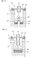
- FIGS. 10 and 11 present further variations of the swirl-generating means for creating a swirling flow of the refrigerant.
- the swirl-generating means in FIG. 10 creates a swirling flow of the refrigerant supplied from the upper side, with a spiral guide member 60 disposed to extend along the vertical direction at the center of the space 47.
- the guide member guides the refrigerant having flowed in to move as indicated by the arrows in a swirling flow and as the swirling flow advances, foreign matter can be separated with centrifugal force.
- FIG. 11 shows a swirl-generating means constituted with a spiral guide member 60 disposed to extend along the vertical direction at the center of the space 47, as in the previous example, and another guide member 62 for creating a swirling flow of the refrigerant disposed at the inner wall surface of the space 47.
- the refrigerant having flowed in is guided by the central guide member 60 and the outer guide member 62 to move in a swirling flow and foreign matter can be effectively separated from the refrigerant as it advances in the swirling flow.
- the refrigerant is let out through the upper side of the space 47 through an outflow port 57 suspended from above at the center of the space and ranging over the rear housing 4.
- the front end of the outflow port 57 reaches the lower side of the space 47.
- the refrigerant having flowed into the space 47 through the inflow port 51 moves in a swirling flow, as indicated by the arrows and while it advances in the swirling flow, foreign matter becomes separated from the refrigerant.
- the refrigerant having become free of foreign matter enters the outflow port 57 through its front end disposed near the bottom of the space, rises up through the outflow port and flows out through the upper side of the space 47.
- the capturing member 52 is held with a retainer plug 64 and thus, the retainer plug 64 only needs to be disengaged whenever the capturing member 52 needs to be replaced.
- FIGS. 13 and 14 each present an example of a separation unit that separates foreign matter from the refrigerant by causing collision of the refrigerant.
- the inflow port 51 is disposed at the upper lid 48, and the refrigerant is made to flow downward, as indicated by the arrows, through the inflow port 51. It then collides with an umbrella-shaped separation plate 63 and the impact of the collision forces foreign matter out of the refrigerant to precipitate downward and be captured by the capturing member 52. The refrigerant having become free of foreign matter then flows out through the outflow port 57.
- the inflow port 51 is disposed at the upper lid 48 and the refrigerant is made to flow downward through the inflow port 51 as indicated by the arrows.
- the refrigerant then directly collides with the capturing member 52, foreign matter is thus captured by the capturing member 52 and the refrigerant makes a U-turn to flow out through the outflow port 57.
- the same reference numerals are assigned to components in embodiment 3, 4, 5, 6, 7 and 8 that are identical to those in the first embodiment to preclude the necessity for a repeated explanation thereof.
Landscapes
- Engineering & Computer Science (AREA)
- Mechanical Engineering (AREA)
- General Engineering & Computer Science (AREA)
- Chemical & Material Sciences (AREA)
- Chemical Kinetics & Catalysis (AREA)
- Compressors, Vaccum Pumps And Other Relevant Systems (AREA)
- Compressor (AREA)
- Separating Particles In Gases By Inertia (AREA)
- Cyclones (AREA)
Claims (12)
- Kompressor (10), der mit einer Fremdstoffentfernungseinrichtung (22) ausgestattet ist, die Folgendes umfasst:einen Raum, der an einem Ansaugdurchgang des Kompressors (10) gebildet ist und eine Einströmöffnung (51) aufweist, durch die Kältemittel einströmt,eine Abscheideeinheit, die zum Abscheiden von Fremdstoffen aus dem Kältemittel eingerichtet ist, das von der Einströmöffnung in den Raum strömt,ein Einfangelement (52), das zumindest unterhalb des Raumes angeordnet ist und zum Einfangen der Fremdstoffe eingerichtet ist, die abgeschieden worden sind, undeine Ausströmöffnung (57), die an dem Raum angeordnet ist und durch die das Kältemittel aus dem Raum ausströmt,dadurch gekennzeichnet, dass das Einfangelement (52) zumindest an einer Position vorgesehen ist, an der die sich aus der Kältemittelströmung abscheidenden Fremdstoffe sich nach unten absetzen und von dem Einfangelement (52) aufgefangen werden, und wodurch das Einfangelement (52) ein Zusetzen verhindert und einen zusätzlichen Strömungswiderstand gegenüber der Kältemittelströmung verhindert.
- Kompressor, der mit einer Fremdstoffentfernungseinrichtung (22) nach Anspruch 1 ausgestattet ist, dadurch gekennzeichnet, dass die Ausströmöffnung (57) so an einer Mitte eines Bodens des Raumes angeordnet ist, dass sie von dem Boden, durch den das Kältemittel ausströmt, aufrecht hochragt.
- Kompressor, der mit einer Fremdstoffentfernungseinrichtung (22) nach Anspruch 1 oder 2 ausgestattet ist, dadurch gekennzeichnet, dass die Ausströmöffnung (57) an einer substanziellen Mitte des Raumes von oben herabhängt, was das Kältemittel so leitet, dass es durch eine Oberseite des Raumes ausströmt.
- Kompressor, der mit einer Fremdstoffentfernungseinrichtung (22) nach einem der Ansprüche 1 bis 3 ausgestattet ist, dadurch gekennzeichnet,
dass die Abscheideeinheit, die die Fremdstoffe abscheidet, mit einer Wirbel erzeugenden Einrichtung gebildet ist, um eine Wirbelströmung des Kältemittels, das eingeströmt ist, zu bewirken. - Kompressor, der mit einer Fremdstoffentfernungseinrichtung (22) nach Anspruch 4 ausgestattet ist, dadurch gekennzeichnet,
dass die Wirbel erzeugende Einrichtung eine Wirbelströmung mit einer Einströmöffnung (51) schafft, die entlang einer Tangentialrichtung mit dem Raum verbunden ist. - Kompressor, der mit einer Fremdstoffentfernungseinrichtung (22) nach Anspruch 4 ausgestattet ist, dadurch gekennzeichnet,
dass die Wirbel erzeugende Einrichtung eine Wirbelströmung durch eine Öffnung eines Einströmabschnitts schafft, der so ausgerichtet ist, dass er das Kältemittel entlang einer Tangentialrichtung in den Raum auslässt. - Kompressor, der mit einer Fremdstoffentfernungseinrichtung (22) nach Anspruch 4 ausgestattet ist, dadurch gekennzeichnet,
dass die Wirbel schaffende Einrichtung eine Wirbelströmung mit einem spiralförmigen Führungsabschnitt schafft, der in dem Raum angeordnet ist. - Kompressor, der mit einer Fremdstoffentfernungseinrichtung (22) nach einem der Ansprüche 1 bis 3 ausgestattet ist, dadurch gekennzeichnet,
dass das Einfangelement (52) aus einem nicht gewebten Stoff gebildet ist. - Kompressor, der mit einer Fremdstoffentfernungseinrichtung (22) nach einem der Ansprüche 1 bis 3 ausgestattet ist, dadurch gekennzeichnet,
dass das Einfangelement (52) aus einem nichtmetallischen Geflecht gebildet ist. - Kompressor, der mit einer Fremdstoffentfernungseinrichtung (22) nach einem der Ansprüche 1 bis 3 ausgestattet ist, dadurch gekennzeichnet,
dass das Einfangelement (52) aus einem Sintermaterial mit zahlreichen darin ausgebildeten Löchern gebildet ist. - Kompressor, der mit einer Fremdstoffentfernungseinrichtung (22) nach den Ansprüchen 1 bis 2 ausgestattet ist, dadurch gekennzeichnet,
dass ein oberes Ende der Ausströmöffnung (57) weiter nach oben über die obere Fläche des Einfangelements (52) hinaus ragt. - Kompressor, der mit einer Fremdstoffentfernungseinrichtung (22) nach einem der Ansprüche 1 bis 3 ausgestattet ist, dadurch gekennzeichnet,
dass die Abscheideeinheit, die Fremdstoffe abscheidet, ein Aufprallelement ist, das die Fremdstoffe abscheidet, indem es einen Aufprall des eintretenden Kältemittels bewirkt.
Applications Claiming Priority (2)
| Application Number | Priority Date | Filing Date | Title |
|---|---|---|---|
| JP2004223346A JP4910185B2 (ja) | 2004-07-30 | 2004-07-30 | 異物除去装置を有する圧縮機 |
| PCT/JP2005/003932 WO2006011263A1 (ja) | 2004-07-30 | 2005-03-08 | 異物除去装置を有する圧縮機 |
Publications (3)
| Publication Number | Publication Date |
|---|---|
| EP1795753A1 EP1795753A1 (de) | 2007-06-13 |
| EP1795753A4 EP1795753A4 (de) | 2012-08-22 |
| EP1795753B1 true EP1795753B1 (de) | 2015-04-29 |
Family
ID=35786019
Family Applications (1)
| Application Number | Title | Priority Date | Filing Date |
|---|---|---|---|
| EP20050720204 Ceased EP1795753B1 (de) | 2004-07-30 | 2005-03-08 | Kompressor mit vorrichtung zum entfernen von fremdstoffen |
Country Status (3)
| Country | Link |
|---|---|
| EP (1) | EP1795753B1 (de) |
| JP (1) | JP4910185B2 (de) |
| WO (1) | WO2006011263A1 (de) |
Cited By (1)
| Publication number | Priority date | Publication date | Assignee | Title |
|---|---|---|---|---|
| US9865852B2 (en) | 2015-06-25 | 2018-01-09 | Tesla, Inc. | Energy storage container with vortex separator |
Families Citing this family (8)
| Publication number | Priority date | Publication date | Assignee | Title |
|---|---|---|---|---|
| FR2981859B1 (fr) * | 2011-10-27 | 2013-11-15 | Coutier Moulage Gen Ind | Procede et dispositif pour la decantation d'huile contenue dans un flux gazeux |
| JP5860780B2 (ja) * | 2012-07-27 | 2016-02-16 | 行政院勞工委員會勞工安全衛生研究所 | 携帯式ナノ粒子サンプラ |
| CN104634014B (zh) * | 2015-02-17 | 2017-02-01 | 重庆大学 | 气液分离器及制冷系统、热泵系统 |
| WO2017086130A1 (ja) * | 2015-11-18 | 2017-05-26 | 寿産業株式会社 | 冷媒処理装置及び冷凍空調システム |
| BE1024631B9 (nl) * | 2016-10-11 | 2019-05-13 | Atlas Copco Airpower Nv | Vloeistofafscheider |
| FR3074273B1 (fr) * | 2017-11-28 | 2020-01-17 | Valeo Systemes Thermiques | Bouteille deshydratante pour un circuit de fluide refrigerant equipant un vehicule, notamment automobile. |
| JP7403219B2 (ja) * | 2018-11-22 | 2023-12-22 | 三菱電機株式会社 | 加熱調理器 |
| CN112212548B (zh) * | 2020-10-30 | 2024-06-14 | 安徽同速环保科技有限公司 | 一种制冷剂两相混合流进液均布装置及其应用 |
Family Cites Families (15)
| Publication number | Priority date | Publication date | Assignee | Title |
|---|---|---|---|---|
| CS160281B1 (de) * | 1971-12-22 | 1975-03-28 | ||
| JPS5125107U (de) * | 1974-08-14 | 1976-02-24 | ||
| JPS55163489U (de) * | 1979-05-11 | 1980-11-25 | ||
| JPS63136718A (ja) * | 1986-11-28 | 1988-06-08 | Hitachi Ltd | Pll回路 |
| JPH03114585A (ja) * | 1989-09-29 | 1991-05-15 | Sumitomo Jukikai Envirotec Kk | 汚泥処理法 |
| JPH03114585U (de) * | 1990-03-09 | 1991-11-25 | ||
| JP3662301B2 (ja) * | 1995-07-05 | 2005-06-22 | 有光工業株式会社 | ポンプ装置用吸水ストレーナ |
| JPH09222083A (ja) * | 1996-02-16 | 1997-08-26 | Matsushita Electric Ind Co Ltd | 冷凍サイクルと圧縮機 |
| JP3546736B2 (ja) * | 1999-01-21 | 2004-07-28 | 三菱電機株式会社 | 冷凍装置 |
| JP2000303956A (ja) * | 1999-04-20 | 2000-10-31 | Toyota Autom Loom Works Ltd | 圧縮機における液圧縮防止構造 |
| JP3721933B2 (ja) * | 2000-04-17 | 2005-11-30 | 株式会社デンソー | 圧縮機 |
| JP4502347B2 (ja) * | 2000-11-06 | 2010-07-14 | 日立アプライアンス株式会社 | スクリュー圧縮機 |
| JP3901453B2 (ja) * | 2001-01-23 | 2007-04-04 | 株式会社栗本鐵工所 | 飛灰除去装置 |
| JP2002263430A (ja) * | 2001-03-13 | 2002-09-17 | Toyota Industries Corp | 流体回路の異物除去構造及び圧縮機 |
| US6764593B1 (en) * | 2002-11-06 | 2004-07-20 | Scot M. Pace | Automobile air conditioning refrigerant filter |
-
2004
- 2004-07-30 JP JP2004223346A patent/JP4910185B2/ja not_active Expired - Fee Related
-
2005
- 2005-03-08 EP EP20050720204 patent/EP1795753B1/de not_active Ceased
- 2005-03-08 WO PCT/JP2005/003932 patent/WO2006011263A1/ja not_active Ceased
Cited By (1)
| Publication number | Priority date | Publication date | Assignee | Title |
|---|---|---|---|---|
| US9865852B2 (en) | 2015-06-25 | 2018-01-09 | Tesla, Inc. | Energy storage container with vortex separator |
Also Published As
| Publication number | Publication date |
|---|---|
| EP1795753A4 (de) | 2012-08-22 |
| JP4910185B2 (ja) | 2012-04-04 |
| EP1795753A1 (de) | 2007-06-13 |
| JP2006037932A (ja) | 2006-02-09 |
| WO2006011263A1 (ja) | 2006-02-02 |
Similar Documents
| Publication | Publication Date | Title |
|---|---|---|
| EP1795753B1 (de) | Kompressor mit vorrichtung zum entfernen von fremdstoffen | |
| JP5226801B2 (ja) | ガス−オイル分離のためのサイクロン分離装置 | |
| EP2025936B1 (de) | Verdichter | |
| US6475256B2 (en) | Cyclone type gas-liquid separator | |
| US8449767B2 (en) | Oil reservoir comprising an oil filter | |
| CN203068891U (zh) | 立式油分离器 | |
| JPH0760036B2 (ja) | オイルセパレータ | |
| CN108026805B (zh) | 用于驱动漏气的泵装置 | |
| KR100299753B1 (ko) | 스크롤장치 | |
| EP2664386B1 (de) | Zentrifugalabscheider | |
| CN101990467A (zh) | 用于内燃机的曲轴箱通风的分离器 | |
| JPH0857234A (ja) | 空気から油エーロゾルを分離するための装置 | |
| CN101472623A (zh) | 在净化侧的流动通道中的具有止回阀的液体过滤器 | |
| WO2015029845A1 (ja) | オイルセパレータおよびそれを備えた圧縮機 | |
| EP3560403B1 (de) | Staubsammlungsvorrichtung mit verwendung von multi-zyklon-staubfilterung | |
| JP4103047B2 (ja) | オイルセパレーター及びpcvシステム | |
| JP5018696B2 (ja) | オイルセパレータ及びオイルセパレータを備える冷媒圧縮機 | |
| CN103282661A (zh) | 制冷剂压缩机 | |
| JP2005120972A (ja) | 往復式可変容量型圧縮機 | |
| KR100847861B1 (ko) | 자동차용 오일 세퍼레이터 | |
| JP3805500B2 (ja) | 油冷式圧縮機の油分離回収器 | |
| JP2538453Y2 (ja) | 油冷式スクリュ圧縮機 | |
| CN114109819A (zh) | 压缩机排气油分结构、涡旋压缩机 | |
| JP4880127B2 (ja) | キャンドモータポンプの異物除去チャンバ | |
| CN102232002A (zh) | 可更换过滤器元件 |
Legal Events
| Date | Code | Title | Description |
|---|---|---|---|
| PUAI | Public reference made under article 153(3) epc to a published international application that has entered the european phase |
Free format text: ORIGINAL CODE: 0009012 |
|
| 17P | Request for examination filed |
Effective date: 20070228 |
|
| AK | Designated contracting states |
Kind code of ref document: A1 Designated state(s): DE FR |
|
| DAX | Request for extension of the european patent (deleted) | ||
| RBV | Designated contracting states (corrected) |
Designated state(s): DE FR |
|
| A4 | Supplementary search report drawn up and despatched |
Effective date: 20120723 |
|
| RIC1 | Information provided on ipc code assigned before grant |
Ipc: F04B 39/16 20060101AFI20120717BHEP Ipc: B04C 9/00 20060101ALI20120717BHEP Ipc: B04C 5/06 20060101ALI20120717BHEP Ipc: B01D 45/16 20060101ALI20120717BHEP Ipc: B04C 5/187 20060101ALI20120717BHEP Ipc: B04C 3/06 20060101ALI20120717BHEP Ipc: F04B 27/10 20060101ALI20120717BHEP |
|
| RIC1 | Information provided on ipc code assigned before grant |
Ipc: F25B 43/00 20060101ALI20140228BHEP Ipc: F04B 27/10 20060101ALI20140228BHEP Ipc: F04B 39/16 20060101AFI20140228BHEP Ipc: B04C 3/06 20060101ALI20140228BHEP Ipc: B04C 3/00 20060101ALI20140228BHEP Ipc: B04C 5/06 20060101ALI20140228BHEP Ipc: B01D 45/16 20060101ALI20140228BHEP Ipc: B04C 9/00 20060101ALI20140228BHEP Ipc: B04C 5/187 20060101ALI20140228BHEP |
|
| RAP1 | Party data changed (applicant data changed or rights of an application transferred) |
Owner name: VALEO JAPAN CO., LTD. |
|
| GRAP | Despatch of communication of intention to grant a patent |
Free format text: ORIGINAL CODE: EPIDOSNIGR1 |
|
| INTG | Intention to grant announced |
Effective date: 20141118 |
|
| GRAS | Grant fee paid |
Free format text: ORIGINAL CODE: EPIDOSNIGR3 |
|
| GRAA | (expected) grant |
Free format text: ORIGINAL CODE: 0009210 |
|
| AK | Designated contracting states |
Kind code of ref document: B1 Designated state(s): DE FR |
|
| REG | Reference to a national code |
Ref country code: DE Ref legal event code: R096 Ref document number: 602005046442 Country of ref document: DE Effective date: 20150611 |
|
| REG | Reference to a national code |
Ref country code: DE Ref legal event code: R097 Ref document number: 602005046442 Country of ref document: DE |
|
| REG | Reference to a national code |
Ref country code: FR Ref legal event code: PLFP Year of fee payment: 12 |
|
| PLBE | No opposition filed within time limit |
Free format text: ORIGINAL CODE: 0009261 |
|
| STAA | Information on the status of an ep patent application or granted ep patent |
Free format text: STATUS: NO OPPOSITION FILED WITHIN TIME LIMIT |
|
| 26N | No opposition filed |
Effective date: 20160201 |
|
| REG | Reference to a national code |
Ref country code: FR Ref legal event code: PLFP Year of fee payment: 13 |
|
| REG | Reference to a national code |
Ref country code: FR Ref legal event code: PLFP Year of fee payment: 14 |
|
| PGFP | Annual fee paid to national office [announced via postgrant information from national office to epo] |
Ref country code: DE Payment date: 20180220 Year of fee payment: 14 |
|
| PGFP | Annual fee paid to national office [announced via postgrant information from national office to epo] |
Ref country code: FR Payment date: 20180223 Year of fee payment: 14 |
|
| REG | Reference to a national code |
Ref country code: DE Ref legal event code: R119 Ref document number: 602005046442 Country of ref document: DE |
|
| PG25 | Lapsed in a contracting state [announced via postgrant information from national office to epo] |
Ref country code: DE Free format text: LAPSE BECAUSE OF NON-PAYMENT OF DUE FEES Effective date: 20191001 |
|
| PG25 | Lapsed in a contracting state [announced via postgrant information from national office to epo] |
Ref country code: FR Free format text: LAPSE BECAUSE OF NON-PAYMENT OF DUE FEES Effective date: 20190331 |