EP1795440B1 - Schutzmantel zum Schutz der Antriebskette eines Fahrrades - Google Patents
Schutzmantel zum Schutz der Antriebskette eines Fahrrades Download PDFInfo
- Publication number
- EP1795440B1 EP1795440B1 EP07001786A EP07001786A EP1795440B1 EP 1795440 B1 EP1795440 B1 EP 1795440B1 EP 07001786 A EP07001786 A EP 07001786A EP 07001786 A EP07001786 A EP 07001786A EP 1795440 B1 EP1795440 B1 EP 1795440B1
- Authority
- EP
- European Patent Office
- Prior art keywords
- protective covering
- drive
- drive sprocket
- chain
- sprocket
- Prior art date
- Legal status (The legal status is an assumption and is not a legal conclusion. Google has not performed a legal analysis and makes no representation as to the accuracy of the status listed.)
- Expired - Lifetime
Links
- 230000001681 protective effect Effects 0.000 title claims abstract description 71
- 239000000463 material Substances 0.000 claims description 4
- 239000004033 plastic Substances 0.000 claims description 4
- 229920003023 plastic Polymers 0.000 claims description 4
- 238000007789 sealing Methods 0.000 claims description 3
- 239000002783 friction material Substances 0.000 claims description 2
- 230000002035 prolonged effect Effects 0.000 claims 2
- 230000000284 resting effect Effects 0.000 claims 1
- 230000000717 retained effect Effects 0.000 claims 1
- 238000005253 cladding Methods 0.000 description 3
- 238000011109 contamination Methods 0.000 description 3
- 230000001012 protector Effects 0.000 description 3
- 238000010276 construction Methods 0.000 description 2
- 230000000694 effects Effects 0.000 description 2
- 229910001651 emery Inorganic materials 0.000 description 2
- 239000004698 Polyethylene Substances 0.000 description 1
- 239000004519 grease Substances 0.000 description 1
- 238000009434 installation Methods 0.000 description 1
- 238000004519 manufacturing process Methods 0.000 description 1
- 239000002184 metal Substances 0.000 description 1
- -1 polyethylene Polymers 0.000 description 1
- 229920000573 polyethylene Polymers 0.000 description 1
Images





Classifications
-
- B—PERFORMING OPERATIONS; TRANSPORTING
- B62—LAND VEHICLES FOR TRAVELLING OTHERWISE THAN ON RAILS
- B62J—CYCLE SADDLES OR SEATS; AUXILIARY DEVICES OR ACCESSORIES SPECIALLY ADAPTED TO CYCLES AND NOT OTHERWISE PROVIDED FOR, e.g. ARTICLE CARRIERS OR CYCLE PROTECTORS
- B62J13/00—Guards for chain, chain drive or equivalent drive, e.g. belt drive
-
- B—PERFORMING OPERATIONS; TRANSPORTING
- B62—LAND VEHICLES FOR TRAVELLING OTHERWISE THAN ON RAILS
- B62J—CYCLE SADDLES OR SEATS; AUXILIARY DEVICES OR ACCESSORIES SPECIALLY ADAPTED TO CYCLES AND NOT OTHERWISE PROVIDED FOR, e.g. ARTICLE CARRIERS OR CYCLE PROTECTORS
- B62J13/00—Guards for chain, chain drive or equivalent drive, e.g. belt drive
- B62J13/04—Guards for chain, chain drive or equivalent drive, e.g. belt drive completely enclosing the chain drive or the like
Definitions
- the present invention relates to a protective sheath attached to a drive pinion of a bicycle for protecting the area of a drive chain surrounding the drive pinion. From the DE 3629463 a chain guard with the features of the preamble of claim 1 is known.
- An unprotected drive chain of a bicycle is exposed to the risk of contamination while driving.
- the road dirt flung up by the wheels of a bicycle adheres to the greased or oiled surface of the chain links and mixes there with the oil or grease to a kind of emery paste and is finally driven by the teeth of the drive pinion as well as the output pinion in the joints of the chain links.
- the emery effect weakens the joints of a bicycle chain in such a way that the service life of a drive chain is drastically reduced.
- chain guards consist of a lining for the chainring of the bottom bracket, which is hereinafter referred to as a drive pinion, a lining for the output pinion of the rear wheel and two protective tubes, which are connected to the panels and extending each of the drive pinion to the output pinion area of the Protect drive chain.
- the panels themselves are each composed of two housing halves.
- Such chain guards thus represent a complex and expensive construction, require a high assembly cost and must be additionally set in the drive pinion by means of a suitable holding device on the bicycle frame.
- the high weight Of course, such a chain protector also has a negative effect on the overall weight of a bicycle equipped with it.
- Another disadvantage of such chain guards is that provided in the bottom bracket trim panel is particularly impact sensitive from the pedal side. A blow to the fairing may bend the chain guard support so that the fairing is pressed against the drive chain, resulting in a severe disturbance of the driving operation.
- the object of the invention is to show a protective jacket of the generic type, which is easy to manufacture and assemble, ensures effective protection of the drive chain on the drive pinion and has a low weight.
- a protective jacket 3 is provided to protect a drive pinion 1 and this drive pinion 1 partially wrap around drive chain 2, which is considered to be stationary relative to the drive pinion 1 and the drive chain 2.
- the protective jacket 3 which is particularly the FIG. 3 very clearly shows, circular.
- the protective jacket 3 but also have other cross-sectional shapes.
- the protective jacket 3 is provided along its inner surface line with an opening 4 through which the drive pinion 1 passes into the interior of the protective jacket 3.
- the protective jacket 3 thus protects the area of the drive pinion 1 enclosed by the drive chain 2 and, of course, the area of the drive chain 2 located there against contamination.
- the protective jacket 3 is self-holding and centering partly on the drive pinion 1 and partly on the drive chain 2.
- the protective jacket 3 can be extended in the direction of the chain line 2 a in the direction of a rear wheel of a bicycle relative to the illustrated embodiment and correspondingly enclose the largest area of the drive chain 2 in a protective manner.
- an additional cover 5 is provided.
- This cladding 5 adjoins both the upper and the lower region of the protective jacket 3.
- the cladding 5 has, in the region of its surface line facing the drive pinion 1, a groove 5a, which is adapted in terms of its width to the thickness of the drive pinion 1.
- the panel 5 is thus on the drive pinion 1 and is centered by this.
- the panel 5 may be advantageously secured by connection to the protective jacket 3.
- the cladding 5 can also be less elegantly fixed to the bicycle frame.
- the mounting of the protective jacket 3 can be done in various ways depending on the construction of the protective jacket 3.
- the protective jacket 3 is made, for example, of a stiff material, it must be pushed onto the drive pinion 1 before the drive chain 2 is mounted.
- the still open drive chain 2 is passed through one of the ends of the protective jacket 3, taken up by the drive pinion 1 and led out by turning the drive pinion 1 from the other end of the protective jacket 3 again.
- the drive chain 2 may already be mounted on the drive pinion 1 and by spreading the opening 4, the protective jacket 3 via the drive chain 2 on the drive pinion 1 are pushed.
- the protective jacket 3 consists of a front portion 3a and a rear end portion 3b.
- the front portion 3a of the protective jacket 3 is provided to protect the drive pinion 1 and to protect the over the drive pinion 1 also extending portions of a drive chain.
- This front portion 3a consists of split in the longitudinal direction of the chain, identical halves, which are connected to each other by clamping.
- the rear end portion 3b of the protective jacket 3 consists of two additional parts 3c and 3d, as the FIGS. 10 to 12 can be easily removed.
- the arcuately shaped additional part 3c serves to protect a rear output pinion in the area looped by a drive chain 2.
- the additional additional part 3d which is preferably latchingly connectable with the additional part 3c, serves to cover the region of a rear driven pinion not looped by the drive chain 2.
- the additional part 3c is provided with locking recesses 3e, in which latch cam 3f engage in the assembled state. This results in a positive connection between the two additional parts 3c and 3d.
- the two additional parts 3c and 3d are designed so that they form receiving channels 3g in the assembled state in their the front portion 3a of the protective sheath 3 facing end portions whose light cross section corresponds approximately to the outer cross section of the rear ends of the front portion 3a of the protective jacket 3.
- the front portion 3a of the protective jacket 3 can be inserted with its rear ends in these receiving channels 3g and 3c and 3d finally connected to the rear additional parts.
- a latching connection should also be provided in order to allow easy disassembly of these parts if necessary.
- the rear ends of the front portion 3a of the protective jacket 3 can be provided with resiliently molded sealing tabs 3h, which can then abut sealingly against corresponding inner walls of the receiving channels 3g.
- the protective jacket 3 consists of a total of a few, easily assembled items, which are preferably made of a plastic.
- the entire protective jacket 3 is held and carried both by the drive pinion and the output pinion and in part by the drive chain.
- the protective jacket 3 should therefore be made of a plastic, which results in a particularly low-friction material pairing with the metal parts (drive pinion, output pinion, drive chain).
Landscapes
- Engineering & Computer Science (AREA)
- Mechanical Engineering (AREA)
- Devices For Conveying Motion By Means Of Endless Flexible Members (AREA)
- Gears, Cams (AREA)
- General Details Of Gearings (AREA)
- Automatic Cycles, And Cycles In General (AREA)
- Traffic Control Systems (AREA)
- Steering Devices For Bicycles And Motorcycles (AREA)
- Ropes Or Cables (AREA)
Description
- Die vorliegende Erfindung betrifft einen an einem Antriebsritzel eines Fahrrades angebrachten Schutzmantel zum Schutz des das Antriebsritzel umschließenden Bereiches einer Antriebskette. Aus der
DE 3629463 ist ein Kettenschutzmantel mit den Merkmalen des Oberbegriffes des Anspruchs 1 bekannt. - Eine ungeschützte Antriebskette eines Fahrrades ist während der Fahrt der Gefahr der Verschmutzung ausgesetzt. Der von den Laufrädern eines Fahrrades hochgeschleuderte Fahrbahnschmutz haftet an der gefetteten oder geölten Oberfläche der Kettenglieder und vermischt sich dort mit dem Öl oder Fett zu einer Art Schmirgelpaste und wird schließlich von den Zähnen des Antriebsritzels wie auch das Abtriebsritzels in die Gelenke der Kettenglieder getrieben. Durch die Schmirgelwirkung werden die Gelenke einer Fahrradkette derart geschwächt, dass sich die Lebensdauer einer Antriebskette drastisch verringert.
- Antriebsketten bei Fahrrädern mit Nabengangschaltungen, die im Gegensatz zu Kettengangschaltungen ihre Kettenlinie beim Gangwechsel nicht ändern, also immer auf denselben Ritzeln bleiben, lassen sich relativ gut durch einen Kettenschutz vor Verschmutzung schützen.
- Solche Kettenschützer gibt es bereits in unterschiedlichsten Ausführungen.
- Die bislang fortschrittlichsten unter den bekannten Kettenschützern schützen die Antriebskette vollständig umlaufend. Diese Kettenschützer bestehen aus einer Verkleidung für das Kettenblatt des Tretlagers, welches im folgenden als Antriebsritzel bezeichnet wird, einer Verkleidung für das Abtriebsritzel des hinteren Laufrades und aus zwei Schutzrohren, welche mit den Verkleidungen verbunden sind und die den jeweils vom Antriebsritzel zum Abtriebsritzel verlaufenden Bereich der Antriebskette schützen. Die Verkleidungen selbst sind jeweils aus zwei Gehäusehälften zusammengesetzt. Derartige Kettenschützer stellen also eine aufwendige und teure Konstruktion dar, bedingen einen hohe Montageaufwand und müssen zusätzlich im Bereich des Antriebsritzels mittels einer geeigneten Haltevorrichtung am Fahrradrahmen festgelegt werden. Das hohe Gewicht eines derartigen Kettenschützers wirkt sich selbstverständlich auch negativ auf das Gesamtgewicht eines damit ausgestatteten Fahrrades aus.
- Ein weiterer Nachteil solcher Kettenschützer besteht darin, dass die im Bereich des Tretlagers vorgesehene Verkleidung besonders von der Pedalseite her schlagempfindlich ist. Ein Schlag auf die Verkleidung kann die Haltevorrichtung des Kettenschützers unter Umständen so verbiegen, dass die Verkleidung gegen Antriebskette angepresst wird, was zu einer starken Störung des Fahrbetriebes führt.
- Aufgabe der Erfindung ist es, einen Schutzmantel der gattungsgemäßen Art aufzuzeigen, der einfach herstellbar und montierbar ist, einen wirksamen Schutz der Antriebskette am Antriebsritzel gewährleistet und ein geringes Gewicht aufweist.
- Diese Aufgabe wird durch die Merkmale des kennzeichnenden Teils des Anspruches 1 gelöst.
- Weitere Merkmale der Erfindung sind Gegenstand weiterer Unteransprüche.
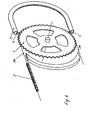
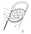
- Ausführungsbeispiele der Erfindung sind in den beigefügten Zeichnungen dargestellt und werden im folgenden näher beschrieben. Es zeigen:
- Fig. 1
- eine Ansicht eines erfindungsgemäßen Schutzmantels im Bereich des vorderen Antriebsritzels eines Fahrrades montiert;
- Fig. 2
- einen Teilschnitt nach der Linie II-II in
Figur 1 ; - Fig. 3
- einen Teilschnitt nach der Linie III-III in
Figur 1 ; - Fig. 4
- eine perspektivische Sprengbilddarstellung des Schutzmantels nach
Figur 1 ; - Fig. 5
- eine der
Figur 4 entsprechende Sprengbilddarstellung in einer anderen Perspektiv-Ansicht; - Fig. 6
- eine perspektivische Darstellung des Schutzmantels im montierten Zustand;
- Fig. 7
- eine perspektivische Darstellung eines Schutzmantels nach einem weiteren Ausführungsbeispiel der Erfindung;
- Fig. 8
- eine Ansicht des Schutzmantels gemäss
Figur 7 ; - Fig. 9
- eine Ansicht in Richtung des Pfeiles IX in
Figur 8 ; - Fig. 10
- eine perspektivische Sprengbilddarstellung des hinteren Teilbereiches des Schutzmantels nach den
Figuren 7 bis 9 ; - Fig. 11
- eine perspektivische Darstellung des hinteren Bereiches des Schutzmantels gemäss
Figur 10 im montierten Zustand, und - Fig. 12
- eine Ansicht des hinteren Bereiches des Schutzmantels kurz vor der Verbindung mit dem vorderen Bereich des Schutzmantels.
- Bei dem in den
Figuren 1 bis 6 gezeigten Ausführungsbeispiel der Erfindung ist zum Schutz eines Antriebsritzels 1 sowie einer dieses Antriebsritzel 1 teilweise umschlingenden Antriebskette 2 ein Schutzmantel 3 vorgesehen, welcher relativ zum Antriebsritzel 1 sowie zur Antriebskette 2 als stationär anzusehen ist. - Im dargestellten Ausführungsbeispiel ist der Schutzmantel 3, was besonders die
Figur 3 sehr deutlich zeigt, kreisrund ausgebildet. Selbstverständlich kann der Schutzmantel 3 aber auch andere Querschnittsformen aufweisen. - Wie insbesondere aus
Figur 4 hervorgeht, ist der Schutzmantel 3 längs seiner inneren Mantellinie mit einer Öffnung 4 versehen, durch welche das Antriebsritzel 1 in das Innere des Schutzmantels 3 hindurchtritt. - Durch den Schutzmantel 3 ist somit der von der Antriebskette 2 umschlossene Bereich des Antriebsritzel 1 sowie selbstverständlich der dort liegende Bereich der Antriebskette 2 gegen Verschmutzung geschützt. Der Schutzmantel 3 liegt dabei selbsthaltend und zentrierend teils am Antriebsritzel 1 und teils an der Antriebskette 2 an.
- Der Schutzmantel 3 kann gegenüber der dargestellten Ausführungsform in Richtung der Kettenlinie 2a in Richtung eines Hinterrades eines Fahrrades verlängert sein und entsprechend den größten Bereich der Antriebskette 2 schützend umschließen.
- Als zusätzlicher Schutz für den Bereich des Antriebsritzels 1, der außerhalb des Umschlingungsbereiches der Antriebskette 2 liegt, ist eine zusätzliche Verkleidung 5 vorgesehen. Diese Verkleidung 5 schließt sich sowohl an den oberen wie auch den unteren Bereich des Schutzmantels 3 an. Die Verkleidung 5 weist im Bereich ihrer dem Antriebsritzel 1 zugewandten Mantellinie eine Nut 5a auf, die hinsichtlich ihrer Breite der Stärke des Antriebsritzels 1 angepasst ist. Die Verkleidung 5 liegt somit am Antriebsritzel 1 an und wird durch dieses zentriert.
- Die Verkleidung 5 kann vorteilhafterweise durch Verbindung mit dem Schutzmantel 3 gesichert sein.
- Weniger elegant kann die Verkleidung 5 aber auch am Fahrradrahmen fixiert werden.
- Die Montage des Schutzmantels 3 kann je nach Konstruktion des Schutzmantels 3 auf verschiedene Weisen erfolgen.
- Besteht der Schutzmantel 3 beispielsweise aus einem steifen Material, so muss er vor der Montage der Antriebskette 2 auf das Antriebsritzel 1 aufgeschoben werden.
- Danach wird die noch offene Antriebskette 2 durch eines der Enden des Schutzmantels 3 hindurchgeführt, vom Antriebsritzel 1 aufgenommen und durch Drehen des Antriebsritzels 1 aus dem anderen Ende des Schutzmantels 3 wieder herausgeführt.
- Besteht der Schutzmantel 3 aus einem weichen oder biegsamen Material, zum Beispiel aus Weich-PVC, Polyethylen oder dergleichen, so kann die Antriebskette 2 bereits am Antriebsritzel 1 montiert sein und durch Aufspreizen der Öffnung 4 kann der Schutzmantel 3 über die Antriebskette 2 auf das Antriebsritzel 1 geschoben werden.
- Zur noch einfacheren Montage des Schutzmantels 3 kann dieser aber auch geteilt angefertigt und am Antriebsritzel 1 über die Antriebskette 2 zusammengebaut werden.
- In den
Figuren 7 bis 12 ist ein Ausführungsbeispiel der Erfindung gezeigt, bei dem der Schutzmantel 3 aus einem vorderen Bereich 3a und einem hinteren Endbereich 3b besteht. Der vordere Bereich 3a des Schutzmantels 3 ist dabei zum Schutz des Antriebsritzels 1 und zum Schutz der über das Antriebsritzel 1 hinaus verlaufenden Abschnitte einer Antriebskette vorgesehen. Dieser vordere Bereich 3a besteht aus in Längsrichtung der Kette geteilten, baugleichen Hälften, die klemmend miteinander verbunden sind. - Der hintere Endbereich 3b des Schutzmantels 3 besteht aus zwei Zusatzteilen 3c und 3d, wie sich den
Figuren 10 bis 12 ohne weiteres entnehmen lässt. - Dabei dient das bogenförmig ausgebildete Zusatzteil 3c zum Schutz eines hinteren Abtriebsritzels in dem von einer Antriebskette 2 umschlungenen Bereich. Das weitere Zusatzteil 3d, welches mit dem Zusatzteil 3c vorzugsweise rastend verbindbar ist, dient zur Überdeckung des nicht von der Antriebskette 2 umschlungenen Bereiches eines hinteren Abtriebsritzels.
- Wie die
Figuren 10 und11 deutlich zeigen, ist das Zusatzteil 3c mit Rastaussparungen 3e versehen, in welche im montierten Zustand Rastnocken 3f einrasten. Dadurch ergibt sich eine formschlüssige Verbindung zwischen den beiden Zusatzteilen 3c und 3d. - Die beiden Zusatzteile 3c und 3d sind so gestaltet, dass sie im zusammengebauten Zustand in ihren dem vorderen Bereich 3a des Schutzmantels 3 zugewandten Endbereichen Aufnahmekanäle 3g bilden, deren lichter Querschnitt etwa dem äußeren Querschnitt der hinteren Enden des vorderen Bereiches 3a des Schutzmantels 3 entspricht. Damit kann der vordere Bereich 3a des Schutzmantels 3 mit seinen hinteren Enden in diese Aufnahmekanäle 3g eingeschoben und mit den hinteren Zusatzteilen 3c und 3d abschließend verbunden werden. Vorzugsweise ist auch hier eine Rastverbindung vorzusehen, um bei Bedarf eine leichte Demontage dieser Teile zu ermöglichen.
- Zu Dichtzwecken können die hinteren Enden des vorderen Bereiches 3a des Schutzmantels 3 mit federnd angeformten Dichtlappen 3h ausgestattet sein, welche dann an entsprechenden Innenwandungen der Aufnahmekanäle 3g abdichtend anliegen können.
- Beim Ausführungsbeispiel gemäss den
Figuren 7 bis 12 wird also eine vollständige Abdeckung sowohl einer Antriebskette sowie des Antriebsritzels und das Abtriebsritzels eines Fahrrades erreicht. Dabei besteht der Schutzmantel 3 insgesamt aus wenigen, leicht montierbaren Einzelteilen, die vorzugsweise aus einem Kunststoff hergestellt sind. Der gesamte Schutzmantel 3 wird dabei sowohl vom Antriebsritzel wie auch vom Abtriebsritzel und zum Teil von der Antriebskette gehalten und getragen. Vorteilhafterweise sollte der Schutzmantel 3 deshalb aus einem Kunststoff gefertigt sein, der mit den Metallteilen (Antriebsritzel, Abtriebsritzel, Antriebskette) eine besonders reibungsarme Werkstoffpaarung ergibt.
Claims (13)
- An einem Antriebsritzel (1) eines Fahrrades anbringbar ausgestalteter, stationärer Schutzmantel (3), durch den der das Antriebsritzel (1) umschließende, zu schützende Bereich einer Antriebskette aufnehmbar und überdeckbar ist und der mit einer im montierten Zustand vom Antriebsritzel (1) durchtretenen, längs einer inneren Mantellinie des Schutzmantels (3) verlaufenden Öffnung (4) versehen ist, wobei der Schutzmantel (3) im montierten Zustand selbsthaltend auf der Antriebskette (2) gehalten und zentriert ist, dadurch gekennzeichnet, dass der Schutzmantel (3) im montierten Zustand teils auf der Antriebskette (2) und teils am Antriebsritzel (3) anliegend gehalten und zentriert ist.
- Schutzmantel nach Anspruch 1, dadurch gekennzeichnet, dass der Schutzmantel (3) in der Mittelebene des Antriebsritzels (1) geteilt und die beiden Schutzmantelhälften, von den einander gegenüberliegenden Seiten des Antriebsritzels (1) ausgehend, zusammengesetzt sind.
- Schutzmantel nach Anspruch 1 oder 2, dadurch gekennzeichnet, dass der Schutzmantel (3) über das Antriebsritzel (1) hinausgehend verlängert ist und somit den oberen wie auch den unteren Trum der Antriebskette (2) schützend einschließt.
- Schutzmantel nach einem der vorhergehenden Ansprüche, dadurch gekennzeichnet, dass der außerhalb des Umschlingungsbereiches der Antriebskette (2) liegende Sektor des Antriebsritzels (1) durch eine mantelartige Verkleidung (5) überdeckt ist.
- Schutzmantel nach Anspruch 4, dadurch gekennzeichnet, dass die Verkleidung (5) mit dem Schutzmantel (3) verbunden oder einstückig mit diesem hergestellt ist.
- Schutzmantel nach Anspruch 4 oder 5, dadurch gekennzeichnet, dass die Verkleidung (5) im montierten Zustand am Antriebsritzel (1) anliegt und durch dieses zentriert ist.
- Schutzmantel nach einem der Ansprüche 4 bis 6 dadurch gekennzeichnet, dass die Verkleidung (5) im Bereich ihrer dem Antriebsritzel (1) zugewandten Mantellinie eine Nut (5a) mit einer an die Stärke des Antriebsritzels (1) angepasste Breite aufweist.
- Schutzmantel nach einem der vorhergehenden Ansprüche, dadurch gekennzeichnet, dass der Schutzmantel (3) im Bereich des hinterradseitigen Abtriebsritzels durch ansteckbare Zusatzteile (3c, 3d) verlängert ist, wobei eines der Zusatzteile (3c) das hintere Abtriebsritzel in dem von der Antriebskette (2) umschlungenen Bereich umhüllt und das andere Zusatzteil (3d) den übrigen Bereich des hinteren Abtriebsritzels überdeckt.
- Schutzmantel nach Anspruch 8, dadurch gekennzeichnet, dass die beiden Zusatzteile (3c, 3d) in ihren dem vorderen Bereich (3a) des Schutzmantels (3) zugewandten Enden Aufnahmekanäle (3g) zur Aufnahme der besagten Enden des vorderen Bereiches (3a) des Schutzmantels (3) bilden.
- Schutzmantel nach Anspruch 9, dadurch gekennzeichnet, dass die in die Aufnahmekanäle (3g) eingeführten Enden des vorderen Bereiches (3a) des Schutzmantels (3) mit federnden Dichtlappen (3h) ausgestattet sind, die sich im montierten Zustand an entsprechenden Innenwandungen der Aufnahmekanäle (3g) dichtend anlegen.
- Schutzmantel nach einem der vorhergehenden Ansprüche, dadurch gekennzeichnet, dass die beiden Zusatzteile (3c, 3d) rastend miteinander verbunden sind.
- Schutzmantel nach einem der vorhergehenden Ansprüche, dadurch gekennzeichnet, dass die hinteren Enden des vorderen Bereiches (3a) des Schutzmantels (3) innerhalb der Aufnahmekanäle (3g) rastend festgelegt sind.
- Schutzmantel nach einem oder mehreren der vorhergehenden Ansprüche, dadurch gekennzeichnet, dass der Schutzmantel (3) aus Kunststoff gefertigt ist, bevorzugt aus einen Kunststoff, der mit der Antriebskette (2) und/oder dem Antriebsritzel (1) und dem Abtriebsritzel eine besonders reibungsarme Werkstoffpaarung ergibt.
Priority Applications (2)
| Application Number | Priority Date | Filing Date | Title |
|---|---|---|---|
| DE502004008299T DE502004008299D1 (de) | 2004-08-06 | 2004-08-06 | Schutzmantel zum Schutz der Antriebskette eines Fahrrades |
| PL07001786T PL1795440T3 (pl) | 2004-08-06 | 2004-08-06 | Osłona do zabezpieczenia łańcucha napędowego roweru |
Applications Claiming Priority (1)
| Application Number | Priority Date | Filing Date | Title |
|---|---|---|---|
| EP04018665A EP1623916B1 (de) | 2004-08-06 | 2004-08-06 | Schutzmantel zum Schutz der Antriebskette eines Fahrrades |
Related Parent Applications (1)
| Application Number | Title | Priority Date | Filing Date |
|---|---|---|---|
| EP04018665A Division EP1623916B1 (de) | 2004-08-06 | 2004-08-06 | Schutzmantel zum Schutz der Antriebskette eines Fahrrades |
Publications (3)
| Publication Number | Publication Date |
|---|---|
| EP1795440A2 EP1795440A2 (de) | 2007-06-13 |
| EP1795440A3 EP1795440A3 (de) | 2007-08-01 |
| EP1795440B1 true EP1795440B1 (de) | 2008-10-15 |
Family
ID=34926078
Family Applications (2)
| Application Number | Title | Priority Date | Filing Date |
|---|---|---|---|
| EP04018665A Expired - Lifetime EP1623916B1 (de) | 2004-08-06 | 2004-08-06 | Schutzmantel zum Schutz der Antriebskette eines Fahrrades |
| EP07001786A Expired - Lifetime EP1795440B1 (de) | 2004-08-06 | 2004-08-06 | Schutzmantel zum Schutz der Antriebskette eines Fahrrades |
Family Applications Before (1)
| Application Number | Title | Priority Date | Filing Date |
|---|---|---|---|
| EP04018665A Expired - Lifetime EP1623916B1 (de) | 2004-08-06 | 2004-08-06 | Schutzmantel zum Schutz der Antriebskette eines Fahrrades |
Country Status (5)
| Country | Link |
|---|---|
| EP (2) | EP1623916B1 (de) |
| AT (2) | ATE411214T1 (de) |
| DE (2) | DE502004008299D1 (de) |
| DK (2) | DK1623916T3 (de) |
| PL (2) | PL1795440T3 (de) |
Families Citing this family (10)
| Publication number | Priority date | Publication date | Assignee | Title |
|---|---|---|---|---|
| DE102007028271A1 (de) | 2007-06-15 | 2008-12-18 | Hebie Gmbh & Co. Kg | Flexibler Kettenschutz |
| FR2969979B1 (fr) * | 2010-12-31 | 2013-02-08 | Decathlon Sa | Bicyclette pliable avec systeme de stabilisation |
| NL2010491C2 (nl) * | 2013-03-20 | 2014-09-24 | Carlier Group B V | Kettingkast en werkwijze. |
| GB201322370D0 (en) * | 2013-12-18 | 2014-02-05 | Mcgriskin Ideas Ltd | Chainring protector |
| DE102015113391A1 (de) | 2015-08-13 | 2017-02-16 | Hebie Gmbh & Co. Kg | Schutzabdeckung für eine Antriebskette |
| CN107600247B (zh) * | 2017-09-07 | 2023-07-04 | 深圳市骏鼎达新材料股份有限公司 | 一种链条保护管 |
| WO2019186584A1 (en) * | 2018-03-26 | 2019-10-03 | Hero MotoCorp Limited | Chain case |
| US11110987B2 (en) * | 2018-04-13 | 2021-09-07 | Specialized Bicycle Components, Inc. | Chainstay protector with spaced protrusions |
| NL2020785B1 (en) | 2018-04-18 | 2019-10-24 | Infento Property B V | Drivetrain guard |
| US12441425B2 (en) * | 2022-08-22 | 2025-10-14 | Cheng Uei Precision Industry Co., Ltd. | Bicycle chain cover |
Family Cites Families (5)
| Publication number | Priority date | Publication date | Assignee | Title |
|---|---|---|---|---|
| FR958995A (de) * | 1950-03-22 | |||
| DE93621C (de) * | ||||
| GB189704057A (en) * | 1897-02-15 | 1898-02-12 | Norman Arter Phillips | Improvements in Gear Cases, particularly applicable for Use on Bicycles, Tricycles and similar Vehicles to Enclose and Protect the Gearing which Couples the Crank Shaft and Driving Wheel. |
| CH179633A (de) * | 1934-11-21 | 1935-09-15 | Steiger Hermann | Kettenschutz für Fahrzeuge, insbesondere Fahrräder. |
| DE3629463A1 (de) * | 1986-08-29 | 1988-03-10 | Guenther Saak | Kettenschutz, insbesondere fuer einspurfahrzeuge |
-
2004
- 2004-08-06 PL PL07001786T patent/PL1795440T3/pl unknown
- 2004-08-06 EP EP04018665A patent/EP1623916B1/de not_active Expired - Lifetime
- 2004-08-06 DK DK04018665T patent/DK1623916T3/da active
- 2004-08-06 DE DE502004008299T patent/DE502004008299D1/de not_active Expired - Lifetime
- 2004-08-06 AT AT07001786T patent/ATE411214T1/de active
- 2004-08-06 DE DE502004003771T patent/DE502004003771D1/de not_active Expired - Lifetime
- 2004-08-06 DK DK07001786T patent/DK1795440T3/da active
- 2004-08-06 EP EP07001786A patent/EP1795440B1/de not_active Expired - Lifetime
- 2004-08-06 AT AT04018665T patent/ATE361870T1/de active
- 2004-08-06 PL PL04018665T patent/PL1623916T3/pl unknown
Also Published As
| Publication number | Publication date |
|---|---|
| PL1795440T3 (pl) | 2009-04-30 |
| DE502004003771D1 (de) | 2007-06-21 |
| DK1623916T3 (da) | 2007-08-20 |
| ATE411214T1 (de) | 2008-10-15 |
| EP1623916B1 (de) | 2007-05-09 |
| DE502004008299D1 (de) | 2008-11-27 |
| DK1795440T3 (da) | 2009-01-26 |
| EP1795440A2 (de) | 2007-06-13 |
| EP1795440A3 (de) | 2007-08-01 |
| EP1623916A1 (de) | 2006-02-08 |
| PL1623916T3 (pl) | 2007-10-31 |
| ATE361870T1 (de) | 2007-06-15 |
Similar Documents
| Publication | Publication Date | Title |
|---|---|---|
| EP3853114B1 (de) | Steuerkopflagerung für lenker von zwei- und dreiradfahrzeugen und verfahren zur herstellung einer solchen steuerkopflagerung | |
| EP1623916B1 (de) | Schutzmantel zum Schutz der Antriebskette eines Fahrrades | |
| DE102008031803B4 (de) | Schutzanordnung einer Antriebskette sowie Verwendung dafür | |
| DE3145210A1 (de) | Hecktuer fuer ein kraftfahrzeug | |
| DE2656428B2 (de) | Seilfensterheber | |
| EP2879937B1 (de) | Schutzabdeckung für eine lenkspindel | |
| EP1986909B1 (de) | Karosseriedichtung lenksäulendurchführung | |
| DE2943137A1 (de) | Radblende, insbesondere fuer die raeder von personenkraftwagen | |
| EP2003048B1 (de) | Flexibler Kettenschutz | |
| DE69704984T2 (de) | Schutzvorrichtung für ein Antriebsgelenk in einem landwirtschaftlichen Fahrzeug | |
| DE1160310B (de) | Schwingungsabsorbierende Mittellagerung einer Welle, insbesondere einer Antriebswelle eines Strassenfahrzeuges | |
| DE19606002C2 (de) | Spann- oder Gleitschiene für Kettentriebe von Brennkraftmaschinen | |
| DE3629463A1 (de) | Kettenschutz, insbesondere fuer einspurfahrzeuge | |
| DE10318920B4 (de) | Fahrradkettenschutz | |
| DE102004004110B4 (de) | Kotflügel, für einen Lastkraftwagen | |
| DE10362391B3 (de) | Fahrradkettenschutz | |
| DE202007005699U1 (de) | Nabenanordnung für ein Fahrrad | |
| EP4025480B1 (de) | Kettenabschirmung für ein fahrrad | |
| DE8411180U1 (de) | Anordnung an mit brems- etc. griffen ausgestatteten zweiradlenkern, insbesondere von kinderfahrraedern | |
| DE202019003780U1 (de) | Freilaufstruktur einer Radnabe | |
| DE687498C (de) | Kraftfahrzeug mit zwischen den Laufraedern befindlichen, auf der Fahrzeugunterseite angeordneten Walzen | |
| DE202016104742U1 (de) | Kettenschutz | |
| DE9104351U1 (de) | Antriebsgetriebemechanismus für Fahrräder | |
| DE8704758U1 (de) | Aus Kunststoff gefertigter Kettenschützer | |
| DE7612510U1 (de) | Fahrrad-speichenschloss mit schutzvorrichtung |
Legal Events
| Date | Code | Title | Description |
|---|---|---|---|
| PUAI | Public reference made under article 153(3) epc to a published international application that has entered the european phase |
Free format text: ORIGINAL CODE: 0009012 |
|
| AC | Divisional application: reference to earlier application |
Ref document number: 1623916 Country of ref document: EP Kind code of ref document: P |
|
| AK | Designated contracting states |
Kind code of ref document: A2 Designated state(s): AT BE BG CH CY CZ DE DK EE ES FI FR GB GR HU IE IT LI LU MC NL PL PT RO SE SI SK TR |
|
| PUAL | Search report despatched |
Free format text: ORIGINAL CODE: 0009013 |
|
| AK | Designated contracting states |
Kind code of ref document: A3 Designated state(s): AT BE BG CH CY CZ DE DK EE ES FI FR GB GR HU IE IT LI LU MC NL PL PT RO SE SI SK TR |
|
| 17P | Request for examination filed |
Effective date: 20071023 |
|
| GRAP | Despatch of communication of intention to grant a patent |
Free format text: ORIGINAL CODE: EPIDOSNIGR1 |
|
| AKX | Designation fees paid |
Designated state(s): AT BE BG CH CY CZ DE DK EE ES FI FR GB GR HU IE IT LI LU MC NL PL PT RO SE SI SK TR |
|
| GRAS | Grant fee paid |
Free format text: ORIGINAL CODE: EPIDOSNIGR3 |
|
| GRAA | (expected) grant |
Free format text: ORIGINAL CODE: 0009210 |
|
| AC | Divisional application: reference to earlier application |
Ref document number: 1623916 Country of ref document: EP Kind code of ref document: P |
|
| AK | Designated contracting states |
Kind code of ref document: B1 Designated state(s): AT BE BG CH CY CZ DE DK EE ES FI FR GB GR HU IE IT LI LU MC NL PL PT RO SE SI SK TR |
|
| REG | Reference to a national code |
Ref country code: CH Ref legal event code: NV Representative=s name: BOVARD AG PATENTANWAELTE Ref country code: GB Ref legal event code: FG4D Free format text: NOT ENGLISH Ref country code: CH Ref legal event code: EP |
|
| REG | Reference to a national code |
Ref country code: IE Ref legal event code: FG4D Free format text: LANGUAGE OF EP DOCUMENT: GERMAN |
|
| REF | Corresponds to: |
Ref document number: 502004008299 Country of ref document: DE Date of ref document: 20081127 Kind code of ref document: P |
|
| REG | Reference to a national code |
Ref country code: DK Ref legal event code: T3 |
|
| PG25 | Lapsed in a contracting state [announced via postgrant information from national office to epo] |
Ref country code: ES Free format text: LAPSE BECAUSE OF FAILURE TO SUBMIT A TRANSLATION OF THE DESCRIPTION OR TO PAY THE FEE WITHIN THE PRESCRIBED TIME-LIMIT Effective date: 20090126 Ref country code: BG Free format text: LAPSE BECAUSE OF FAILURE TO SUBMIT A TRANSLATION OF THE DESCRIPTION OR TO PAY THE FEE WITHIN THE PRESCRIBED TIME-LIMIT Effective date: 20090115 |
|
| REG | Reference to a national code |
Ref country code: PL Ref legal event code: T3 |
|
| PG25 | Lapsed in a contracting state [announced via postgrant information from national office to epo] |
Ref country code: SI Free format text: LAPSE BECAUSE OF FAILURE TO SUBMIT A TRANSLATION OF THE DESCRIPTION OR TO PAY THE FEE WITHIN THE PRESCRIBED TIME-LIMIT Effective date: 20081015 Ref country code: PT Free format text: LAPSE BECAUSE OF FAILURE TO SUBMIT A TRANSLATION OF THE DESCRIPTION OR TO PAY THE FEE WITHIN THE PRESCRIBED TIME-LIMIT Effective date: 20090316 Ref country code: FI Free format text: LAPSE BECAUSE OF FAILURE TO SUBMIT A TRANSLATION OF THE DESCRIPTION OR TO PAY THE FEE WITHIN THE PRESCRIBED TIME-LIMIT Effective date: 20081015 |
|
| PG25 | Lapsed in a contracting state [announced via postgrant information from national office to epo] |
Ref country code: RO Free format text: LAPSE BECAUSE OF FAILURE TO SUBMIT A TRANSLATION OF THE DESCRIPTION OR TO PAY THE FEE WITHIN THE PRESCRIBED TIME-LIMIT Effective date: 20081015 Ref country code: EE Free format text: LAPSE BECAUSE OF FAILURE TO SUBMIT A TRANSLATION OF THE DESCRIPTION OR TO PAY THE FEE WITHIN THE PRESCRIBED TIME-LIMIT Effective date: 20081015 |
|
| PLBE | No opposition filed within time limit |
Free format text: ORIGINAL CODE: 0009261 |
|
| STAA | Information on the status of an ep patent application or granted ep patent |
Free format text: STATUS: NO OPPOSITION FILED WITHIN TIME LIMIT |
|
| PG25 | Lapsed in a contracting state [announced via postgrant information from national office to epo] |
Ref country code: SE Free format text: LAPSE BECAUSE OF FAILURE TO SUBMIT A TRANSLATION OF THE DESCRIPTION OR TO PAY THE FEE WITHIN THE PRESCRIBED TIME-LIMIT Effective date: 20090115 Ref country code: IT Free format text: LAPSE BECAUSE OF FAILURE TO SUBMIT A TRANSLATION OF THE DESCRIPTION OR TO PAY THE FEE WITHIN THE PRESCRIBED TIME-LIMIT Effective date: 20081015 Ref country code: CZ Free format text: LAPSE BECAUSE OF FAILURE TO SUBMIT A TRANSLATION OF THE DESCRIPTION OR TO PAY THE FEE WITHIN THE PRESCRIBED TIME-LIMIT Effective date: 20081015 |
|
| 26N | No opposition filed |
Effective date: 20090716 |
|
| PG25 | Lapsed in a contracting state [announced via postgrant information from national office to epo] |
Ref country code: SK Free format text: LAPSE BECAUSE OF FAILURE TO SUBMIT A TRANSLATION OF THE DESCRIPTION OR TO PAY THE FEE WITHIN THE PRESCRIBED TIME-LIMIT Effective date: 20081015 |
|
| PG25 | Lapsed in a contracting state [announced via postgrant information from national office to epo] |
Ref country code: MC Free format text: LAPSE BECAUSE OF NON-PAYMENT OF DUE FEES Effective date: 20090831 |
|
| PG25 | Lapsed in a contracting state [announced via postgrant information from national office to epo] |
Ref country code: GR Free format text: LAPSE BECAUSE OF FAILURE TO SUBMIT A TRANSLATION OF THE DESCRIPTION OR TO PAY THE FEE WITHIN THE PRESCRIBED TIME-LIMIT Effective date: 20090116 |
|
| REG | Reference to a national code |
Ref country code: CH Ref legal event code: PFA Owner name: HEBIE GMBH & CO.KG Free format text: HEBIE GMBH & CO.KG#SANDHAGEN 16#33617 BIELEFELD (DE) -TRANSFER TO- HEBIE GMBH & CO.KG#SANDHAGEN 16#33617 BIELEFELD (DE) |
|
| PG25 | Lapsed in a contracting state [announced via postgrant information from national office to epo] |
Ref country code: LU Free format text: LAPSE BECAUSE OF NON-PAYMENT OF DUE FEES Effective date: 20090806 |
|
| PG25 | Lapsed in a contracting state [announced via postgrant information from national office to epo] |
Ref country code: HU Free format text: LAPSE BECAUSE OF FAILURE TO SUBMIT A TRANSLATION OF THE DESCRIPTION OR TO PAY THE FEE WITHIN THE PRESCRIBED TIME-LIMIT Effective date: 20090416 |
|
| PG25 | Lapsed in a contracting state [announced via postgrant information from national office to epo] |
Ref country code: TR Free format text: LAPSE BECAUSE OF FAILURE TO SUBMIT A TRANSLATION OF THE DESCRIPTION OR TO PAY THE FEE WITHIN THE PRESCRIBED TIME-LIMIT Effective date: 20081015 |
|
| PG25 | Lapsed in a contracting state [announced via postgrant information from national office to epo] |
Ref country code: CY Free format text: LAPSE BECAUSE OF FAILURE TO SUBMIT A TRANSLATION OF THE DESCRIPTION OR TO PAY THE FEE WITHIN THE PRESCRIBED TIME-LIMIT Effective date: 20081015 |
|
| REG | Reference to a national code |
Ref country code: FR Ref legal event code: PLFP Year of fee payment: 13 |
|
| REG | Reference to a national code |
Ref country code: FR Ref legal event code: PLFP Year of fee payment: 14 |
|
| REG | Reference to a national code |
Ref country code: FR Ref legal event code: PLFP Year of fee payment: 15 |
|
| PGFP | Annual fee paid to national office [announced via postgrant information from national office to epo] |
Ref country code: NL Payment date: 20230824 Year of fee payment: 20 |
|
| PGFP | Annual fee paid to national office [announced via postgrant information from national office to epo] |
Ref country code: IE Payment date: 20230823 Year of fee payment: 20 Ref country code: GB Payment date: 20230824 Year of fee payment: 20 Ref country code: CH Payment date: 20230902 Year of fee payment: 20 Ref country code: AT Payment date: 20230824 Year of fee payment: 20 |
|
| PGFP | Annual fee paid to national office [announced via postgrant information from national office to epo] |
Ref country code: PL Payment date: 20230731 Year of fee payment: 20 Ref country code: FR Payment date: 20230824 Year of fee payment: 20 Ref country code: DK Payment date: 20230823 Year of fee payment: 20 Ref country code: DE Payment date: 20230830 Year of fee payment: 20 Ref country code: BE Payment date: 20230824 Year of fee payment: 20 |
|
| REG | Reference to a national code |
Ref country code: DE Ref legal event code: R071 Ref document number: 502004008299 Country of ref document: DE |
|
| REG | Reference to a national code |
Ref country code: NL Ref legal event code: MK Effective date: 20240805 |
|
| REG | Reference to a national code |
Ref country code: DK Ref legal event code: EUP Expiry date: 20240806 |
|
| REG | Reference to a national code |
Ref country code: CH Ref legal event code: PL |
|
| REG | Reference to a national code |
Ref country code: GB Ref legal event code: PE20 Expiry date: 20240805 |
|
| REG | Reference to a national code |
Ref country code: BE Ref legal event code: MK Effective date: 20240806 |
|
| REG | Reference to a national code |
Ref country code: AT Ref legal event code: MK07 Ref document number: 411214 Country of ref document: AT Kind code of ref document: T Effective date: 20240806 |
|
| REG | Reference to a national code |
Ref country code: IE Ref legal event code: MK9A |
|
| PG25 | Lapsed in a contracting state [announced via postgrant information from national office to epo] |
Ref country code: IE Free format text: LAPSE BECAUSE OF EXPIRATION OF PROTECTION Effective date: 20240806 |
|
| PG25 | Lapsed in a contracting state [announced via postgrant information from national office to epo] |
Ref country code: GB Free format text: LAPSE BECAUSE OF EXPIRATION OF PROTECTION Effective date: 20240805 |
|
| PG25 | Lapsed in a contracting state [announced via postgrant information from national office to epo] |
Ref country code: IE Free format text: LAPSE BECAUSE OF EXPIRATION OF PROTECTION Effective date: 20240806 Ref country code: GB Free format text: LAPSE BECAUSE OF EXPIRATION OF PROTECTION Effective date: 20240805 |