EP1794049B2 - Dispositif de destruction d'objets sous-marins ou flottants - Google Patents
Dispositif de destruction d'objets sous-marins ou flottants Download PDFInfo
- Publication number
- EP1794049B2 EP1794049B2 EP04805232.8A EP04805232A EP1794049B2 EP 1794049 B2 EP1794049 B2 EP 1794049B2 EP 04805232 A EP04805232 A EP 04805232A EP 1794049 B2 EP1794049 B2 EP 1794049B2
- Authority
- EP
- European Patent Office
- Prior art keywords
- fairing
- pivoting
- fixed
- subsea
- axis
- Prior art date
- Legal status (The legal status is an assumption and is not a legal conclusion. Google has not performed a legal analysis and makes no representation as to the accuracy of the status listed.)
- Active
Links
- 230000002706 hydrostatic effect Effects 0.000 claims description 2
- 230000001141 propulsive effect Effects 0.000 claims 2
- 230000006378 damage Effects 0.000 description 15
- XLYOFNOQVPJJNP-UHFFFAOYSA-N water Substances O XLYOFNOQVPJJNP-UHFFFAOYSA-N 0.000 description 14
- 238000004880 explosion Methods 0.000 description 8
- 239000002360 explosive Substances 0.000 description 5
- 238000006073 displacement reaction Methods 0.000 description 4
- 238000001514 detection method Methods 0.000 description 3
- 230000000694 effects Effects 0.000 description 3
- 230000003287 optical effect Effects 0.000 description 3
- 239000012780 transparent material Substances 0.000 description 3
- 229920005372 Plexiglas® Polymers 0.000 description 2
- 238000000034 method Methods 0.000 description 2
- VVQNEPGJFQJSBK-UHFFFAOYSA-N Methyl methacrylate Chemical compound COC(=O)C(C)=C VVQNEPGJFQJSBK-UHFFFAOYSA-N 0.000 description 1
- 238000000151 deposition Methods 0.000 description 1
- 238000012423 maintenance Methods 0.000 description 1
- 230000004048 modification Effects 0.000 description 1
- 238000012986 modification Methods 0.000 description 1
- 238000006386 neutralization reaction Methods 0.000 description 1
- 230000001681 protective effect Effects 0.000 description 1
- 238000011084 recovery Methods 0.000 description 1
- 230000000717 retained effect Effects 0.000 description 1
- 239000013049 sediment Substances 0.000 description 1
- 230000035939 shock Effects 0.000 description 1
- 239000003381 stabilizer Substances 0.000 description 1
- 229920002994 synthetic fiber Polymers 0.000 description 1
- 239000003643 water by type Substances 0.000 description 1
Images

Classifications
-
- B—PERFORMING OPERATIONS; TRANSPORTING
- B63—SHIPS OR OTHER WATERBORNE VESSELS; RELATED EQUIPMENT
- B63G—OFFENSIVE OR DEFENSIVE ARRANGEMENTS ON VESSELS; MINE-LAYING; MINE-SWEEPING; SUBMARINES; AIRCRAFT CARRIERS
- B63G7/00—Mine-sweeping; Vessels characterised thereby
- B63G7/02—Mine-sweeping means, Means for destroying mines
-
- F—MECHANICAL ENGINEERING; LIGHTING; HEATING; WEAPONS; BLASTING
- F42—AMMUNITION; BLASTING
- F42B—EXPLOSIVE CHARGES, e.g. FOR BLASTING, FIREWORKS, AMMUNITION
- F42B12/00—Projectiles, missiles or mines characterised by the warhead, the intended effect, or the material
- F42B12/02—Projectiles, missiles or mines characterised by the warhead, the intended effect, or the material characterised by the warhead or the intended effect
- F42B12/04—Projectiles, missiles or mines characterised by the warhead, the intended effect, or the material characterised by the warhead or the intended effect of armour-piercing type
- F42B12/10—Projectiles, missiles or mines characterised by the warhead, the intended effect, or the material characterised by the warhead or the intended effect of armour-piercing type with shaped or hollow charge
- F42B12/12—Projectiles, missiles or mines characterised by the warhead, the intended effect, or the material characterised by the warhead or the intended effect of armour-piercing type with shaped or hollow charge rotatably mounted with respect to missile housing
-
- F—MECHANICAL ENGINEERING; LIGHTING; HEATING; WEAPONS; BLASTING
- F42—AMMUNITION; BLASTING
- F42B—EXPLOSIVE CHARGES, e.g. FOR BLASTING, FIREWORKS, AMMUNITION
- F42B19/00—Marine torpedoes, e.g. launched by surface vessels or submarines; Sea mines having self-propulsion means
-
- B—PERFORMING OPERATIONS; TRANSPORTING
- B63—SHIPS OR OTHER WATERBORNE VESSELS; RELATED EQUIPMENT
- B63C—LAUNCHING, HAULING-OUT, OR DRY-DOCKING OF VESSELS; LIFE-SAVING IN WATER; EQUIPMENT FOR DWELLING OR WORKING UNDER WATER; MEANS FOR SALVAGING OR SEARCHING FOR UNDERWATER OBJECTS
- B63C11/00—Equipment for dwelling or working underwater; Means for searching for underwater objects
- B63C11/34—Diving chambers with mechanical link, e.g. cable, to a base
- B63C11/36—Diving chambers with mechanical link, e.g. cable, to a base of closed type
- B63C11/42—Diving chambers with mechanical link, e.g. cable, to a base of closed type with independent propulsion or direction control
-
- F—MECHANICAL ENGINEERING; LIGHTING; HEATING; WEAPONS; BLASTING
- F42—AMMUNITION; BLASTING
- F42B—EXPLOSIVE CHARGES, e.g. FOR BLASTING, FIREWORKS, AMMUNITION
- F42B19/00—Marine torpedoes, e.g. launched by surface vessels or submarines; Sea mines having self-propulsion means
- F42B19/005—Nose caps for torpedoes; Coupling torpedo-case parts together
Definitions
- the present invention relates to the field of devices for the destruction of submarine or floating objects that may present a danger to navigation, for example mines.
- mines There are two main types of mines: bottom mines that sit at the bottom of the water, and mines that are held by a cable called “orin” to a pig. Destruction of underground mines is carried out by depositing an explosive charge called “military charge” in the immediate vicinity of the submarine object and explosion. This way of operating requires identifying the mine and then bringing the military load nearby and finally causing the explosion, as opposed to the minesweeping that usually uses magneto-acoustic and / or mechanical means to trigger the mines or cut their orch.
- the known methods for destroying a submarine background mine comprise a step of detecting and / or identifying the mine and a step of destroying the mine by means of a large explosive charge, for example from the order of 50 to 100 kg, deposited at a distance of a few meters from the mine to be destroyed, by means of a submarine vehicle, generally remote controlled.
- a large explosive charge for example from the order of 50 to 100 kg, deposited at a distance of a few meters from the mine to be destroyed, by means of a submarine vehicle, generally remote controlled.
- the mine is destroyed by causing an explosion of the charge, the shock wave of which causes the explosion of the mine by influence.
- the rifle mines are destroyed by a similar method of detection and / or identification which is followed by a step of hanging on the orin a pyrotechnic shear that is set up by means of a remote-controlled submarine vehicle or guided.
- the pyrotechnic actuation of the shear is initiated by remote control from the surface vessel.
- the mine rises to the surface and is destroyed by an auxiliary means such as a cannon.
- modern mines can no longer explode by influence, and cannon destruction of sheared or sheared mines or surface mines is difficult in rough seas and / or poor visibility. It is therefore necessary to position the military load very precisely in relation to the mine to ensure its destruction. This is also true for roving mines that one wishes to destroy directly, which proves to be relatively difficult, especially in the case of submarine current.
- recovery of the underwater vehicle takes time.
- the conventional unibody devices do not observe and then attack objects from above, below, or side, except having a thruster architecture to guide the machine. This leads to the presence of a large number of thrusters, which significantly increases the cost of the machine. Even provided with many thrusters, the machine fails to work at large angles of inclination, of the order of 50 to 60 ° or more. This is all the more true in the presence of marine currents, where such a machine will have great difficulty in maintaining its stability and ensure its maintenance in position.
- WO 01/38169 discloses a submersible mine neutralization vehicle, comprising a first portion provided with a propulsion unit and a second portion pivotable with respect to the first and comprising a military load and at least one sensor for detecting the object under -marine so that the military load and the sensor are oriented similarly to a submarine object.
- the military load is correctly positioned in relation to the underwater object as soon as it is marked, thus improving its efficiency.
- the invention aims to remedy these drawbacks.
- the invention proposes a vehicle for destroying underwater objects that is not very sensitive to the pivoting of the second part.
- the invention proposes a consumable vehicle for destruction of underwater objects, suitable for safer and more reliable destruction.
- the device is intended for the destruction of floating underwater objects.
- the device comprises a first part provided with propulsion means and a second part being able to pivot relative to the first part according to at least one axis, so that the device can approach an underwater object in different orientations.
- the device comprises at least one protective fairing of the second part so that the hydrodynamic characteristics of the device are independent of the orientation of the second part relative to the first part.
- the fairing is permeable to water.
- the fairing may be a hull resistant to hydrostatic pressure, integral with the first part or the second part.
- the second part surrounded by the fairing can rotate, the hydrodynamics of the device being retained.
- the mobility characteristics of the machine are maintained, resulting in easier steering, quicker shooting, more reliable operation, and higher destruction success rate.
- Possible sensors protruding from the second part arranged inside the fairing can rotate by causing only marginal or no change in water resistance.
- the device comprises means for pivoting the second part relative to the first part, the pivoting means being provided with at least one motor.
- the pivot axis is transverse.
- the pivot axis is longitudinal.
- the pivot axis is vertical.
- the fairing is substantially acoustically transparent.
- the fairing is substantially optically transparent.
- the fairing can be made of plexiglas® for example.
- the fairing is fixed on the first part to improve hydrodynamics in all navigation phases and protect the second part against debris likely to be encountered.
- the fairing can be attached to the front of the first part.
- the fairing can be fixed at substantially the center of the first part.
- the fairing may be in the form of a portion of sphere or cylinder or a combination of the two connecting to a cylindrical body of the first part.
- the fairing is fixed on the second part.
- the fairing has a hydrodynamically isotropic shape.
- the fairing has a symmetry of revolution with respect to the pivot axis.
- the second part comprises at least one submarine object observation means, for example a camera.
- the second part comprises at least one means for identifying underwater objects.
- the second part comprises at least one means for locating an underwater object, for example a sound ar.
- the second part comprises at least one means for estimating the distance with respect to said underwater object.
- the second part comprises at least one submarine object classification means.
- the second part comprises at least one driving means.
- the vehicle can be deployed from a surface vessel, but also from an aircraft.
- a relay on the surface of the water makes it possible to transform the acoustic signals emitted by the submarine vehicle into radio or optical or electrical signals, for sending them to the aircraft.
- the military load will generally be a hollow charge whose explosion produces a main effect along an axis, hence the importance of positioning with respect to the submarine object to be destroyed, especially as each type of mine has more sensitive or fragile areas than others to an external explosion.
- the pivoting of the tilting part with a destruction load and at least one sensor does not substantially modify the hydrodynamic characteristics of the vehicle, which is easier to pilot, remotely or automatically manual.
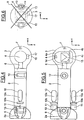
- the underwater vehicle comprises a front body 1 of generally cylindrical shape, and having a front end of generally hemispherical shape, a rear body 2, of generally cylindrical shape, and provided with a rear end 2a of truncated ogival shape a fairing 3 disposed between the front and rear bodies 2, in the general shape of a sphere truncated by two parallel planes equidistant from the center of said sphere and being connected to the front 1 and rear 2 bodies by generally toroidal shaped fillet-type connections, and a pivoting part 4 disposed in the fairing 3 about a longitudinal axis X of the underwater vehicle, lateral axis being noted Y and the axis of the depths or vertical axis being noted Z, according to the normal position of a machine in the water.
- the pivoting part 4 is supported by the front 1 and rear 2 bodies by means of trunnions, respectively 5 and 6.
- One of the two trunnions 5 or 6 is motorized, so that the rotation of the pivoting part 4 is controlled. .
- the pivoting part 4 can pivot more or less 180 ° around the X axis.
- the front body 1 comprises a camera 7 disposed at the hemispherical end made of transparent material to allow automatic guidance or remote control of the underwater vehicle.
- the front body 1 is also provided with a sonar 8 disposed on one side of the cylindrical portion of said front body 1.
- the rear body 2 is provided with a stabilizer 9 fixed at its truncated end ogival end 2a, cruciform and ensuring the stability of the displacement of the underwater vehicle in the water.
- the empennage 9 is fixed relative to the rear body 2.
- the longitudinal propulsion of the underwater vehicle is provided by two longitudinal thrusters 10 fixed on one side and the other of the rear body 2 in front of the empennage 9.
- the thrusters 10 are fixed relative to the rear body 2 and each comprise a cylindrical body 10a rounded at the ends provided with an electric motor and a faired propeller 10b driven by the electric motor of the body 10a and disposed between said body 10a and the empennage 9.
- the thrusters 10 provide the X-axis displacement and orientation of the underwater vehicle in a plane (X, Y), and are symmetrical with respect to a (X, Z) plane.
- the rear body 2 supports two tilting panels 11, arranged at a short distance behind the thrusters 10, to be located in the stream of water stirred by said thrusters 10.
- the tilting panels 11 are also symmetrical with respect to the plane ( X, Z) and allow orientation of the underwater vehicle towards the surface or on the contrary towards the seabed.
- the tilting panels 11 form elevators and pivot about an axis parallel to the Y axis, by means of actuators (not shown) arranged in the rear body 2.
- the vertical thrusters 12 and 13 allow the vehicle under -Marine to move along the Z axis, even in the absence of displacement along the X axis.
- the vertical thrusters 12 and 13 are well adapted to ensure the fine positioning of the submarine vehicle near an object in front of be identified and / or destroyed.
- the pivoting part 4, disposed in the fairing 3, has a shape of revolution with a substantially hemispherical head 4a, see figure 2 , a substantially cylindrical central portion 4b, and a flat rear portion 4c and connected to the central portion 4b by connecting fillet. Thanks to the journals 5 and 6, the pivoting part 4 can move in rotation about the axis X.
- a camera 14 is disposed in the front part 4a and an explosive charge 15, hollow charge type, is arranged in the central part. 4b and provided to deliver the energy of the explosion to the front portion 4a of the pivoting portion 4.
- the camera 14 and the explosive charge 15 are oriented substantially coaxially forward of the pivoting portion 4.
- the observation by the camera 14 and the destruction of a suspicious object can be performed in a plane transverse to the longitudinal axis X of the underwater vehicle.
- the orientation in a transverse plane of the pivoting part 4 makes it possible to tackle a suspicious object from above, by orienting the pivoting part 4 downwards, from below, by orienting the pivoting part 4 upwards as illustrated on FIG. figure 2 , which may be interesting in the caine mine orin, or by the side by orienting the pivoting part 4 on one side or the other of the underwater vehicle.
- all intermediate oblique orientations are possible.
- the fairing 3 is made of optically transparent material, so that the camera can observe an object which is in the vicinity of the underwater vehicle.
- the diameter of the fairing 3 may be greater than that of the rear body 2.
- the fairing 3 may be made of a transparent synthetic material, such as plexiglass, and is pierced with one or more holes 16 to allow its filling by the water when launching the submarine vehicle. It is thus possible to use a fairing 3 of small thickness which is not very resistant to the pressure exerted by the water and therefore of low mass, inexpensive and does not interfere with the optical observation or the effects of the explosion on the object. suspect.
- the underwater vehicle is also provided with an acoustic sensor 17, for example a sonar, supported by the central portion 4b of the pivoting part 4. It thus promotes the detection and location of the suspect object and the positioning end of the underwater vehicle with respect to the suspect object, especially in murky waters, for example loaded with sediments.
- the acoustic waves are transmitted by the water which is in the fairing 3, and by the fairing 3 made of acoustically transparent material.
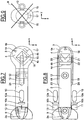
- the embodiment illustrated on the Figures 4 to 6 differs from the previous one in that the underwater vehicle is devoid of front body and associated sonar.
- the fairing 3 forms the front end of the underwater vehicle and is in the form of a truncated sphere on the rear side by a plane transverse to the longitudinal axis X and connecting to the rear body 2 by a connecting fillet of general toroidal shape.
- the pivoting part 4 is pivotally mounted on the single journal 6 secured to the rear body 2.
- the camera 14 and the acoustic sensor 17 allow the underwater vehicle to locate and recognize a suspicious object.
- the camera 7 is attached to the front of the fairing 3 and is oriented forward to provide vision in the direction of navigation.
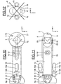
- the embodiment illustrated on the Figures 7 to 9 is closer to the previous by the presence of the fairing 3, forming the front end of the underwater vehicle.
- the underwater vehicle comprises two arms 18 and 19 parallel to the longitudinal axis X, fixed to the rear body 2 and extending partly along the rear body 2 and partly beyond said rear body 2 towards the rear body 2. before.
- the arms 18 and 19 are symmetrical about the plane (X, Z) and each support at their free end a pin 20, 21 on which is articulated the pivoting portion 4.
- the pins 20, 21 are aligned along an axis parallel to the transverse axis Y.
- An actuator 22 housed in the arm 19 makes it possible to control the pivoting position of the pivoting part 4. It can be provided that the part 4 pivots on an angle of at least plus or minus 90 °.
- the camera 14 can be used for viewing in the direction of navigation in the absence of a fixed camera.
- the fairing 3 has, seen from the front, a generally ellipsoidal shape having a height on the Z axis greater than its width on the Y axis and thus allowing the pivoting part 4 to have sufficient space inside. of said fairing 3.
- the portion of the arms 18 and 19 attached to the rear body 2 may also be covered by a fairing portion 23, 24, of profiled shape, providing a lower resistance to advance in the water.
- the portion of the arms 18 and 19 projecting from the rear body 2 is disposed in the fairing 3.
- the pivoting portion 4 can be directed towards the front of the vehicle, so as to detect any obstacles.
- the pivoting part 4 can scan the possible pivot range to increase the probability of detection of a suspicious object.
- the pivoting portion 4 is then inclined to the desired angle ensuring the best probability of destruction according to the shape and characteristics of the suspect object.
- the illustrated embodiment Figures 10 to 12 differs from the previous in that the fairing 3 is fixed integrally to the pivoting part 4 and the fixed part 2 has a connection with the fairing 3 by means of the arms 18 and 19 arranged laterally on either side of the fairing 3
- the shroud 3 has a circular section in section along a plane parallel to the plane (X, Z) and pivots about the Y axis. The hydrodynamics is preserved during rotation. In section along a plane passing through the pivot axis, the fairing 3 is of substantially ellipsoidal shape. The fairing 3 is resistant to pressure and therefore devoid of hole.
- the pivoting portion provided with at least one sensor is disposed inside a fairing so that the pivoting of said pivoting part does not modify the flow. water along its outer walls.
- the hydrodynamics of the underwater vehicle is independent of the orientation of the pivoting part 4. This ensures a precise positioning and easier, avoiding the change of inclination of a projecting member , for example the acoustic sensor 17, does not come to modify the flow of water along the underwater vehicle and obliges to restore the position of the underwater vehicle by an action on the vertical thrusters 12 and 13, on the thrusters longitudinal 10 on the tilting panels 11, or on the pivoting portion 4 itself.
- This advantage is even more important in the case of strong marine currents, which result in a high relative speed of the underwater vehicle with respect to water and a zero or near zero relative speed of the underwater vehicle compared to the sea. suspicious object.
- a modification of the hydrodynamics may cause either an inadvertent removal of the underwater vehicle from the suspect object or a direct impact, which may damage the underwater vehicle without putting the explosive charge under ideal operating conditions, a hollow charge that may require some distance from the target and suspect to destroy to achieve maximum destruction effect.
- the piloting of the underwater vehicle is thus made simpler and the destruction of the suspect object can be conducted more quickly, which results in a significant savings in operating cost, insofar as the ship or the aircraft having dropped the underwater vehicle for the purpose of destroying the suspect object, it generally remains near the area where the suspect object is located until it is destroyed.
Description
- La présente invention concerne le domaine des dispositifs de la destruction d'objets sous-marins ou flottants susceptibles de présenter un danger pour la navigation, par exemple les mines.
- On connaît deux types principaux de mines: les mines de fond qui reposent au fond de l'eau, et les mines à orin qui sont retenues par un câble appelé "orin" à une gueuse. La destruction des mines de fond s'effectue par dépose d'une charge d'explosif appelée "charge militaire" à proximité immédiate de l'objet sous-marin et explosion. Cette façon d'opérer nécessite de repérer la mine puis d'amener la charge militaire à proximité et enfin de provoquer l'explosion, par opposition au dragage de mines qui met généralement en oeuvre des moyens magnéto-acoustiques et/ou mécaniques pour déclencher les mines ou couper leur orin.
- Les procédés connus de destruction d'une mine sous-marine de fond comportent une étape de détection et/ou d'identification de la mine et une étape de destruction de la mine au moyen d'une charge explosive importante, par exemple de l'ordre de 50 à 100 kgs, déposée à une distance de quelques mètres de la mine à détruire, au moyen d'un véhicule sous-marin, généralement télécommandé. Après avoir procédé à la récupération du véhicule sous-marin à bord d'un vaisseau de surface chasseur de mines, on procède à la destruction de la mine en provoquant l'explosion de la charge dont l'onde de choc provoque l'explosion de la mine par influence. Les mines à orin sont détruites selon un procédé similaire de détection et/ou d'identification qui est suivi d'une étape consistant à accrocher sur l'orin une cisaille pyrotechnique qui est mise en place au moyen d'un véhicule sous-marin télécommandé ou filoguidé. Ici encore, après avoir récupéré le véhicule sous-marin, on provoque l'actionnement pyrotechnique de la cisaille par commande à distance depuis le vaisseau de surface. La mine remonte à la surface et est détruite par un moyen annexe tel qu'un canon. Or, les mines de fond modernes peuvent ne plus exploser par influence et la destruction au canon des flotteurs des mines à orin cisaillés ou des mines dérivant en surface est difficile par mer agitée et/ou mauvaise visibilité. Il est donc nécessaire de positionner de façon très précise la charge militaire par rapport à la mine pour garantir sa destruction. Ceci est également vrai pour les mines à orin que l'on souhaite détruire directement, ce qui s'avère relativement difficile, notamment en cas de présence de courant sous-marin. De plus, la récupération du véhicule sous-marin prend du temps.
- Différents types de véhicules sous-marins télécommandés ou filoguidés sont connus notamment par les brevets de la Société ECA, notamment
FR-2 684 951 EP-0 612 656 . - Parmi ces véhicules, on trouve également les véhicules consommables.
- Les engins conventionnels monocorps ne permettent pas d'observer puis d'attaquer des objets par le dessus, le dessous, ou le côté, sauf à disposer d'une architecture de propulseur permettant d'orienter l'engin. Ceci conduit à la présence d'un grand nombre de propulseurs, ce qui augmente de façon significative le coût de l'engin. Même pourvu de nombreux propulseurs, l'engin ne parvient pas à travailler à de grands angles d'inclinaison, de l'ordre de 50 à 60°, ou plus. Ceci est d'autant plus vrai en présence de courants marins, où un tel engin aura beaucoup de difficulté à conserver sa stabilité et à assurer son maintien en position.
- Le document
WO 01/38169 - Toutefois, la demanderesse s'est aperçue que le pivotement de la deuxième partie risquait de modifier les caractéristiques hydrodynamiques du véhicule, et par voie de conséquence, de provoquer un déplacement non souhaité du véhicule submersible par rapport à l'objet sous-marin.
- L'invention vise à remédier à ces inconvénients.
- L'invention propose un véhicule de destruction d'objets sous-marins peu sensible au pivotement de la deuxième partie.
- L'invention propose un véhicule consommable de destruction d'objets sous-marins, apte à une destruction plus sûre et plus fiable.
- Le dispositif, selon un aspect de l'invention, est destiné à la destruction d'objets sous-marins flottants. Le dispositif comprend une première partie pourvue de moyens de propulsion et une deuxième partie étant apte à pivoter par rapport à la première partie suivant au moins un axe, de façon que le dispositif puisse approcher un objet sous-marin selon différentes orientations. Le dispositif comprend au moins un carénage de protection de la deuxième partie de manière que les caractéristiques hydrodynamiques du dispositif soient indépendantes de l'orientation de la deuxième partie relativement à la première partie. Le carénage est perméable à l'eau.
- Selon un autre mode de réalisation, le carénage peut être une coque résistante à la pression hydrostatique, solidaire de la première partie ou de la deuxième partie.
- Ainsi, la deuxième partie entourée par le carénage peut pivoter, l'hydrodynamique du dispositif étant conservée. Les caractéristiques de mobilité de l'engin sont conservées, d'où un pilotage plus facile, une amenée en position de tir plus rapide, un fonctionnement plus fiable, et un taux de réussite de la destruction plus élevé. D'éventuels capteurs en saillie sur la deuxième partie disposés à l'intérieur du carénage, peuvent pivoter en ne provoquant qu'une modification marginale voire nulle de la résistance à l'eau.
- Avantageusement, le dispositif comprend des moyens de pivotement de la deuxième partie par rapport à la première partie, les moyens de pivotement étant pourvus d'au moins un moteur.
- Dans un mode de réalisation de l'invention, l'axe de pivotement est transversal.
- Dans un mode de réalisation de l'invention, l'axe de pivotement est longitudinal.
- Dans un mode de réalisation de l'invention, l'axe de pivotement est vertical.
- Une combinaison de deux axes de pivotement est possible.
- Avantageusement, le carénage est sensiblement transparent acoustiquement.
- Avantageusement, le carénage est sensiblement transparent optiquement. Le carénage peut être réalisé en plexiglas® par exemple.
- Dans un mode de réalisation de l'invention, le carénage est fixé sur la première partie pour améliorer l'hydrodynamique dans toutes les phases de navigation et protéger la deuxième partie contre des débris susceptibles d'être rencontrés. Le carénage peut être fixé à l'avant de la première partie. Le carénage peut être fixé à sensiblement au centre de la première partie. Le carénage peut se présenter sous la forme d'une portion de sphère ou de cylindre ou d'une combinaison des deux se raccordant à un corps cylindrique de la première partie.
- Dans un autre mode de réalisation de l'invention, le carénage est fixé sur la deuxième partie.
- Dans un mode de réalisation de l'invention, le carénage présente une forme hydrodynamiquement isotrope.
- Dans un mode de réalisation de l'invention, le carénage présente une symétrie de révolution par rapport à l'axe de pivotement.
- Dans un mode de réalisation de l'invention, la deuxième partie comprend au moins un moyen d'observation d'objets sous-marins, par exemple une caméra.
- Dans un mode de réalisation de l'invention, la deuxième partie comprend au moins un moyen d'identification d'objets sous-marins.
- Dans un mode de réalisation de l'invention, la deuxième partie comprend au moins un moyen de localisation d'un objet sous-marin, par exemple un son ar.
- Dans un mode de réalisation de l'invention, la deuxième partie comprend au moins un moyen d'estimation de la distance par rapport audit objet sous-marin.
- Dans un mode de réalisation de l'invention, la deuxième partie comprend au moins un moyen de classification d'objets sous-marins.
- Dans un mode de réalisation de l'invention, la deuxième partie comprend au moins un moyen d'attaque.
- Le véhicule peut être déployé depuis un vaisseau de surface, mais également depuis un aéronef. Dans ce dernier cas, un relais à la surface de l'eau permet de transformer les signaux acoustiques émis par le véhicule sou s-marin en signaux radio ou optiques ou électriques, pour leur envoi vers l'aéronef. La charge militaire sera généralement une charge creuse dont l'explosion produit un effet principal selon un axe, d'où l'importance du positionnement par rapport à l'objet sous-marin à détruire, et ce d'autant plus que chaque type de mine possède des zones plus sensibles ou fragiles que d'autres à une explosion externe.
- Le pivotement de la partie basculante avec une charge de destruction et au moins un capteur ne modifie pas sensiblement les caractéristiques hydrodynamiques du véhicule dont le pilotage, manuel télécommandé ou automatique, s'en trouve facilité.
- La présente invention sera mieux comprise à l'étude de la description détaillée d'un mode de réalisation particulier pris à titre d'exemple nullement limitatif et illustré par les dessins annexés, sur lesquels:
- la
figure 1 est une vue de côté en élévation d'un véhicule sous-marin selon un mode de réalisation de l'invention; - la
figure 2 est une vue de dessus en élévation du véhicule sous-marin de lafigure 1 ; - la
figure 3 est une vue de face schématique du véhicule sous-marin de lafigure 1 ; - la
figure 4 est une vue de côté en élévation d'un véhicule sous-marin selon un autre mode de réalisation de l'invention; - la
figure 5 est une vue de dessus en élévation du véhicule sous-marin de lafigure 4 ; - la
figure 6 est une vue schématique de face du véhicule sous-marin de lafigure 4 ; - la
figure 7 est une vue de côté en élévation d'un véhicule sous-marin selon un autre mode de réalisation de l'invention; - la
figure 8 est une vue de dessus en élévation du véhicule sous-marin de lafigure 7 ; - la
figure 9 est une vue schématique de face du véhicule sous-marin de lafigure 7 ; - la
figure 10 est une vue de côté en élévation d'un véhicule sous-marin selon un autre mode de réalisation de l'invention; - la
figure 11 est une vue de dessus en élévation du véhicule sous-marin de lafigure 7 ; et - la
figure 12 est une vue schématique de face du véhicule sous-marin de lafigure 7 . - Comme on peut le voir sur les
figures 1 à 3 , le véhicule sous-marin comprend un corps avant 1, de forme générale cylindrique, et présentant une extrémité avant la de forme générale hémisphérique, un corps arrière 2, de forme générale cylindrique, et pourvu d'une extrémité arrière 2a de forme ogivale tronquée, un carénage 3 disposé entre les corps avant 1 et arrière 2, en forme générale de sphère tronquée par deux plans parallèles équidistants du centre de ladite sphère et se raccordant aux corps avant 1 et arrière 2 par des congés de raccordement de forme générale toroïdale, et une partie pivotante 4 disposée dans le carénage 3 autour d'un axe longitudinal X du véhicule sous-marin, l'axe latéral étant noté Y et l'axe des profondeurs ou axe vertical étant noté Z, selon la position normale d'un engin dans l'eau. - La partie pivotante 4 est supportée par les corps avant 1 et arrière 2 par l'intermédiaire de tourillons, respectivement 5 et 6. L'un des deux tourillons 5 ou 6 est motorisé, de façon que la rotation de la partie pivotante 4 soit commandée. La partie pivotante 4 peut effectuer un pivotement de plus ou moins 180° autour de l'axe X.
- Le corps avant 1 comprend une caméra 7 disposée à l'extrémité hémisphérique la réalisée en matériau transparent pour permettre un guidage automatique ou télécommandé du véhicule sous-marin. Le corps avant 1 est également pourvu d'un sonar 8 disposé sur un côté de la portion cylindrique dudit corps pavant 1.
- Le corps arrière 2 est pourvu d'un empennage 9 fixé à son extrémité ogivale tronquée 2a, cruciforme et assurant la stabilité du déplacement du véhicule sous-marin dans l'eau. L'empennage 9 est fixe par rapport au corps arrière 2. La propulsion longitudinale du véhicule sous-marin est assurée par deux propulseurs longitudinaux 10 fixés sur un côté et l'autre du corps arrière 2 en avant de l'empennage 9. Les propulseurs 10 sont fixes par rapport au corps arrière 2 et comprennent chacun un corps 10a de forme cylindrique arrondie aux extrémités pourvu d'un moteur électrique et une hélice carénée 10b entraînée par le moteur électrique du corps 10a et disposée entre ledit corps 10a et l'empennage 9. Les propulseurs 10 assurent le déplacement suivant l'axe X et l'orientation du véhicule sous-marin dans un plan (X, Y), et sont symétriques par rapport à un plan (X, Z).
- Le corps arrière 2 supporte deux panneaux inclinables 11, disposés à une faible distance à l'arrière des propulseurs 10, pour se situer dans le flux d'eau brassé par lesdits propulseurs 10. Les panneaux inclinables 11 sont également symétriques par rapport au plan (X, Z) et permettent une orientation du véhicule sous-marin vers la surface ou au contraire vers le fond marin. Les panneaux inclinables 11 forment des gouvernes de profondeur et pivotent autour d'un axe parallèle à l'axe Y, au moyen d'actionneurs non représentés disposés dans le corps arrière 2.
- Il est encore prévu deux propulseurs verticaux 12 et 13, disposés dans le corps arrière 2, l'un à proximité du carénage 3, l'autre sensiblement au niveau de l'empennage arrière 9. Les propulseurs verticaux 12 et 13 permettent au véhicule sous-marin de se déplacer selon l'axe Z, même en l'absence de déplacement selon l'axe X. Les propulseurs verticaux 12 et 13 sont bien adaptés pour assurer le positionnement fin du véhicule sous-marin à proximité d'un objet devant être identifié et/ou détruit.
- La partie pivotante 4, disposée dans le carénage 3, présente une forme de révolution avec une tête sensiblement hémisphérique 4a, voir
figure 2 , une partie centrale 4b sensiblement cylindrique, et une partie arrière 4c plate et reliée à la partie centrale 4b par des congés de raccordement. Grâce aux tourillons 5 et 6, la partie pivotante 4 peut se déplacer en rotation autour de l'axe X. Une caméra 14 est disposée dans la partie avant 4a et une charge explosive 15, de type charge creuse, est disposée dans la partie centrale 4b et prévue pour délivrer l'énerg ie de l'explosion vers la partie avant 4a de la partie pivotante 4. La camé ra 14 et la charge explosive 15 sont orientées sensiblement coaxialement vers l'avant de la partie pivotante 4. - En d'autres termes, l'observation par la caméra 14 et la destruction d'un objet suspect peuvent être effectuées dans un plan transversal à l'axe longitudinal X du véhicule sous-marin. L'orientation dans un plan transversal de la partie pivotante 4 permet d'aborder un objet suspect par le dessus, en orientant la partie pivotante 4 vers le bas, par en dessous, en orientant la partie pivotante 4 vers le haut comme illustré sur la
figure 2 , ce qui peut s'avérer intéressant dans le c as de mines à orin, ou encore par le côté en orientant la partie pivotante 4 d'un côté ou de l'autre du véhicule sous-marin. Bien entendu, toutes les orientations obliques intermédiaires sont possibles. - Le carénage 3 est réalisé en matériau transparent optiquement, de façon que la caméra puisse observer un objet qui se trouve au vois inage du véhicule sous-marin. Le diamètre du carénage 3 peut être supérieur à celui du corps arrière 2. Le carénage 3 peut être réalisé en un matériau synthétique transparent, tel que du plexiglas, et est percé d'un ou plusieurs trous 16 pour permettre son remplissage par de l'eau lors de la mise à l'eau du véhicule sous-marin. On peut ainsi utiliser un carénage 3 de faible épaisseur, peu résistant à la pression exercée par l'eau et par conséquent de faible masse, peu coûteux et ne gênant ni l'observation optique, ni les effets de l'explosion sur l'objet suspect.
- De façon optionnelle et tel que représenté sur la
figure 1 , le véhicule sous-marin est également pourvu d'un capteur acoustique 17, par exemple un sonar, supporté par la portion centrale 4b de la partie pivotante 4. On favorise ainsi la détection et la localisation de l'objet suspect ainsi que le positionnement fin du véhicule sous-marin par rapport à l'objet suspect, en particulier dans des eaux troubles, par exemple chargées de sédiments. Les ondes acoustiques sont transmises par l'eau qui se trouve dans le carénage 3, et par le carénage 3 réalisé en matériau acoustiquement transparent. - Le mode de réalisation illustré sur les
figures 4 à 6 se distingue du précédent en ce que le véhicule sous-marin est dépourvu de corps avant et du sonar associé. Le carénage 3 forme l'extrémité avant du véhicule sous-marin et se présente sous la forme d'une sphère tronquée du côté arrière par un plan transversal à l'axe longitudinal X et se raccordant au corps arrière 2 par un congé de raccordement de forme générale toroïdale. La partie pivotante 4 est montée à pivotement sur le seul tourillon 6 solidaire du corps arrière 2. La caméra 14 et le capteur acoustique 17 permettent au véhicule sous-marin de localiser et de reconnaître un objet suspect. La caméra 7 est fixée à l'avant du carénage 3 et est orientée vers l'avant pour assurer la vision dans le sens de la navigation. - Le mode de réalisation illustré sur les
figures 7 à 9 se rapproche du précédent par la présence du carénage 3, formant l'extrémité avant du véhicule sous-marin. Le véhicule sous-marin comprend deux bras 1 8 et 19 parallèles à l'axe longitudinal X, fixés au corps arrière 2 et s'étendant en partie le long du corps arrière 2 et en partie au-delà dudit corps arrière 2 vers l'avant. Les bras 18 et 19 sont symétriques par rapport au plan (X, Z) et supportent chacun à leur extrémité libre un tourillon 20, 21 sur lequel est articulée la partie pivotante 4. Les tourillons 20, 21 sont alignés selon un axe parallèle à l'axe transversal Y. Un actionneur 22 logé dans le bras 19 permet de commander la position de pivotement de la partie pivotante 4. On peut prévoir que la partie 4 pivote sur un angle d'au moins plus ou moins 90°. La caméra 14 peut servir à la vision dans le sens de la navigation en l'absence de caméra fixe. - Comme on le voit plus particulièrement sur la
figure 9 , le carénage 3 présente, vue de face, une forme généralement ellipsoïdale présentant une hauteur sur l'axe Z supérieure à sa largeur sur l'axe Y et permettant ainsi à la partie pivotante 4 de disposer de l'espace suffisant à l'intérieur dudit carénage 3. La partie des bras 18 et 19 fixée au corps arrière 2 peut également être recouverte par une portion de carénage 23, 24, de forme profilée, assurant une moindre résistance à l'avancement dans l'eau. La partie des bras 18 et 19 en saillie par rapport au corps arrière 2 est disposée dans le carénage 3. - Lors d'une phase d'approche, la partie pivotante 4 peut être dirigée vers l'avant du véhicule, de façon à pouvoir détecter d'éventuels obstacles. Lors d'une phase de recherche d'un objet suspect, la partie pivotante 4 peut balayer la plage de pivotement possible pour augmenter la probabilité de détection d'un objet suspect. Lors d'une phase de destruction, la partie pivotante 4 est alors inclinée jusqu'à l'angle voulu assurant la meilleure probabilité de destruction en fonction de la forme et des caractéristiques de l'objet suspect.
- Le mode de réalisation illustré
figures 10 à 12 se distingue du précédent par le fait que le carénage 3 est fixé solidairement à la partie pivotante 4 et que la partie fixe 2 présente un raccordement avec le carénage 3 au moyen des bras 18 et 19 disposés latéralement de part et d'autre du carénage 3. Le carénage 3 présente une section circulaire en coupe selon un plan parallèle au plan (X, Z) et pivote autour de l'axe Y. L'hydrodynamique est conservée lors de la rotation. En coupe selon un plan passant par l'axe de pivotement, le carénage 3 est de forme sensiblement ellipsoïdale. Le carénage 3 est résistant à la pression et donc dépourvu de trou. - Dans les trois modes de réalisation précités , la partie pivotante pourvue d'au moins un capteur, par exemple optique ou acoustique, est disposée à l'intérieur d'un carénage de façon que le pivotement de ladite partie pivotante ne modifie pas l'écoulement de l'eau le long de ses parois extérieures. En d'autres termes, l'hydrodynamique du véhicule sous-marin est indépendant de l'orientation de la partie pivotante 4. On assure ainsi un positionnement précis et plus facile, en évitant que la modification d'inclinaison d'un organe en saillie, par exemple le capteur acoustique 17, ne vienne modifier l'écoulement de l'eau le long du véhicule sous-marin et oblige à rétablir la position du véhicule sous-marin par une action sur les propulseurs verticaux 12 et 13, sur les propulseurs longitudinaux 10, sur les panneaux inclinables 11, ou encore sur la partie pivotante 4 elle-même. Cet avantage est encore plus important dans le cas de courants marins forts, qui se traduisent par une vitesse relative élevée du véhicule sous-marin par rapport à l'eau et une vitesse relative nulle ou quasi nulle du véhicule sous-marin par rapport à l'objet suspect. Une modification de l'hydrodynamique risque, dans un tel cas, de provoquer, soit un éloignement intempes tif du véhicule sous-marin par rapport à l'objet suspect, soit un choc direct, risquant de détériorer le véhicule sous-marin sans mettre la charge explosive dans des conditions idéales de fonctionnement, une charge creuse pouvant nécessiter une certaine distance par rapport à l'obj et suspect à détruire pour obtenir un effet de destruction maximal.
- Le pilotage du véhicule sous-marin est ainsi rendu plus simple et la destruction de l'objet suspect peut être menée plus rapidement, ce qui se traduit par une économie non négligeable de coût de fonctionnement, dans la mesure où le navire ou l'aéronef ayant largué le véhicule sous-marin en vue de la destruction de l'objet suspect, reste en général à proximité de la zone où se trouve l'objet suspect jusqu'à sa destruction.
Claims (16)
- Dispositif consommable sous-marin de destruction de mines de fond ou de mines à orin comprenant une première partie (2) pourvue de moyens de propulsion et une deuxième partie (4) apte à pivoter par rapport à la première partie suivant au moins un axe, de façon que le dispositif puisse approcher un objet sous-marin selon différentes orientations, caractérisé par le fait qu'il comprend un carénage (3) de protection de la deuxième partie (4) de manière que les caractéristiques hydrodynamiques du dispositif soient indépendantes de l'orientation de la deuxième partie (4) relativement à la première partie (2) et qu'il comprend deux propulseurs longitudinaux fixés d'un côté et de l'autre de la première partie (2) en avant d'un empennage fixe et deux propulseurs verticaux disposés dans la première partie, l'un à proximité du carénage (3) et l'autre au niveau de l'empennage fixe.
- Dispositif selon la revendication 1, dans lequel le carénage est perméable à l'eau.
- Dispositif selon la revendication 1, dans lequel le carénage forme une coque résistant à la pression hydrostatique.
- Dispositif selon l'une quelconque des revendications précédentes, comprenant des moyens de pivotement de la deuxième partie par rapport à la première partie, les moyens de pivotement étant pourvus d'au moins un moteur.
- Dispositif selon l'une quelconque des revendications 1 à 4, dans lequel l'axe de pivotement est transversal.
- Dispositif selon l'une quelconque des revendications 1 à 4, dans lequel l'axe de pivotement est longitudinal.
- Dispositif selon l'une quelconque des revendications 1 à 4, dans lequel l'axe de pivotement est vertical.
- Dispositif selon l'une quelconque des revendications 1 à 4, dans lequel le pivotement se fait autour de deux axes.
- Dispositif selon l'une quelconque des revendications précédentes, dans lequel le carénage (3) est sensiblement transparent acoustiquement.
- Dispositif selon l'une quelconque des revendications précédentes, dans lequel le carénage (3) est sensiblement transparent optiquement.
- Dispositif selon l'une quelconque des revendications précédentes, dans lequel le carénage (3) est fixé sur la première partie (2).
- Dispositif selon la revendication 11, dans lequel le carénage (3) est fixé à l'avant de la première partie (2).
- Dispositif selon la revendication 11, dans lequel le carénage est fixé sensiblement au centre de la première partie.
- Dispositif selon l'une quelconque des revendications 1 à 10, dans lequel le carénage est fixé sur la deuxième partie.
- Dispositif selon l'une quelconque des revendications précédentes, dans lequel le carénage présente une symétrie de révolution par rapport à l'axe de pivotement.
- Dispositif selon l'une quelconque des revendications précédentes, dans lequel la deuxième partie comprend au moins un moyen d'observation d'objets sous-marins, et/ou au moins un moyen d'identification d'objets sous-marins, et/ou au moins un moyen de localisation d'un objet sous-marin, et/ou au moins un moyen d'estimation de la distance par rapport audit objet sous-marin, et/ou au moins un moyen de classification d'objets sous-marins et/ou au moins un moyen d'attaque.
Priority Applications (1)
| Application Number | Priority Date | Filing Date | Title |
|---|---|---|---|
| PL04805232T PL1794049T5 (pl) | 2004-09-29 | 2004-09-29 | Urządzenie do niszczenia obiektów podwodnych lub pływających |
Applications Claiming Priority (1)
| Application Number | Priority Date | Filing Date | Title |
|---|---|---|---|
| PCT/FR2004/002466 WO2006035121A1 (fr) | 2004-09-29 | 2004-09-29 | Dispositif de destruction d'objets sous-marins ou flottants |
Publications (3)
| Publication Number | Publication Date |
|---|---|
| EP1794049A1 EP1794049A1 (fr) | 2007-06-13 |
| EP1794049B1 EP1794049B1 (fr) | 2010-06-16 |
| EP1794049B2 true EP1794049B2 (fr) | 2017-06-07 |
Family
ID=34960236
Family Applications (1)
| Application Number | Title | Priority Date | Filing Date |
|---|---|---|---|
| EP04805232.8A Active EP1794049B2 (fr) | 2004-09-29 | 2004-09-29 | Dispositif de destruction d'objets sous-marins ou flottants |
Country Status (6)
| Country | Link |
|---|---|
| US (1) | US7752990B2 (fr) |
| EP (1) | EP1794049B2 (fr) |
| DE (1) | DE602004027765D1 (fr) |
| NO (1) | NO339860B1 (fr) |
| PL (1) | PL1794049T5 (fr) |
| WO (1) | WO2006035121A1 (fr) |
Families Citing this family (6)
| Publication number | Priority date | Publication date | Assignee | Title |
|---|---|---|---|---|
| DE102010033638A1 (de) * | 2010-08-06 | 2012-02-09 | Atlas Elektronik Gmbh | Kampfmittelräumgerät zum Räumen von Kampfmitteln, wie Seeminen, unter Wasser, unbemanntes Unterwasserfahrzeug mit derartigem Kampfmittelräumgerät sowie Verfahren hierzu |
| FR2969573B1 (fr) | 2010-12-23 | 2013-02-08 | Eca | Dispositif de mise a l'eau et de recuperation d'un engin submersible ou de surface. |
| DE102011018304A1 (de) * | 2011-02-15 | 2012-08-16 | Atlas Elektronik Gmbh | Unbemanntes Unterwasserfahrzeug, daran fixierbarer Austauschkörper, System mit dem unbemannten Unterwasserfahrzeug und dem Austauschkörper sowie Verfahren zum Betreiben eines unbemannten Unterwasserfahrzeugs |
| DE102011121856A1 (de) * | 2011-12-21 | 2013-06-27 | Atlas Elektronik Gmbh | Kampfmittelräumgerät zum Räumen von Kampfmitteln, wie Seeminen, unter Wasser, Kampfmittelräumkombination mit unbemanntem Unterwasserfahrzeug und derartigem Kampfmittelräumgerät sowie Verfahren hierzu. |
| DE102012006566A1 (de) * | 2012-03-30 | 2013-10-02 | Atlas Elektronik Gmbh | Verfahren zur Detektion von Seeminen und Seeminendetektionssystem |
| CN110217362B (zh) * | 2019-05-08 | 2020-05-29 | 上海海事大学 | 一种子母式逃逸型载人潜水器 |
Citations (9)
| Publication number | Priority date | Publication date | Assignee | Title |
|---|---|---|---|---|
| US3448710A (en) † | 1967-05-04 | 1969-06-10 | Thomas Gaskins | Propelling and steering device |
| US3604661A (en) † | 1969-09-25 | 1971-09-14 | Robert Alfred Mayer Jr | Boundary layer control means |
| DE3605579C1 (en) † | 1986-02-21 | 1987-05-07 | Messerschmitt Boelkow Blohm | Missile for attacking targets underneath the flight path (trajectory) of the missile |
| US4992999A (en) † | 1966-07-28 | 1991-02-12 | The United States Of America As Represented By The Secretary Of The Navy | Submarine drone for carrying a barrel stave-type transducer array |
| DE3927724A1 (de) † | 1989-08-23 | 1993-02-25 | Nord Systemtechnik | Unterwasserfahrzeug |
| DE19516341A1 (de) † | 1995-05-04 | 1996-11-07 | Rheinmetall Ind Ag | Flugkörper mit einem schwenkbaren Gefechtskopf |
| DE19813376A1 (de) † | 1998-03-26 | 1999-09-30 | Diehl Stiftung & Co | Gefechtskopf für Flugkörper |
| US20020162515A1 (en) † | 2000-09-06 | 2002-11-07 | Secil Boyd | Support platform and structure for fish farming ("artificial island reef platform") |
| US6606960B1 (en) † | 2001-02-15 | 2003-08-19 | The United States Of America As Represented By The Secretary Of The Navy | SCUBA diver fairing |
Family Cites Families (4)
| Publication number | Priority date | Publication date | Assignee | Title |
|---|---|---|---|---|
| FR2684951A1 (fr) * | 1991-12-17 | 1993-06-18 | Eca | Procede de destruction d'un objet sous-marin, et notamment d'une mine immergee. |
| FR2701918B1 (fr) * | 1993-02-23 | 1995-04-28 | Eca | Procédé perfectionné de destruction d'un objet sous-marin, et notamment d'une mine immergée. |
| GB2305399B (en) * | 1995-09-21 | 1999-05-19 | Marconi Gec Ltd | A submersible mine neutralisation vehicle |
| FR2801274B1 (fr) * | 1999-11-24 | 2001-12-28 | Eca | Dispositif de destruction d'objets sous-marins |
-
2004
- 2004-09-29 EP EP04805232.8A patent/EP1794049B2/fr active Active
- 2004-09-29 WO PCT/FR2004/002466 patent/WO2006035121A1/fr active Application Filing
- 2004-09-29 PL PL04805232T patent/PL1794049T5/pl unknown
- 2004-09-29 US US11/664,310 patent/US7752990B2/en active Active
- 2004-09-29 DE DE200460027765 patent/DE602004027765D1/de active Active
-
2007
- 2007-04-26 NO NO20072156A patent/NO339860B1/no unknown
Patent Citations (9)
| Publication number | Priority date | Publication date | Assignee | Title |
|---|---|---|---|---|
| US4992999A (en) † | 1966-07-28 | 1991-02-12 | The United States Of America As Represented By The Secretary Of The Navy | Submarine drone for carrying a barrel stave-type transducer array |
| US3448710A (en) † | 1967-05-04 | 1969-06-10 | Thomas Gaskins | Propelling and steering device |
| US3604661A (en) † | 1969-09-25 | 1971-09-14 | Robert Alfred Mayer Jr | Boundary layer control means |
| DE3605579C1 (en) † | 1986-02-21 | 1987-05-07 | Messerschmitt Boelkow Blohm | Missile for attacking targets underneath the flight path (trajectory) of the missile |
| DE3927724A1 (de) † | 1989-08-23 | 1993-02-25 | Nord Systemtechnik | Unterwasserfahrzeug |
| DE19516341A1 (de) † | 1995-05-04 | 1996-11-07 | Rheinmetall Ind Ag | Flugkörper mit einem schwenkbaren Gefechtskopf |
| DE19813376A1 (de) † | 1998-03-26 | 1999-09-30 | Diehl Stiftung & Co | Gefechtskopf für Flugkörper |
| US20020162515A1 (en) † | 2000-09-06 | 2002-11-07 | Secil Boyd | Support platform and structure for fish farming ("artificial island reef platform") |
| US6606960B1 (en) † | 2001-02-15 | 2003-08-19 | The United States Of America As Represented By The Secretary Of The Navy | SCUBA diver fairing |
Also Published As
| Publication number | Publication date |
|---|---|
| US7752990B2 (en) | 2010-07-13 |
| PL1794049T5 (pl) | 2018-05-30 |
| DE602004027765D1 (de) | 2010-07-29 |
| NO339860B1 (no) | 2017-02-06 |
| EP1794049B1 (fr) | 2010-06-16 |
| PL1794049T3 (pl) | 2010-10-29 |
| WO2006035121A1 (fr) | 2006-04-06 |
| EP1794049A1 (fr) | 2007-06-13 |
| US20080127876A1 (en) | 2008-06-05 |
| NO20072156L (no) | 2007-06-27 |
Similar Documents
| Publication | Publication Date | Title |
|---|---|---|
| EP0787095B1 (fr) | Procede et systeme de destruction d'objets sous-marins, notamment de mines sous-marines | |
| EP2551185B1 (fr) | Engin marin ou sous-marin et procédé d'arrimage associé | |
| CA2997512C (fr) | Agencement de corps de remorquage pour un dispositif remorquable dans un systeme sonar | |
| EP1794049B2 (fr) | Dispositif de destruction d'objets sous-marins ou flottants | |
| US6095078A (en) | Submarine propulsion control system | |
| EP3906188B1 (fr) | Dispositif d'accueil pour un vehicule sous-marin | |
| EP0547937B1 (fr) | nrocédé de destruction d'un objet sous-marin, et notamment d'une mine immergée | |
| EP1147045B1 (fr) | Dispositif de destruction d'objets sous-marins | |
| FR2679023A1 (fr) | Procede et dispositif pour combattre un objectif immerge. | |
| US6058847A (en) | Submersible mine neutralisation vehicle | |
| WO2023275476A1 (fr) | Dispositif de mise à la verticale pour véhicule sous-marin | |
| EP1582455B1 (fr) | Dispositif d'observation d'objets sous-marins | |
| EP0347288B1 (fr) | Véhicule sous-marin autopropulsé pour la détection d'objets immergés | |
| WO2010119195A1 (fr) | Périscope flottant notamment pour un engin sous-marin | |
| EP0847361B1 (fr) | Systeme de propulsion sous-marin | |
| EP0467765B1 (fr) | Procédé et système de mesure à la traîne dans l'eau, sous hélicoptère | |
| EP3999801B1 (fr) | Détecteur de lancement d'un projectile, projectile et ensemble de lancement associés | |
| EP2322420B1 (fr) | Véhicule naval de surface à bras instrumenté pivotant. | |
| WO2019120928A1 (fr) | Vehicule apte a etre immerge comprenant un mat | |
| FR2668446A1 (fr) | Perfectionnements apportes aux engins sous-marins filo-guides. | |
| WO2023175264A1 (fr) | Véhicule tracté sous-marin et système de récupération d'un tel véhicule sous-marin | |
| EP0289692A1 (fr) | Dispositif de dragage |
Legal Events
| Date | Code | Title | Description |
|---|---|---|---|
| PUAI | Public reference made under article 153(3) epc to a published international application that has entered the european phase |
Free format text: ORIGINAL CODE: 0009012 |
|
| 17P | Request for examination filed |
Effective date: 20070312 |
|
| AK | Designated contracting states |
Kind code of ref document: A1 Designated state(s): DE FR GB IT PL |
|
| DAX | Request for extension of the european patent (deleted) | ||
| RBV | Designated contracting states (corrected) |
Designated state(s): DE FR GB IT PL |
|
| 17Q | First examination report despatched |
Effective date: 20090505 |
|
| GRAP | Despatch of communication of intention to grant a patent |
Free format text: ORIGINAL CODE: EPIDOSNIGR1 |
|
| GRAS | Grant fee paid |
Free format text: ORIGINAL CODE: EPIDOSNIGR3 |
|
| GRAA | (expected) grant |
Free format text: ORIGINAL CODE: 0009210 |
|
| AK | Designated contracting states |
Kind code of ref document: B1 Designated state(s): DE FR GB IT PL |
|
| REF | Corresponds to: |
Ref document number: 602004027765 Country of ref document: DE Date of ref document: 20100729 Kind code of ref document: P |
|
| REG | Reference to a national code |
Ref country code: PL Ref legal event code: T3 |
|
| PLBI | Opposition filed |
Free format text: ORIGINAL CODE: 0009260 |
|
| PLAX | Notice of opposition and request to file observation + time limit sent |
Free format text: ORIGINAL CODE: EPIDOSNOBS2 |
|
| 26 | Opposition filed |
Opponent name: ATLAS ELEKTRONIK GMBH Effective date: 20110316 |
|
| REG | Reference to a national code |
Ref country code: DE Ref legal event code: R026 Ref document number: 602004027765 Country of ref document: DE Effective date: 20110316 |
|
| PLBB | Reply of patent proprietor to notice(s) of opposition received |
Free format text: ORIGINAL CODE: EPIDOSNOBS3 |
|
| REG | Reference to a national code |
Ref country code: GB Ref legal event code: 732E Free format text: REGISTERED BETWEEN 20121101 AND 20121107 |
|
| PLAB | Opposition data, opponent's data or that of the opponent's representative modified |
Free format text: ORIGINAL CODE: 0009299OPPO |
|
| REG | Reference to a national code |
Ref country code: DE Ref legal event code: R081 Ref document number: 602004027765 Country of ref document: DE Owner name: ECA ROBOTICS, FR Free format text: FORMER OWNER: SOCIETE ECA, LA GARDE, FR Effective date: 20130215 Ref country code: DE Ref legal event code: R082 Ref document number: 602004027765 Country of ref document: DE Representative=s name: CASALONGA & PARTNERS, DE Effective date: 20130215 |
|
| PLAY | Examination report in opposition despatched + time limit |
Free format text: ORIGINAL CODE: EPIDOSNORE2 |
|
| R26 | Opposition filed (corrected) |
Opponent name: ATLAS ELEKTRONIK GMBH Effective date: 20110316 |
|
| PLAB | Opposition data, opponent's data or that of the opponent's representative modified |
Free format text: ORIGINAL CODE: 0009299OPPO |
|
| R26 | Opposition filed (corrected) |
Opponent name: ATLAS ELEKTRONIK GMBH Effective date: 20110316 |
|
| PLBC | Reply to examination report in opposition received |
Free format text: ORIGINAL CODE: EPIDOSNORE3 |
|
| REG | Reference to a national code |
Ref country code: FR Ref legal event code: PLFP Year of fee payment: 12 |
|
| REG | Reference to a national code |
Ref country code: FR Ref legal event code: PLFP Year of fee payment: 13 |
|
| PUAH | Patent maintained in amended form |
Free format text: ORIGINAL CODE: 0009272 |
|
| STAA | Information on the status of an ep patent application or granted ep patent |
Free format text: STATUS: PATENT MAINTAINED AS AMENDED |
|
| 27A | Patent maintained in amended form |
Effective date: 20170607 |
|
| AK | Designated contracting states |
Kind code of ref document: B2 Designated state(s): DE FR GB IT PL |
|
| REG | Reference to a national code |
Ref country code: DE Ref legal event code: R102 Ref document number: 602004027765 Country of ref document: DE |
|
| PUAH | Patent maintained in amended form |
Free format text: ORIGINAL CODE: 0009272 |
|
| STAA | Information on the status of an ep patent application or granted ep patent |
Free format text: STATUS: PATENT MAINTAINED AS AMENDED |
|
| REG | Reference to a national code |
Ref country code: FR Ref legal event code: PLFP Year of fee payment: 14 |
|
| REG | Reference to a national code |
Ref country code: FR Ref legal event code: PLFP Year of fee payment: 15 |
|
| PGFP | Annual fee paid to national office [announced via postgrant information from national office to epo] |
Ref country code: IT Payment date: 20230908 Year of fee payment: 20 Ref country code: GB Payment date: 20230809 Year of fee payment: 20 |
|
| PGFP | Annual fee paid to national office [announced via postgrant information from national office to epo] |
Ref country code: PL Payment date: 20230818 Year of fee payment: 20 Ref country code: FR Payment date: 20230927 Year of fee payment: 20 Ref country code: DE Payment date: 20230911 Year of fee payment: 20 |