EP1794049B2 - Vorrichtung zum ablenken von unterwasser- oder schwimmobjekten - Google Patents
Vorrichtung zum ablenken von unterwasser- oder schwimmobjekten Download PDFInfo
- Publication number
- EP1794049B2 EP1794049B2 EP04805232.8A EP04805232A EP1794049B2 EP 1794049 B2 EP1794049 B2 EP 1794049B2 EP 04805232 A EP04805232 A EP 04805232A EP 1794049 B2 EP1794049 B2 EP 1794049B2
- Authority
- EP
- European Patent Office
- Prior art keywords
- fairing
- pivoting
- fixed
- subsea
- axis
- Prior art date
- Legal status (The legal status is an assumption and is not a legal conclusion. Google has not performed a legal analysis and makes no representation as to the accuracy of the status listed.)
- Active
Links
- 230000002706 hydrostatic effect Effects 0.000 claims description 2
- 230000001141 propulsive effect Effects 0.000 claims 2
- 230000006378 damage Effects 0.000 description 15
- XLYOFNOQVPJJNP-UHFFFAOYSA-N water Substances O XLYOFNOQVPJJNP-UHFFFAOYSA-N 0.000 description 14
- 238000004880 explosion Methods 0.000 description 8
- 239000002360 explosive Substances 0.000 description 5
- 238000006073 displacement reaction Methods 0.000 description 4
- 238000001514 detection method Methods 0.000 description 3
- 230000000694 effects Effects 0.000 description 3
- 230000003287 optical effect Effects 0.000 description 3
- 239000012780 transparent material Substances 0.000 description 3
- 229920005372 Plexiglas® Polymers 0.000 description 2
- 238000000034 method Methods 0.000 description 2
- VVQNEPGJFQJSBK-UHFFFAOYSA-N Methyl methacrylate Chemical compound COC(=O)C(C)=C VVQNEPGJFQJSBK-UHFFFAOYSA-N 0.000 description 1
- 238000000151 deposition Methods 0.000 description 1
- 238000012423 maintenance Methods 0.000 description 1
- 230000004048 modification Effects 0.000 description 1
- 238000012986 modification Methods 0.000 description 1
- 238000006386 neutralization reaction Methods 0.000 description 1
- 230000001681 protective effect Effects 0.000 description 1
- 238000011084 recovery Methods 0.000 description 1
- 230000000717 retained effect Effects 0.000 description 1
- 239000013049 sediment Substances 0.000 description 1
- 230000035939 shock Effects 0.000 description 1
- 239000003381 stabilizer Substances 0.000 description 1
- 229920002994 synthetic fiber Polymers 0.000 description 1
- 239000003643 water by type Substances 0.000 description 1
Images

Classifications
-
- B—PERFORMING OPERATIONS; TRANSPORTING
- B63—SHIPS OR OTHER WATERBORNE VESSELS; RELATED EQUIPMENT
- B63G—OFFENSIVE OR DEFENSIVE ARRANGEMENTS ON VESSELS; MINE-LAYING; MINE-SWEEPING; SUBMARINES; AIRCRAFT CARRIERS
- B63G7/00—Mine-sweeping; Vessels characterised thereby
- B63G7/02—Mine-sweeping means, Means for destroying mines
-
- F—MECHANICAL ENGINEERING; LIGHTING; HEATING; WEAPONS; BLASTING
- F42—AMMUNITION; BLASTING
- F42B—EXPLOSIVE CHARGES, e.g. FOR BLASTING, FIREWORKS, AMMUNITION
- F42B12/00—Projectiles, missiles or mines characterised by the warhead, the intended effect, or the material
- F42B12/02—Projectiles, missiles or mines characterised by the warhead, the intended effect, or the material characterised by the warhead or the intended effect
- F42B12/04—Projectiles, missiles or mines characterised by the warhead, the intended effect, or the material characterised by the warhead or the intended effect of armour-piercing type
- F42B12/10—Projectiles, missiles or mines characterised by the warhead, the intended effect, or the material characterised by the warhead or the intended effect of armour-piercing type with shaped or hollow charge
- F42B12/12—Projectiles, missiles or mines characterised by the warhead, the intended effect, or the material characterised by the warhead or the intended effect of armour-piercing type with shaped or hollow charge rotatably mounted with respect to missile housing
-
- F—MECHANICAL ENGINEERING; LIGHTING; HEATING; WEAPONS; BLASTING
- F42—AMMUNITION; BLASTING
- F42B—EXPLOSIVE CHARGES, e.g. FOR BLASTING, FIREWORKS, AMMUNITION
- F42B19/00—Marine torpedoes, e.g. launched by surface vessels or submarines; Sea mines having self-propulsion means
-
- B—PERFORMING OPERATIONS; TRANSPORTING
- B63—SHIPS OR OTHER WATERBORNE VESSELS; RELATED EQUIPMENT
- B63C—LAUNCHING, HAULING-OUT, OR DRY-DOCKING OF VESSELS; LIFE-SAVING IN WATER; EQUIPMENT FOR DWELLING OR WORKING UNDER WATER; MEANS FOR SALVAGING OR SEARCHING FOR UNDERWATER OBJECTS
- B63C11/00—Equipment for dwelling or working underwater; Means for searching for underwater objects
- B63C11/34—Diving chambers with mechanical link, e.g. cable, to a base
- B63C11/36—Diving chambers with mechanical link, e.g. cable, to a base of closed type
- B63C11/42—Diving chambers with mechanical link, e.g. cable, to a base of closed type with independent propulsion or direction control
-
- F—MECHANICAL ENGINEERING; LIGHTING; HEATING; WEAPONS; BLASTING
- F42—AMMUNITION; BLASTING
- F42B—EXPLOSIVE CHARGES, e.g. FOR BLASTING, FIREWORKS, AMMUNITION
- F42B19/00—Marine torpedoes, e.g. launched by surface vessels or submarines; Sea mines having self-propulsion means
- F42B19/005—Nose caps for torpedoes; Coupling torpedo-case parts together
Definitions
- the present invention relates to the field of devices for the destruction of submarine or floating objects that may present a danger to navigation, for example mines.
- mines There are two main types of mines: bottom mines that sit at the bottom of the water, and mines that are held by a cable called “orin” to a pig. Destruction of underground mines is carried out by depositing an explosive charge called “military charge” in the immediate vicinity of the submarine object and explosion. This way of operating requires identifying the mine and then bringing the military load nearby and finally causing the explosion, as opposed to the minesweeping that usually uses magneto-acoustic and / or mechanical means to trigger the mines or cut their orch.
- the known methods for destroying a submarine background mine comprise a step of detecting and / or identifying the mine and a step of destroying the mine by means of a large explosive charge, for example from the order of 50 to 100 kg, deposited at a distance of a few meters from the mine to be destroyed, by means of a submarine vehicle, generally remote controlled.
- a large explosive charge for example from the order of 50 to 100 kg, deposited at a distance of a few meters from the mine to be destroyed, by means of a submarine vehicle, generally remote controlled.
- the mine is destroyed by causing an explosion of the charge, the shock wave of which causes the explosion of the mine by influence.
- the rifle mines are destroyed by a similar method of detection and / or identification which is followed by a step of hanging on the orin a pyrotechnic shear that is set up by means of a remote-controlled submarine vehicle or guided.
- the pyrotechnic actuation of the shear is initiated by remote control from the surface vessel.
- the mine rises to the surface and is destroyed by an auxiliary means such as a cannon.
- modern mines can no longer explode by influence, and cannon destruction of sheared or sheared mines or surface mines is difficult in rough seas and / or poor visibility. It is therefore necessary to position the military load very precisely in relation to the mine to ensure its destruction. This is also true for roving mines that one wishes to destroy directly, which proves to be relatively difficult, especially in the case of submarine current.
- recovery of the underwater vehicle takes time.
- the conventional unibody devices do not observe and then attack objects from above, below, or side, except having a thruster architecture to guide the machine. This leads to the presence of a large number of thrusters, which significantly increases the cost of the machine. Even provided with many thrusters, the machine fails to work at large angles of inclination, of the order of 50 to 60 ° or more. This is all the more true in the presence of marine currents, where such a machine will have great difficulty in maintaining its stability and ensure its maintenance in position.
- WO 01/38169 discloses a submersible mine neutralization vehicle, comprising a first portion provided with a propulsion unit and a second portion pivotable with respect to the first and comprising a military load and at least one sensor for detecting the object under -marine so that the military load and the sensor are oriented similarly to a submarine object.
- the military load is correctly positioned in relation to the underwater object as soon as it is marked, thus improving its efficiency.
- the invention aims to remedy these drawbacks.
- the invention proposes a vehicle for destroying underwater objects that is not very sensitive to the pivoting of the second part.
- the invention proposes a consumable vehicle for destruction of underwater objects, suitable for safer and more reliable destruction.
- the device is intended for the destruction of floating underwater objects.
- the device comprises a first part provided with propulsion means and a second part being able to pivot relative to the first part according to at least one axis, so that the device can approach an underwater object in different orientations.
- the device comprises at least one protective fairing of the second part so that the hydrodynamic characteristics of the device are independent of the orientation of the second part relative to the first part.
- the fairing is permeable to water.
- the fairing may be a hull resistant to hydrostatic pressure, integral with the first part or the second part.
- the second part surrounded by the fairing can rotate, the hydrodynamics of the device being retained.
- the mobility characteristics of the machine are maintained, resulting in easier steering, quicker shooting, more reliable operation, and higher destruction success rate.
- Possible sensors protruding from the second part arranged inside the fairing can rotate by causing only marginal or no change in water resistance.
- the device comprises means for pivoting the second part relative to the first part, the pivoting means being provided with at least one motor.
- the pivot axis is transverse.
- the pivot axis is longitudinal.
- the pivot axis is vertical.
- the fairing is substantially acoustically transparent.
- the fairing is substantially optically transparent.
- the fairing can be made of plexiglas® for example.
- the fairing is fixed on the first part to improve hydrodynamics in all navigation phases and protect the second part against debris likely to be encountered.
- the fairing can be attached to the front of the first part.
- the fairing can be fixed at substantially the center of the first part.
- the fairing may be in the form of a portion of sphere or cylinder or a combination of the two connecting to a cylindrical body of the first part.
- the fairing is fixed on the second part.
- the fairing has a hydrodynamically isotropic shape.
- the fairing has a symmetry of revolution with respect to the pivot axis.
- the second part comprises at least one submarine object observation means, for example a camera.
- the second part comprises at least one means for identifying underwater objects.
- the second part comprises at least one means for locating an underwater object, for example a sound ar.
- the second part comprises at least one means for estimating the distance with respect to said underwater object.
- the second part comprises at least one submarine object classification means.
- the second part comprises at least one driving means.
- the vehicle can be deployed from a surface vessel, but also from an aircraft.
- a relay on the surface of the water makes it possible to transform the acoustic signals emitted by the submarine vehicle into radio or optical or electrical signals, for sending them to the aircraft.
- the military load will generally be a hollow charge whose explosion produces a main effect along an axis, hence the importance of positioning with respect to the submarine object to be destroyed, especially as each type of mine has more sensitive or fragile areas than others to an external explosion.
- the pivoting of the tilting part with a destruction load and at least one sensor does not substantially modify the hydrodynamic characteristics of the vehicle, which is easier to pilot, remotely or automatically manual.
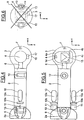
- the underwater vehicle comprises a front body 1 of generally cylindrical shape, and having a front end of generally hemispherical shape, a rear body 2, of generally cylindrical shape, and provided with a rear end 2a of truncated ogival shape a fairing 3 disposed between the front and rear bodies 2, in the general shape of a sphere truncated by two parallel planes equidistant from the center of said sphere and being connected to the front 1 and rear 2 bodies by generally toroidal shaped fillet-type connections, and a pivoting part 4 disposed in the fairing 3 about a longitudinal axis X of the underwater vehicle, lateral axis being noted Y and the axis of the depths or vertical axis being noted Z, according to the normal position of a machine in the water.
- the pivoting part 4 is supported by the front 1 and rear 2 bodies by means of trunnions, respectively 5 and 6.
- One of the two trunnions 5 or 6 is motorized, so that the rotation of the pivoting part 4 is controlled. .
- the pivoting part 4 can pivot more or less 180 ° around the X axis.
- the front body 1 comprises a camera 7 disposed at the hemispherical end made of transparent material to allow automatic guidance or remote control of the underwater vehicle.
- the front body 1 is also provided with a sonar 8 disposed on one side of the cylindrical portion of said front body 1.
- the rear body 2 is provided with a stabilizer 9 fixed at its truncated end ogival end 2a, cruciform and ensuring the stability of the displacement of the underwater vehicle in the water.
- the empennage 9 is fixed relative to the rear body 2.
- the longitudinal propulsion of the underwater vehicle is provided by two longitudinal thrusters 10 fixed on one side and the other of the rear body 2 in front of the empennage 9.
- the thrusters 10 are fixed relative to the rear body 2 and each comprise a cylindrical body 10a rounded at the ends provided with an electric motor and a faired propeller 10b driven by the electric motor of the body 10a and disposed between said body 10a and the empennage 9.
- the thrusters 10 provide the X-axis displacement and orientation of the underwater vehicle in a plane (X, Y), and are symmetrical with respect to a (X, Z) plane.
- the rear body 2 supports two tilting panels 11, arranged at a short distance behind the thrusters 10, to be located in the stream of water stirred by said thrusters 10.
- the tilting panels 11 are also symmetrical with respect to the plane ( X, Z) and allow orientation of the underwater vehicle towards the surface or on the contrary towards the seabed.
- the tilting panels 11 form elevators and pivot about an axis parallel to the Y axis, by means of actuators (not shown) arranged in the rear body 2.
- the vertical thrusters 12 and 13 allow the vehicle under -Marine to move along the Z axis, even in the absence of displacement along the X axis.
- the vertical thrusters 12 and 13 are well adapted to ensure the fine positioning of the submarine vehicle near an object in front of be identified and / or destroyed.
- the pivoting part 4, disposed in the fairing 3, has a shape of revolution with a substantially hemispherical head 4a, see figure 2 , a substantially cylindrical central portion 4b, and a flat rear portion 4c and connected to the central portion 4b by connecting fillet. Thanks to the journals 5 and 6, the pivoting part 4 can move in rotation about the axis X.
- a camera 14 is disposed in the front part 4a and an explosive charge 15, hollow charge type, is arranged in the central part. 4b and provided to deliver the energy of the explosion to the front portion 4a of the pivoting portion 4.
- the camera 14 and the explosive charge 15 are oriented substantially coaxially forward of the pivoting portion 4.
- the observation by the camera 14 and the destruction of a suspicious object can be performed in a plane transverse to the longitudinal axis X of the underwater vehicle.
- the orientation in a transverse plane of the pivoting part 4 makes it possible to tackle a suspicious object from above, by orienting the pivoting part 4 downwards, from below, by orienting the pivoting part 4 upwards as illustrated on FIG. figure 2 , which may be interesting in the caine mine orin, or by the side by orienting the pivoting part 4 on one side or the other of the underwater vehicle.
- all intermediate oblique orientations are possible.
- the fairing 3 is made of optically transparent material, so that the camera can observe an object which is in the vicinity of the underwater vehicle.
- the diameter of the fairing 3 may be greater than that of the rear body 2.
- the fairing 3 may be made of a transparent synthetic material, such as plexiglass, and is pierced with one or more holes 16 to allow its filling by the water when launching the submarine vehicle. It is thus possible to use a fairing 3 of small thickness which is not very resistant to the pressure exerted by the water and therefore of low mass, inexpensive and does not interfere with the optical observation or the effects of the explosion on the object. suspect.
- the underwater vehicle is also provided with an acoustic sensor 17, for example a sonar, supported by the central portion 4b of the pivoting part 4. It thus promotes the detection and location of the suspect object and the positioning end of the underwater vehicle with respect to the suspect object, especially in murky waters, for example loaded with sediments.
- the acoustic waves are transmitted by the water which is in the fairing 3, and by the fairing 3 made of acoustically transparent material.
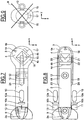
- the embodiment illustrated on the Figures 4 to 6 differs from the previous one in that the underwater vehicle is devoid of front body and associated sonar.
- the fairing 3 forms the front end of the underwater vehicle and is in the form of a truncated sphere on the rear side by a plane transverse to the longitudinal axis X and connecting to the rear body 2 by a connecting fillet of general toroidal shape.
- the pivoting part 4 is pivotally mounted on the single journal 6 secured to the rear body 2.
- the camera 14 and the acoustic sensor 17 allow the underwater vehicle to locate and recognize a suspicious object.
- the camera 7 is attached to the front of the fairing 3 and is oriented forward to provide vision in the direction of navigation.
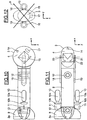
- the embodiment illustrated on the Figures 7 to 9 is closer to the previous by the presence of the fairing 3, forming the front end of the underwater vehicle.
- the underwater vehicle comprises two arms 18 and 19 parallel to the longitudinal axis X, fixed to the rear body 2 and extending partly along the rear body 2 and partly beyond said rear body 2 towards the rear body 2. before.
- the arms 18 and 19 are symmetrical about the plane (X, Z) and each support at their free end a pin 20, 21 on which is articulated the pivoting portion 4.
- the pins 20, 21 are aligned along an axis parallel to the transverse axis Y.
- An actuator 22 housed in the arm 19 makes it possible to control the pivoting position of the pivoting part 4. It can be provided that the part 4 pivots on an angle of at least plus or minus 90 °.
- the camera 14 can be used for viewing in the direction of navigation in the absence of a fixed camera.
- the fairing 3 has, seen from the front, a generally ellipsoidal shape having a height on the Z axis greater than its width on the Y axis and thus allowing the pivoting part 4 to have sufficient space inside. of said fairing 3.
- the portion of the arms 18 and 19 attached to the rear body 2 may also be covered by a fairing portion 23, 24, of profiled shape, providing a lower resistance to advance in the water.
- the portion of the arms 18 and 19 projecting from the rear body 2 is disposed in the fairing 3.
- the pivoting portion 4 can be directed towards the front of the vehicle, so as to detect any obstacles.
- the pivoting part 4 can scan the possible pivot range to increase the probability of detection of a suspicious object.
- the pivoting portion 4 is then inclined to the desired angle ensuring the best probability of destruction according to the shape and characteristics of the suspect object.
- the illustrated embodiment Figures 10 to 12 differs from the previous in that the fairing 3 is fixed integrally to the pivoting part 4 and the fixed part 2 has a connection with the fairing 3 by means of the arms 18 and 19 arranged laterally on either side of the fairing 3
- the shroud 3 has a circular section in section along a plane parallel to the plane (X, Z) and pivots about the Y axis. The hydrodynamics is preserved during rotation. In section along a plane passing through the pivot axis, the fairing 3 is of substantially ellipsoidal shape. The fairing 3 is resistant to pressure and therefore devoid of hole.
- the pivoting portion provided with at least one sensor is disposed inside a fairing so that the pivoting of said pivoting part does not modify the flow. water along its outer walls.
- the hydrodynamics of the underwater vehicle is independent of the orientation of the pivoting part 4. This ensures a precise positioning and easier, avoiding the change of inclination of a projecting member , for example the acoustic sensor 17, does not come to modify the flow of water along the underwater vehicle and obliges to restore the position of the underwater vehicle by an action on the vertical thrusters 12 and 13, on the thrusters longitudinal 10 on the tilting panels 11, or on the pivoting portion 4 itself.
- This advantage is even more important in the case of strong marine currents, which result in a high relative speed of the underwater vehicle with respect to water and a zero or near zero relative speed of the underwater vehicle compared to the sea. suspicious object.
- a modification of the hydrodynamics may cause either an inadvertent removal of the underwater vehicle from the suspect object or a direct impact, which may damage the underwater vehicle without putting the explosive charge under ideal operating conditions, a hollow charge that may require some distance from the target and suspect to destroy to achieve maximum destruction effect.
- the piloting of the underwater vehicle is thus made simpler and the destruction of the suspect object can be conducted more quickly, which results in a significant savings in operating cost, insofar as the ship or the aircraft having dropped the underwater vehicle for the purpose of destroying the suspect object, it generally remains near the area where the suspect object is located until it is destroyed.
Landscapes
- Engineering & Computer Science (AREA)
- Chemical & Material Sciences (AREA)
- Combustion & Propulsion (AREA)
- General Engineering & Computer Science (AREA)
- Aviation & Aerospace Engineering (AREA)
- Measurement Of Velocity Or Position Using Acoustic Or Ultrasonic Waves (AREA)
- Earth Drilling (AREA)
- Bidet-Like Cleaning Device And Other Flush Toilet Accessories (AREA)
- Toys (AREA)
Claims (16)
- Verbrauchbare Unterwasservorrichtung zur Zerstörung von Grundminen oder Ankertauminen, die einen ersten Teil (2), der mit Antriebseinrichtungen versehen ist, und einen zweiten Teil (4) enthält, der bezüglich des ersten Teils gemäß mindestens einer Achse schwenken kann, damit die Vorrichtung sich einem Unterwasserobjekt gemäß verschiedenen Ausrichtungen annähern kann, dadurch gekennzeichnet, dass sie eine Verkleidung (3) zum Schutz des zweiten Teils (4) enthält, damit die hydrodynamischen Eigenschaften der Vorrichtung von der Ausrichtung des zweiten Teils (4) bezüglich des ersten Teils (2) unabhängig sind, und dass sie zwei Längstriebwerke, die beiderseits des ersten Teils (2) an der Vorderseite eines festen Leitwerks befestigt sind, und zwei Vertikaltriebwerke umfasst, die in dem ersten Teil angeordnet sind, und zwar das eine in der Nähe der Verkleidung (3) und das andere auf der Höhe des festen Leitwerks.
- Vorrichtung nach Anspruch 1, bei der die Verkleidung wasserdurchlässig ist.
- Vorrichtung nach Anspruch 1, bei der die Verkleidung eine Schale bildet, die gegenüber dem hydrostatischen Druck fest ist.
- Vorrichtung nach einem der vorhergehenden Ansprüche, die Einrichtungen zum Schwenken des zweiten Teils bezüglich des ersten Teils enthält, wobei die Schwenkeinrichtungen mit mindestens einem Motor versehen sind.
- Vorrichtung nach einem der Ansprüche 1 bis 4, bei der die Schwenkachse eine Querachse ist.
- Vorrichtung nach einem der Ansprüche 1 bis 4, bei der die Schwenkachse eine Längsachse ist.
- Vorrichtung nach einem der Ansprüche 1 bis 4, bei der die Schwenkachse senkrecht ist.
- Vorrichtung nach einem der Ansprüche 1 bis 4, bei der das Schwenken um zwei Achsen erfolgt.
- Vorrichtung nach einem der vorhergehenden Ansprüche, bei der die Verkleidung (3) im Wesentlichen akustisch transparent ist.
- Vorrichtung nach einem der vorhergehenden Ansprüche, bei der die Verkleidung (3) im Wesentlichen optisch transparent ist.
- Vorrichtung nach einem der vorhergehenden Ansprüche, bei der die Verkleidung (3) am ersten Teil (2) befestigt ist.
- Vorrichtung nach Anspruch 11, bei der die Verkleidung (3) an der Vorderseite des ersten Teils (2) befestigt ist.
- Vorrichtung nach Anspruch 11, bei der die Verkleidung im Wesentlichen in der Mitte des ersten Teils befestigt ist.
- Vorrichtung nach einem der Ansprüche 1 bis 10, bei der die Verkleidung am zweiten Teil befestigt ist.
- Vorrichtung nach einem der vorhergehenden Ansprüche, bei der die Verkleidung eine Drehsymmetrie bezüglich der Schwenkachse aufweist.
- Vorrichtung nach einem der vorhergehenden Ansprüche, bei der der zweite Teil mindestens eine Einrichtung zur Beobachtung von Unterwasserobjekten und/oder mindestens eine Einrichtung zur Identifizierung von Unterwasserobjekten und/oder mindestens eine Einrichtung zur Lokalisierung eines Unterwasserobjekts und/oder mindestens eine Einrichtung zum Schätzen der Entfernung bezüglich des Unterwasserobjekts und/oder mindestens eine Einrichtung zur Klassifizierung von Unterwasserobjekten und/oder mindestens eine Angriffseinrichtung enthält.
Priority Applications (1)
| Application Number | Priority Date | Filing Date | Title |
|---|---|---|---|
| PL04805232T PL1794049T5 (pl) | 2004-09-29 | 2004-09-29 | Urządzenie do niszczenia obiektów podwodnych lub pływających |
Applications Claiming Priority (1)
| Application Number | Priority Date | Filing Date | Title |
|---|---|---|---|
| PCT/FR2004/002466 WO2006035121A1 (fr) | 2004-09-29 | 2004-09-29 | Dispositif de destruction d'objets sous-marins ou flottants |
Publications (3)
| Publication Number | Publication Date |
|---|---|
| EP1794049A1 EP1794049A1 (de) | 2007-06-13 |
| EP1794049B1 EP1794049B1 (de) | 2010-06-16 |
| EP1794049B2 true EP1794049B2 (de) | 2017-06-07 |
Family
ID=34960236
Family Applications (1)
| Application Number | Title | Priority Date | Filing Date |
|---|---|---|---|
| EP04805232.8A Active EP1794049B2 (de) | 2004-09-29 | 2004-09-29 | Vorrichtung zum ablenken von unterwasser- oder schwimmobjekten |
Country Status (6)
| Country | Link |
|---|---|
| US (1) | US7752990B2 (de) |
| EP (1) | EP1794049B2 (de) |
| DE (1) | DE602004027765D1 (de) |
| NO (1) | NO339860B1 (de) |
| PL (1) | PL1794049T5 (de) |
| WO (1) | WO2006035121A1 (de) |
Families Citing this family (6)
| Publication number | Priority date | Publication date | Assignee | Title |
|---|---|---|---|---|
| DE102010033638A1 (de) * | 2010-08-06 | 2012-02-09 | Atlas Elektronik Gmbh | Kampfmittelräumgerät zum Räumen von Kampfmitteln, wie Seeminen, unter Wasser, unbemanntes Unterwasserfahrzeug mit derartigem Kampfmittelräumgerät sowie Verfahren hierzu |
| FR2969573B1 (fr) | 2010-12-23 | 2013-02-08 | Eca | Dispositif de mise a l'eau et de recuperation d'un engin submersible ou de surface. |
| DE102011018304A1 (de) * | 2011-02-15 | 2012-08-16 | Atlas Elektronik Gmbh | Unbemanntes Unterwasserfahrzeug, daran fixierbarer Austauschkörper, System mit dem unbemannten Unterwasserfahrzeug und dem Austauschkörper sowie Verfahren zum Betreiben eines unbemannten Unterwasserfahrzeugs |
| DE102011121856A1 (de) * | 2011-12-21 | 2013-06-27 | Atlas Elektronik Gmbh | Kampfmittelräumgerät zum Räumen von Kampfmitteln, wie Seeminen, unter Wasser, Kampfmittelräumkombination mit unbemanntem Unterwasserfahrzeug und derartigem Kampfmittelräumgerät sowie Verfahren hierzu. |
| DE102012006566A1 (de) * | 2012-03-30 | 2013-10-02 | Atlas Elektronik Gmbh | Verfahren zur Detektion von Seeminen und Seeminendetektionssystem |
| CN110217362B (zh) * | 2019-05-08 | 2020-05-29 | 上海海事大学 | 一种子母式逃逸型载人潜水器 |
Citations (9)
| Publication number | Priority date | Publication date | Assignee | Title |
|---|---|---|---|---|
| US3448710A (en) † | 1967-05-04 | 1969-06-10 | Thomas Gaskins | Propelling and steering device |
| US3604661A (en) † | 1969-09-25 | 1971-09-14 | Robert Alfred Mayer Jr | Boundary layer control means |
| DE3605579C1 (en) † | 1986-02-21 | 1987-05-07 | Messerschmitt Boelkow Blohm | Missile for attacking targets underneath the flight path (trajectory) of the missile |
| US4992999A (en) † | 1966-07-28 | 1991-02-12 | The United States Of America As Represented By The Secretary Of The Navy | Submarine drone for carrying a barrel stave-type transducer array |
| DE3927724A1 (de) † | 1989-08-23 | 1993-02-25 | Nord Systemtechnik | Unterwasserfahrzeug |
| DE19516341A1 (de) † | 1995-05-04 | 1996-11-07 | Rheinmetall Ind Ag | Flugkörper mit einem schwenkbaren Gefechtskopf |
| DE19813376A1 (de) † | 1998-03-26 | 1999-09-30 | Diehl Stiftung & Co | Gefechtskopf für Flugkörper |
| US20020162515A1 (en) † | 2000-09-06 | 2002-11-07 | Secil Boyd | Support platform and structure for fish farming ("artificial island reef platform") |
| US6606960B1 (en) † | 2001-02-15 | 2003-08-19 | The United States Of America As Represented By The Secretary Of The Navy | SCUBA diver fairing |
Family Cites Families (4)
| Publication number | Priority date | Publication date | Assignee | Title |
|---|---|---|---|---|
| FR2684951A1 (fr) * | 1991-12-17 | 1993-06-18 | Eca | Procede de destruction d'un objet sous-marin, et notamment d'une mine immergee. |
| FR2701918B1 (fr) * | 1993-02-23 | 1995-04-28 | Eca | Procédé perfectionné de destruction d'un objet sous-marin, et notamment d'une mine immergée. |
| GB2305399B (en) * | 1995-09-21 | 1999-05-19 | Marconi Gec Ltd | A submersible mine neutralisation vehicle |
| FR2801274B1 (fr) * | 1999-11-24 | 2001-12-28 | Eca | Dispositif de destruction d'objets sous-marins |
-
2004
- 2004-09-29 WO PCT/FR2004/002466 patent/WO2006035121A1/fr active Application Filing
- 2004-09-29 DE DE200460027765 patent/DE602004027765D1/de active Active
- 2004-09-29 US US11/664,310 patent/US7752990B2/en active Active
- 2004-09-29 PL PL04805232T patent/PL1794049T5/pl unknown
- 2004-09-29 EP EP04805232.8A patent/EP1794049B2/de active Active
-
2007
- 2007-04-26 NO NO20072156A patent/NO339860B1/no unknown
Patent Citations (9)
| Publication number | Priority date | Publication date | Assignee | Title |
|---|---|---|---|---|
| US4992999A (en) † | 1966-07-28 | 1991-02-12 | The United States Of America As Represented By The Secretary Of The Navy | Submarine drone for carrying a barrel stave-type transducer array |
| US3448710A (en) † | 1967-05-04 | 1969-06-10 | Thomas Gaskins | Propelling and steering device |
| US3604661A (en) † | 1969-09-25 | 1971-09-14 | Robert Alfred Mayer Jr | Boundary layer control means |
| DE3605579C1 (en) † | 1986-02-21 | 1987-05-07 | Messerschmitt Boelkow Blohm | Missile for attacking targets underneath the flight path (trajectory) of the missile |
| DE3927724A1 (de) † | 1989-08-23 | 1993-02-25 | Nord Systemtechnik | Unterwasserfahrzeug |
| DE19516341A1 (de) † | 1995-05-04 | 1996-11-07 | Rheinmetall Ind Ag | Flugkörper mit einem schwenkbaren Gefechtskopf |
| DE19813376A1 (de) † | 1998-03-26 | 1999-09-30 | Diehl Stiftung & Co | Gefechtskopf für Flugkörper |
| US20020162515A1 (en) † | 2000-09-06 | 2002-11-07 | Secil Boyd | Support platform and structure for fish farming ("artificial island reef platform") |
| US6606960B1 (en) † | 2001-02-15 | 2003-08-19 | The United States Of America As Represented By The Secretary Of The Navy | SCUBA diver fairing |
Also Published As
| Publication number | Publication date |
|---|---|
| PL1794049T3 (pl) | 2010-10-29 |
| NO20072156L (no) | 2007-06-27 |
| EP1794049B1 (de) | 2010-06-16 |
| EP1794049A1 (de) | 2007-06-13 |
| DE602004027765D1 (de) | 2010-07-29 |
| US7752990B2 (en) | 2010-07-13 |
| US20080127876A1 (en) | 2008-06-05 |
| NO339860B1 (no) | 2017-02-06 |
| WO2006035121A1 (fr) | 2006-04-06 |
| PL1794049T5 (pl) | 2018-05-30 |
Similar Documents
| Publication | Publication Date | Title |
|---|---|---|
| EP0787095B1 (de) | Verfahren und vorrichtung zur vernichtung von unterwassergegenständen, insbesondere von seeminen | |
| EP2551185B1 (de) | Wasser- oder Unterwassergerät und entsprechendes Ankoppelungsverfahren | |
| CA2997512C (en) | Tow body arrangement for a towable device in a sonar system | |
| EP1794049B2 (de) | Vorrichtung zum ablenken von unterwasser- oder schwimmobjekten | |
| US6095078A (en) | Submarine propulsion control system | |
| EP0547937B1 (de) | Verfahren zur Zerstörung eines Unterwassergegenstandes, insbesondere einer Seemine | |
| EP1147045B1 (de) | Vorrichtung zum zerstören von unterwasserobjekten | |
| FR2679023A1 (fr) | Procede et dispositif pour combattre un objectif immerge. | |
| US6058847A (en) | Submersible mine neutralisation vehicle | |
| EP3906188B1 (de) | Andockvorrichtung für ein unterwasserfahrzeug | |
| EP4363306A1 (de) | Aufrichtvorrichtung für ein unterwasserfahrzeug | |
| EP1582455B1 (de) | Vorrichtung zum Beobachten von unterwasser befindliche Gegenstände | |
| EP0347288B1 (de) | Unterwasserfahrzeug mit eigenem Antrieb für Auffindung versunkener Gegenstände | |
| WO2010119195A1 (fr) | Périscope flottant notamment pour un engin sous-marin | |
| EP0847361B1 (de) | Unterwasserantriebssystem | |
| EP0467765B1 (de) | Verfahren und System um unter einem Hubschrauber im Wasser schleppend zu messen | |
| EP3999801B1 (de) | Geschossabschussdetektor sowie zugehöriges geschoss und abschussanordnung | |
| EP2322420B1 (de) | Oberflächenwasserfahrzeug mit schwenkbarem Tragarm.für Instrumente. | |
| WO2019120928A1 (fr) | Vehicule apte a etre immerge comprenant un mat | |
| FR2668446A1 (fr) | Perfectionnements apportes aux engins sous-marins filo-guides. | |
| WO2023175264A1 (fr) | Véhicule tracté sous-marin et système de récupération d'un tel véhicule sous-marin |
Legal Events
| Date | Code | Title | Description |
|---|---|---|---|
| PUAI | Public reference made under article 153(3) epc to a published international application that has entered the european phase |
Free format text: ORIGINAL CODE: 0009012 |
|
| 17P | Request for examination filed |
Effective date: 20070312 |
|
| AK | Designated contracting states |
Kind code of ref document: A1 Designated state(s): DE FR GB IT PL |
|
| DAX | Request for extension of the european patent (deleted) | ||
| RBV | Designated contracting states (corrected) |
Designated state(s): DE FR GB IT PL |
|
| 17Q | First examination report despatched |
Effective date: 20090505 |
|
| GRAP | Despatch of communication of intention to grant a patent |
Free format text: ORIGINAL CODE: EPIDOSNIGR1 |
|
| GRAS | Grant fee paid |
Free format text: ORIGINAL CODE: EPIDOSNIGR3 |
|
| GRAA | (expected) grant |
Free format text: ORIGINAL CODE: 0009210 |
|
| AK | Designated contracting states |
Kind code of ref document: B1 Designated state(s): DE FR GB IT PL |
|
| REF | Corresponds to: |
Ref document number: 602004027765 Country of ref document: DE Date of ref document: 20100729 Kind code of ref document: P |
|
| REG | Reference to a national code |
Ref country code: PL Ref legal event code: T3 |
|
| PLBI | Opposition filed |
Free format text: ORIGINAL CODE: 0009260 |
|
| PLAX | Notice of opposition and request to file observation + time limit sent |
Free format text: ORIGINAL CODE: EPIDOSNOBS2 |
|
| 26 | Opposition filed |
Opponent name: ATLAS ELEKTRONIK GMBH Effective date: 20110316 |
|
| REG | Reference to a national code |
Ref country code: DE Ref legal event code: R026 Ref document number: 602004027765 Country of ref document: DE Effective date: 20110316 |
|
| PLBB | Reply of patent proprietor to notice(s) of opposition received |
Free format text: ORIGINAL CODE: EPIDOSNOBS3 |
|
| REG | Reference to a national code |
Ref country code: GB Ref legal event code: 732E Free format text: REGISTERED BETWEEN 20121101 AND 20121107 |
|
| PLAB | Opposition data, opponent's data or that of the opponent's representative modified |
Free format text: ORIGINAL CODE: 0009299OPPO |
|
| REG | Reference to a national code |
Ref country code: DE Ref legal event code: R081 Ref document number: 602004027765 Country of ref document: DE Owner name: ECA ROBOTICS, FR Free format text: FORMER OWNER: SOCIETE ECA, LA GARDE, FR Effective date: 20130215 Ref country code: DE Ref legal event code: R082 Ref document number: 602004027765 Country of ref document: DE Representative=s name: CASALONGA & PARTNERS, DE Effective date: 20130215 |
|
| PLAY | Examination report in opposition despatched + time limit |
Free format text: ORIGINAL CODE: EPIDOSNORE2 |
|
| R26 | Opposition filed (corrected) |
Opponent name: ATLAS ELEKTRONIK GMBH Effective date: 20110316 |
|
| PLAB | Opposition data, opponent's data or that of the opponent's representative modified |
Free format text: ORIGINAL CODE: 0009299OPPO |
|
| R26 | Opposition filed (corrected) |
Opponent name: ATLAS ELEKTRONIK GMBH Effective date: 20110316 |
|
| PLBC | Reply to examination report in opposition received |
Free format text: ORIGINAL CODE: EPIDOSNORE3 |
|
| REG | Reference to a national code |
Ref country code: FR Ref legal event code: PLFP Year of fee payment: 12 |
|
| REG | Reference to a national code |
Ref country code: FR Ref legal event code: PLFP Year of fee payment: 13 |
|
| PUAH | Patent maintained in amended form |
Free format text: ORIGINAL CODE: 0009272 |
|
| STAA | Information on the status of an ep patent application or granted ep patent |
Free format text: STATUS: PATENT MAINTAINED AS AMENDED |
|
| 27A | Patent maintained in amended form |
Effective date: 20170607 |
|
| AK | Designated contracting states |
Kind code of ref document: B2 Designated state(s): DE FR GB IT PL |
|
| REG | Reference to a national code |
Ref country code: DE Ref legal event code: R102 Ref document number: 602004027765 Country of ref document: DE |
|
| PUAH | Patent maintained in amended form |
Free format text: ORIGINAL CODE: 0009272 |
|
| STAA | Information on the status of an ep patent application or granted ep patent |
Free format text: STATUS: PATENT MAINTAINED AS AMENDED |
|
| REG | Reference to a national code |
Ref country code: FR Ref legal event code: PLFP Year of fee payment: 14 |
|
| REG | Reference to a national code |
Ref country code: FR Ref legal event code: PLFP Year of fee payment: 15 |
|
| PGFP | Annual fee paid to national office [announced via postgrant information from national office to epo] |
Ref country code: IT Payment date: 20230908 Year of fee payment: 20 Ref country code: GB Payment date: 20230809 Year of fee payment: 20 |
|
| PGFP | Annual fee paid to national office [announced via postgrant information from national office to epo] |
Ref country code: PL Payment date: 20230818 Year of fee payment: 20 Ref country code: FR Payment date: 20230927 Year of fee payment: 20 Ref country code: DE Payment date: 20230911 Year of fee payment: 20 |