EP1790937B1 - Verfahren zur Erhöhung der Ersttrefferwahrscheinlichkeit einer ballistischen Waffe - Google Patents
Verfahren zur Erhöhung der Ersttrefferwahrscheinlichkeit einer ballistischen Waffe Download PDFInfo
- Publication number
- EP1790937B1 EP1790937B1 EP06011919.5A EP06011919A EP1790937B1 EP 1790937 B1 EP1790937 B1 EP 1790937B1 EP 06011919 A EP06011919 A EP 06011919A EP 1790937 B1 EP1790937 B1 EP 1790937B1
- Authority
- EP
- European Patent Office
- Prior art keywords
- weapon
- velocity
- projectile
- flight
- time
- Prior art date
- Legal status (The legal status is an assumption and is not a legal conclusion. Google has not performed a legal analysis and makes no representation as to the accuracy of the status listed.)
- Revoked
Links
- 238000000034 method Methods 0.000 title claims description 18
- 230000007613 environmental effect Effects 0.000 claims description 12
- 239000000843 powder Substances 0.000 claims description 9
- 230000008859 change Effects 0.000 claims description 7
- 241001057440 Didion Species 0.000 claims description 5
- JYGLAHSAISAEAL-UHFFFAOYSA-N Diphenadione Chemical compound O=C1C2=CC=CC=C2C(=O)C1C(=O)C(C=1C=CC=CC=1)C1=CC=CC=C1 JYGLAHSAISAEAL-UHFFFAOYSA-N 0.000 claims description 5
- 230000001131 transforming effect Effects 0.000 claims 1
- 230000009466 transformation Effects 0.000 description 5
- 230000001419 dependent effect Effects 0.000 description 3
- 238000004519 manufacturing process Methods 0.000 description 2
- NIOPZPCMRQGZCE-WEVVVXLNSA-N 2,4-dinitro-6-(octan-2-yl)phenyl (E)-but-2-enoate Chemical compound CCCCCCC(C)C1=CC([N+]([O-])=O)=CC([N+]([O-])=O)=C1OC(=O)\C=C\C NIOPZPCMRQGZCE-WEVVVXLNSA-N 0.000 description 1
- 240000006829 Ficus sundaica Species 0.000 description 1
- 230000008901 benefit Effects 0.000 description 1
- 230000000694 effects Effects 0.000 description 1
- 230000008092 positive effect Effects 0.000 description 1
- 230000008569 process Effects 0.000 description 1
- 230000004044 response Effects 0.000 description 1
- 230000009897 systematic effect Effects 0.000 description 1
- 230000008685 targeting Effects 0.000 description 1
- XLYOFNOQVPJJNP-UHFFFAOYSA-N water Substances O XLYOFNOQVPJJNP-UHFFFAOYSA-N 0.000 description 1
Images


Classifications
-
- F—MECHANICAL ENGINEERING; LIGHTING; HEATING; WEAPONS; BLASTING
- F41—WEAPONS
- F41G—WEAPON SIGHTS; AIMING
- F41G5/00—Elevating or traversing control systems for guns
- F41G5/14—Elevating or traversing control systems for guns for vehicle-borne guns
- F41G5/24—Elevating or traversing control systems for guns for vehicle-borne guns for guns on tanks
-
- F—MECHANICAL ENGINEERING; LIGHTING; HEATING; WEAPONS; BLASTING
- F41—WEAPONS
- F41G—WEAPON SIGHTS; AIMING
- F41G3/00—Aiming or laying means
- F41G3/08—Aiming or laying means with means for compensating for speed, direction, temperature, pressure, or humidity of the atmosphere
-
- F—MECHANICAL ENGINEERING; LIGHTING; HEATING; WEAPONS; BLASTING
- F41—WEAPONS
- F41G—WEAPON SIGHTS; AIMING
- F41G3/00—Aiming or laying means
- F41G3/12—Aiming or laying means with means for compensating for muzzle velocity or powder temperature with means for compensating for gun vibrations
-
- F—MECHANICAL ENGINEERING; LIGHTING; HEATING; WEAPONS; BLASTING
- F41—WEAPONS
- F41G—WEAPON SIGHTS; AIMING
- F41G3/00—Aiming or laying means
- F41G3/22—Aiming or laying means for vehicle-borne armament, e.g. on aircraft
Definitions
- the invention relates to a method for increasing the first hit probability of a ballistic weapon.
- the projectile In the case of weapons in which a projectile is fired from a pipe, the projectile describes a trajectory that depends on the velocity of the projectile and the position of the pipe. Especially with long ranges and / or the use of temporary ammunition, an exact calculation of this trajectory is essential for the targeting process.
- cross wind which occurs perpendicular to the direction of flight of the projectile, by determining a lead, the lateral deviation from the line of sight or sighting, on the basis of approximate calculations or tables in the form of shooting boards.
- the strength of the cross wind is set manually or measured by sensors and determined from a cross wind table, the lead.
- the spin of the projectile enters into the determination of the lead.
- Moving weapon platforms have so far stabilized sight and weapon. It is also known to use pointing aids to aid in tracking goals.
- the DE 26 25 667 A1 shows a fire control system, which takes into account the proper movement of the weapon to determine the lead angle. This is used to create directional signals which a gunner should still optimize or correct.
- the GB 2,159,609 A also shows a guidance system in which the self-movement of the weapon is used to generate an electronically generated target signal in a viewing device.
- the object of the present invention to provide a method with which the first hit probability of a ballistic weapon can be increased.
- the proper movement of the weapon is taken into account.
- environmental conditions such as air temperature or pressure and ammunition parameters such as powder temperature or change in initial velocity are taken into account.
- the powder temperature refers to the temperature of the powder before ignition and the change in the initial speed caused by manufacturing tolerances and / or wear of the pipe deviation from the nominal velocity of the projectile, which is adjustable or measurable.
- the initial velocity of the projectile relative to the weapon is advantageously superimposed three-dimensionally with the weapon's own velocity.
- the vector of the intrinsic speed of the weapon is preferably transformed into a coordinate system based on the tube of the weapon.
- the proper motion of the weapon carrier in the calculation of Vorhalt, essay and time of flight of the projectile is thus fully or graduated in the calculation of the outgoing and outgoing ballistics considered.
- the advance and / or attachment and / or time of flight of the projectile are determined iteratively from the airspeed and position of the weapon. If, for example, a lead is determined, this alters the orientation of the weapon with respect to its own velocity and thus the position of the coordinate system related to the tube of the weapon. On this basis, the lead is determined again and based on the next iteration step.
- the weapon is tracked during the iterative determination, resulting in a quick positioning of the weapon. Alternatively, the iteration may be performed until it is sufficiently converged to then align the weapon with the result.
- the actual initial velocity of the projectile is determined in a first step. This is done in response to one or more of nominal initial velocity, initial velocity change, and powder temperature parameters.
- the nominal initial velocity is the bullet velocity indicated by the munitions manufacturer. Manufacturing tolerances lead to batch-dependent or batch-dependent fluctuations, which can be taken into account as changes in the initial velocity.
- the powder temperature can be further considered. This is the temperature the powder before the ignition, so essentially to the last storage temperature.
- the time of flight of the projectile is determined as a function of the initial speed or the initial speed and prevailing environmental conditions.
- the prevailing environmental conditions may be, for example, the air temperature, the air pressure or the strength of the backwind or headwind.
- other parameters such as the tube position and the position of the target relative to the weapon, z. B. a height difference, are taken into account.
- the required derivative is then calculated using the Didion equation of transverse wind velocity v q , time of flight T, target distance R and initial velocity v 0 of the projectile.
- the lead is not determined from transverse wind tables, as hitherto, but taken into account by means of time tables, the environmental influences and / or ammunition parameters.
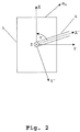
- a weapon 6 (s. FIG. 2 ) mounted in a turret on the tub 5 of a tank as a system or Georgemie.
- the tank moves with a velocity vector v w .
- v w In a Cartesian coordinate system related to the tub 5, the X-axis in the forward direction of the tank, the Y-axis to the right and the Z-axis down.
- the turret and thus the tube 6 of the weapon is rotated in the XY plane by the angle ⁇ to the X-axis.
- the tube 6 has an elevation of the angle ⁇ from the XY plane.
- FIG. 1 illustrated Feuerleitrechner 4 used.
- This receives as input parameters, inter alia, the X, Y and Z components of the velocity vector v W. These components are subjected to a transformation before being supplied to the arithmetic unit 3.
- the transformation transforms the components into a Cartesian coordinate system, which is related to the tube of the weapon.
- the axis X “corresponds to the tube bore axis.
- a rotation about the angle ⁇ around the Z-axis is first made in the element designated by ⁇ .
- the result is an intermediate coordinate system with the axes X ', Y' and Z.
- the angle ⁇ can be changed by the fire control computer 4 and is therefore known this.
- the weapon can be aligned by the control system 2.
- inventive method is not limited to use in tanks. Rather, it is transferable to all types of weapons for land, air and water vehicles.
- the method is only knowledge of the velocity vector v W of the weapon carrier and the angle ⁇ and ⁇ between weapon and weapon carrier necessary.
- 10 designates the weapon, 11 the target and 9 the direct line of sight between weapon 10 and target 11. Due to the cross wind 7, a shot fired in the direction of the sighting line 9 would miss the target 11. It must therefore be targeted in the direction 8, which deviates from the sighting line 9 by the advance angle ⁇
- the initial velocity of the projectile is first determined as a function of one or more of the parameters nominal initial velocity, change of the initial velocity and powder temperature. This is done by means of relevant tables or an approximate or exact calculation. From this initial velocity v 0 , the flight time of the projectile is determined in a second step. In determining the flight time, the prevailing environmental conditions, such. As air temperature, air pressure or backwind or headwind, be included. Also geometric conditions, such as the distance to the target or a height difference between weapon and target, are taken into account. From the above-mentioned Didion equation, a derivative ⁇ 'is calculated taking into account the transverse wind velocity v q , the time of flight T, the target distance R and the initial velocity vo of the projectile. The derivative ⁇ to be set now corresponds to the arctangent of ⁇ '. For small ⁇ 'in radians the approximation ⁇ ⁇ ⁇ ' applies. In addition, the spin deviation of the projectile is taken into account.
- the nominal initial velocity of the projectile is 1000 m / s with a flight time of 2.5 s.
- transverse wind tables are used instead of the method according to the invention, the nominal values for initial speed and flight time result in a lead of 0.1432 degrees or 2.546. At 2000 meters from the weapon, this difference leads to a deviation of 1.57 meters. A correspondingly small target would thus be missed in the determination of the attitude using crosswind tables.
- the compensation of the proper movement of the weapon and the consideration of environmental conditions and ammunition parameters in the determination of advance and / or attachment can be used both separately and in combination.
Landscapes
- Engineering & Computer Science (AREA)
- General Engineering & Computer Science (AREA)
- Aviation & Aerospace Engineering (AREA)
- Aiming, Guidance, Guns With A Light Source, Armor, Camouflage, And Targets (AREA)
Description
- Die Erfindung betrifft ein Verfahren zur Erhöhung der Ersttrefferwahrscheinlichkeit einer ballistischen Waffe.
- Bei Waffen, bei denen ein Geschoss aus einem Rohr abgefeuert wird, beschreibt das Geschoss eine Flugbahn, die von der Geschwindigkeit des Geschosses sowie der Rohrstellung abhängig ist. Besonders bei großen Reichweiten und/oder dem Einsatz tempierbarer Munition ist eine exakte Berechnung dieser Flugbahn für den Zielvorgang unerlässlich.
- Bislang ist es üblich, Querwind, der senkrecht zur Flugrichtung des Geschosses auftritt, zu berücksichtigen, indem anhand von approximativen Berechnungen oder Tabellenwerken in Form von Schusstafeln ein Vorhalt, die seitliche Abweichung von der Sicht- bzw. Visierlinie, bestimmt wird. Dabei wird die Stärke des Querwindes manuell eingestellt oder durch Sensoren gemessen und aus einer Querwindtabelle der Vorhalt bestimmt. Ebenfalls geht der Drall des Geschosses in die Bestimmung des Vorhaltes ein. Bei bewegten Waffenplattformen erfolgt bislang eine Stabilisierung von Sichtmitteln und Waffe. Auch ist es bekannt, Richthilfen zur Unterstützung beim Verfolgen von Zielen zu verwenden.
- Die
DE 26 25 667 A1 zeigt hierzu ein Feuerleitsystem, welches zur Bestimmung des Vorhaltwinkels die Eigenbewegung der Waffe berücksichtigt. Dies wird zur Erstellung von Richtsignalen verwendet, welche ein Richtschütze noch optimieren bzw. korrigieren soll. - Die
GB 2 159 609 A - Es hat sich gezeigt, dass bei solchen Systemen die Ersttrefferwahrscheinlichkeit oftmals gering ist, da sich systematische Fehler bei der Bestimmung der idealen Werte für Aufsatz, Vorhalt und Flugzeit des Geschosses ergeben. Es ist daher die Aufgabe der vorliegenden Erfindung, ein Verfahren bereitzustellen, mit dem sich die Ersttrefferwahrscheinlichkeit einer ballistischen Waffe erhöhen lässt.
- Gelöst wird diese Aufgabe durch die Merkmale des Patentanspruchs 1. Weitere vorteilhafte Ausgestaltungen sind in den abhängigen Ansprüchen angegeben.
- So wird bei der Bestimmung von Vorhalt und/oder Aufsatz, der Elevation des Waffenrohrs gegenüber der Visierlinie, die Eigenbewegung der Waffe berücksichtigt. Alternativ oder zusätzlich werden Umweltbedingungen wie Lufttemperatur oder Luftdruck und Munitionsparameter wie Pulvertemperatur oder Änderung der Anfangsgeschwindigkeit berücksichtigt. Die Pulvertemperatur bezeichnet dabei die Temperatur des Pulvers vor der Zündung und die Änderung der Anfangsgeschwindigkeit die durch Fertigungstoleranzen und/oder Verschleiß des Rohres hervorgerufene Abweichung von der Nominalgeschwindigkeit des Geschosses, die einstellbar oder messbar ist.
- Bei der Berücksichtigung der Eigenbewegung der Waffe wird in vorteilhafter Weise die Anfangsgeschwindigkeit des Geschosses relativ zur Waffe, also bezogen auf das Waffenrohr, dreidimensional mit der Eigengeschwindigkeit des Waffenträgers überlagert. Dazu wird bevorzugt der Vektor der Eigengeschwindigkeit der Waffe in ein auf das Rohr der Waffe bezogenes Koordinatensystem transformiert. Die Eigenbewegung des Waffenträgers bei der Berechnung von Vorhalt, Aufsatz und Flugzeit des Geschosses wird somit vollständig oder abgestuft bei der Berechnung der Abgangs- und Außenballistik berücksichtigt.
- Aus den Bewegungskomponenten quer zur Geschossgeschwindigkeit, bezogen auf ein waffenorientiertes Koordinatensystem, resultieren die notwendigen Änderungen der Abgangswinkel. Die Änderung der Geschossgeschwindigkeit in Richtung der Rohrseelenachse bewirkt Änderungen von Aufsatz, Vorhalt und Flugzeit des Geschosses in Bezug auf die Außenballistik. Daraus folgen Änderungen des dynamischen Aufsatzes und Vorhaltes bei beweglichen Zielen beziehungsweise der Programmierzeit bei tempierbarer Munition, was sich besonders im Modus Luftsprengpunkt positiv auf die Wirkung der Munition auswirkt.
- In vorteilhafter Weise werden Vorhalt und/oder Aufsatz und/oder Flugzeit des Geschosses iterativ aus Eigengeschwindigkeit und Stellung der Waffe bestimmt. Wird beispielsweise ein Vorhalt bestimmt, so ändert dies die Ausrichtung der Waffe in Bezug auf ihre Eigengeschwindigkeit und somit die Lage des auf das Rohr der Waffe bezogenen Koordinatensystems. Auf dieser Basis wird erneut der Vorhalt bestimmt und dem nächsten Iterationsschritt zugrundegelegt. Bevorzugt wird die Waffe während der iterativen Bestimmung nachgeführt, wodurch sich eine schnelle Positionierung der Waffe ergibt. Alternativ kann die Iteration durchgeführt werden, bis diese ausreichend konvergiert ist, um die Waffe dann anhand des Ergebnisses auszurichten.
- Bei der Bestimmung von Vorhalt und/oder Aufsatz werden erfindungsgemäß Umweltbedingungen, wie Lufttemperatur oder Luftdruck, und Munitionsparameter, wie Pulvertemperatur oder Änderung der Anfangsgeschwindigkeit, berücksichtigt. Dazu wird in einem ersten Schritt die tatsächliche Anfangsgeschwindigkeit des Geschosses bestimmt. Dies geschieht in Abhängigkeit von einem oder mehreren der Parameter nominelle Anfangsgeschwindigkeit, Änderung der Anfangsgeschwindigkeit und Pulvertemperatur. Bei der nominellen Anfangsgeschwindigkeit handelt es sich um die vom Munitionshersteller angegebene Geschossgeschwindigkeit. Durch Fertigungstoleranzen kommt es zu chargen- bzw. losabhängigen Schwankungen, die als Änderungen der Anfangsgeschwindigkeit berücksichtigt werden können. Bei der Bestimmung der Anfangsgeschwindigkeit kann weiter die Pulvertemperatur berücksichtigt werden. Dabei handelt es sich um die Temperatur des Pulvers vor der Zündung, also im Wesentlichen um die letzte Lagertemperatur.
- In einem zweiten Schritt wird die Flugzeit des Geschosses in Abhängigkeit der Anfangsgeschwindigkeit oder der Anfangsgeschwindigkeit und vorherrschender Umweltbedingungen bestimmt. Bei den vorherrschenden Umweltbedingungen kann es sich beispielsweise um die Lufttemperatur, den Luftdruck oder die Stärke des Rücken- bzw. Gegenwindes handeln. Zusätzlich können weitere Parameter, wie die Rohrstellung und die Position des Ziels relativ zur Waffe, z. B. ein Höhenunterschied, berücksichtigt werden. Der benötigte Vorhalt wird dann mit Hilfe der Didion'schen Gleichung aus Querwindgeschwindigkeit vq, Flugzeit T, Zielentfernung R und Anfangsgeschwindigkeit v0 des Geschosses berechnet. Die Didion'sche Gleichung lautet:

- Durch das erfindungsgemäße Verfahren wird also der Vorhalt nicht wie bislang aus Querwindtabellen bestimmt, sondern anhand von Flugzeittabellen, die Umwelteinflüsse und/oder Munitionsparameter berücksichtigen.
- Die auf die vorstehend beschriebene Art korrigierten Werte für Aufsatz, Vorhalt und Flugzeit werden wie bekannt in Feuerleitrechnern zur Ausrichtung der Waffe in Bezug auf die Sichtlinie eines Beobachtungs- oder Zielgerätes genutzt.
- Die Erfindung soll anhand zweier Ausführungsbeispiele näher erläutert werden. Dabei zeigt:
- Figur 1
- einen Feuerleitrechner,
- Figur 2
- die relative Lager zweier Koordinatensysteme und
- Figur 3
- eine Geometrie zur Bestimmung des Vorhalts.
- In einem ersten Ausführungsbeispiel ist eine Waffe 6 (s.
Figur 2 ) in einem Geschützturm auf der Wanne 5 eines Panzers als System- bzw. Waffenträger montiert. Der Panzer bewegt sich mit einem Geschwindigkeitsvektorv w . Bei einem auf die Wanne 5 bezogenen karthesischen Koordinatensystem zeigt die X-Achse in Vorwärtsrichtung des Panzers, die Y-Achse nach rechts und die Z-Achse nach unten. Der Geschützturm und damit das Rohr 6 der Waffe ist in der XY-Ebene um den Winkel ψ zur X-Achse gedreht. Außerdem weist das Rohr 6 eine Elevation um den Winkel Θ aus der XY-Ebene auf. - Zur Durchführung des erfindungsgemäßen Verfahrens wird der in
Figur 1 dargestellte Feuerleitrechner 4 verwendet. Dieser erhält als Eingangsparameter unter anderem die X-, Y- und Z-Komponente des Geschwindigkeitsvektorsv W . Diese Komponenten werden einer Transformation unterzogen, bevor sie der Rechneneinheit 3 zugeführt werden. Die Transformation überführt die Komponenten in ein ebenfalls karthesisches Koordinatensystem, das auf das Rohr der Waffe bezogen ist. Die Achse X" entspricht dabei der Rohrseelenachse. - Zur Transformation wird in dem mit ψ bezeichneten Element zunächst eine Rotation um den Winkel ψ um die Z-Achse vorgenommen. Es entsteht ein Zwischen-Koordinatensystem mit den Achsen X', Y' und Z. Der Winkel ψ kann durch den Feuerleitrechner 4 verändert werden und ist diesem daher bekannt.
- In dem mit -Θ bezeichneten Element erfolgt eine zweite Rotation, diesmal um den Winkel Θ, den Elevationswinkel des Rohres gegenüber der Visierlinie, um die Y'-Achse. Das Ergebnis ist ein auf das Rohr der Waffe bezogenes Koordinatensystem mit den Achsen X", Y' und Z'. Dies hat den Vorteil, dass zu der X"-Komponente des Geschwindigkeitsvektors
vW die Anfangsgeschwindigkeit v0 des Geschosses bezogen auf die Waffe einfach hinzuaddiert werden kann, um daraus die absolute Anfangsgeschwindigkeit des Geschosses zu bestimmen. Selbstverständlich kann die Transformation des Koordinatensystems auch in einem Schritt erfolgen. - Aus dieser absoluten Anfangsgeschwindigkeit, den anderen Komponenten des Geschwindigkeitsvektors
v W , dem Drall des Geschosses und weiteren, an dieser Stelle nicht näher gekennzeichneten Parametern berechnet die Recheneinheit 3 den Vorhalt und/oder den Aufsatz bezogen auf die nicht dargestellte Visierlinie. Diese Werte werden dem Regelsystem 2 für Waffe und Zielgerät zugeführt. Dieses richtet die Waffe entsprechend aus. Mit den neuen Werten für ψ und Θ wird ein neuer Iterationsschritt, beginnend mit der Transformation des Koordinatensystems, eingeleitet. Durch die veränderte Stellung des Waffenrohres ergibt sich ein neues waffenorientiertes Koordinatensystem. Die in der Recheneinheit 3 bestimmte Flugzeit des Geschosses wird an das Tempiersystem 1 weitergeleitet, um tempierbare Munition mit einem exakten Zündzeitpunkt zu programmieren. - Anstatt die neuen Winkel ψ und Θ bei jedem Iterationsschritt an das Regelsystem 2 weiterzugeben, können diese innerhalb des Feuerleitrechners 4 verbleiben, bis die Iteration ausreichend konvergiert. Erst zu diesem Zeitpunkt kann die Waffe durch das Regelsystem 2 ausgerichtet werden.
- Selbstverständlich ist das erfindungsgemäße Verfahren nicht auf den Einsatz in Panzern beschränkt. Vielmehr ist es auf alle Arten von Waffen für Land-, Luft- und Wasserfahrzeuge übertragbar. Für das Verfahren ist lediglich Kenntnis des Geschwindigkeitsvektors
v W des Waffenträgers sowie der Winkel ψ und Θ zwischen Waffe und Waffenträger notwendig. - Anhand von
Figur 3 wird nun die Berücksichtigung von Umweltbedingungen und Munitionsparametern auf die Bestimmung des Vorhalts erläutert. Dabei bezeichnet 10 die Waffe, 11 das Ziel und 9 die direkte Visierlinie zwischen Waffe 10 und Ziel 11. Aufgrund des Querwindes 7 würde ein in Richtung der Visierlinie 9 abgefeuerter Schuss das Ziel 11 verfehlen. Es muss daher in die Richtung 8 gezielt werden, die um den Vorhaltewinkell η von der Visierlinie 9 abweicht - Dazu wird zunächst die Anfangsgeschwindigkeit des Geschosses in Abhängigkeit eines oder mehrerer der Parameter nomineller Anfangsgeschwindigkeit, Änderung der Anfangsgeschwindigkeit und Pulvertemperatur bestimmt. Dies erfolgt mittels einschlägiger Tabellen oder einer approximativen oder exakten Berechnung. Aus dieser Anfangsgeschwindigkeit v0 wird in einem zweiten Schritt die Flugzeit des Geschosses bestimmt. In die Bestimmung der Flugzeit können weiterhin die vorherrschenden Umweltbedingungen, z. B. Lufttemperatur, Luftdruck oder Rücken- bzw. Gegenwind, einbezogen werden. Auch geometrische Bedingungen, wie der Abstand zum Ziel oder ein Höhenunterschied zwischen Waffe und Ziel, werden berücksichtigt. Aus der oben angegebenen Didion'schen Gleichung wird nun unter Berücksichtigung der Querwindgeschwindigkeit vq, der Flugzeit T, der Zielentfernung R und der Anfangsgeschwindigkeit vo des Geschosses ein Vorhalt η' berechnet. Der einzustellende Vorhalt η entspricht nun dem Arkustangens von η'. Für kleine η' gilt im Bogenmaß die Näherung η ≈ η'. Zusätzlich wird die Drallabweichung des Geschosses berücksichtigt.
- In einem Zahlenbeispiel sei vq = 10 m/s und R = 2000 m. Die nominelle Anfangsgeschwindigkeit des Geschosses betrage 1000 m/s bei einer Flugzeit von 2,5 s. Die tatsächliche Anfangsgeschwindigkeit ergibt sich in Abhängigkeit der oben angebenen Parameter aus entsprechenden Tabellen zu v0 = 1050 m/s, die tatsächliche Flugzeit zu T = 2,25 s. Eingesetzt in die Didion'sche Gleichung führt dies zu η' = 0,00173 oder η = 0,0989 Grad. In Strich ausgedrückt, wobei 6400 Strich einem Vollkreis mit 360 Grad entsprechen, ergibt sich ein Vorhalt von 1,758 Strich. Werden statt des erfindungsgemäßen Verfahrens Querwindtabellen verwendet, so ergibt sich aus den nominellen Werten für Anfangsgeschwindigkeit und Flugzeit ein Vorhalt von 0,1432 Grad oder 2,546 Strich. In 2000 Metern Entfernung von der Waffe führt dieser Unterschied im Vorhalt zu einer Abweichung von 1,57 Metern. Ein entsprechend kleines Ziel würde somit bei der Vorhaltbestimmung anhand von Querwindtabellen verfehlt.
- Welche Umweltbedingungen und Munitionsparameter zur Bestimmung von Vorhalt und/oder Aufsatz verwendet werden, hängt einzig von dem im konkreten Fall zur Verfügung stehenden Schusstafeln bzw. Approximationsgleichungen für die Anfangsgeschwindigkeit und Flugzeit des Geschosses ab.
- Die Kompensation der Eigenbewegung der Waffe und die Berücksichtigung von Umweltbedingungen und Munitionsparametern bei der Bestimmung von Vorhalt und/oder Aufsatz können sowohl separat als auch in Kombination eingesetzt werden.
Claims (9)
- Verfahren zur Erhöhung der Ersttrefferwahrscheinlichkeit einer ballistischen Waffe (10), bei dem bei der Bestimmung von Vorhalt und Aufsatz die Eigenbewegung der Waffe (10) berücksichtigt wird, dadurch gekennzeichnet, dass Munitionsparameter berücksichtigt werden, und dass die Anfangsgeschwindigkeit des Geschosses relativ zur Waffe (10) mit der Eigengeschwindigkeit der Waffe (10) überlagert wird, wobei der Vektor (
v W ) der Eigengeschwindigkeit der Waffe (10) in ein auf das Rohr (6) der Waffe (10) bezogenes Koordinatensystem transformiert wird. - Verfahren nach Anspruch 1, dadurch gekennzeichnet, dass auch Umweltbedingungen wie Lufttemperatur oder Luftdruck berücksichtigt werden.
- Verfahren nach einem der Ansprüche 1 oder 2, dadurch gekennzeichnet, dass Vorhalt und Aufsatz iterativ aus Eigengeschwindigkeit und Stellung der Waffe (10) bestimmt werden.
- Verfahren nach einem der Ansprüche 1 bis 3, dadurch gekennzeichnet, dass die Flugzeit des Geschosses iterativ aus Eigengeschwindigkeit und Stellung der Waffe (10) bestimmt wird.
- Verfahren nach einem der Ansprüche 1 bis 4, dadurch gekennzeichnet, dass die Anfangsgeschwindigkeit des Geschosses in Abhängigkeit eines oder mehrerer der Parameter wie nominelle Anfangsgeschwindigkeit, Änderung der Anfangsgeschwindigkeit bzw. Pulvertemperatur bestimmt wird.
- Verfahren nach Anspruch 5, dadurch gekennzeichnet, dass die Flugzeit des Geschosses in Abhängigkeit von der Anfangsgeschwindigkeit bestimmt wird.
- Verfahren nach Anspruch 5 oder 6, dadurch gekennzeichnet, dass die Flugzeit des Geschosses in Abhängigkeit von vorherrschenden Umweltbedingungen bestimmt wird.
- Verfahren nach einem der Ansprüche 4 oder 6, dadurch gekennzeichnet, dass der Vorhalt mithilfe der Didion'schen Gleichung aus Querwindgeschwindigkeit, Flugzeit, Zielentfernung und Anfangsgeschwindigkeit des Geschosses berechnet wird.
- Feuerleitrechner (4) zur Durchführung des Verfahrens nach einem der Ansprüche 1 bis 8, gekennzeichnet durch Mittel zur Transformation eines Bewegungsvektors einer Waffe in ein auf das Rohr (6) der Waffe (10) bezogenes Koordinatensystem und Mittel zur Bestimmung der Anfangsgeschwindigkeit und der Flugzeit des Geschosses unter Einbeziehung von Umweltbedingungen und Munitionsparametern, wobei mit den Mitteln der Vektor (
v W ) der Eigengeschwindigkeit der Waffe (10) in ein auf das Rohr (6) der Waffe (10) bezogenes Koordinatensystem transformiert wird und die Anfangsgeschwindigkeit des Geschosses relativ zur Waffe (10) mit der Eigengeschwindigkeit der Waffe (10) überlagert wird.
Priority Applications (1)
| Application Number | Priority Date | Filing Date | Title |
|---|---|---|---|
| PL06011919T PL1790937T3 (pl) | 2005-08-18 | 2006-06-09 | Sposób podwyższenia prawdopodobieństwa pierwszego trafienia broni balistycznej |
Applications Claiming Priority (1)
| Application Number | Priority Date | Filing Date | Title |
|---|---|---|---|
| DE102005038979A DE102005038979A1 (de) | 2005-08-18 | 2005-08-18 | Verfahren zur Erhöhung der Ersttrefferwahrscheinlichkeit einer ballistischen Waffe |
Publications (3)
| Publication Number | Publication Date |
|---|---|
| EP1790937A2 EP1790937A2 (de) | 2007-05-30 |
| EP1790937A3 EP1790937A3 (de) | 2007-11-28 |
| EP1790937B1 true EP1790937B1 (de) | 2016-02-17 |
Family
ID=37685902
Family Applications (1)
| Application Number | Title | Priority Date | Filing Date |
|---|---|---|---|
| EP06011919.5A Revoked EP1790937B1 (de) | 2005-08-18 | 2006-06-09 | Verfahren zur Erhöhung der Ersttrefferwahrscheinlichkeit einer ballistischen Waffe |
Country Status (4)
| Country | Link |
|---|---|
| EP (1) | EP1790937B1 (de) |
| DE (1) | DE102005038979A1 (de) |
| ES (1) | ES2568239T3 (de) |
| PL (1) | PL1790937T3 (de) |
Families Citing this family (2)
| Publication number | Priority date | Publication date | Assignee | Title |
|---|---|---|---|---|
| DE102006036257A1 (de) * | 2006-08-03 | 2008-02-07 | Rheinmetall Defence Electronics Gmbh | Bestimmung der einzustellenden Ausrichtung einer ballistischen Waffe |
| DE102013007229A1 (de) | 2013-04-26 | 2014-10-30 | Rheinmetall Waffe Munition Gmbh | Verfahren zum Betrieb eines Waffensystems |
Citations (17)
| Publication number | Priority date | Publication date | Assignee | Title |
|---|---|---|---|---|
| DE1030223B (de) | 1955-09-02 | 1958-05-14 | Siemens Ag Albis | Radaranlage fuer die Leitung von Fliegerabwehrgeschuetzen auf einem Schiff |
| DE1937412A1 (de) | 1968-08-21 | 1970-02-26 | Hughes Aircraft Co | Ballistikrechner |
| DE2625667A1 (de) | 1976-06-08 | 1977-12-22 | Licentia Gmbh | Feuerleitsystem fuer auf einem fahrzeug installierte feuerwaffen mit einem stabilisierten zielgeraet |
| DE2059665C3 (de) | 1970-12-04 | 1978-04-20 | Rheinmetall Gmbh, 4000 Duesseldorf | Verfahren und Anordnung zur Berücksichtigung von Munitionseigenschaften beim Richten eines Geschützes und/ oder beim Einstellen des Zünders der Munition |
| DE2154741B2 (de) | 1971-11-04 | 1979-03-01 | Rheinmetall Gmbh, 4000 Duesseldorf | Verfahren und Anordnung zur Berücksichtigung von Munitionseigenschaften beim Richten eines Geschützes und/oder beim Einstellen des Zünders der Munition |
| DE2601573A1 (de) | 1976-01-16 | 1979-09-27 | Wegmann & Co | Koinzidenzschaltung zum abfeuern einer waffe in einem kampffahrzeug |
| GB2114719A (en) | 1982-02-12 | 1983-08-24 | Marconi Co Ltd | Assessment of weapon fire control systems |
| US4531299A (en) | 1984-03-21 | 1985-07-30 | The United States Of America As Represented By The Secretary Of The Navy | Analog inclination data system |
| GB2159609A (en) | 1977-11-01 | 1985-12-04 | Marconi Co Ltd | Gun sights |
| CH660807A5 (de) | 1982-07-07 | 1987-06-15 | Krupp Gmbh | Digitaler ballistikrechner fuer ein feuerleitsystem einer rohrwaffe. |
| GB2216995A (en) | 1988-04-08 | 1989-10-18 | Marconi Co Ltd | Stabilised weapon system |
| DE3716450C1 (en) | 1987-05-16 | 1990-05-17 | Rheinmetall Gmbh | Setting electronic timer for munition detonator - entering type, temp. of drive charge weather and target data in fuse ignition computer |
| US5448936A (en) | 1994-08-23 | 1995-09-12 | Hughes Aircraft Company | Destruction of underwater objects |
| GB2309770A (en) | 1995-06-01 | 1997-08-06 | Avimo Ltd | Elevation compensating gun sight |
| DE19719977C1 (de) | 1997-05-13 | 1998-10-08 | Industrieanlagen Betriebsges | Video-Visier mit integrierter Feuerleitung für Gewehre |
| WO2006122527A1 (de) | 2005-05-17 | 2006-11-23 | Krauss-Maffei Wegmann Gmbh & Co. Kg | Verfahren zur ermittlung einer feuerleitlösung |
| US7500423B2 (en) | 2003-03-04 | 2009-03-10 | Totalforsvarets Forskningsinstitut | Method of making a projectile in a trajectory act at a desired point at a calculated point of time |
-
2005
- 2005-08-18 DE DE102005038979A patent/DE102005038979A1/de not_active Ceased
-
2006
- 2006-06-09 EP EP06011919.5A patent/EP1790937B1/de not_active Revoked
- 2006-06-09 ES ES06011919.5T patent/ES2568239T3/es not_active Expired - Lifetime
- 2006-06-09 PL PL06011919T patent/PL1790937T3/pl unknown
Patent Citations (17)
| Publication number | Priority date | Publication date | Assignee | Title |
|---|---|---|---|---|
| DE1030223B (de) | 1955-09-02 | 1958-05-14 | Siemens Ag Albis | Radaranlage fuer die Leitung von Fliegerabwehrgeschuetzen auf einem Schiff |
| DE1937412A1 (de) | 1968-08-21 | 1970-02-26 | Hughes Aircraft Co | Ballistikrechner |
| DE2059665C3 (de) | 1970-12-04 | 1978-04-20 | Rheinmetall Gmbh, 4000 Duesseldorf | Verfahren und Anordnung zur Berücksichtigung von Munitionseigenschaften beim Richten eines Geschützes und/ oder beim Einstellen des Zünders der Munition |
| DE2154741B2 (de) | 1971-11-04 | 1979-03-01 | Rheinmetall Gmbh, 4000 Duesseldorf | Verfahren und Anordnung zur Berücksichtigung von Munitionseigenschaften beim Richten eines Geschützes und/oder beim Einstellen des Zünders der Munition |
| DE2601573A1 (de) | 1976-01-16 | 1979-09-27 | Wegmann & Co | Koinzidenzschaltung zum abfeuern einer waffe in einem kampffahrzeug |
| DE2625667A1 (de) | 1976-06-08 | 1977-12-22 | Licentia Gmbh | Feuerleitsystem fuer auf einem fahrzeug installierte feuerwaffen mit einem stabilisierten zielgeraet |
| GB2159609A (en) | 1977-11-01 | 1985-12-04 | Marconi Co Ltd | Gun sights |
| GB2114719A (en) | 1982-02-12 | 1983-08-24 | Marconi Co Ltd | Assessment of weapon fire control systems |
| CH660807A5 (de) | 1982-07-07 | 1987-06-15 | Krupp Gmbh | Digitaler ballistikrechner fuer ein feuerleitsystem einer rohrwaffe. |
| US4531299A (en) | 1984-03-21 | 1985-07-30 | The United States Of America As Represented By The Secretary Of The Navy | Analog inclination data system |
| DE3716450C1 (en) | 1987-05-16 | 1990-05-17 | Rheinmetall Gmbh | Setting electronic timer for munition detonator - entering type, temp. of drive charge weather and target data in fuse ignition computer |
| GB2216995A (en) | 1988-04-08 | 1989-10-18 | Marconi Co Ltd | Stabilised weapon system |
| US5448936A (en) | 1994-08-23 | 1995-09-12 | Hughes Aircraft Company | Destruction of underwater objects |
| GB2309770A (en) | 1995-06-01 | 1997-08-06 | Avimo Ltd | Elevation compensating gun sight |
| DE19719977C1 (de) | 1997-05-13 | 1998-10-08 | Industrieanlagen Betriebsges | Video-Visier mit integrierter Feuerleitung für Gewehre |
| US7500423B2 (en) | 2003-03-04 | 2009-03-10 | Totalforsvarets Forskningsinstitut | Method of making a projectile in a trajectory act at a desired point at a calculated point of time |
| WO2006122527A1 (de) | 2005-05-17 | 2006-11-23 | Krauss-Maffei Wegmann Gmbh & Co. Kg | Verfahren zur ermittlung einer feuerleitlösung |
Non-Patent Citations (10)
| Title |
|---|
| "Field Artillery - Volume 6 - Ballistics and Ammunition", DEPARTMENT OF NATIONAL DEFENCE AND THE CANADIAN ARMED FORCES., 1992, pages 1 - 286, XP055323513 |
| "Waffentechnisches Taschenbuch", RHEINMETALL GMBH, 1977, pages 142 - 156, XP055323521 |
| E. HAARSETH ET AL.: "NATO Artillery Ballistic Kernel", PROCEEDINGS OF THE EUROPEAN FORUM ON BALLISTICS OF PROJECTILES, 2000, pages 217 - 222, XP055323511 |
| FELIX KLEIN ET AL: "Encyklopädie der Mathematischen Wissenschaften", 1908, article C. CRANZ: "Ballistik", pages: 264 - 267, XP055323522 |
| FR. W. DEUTSCH: "Waffenlehre", 1939, pages: 28 - 31, 109-112, XP055323512 |
| H. KRITZINGER ET AL.: "Artillerie und Ballistik in Stichworten", 1939, ISBN: 978-3-642-88939-4, pages: 38 - 39 , 50-51, 58-59, 70-75, 286-287, XP055323510 |
| H. MOLITZ ET AL.: "Äußere Ballistik", 1963, ISBN: 9783662245217, pages: 178 - 183 , 278-287 , 310-319, XP055323508 |
| H. ROTHE ET AL.: "Fire control algorithms and software for the modular naval artillery concept (MONARC) of the German navy", COMPUTATIONAL BALLISTICS II, 2005, pages 391 - 400, XP009188327 |
| W. ROETZEL: "Analytische Berechnung gestreckter Geschossflugbahnen", MITTEILUNGEN AUS DER SCHIESSSPORT- ARBEITSGEMEINSCHAFT AN DER UNIVERSITÄT DER BUNDESWEHR HAMBURG, 2004, pages 1 - 20, XP055323503 |
| W. STUTZ: "Schiesslehre", 1959, article "Chapter 10 - Schiessbehelfe", pages: 311 - 314, XP055323523 |
Also Published As
| Publication number | Publication date |
|---|---|
| DE102005038979A1 (de) | 2007-02-22 |
| EP1790937A2 (de) | 2007-05-30 |
| EP1790937A3 (de) | 2007-11-28 |
| ES2568239T3 (es) | 2016-04-28 |
| PL1790937T3 (pl) | 2016-08-31 |
Similar Documents
| Publication | Publication Date | Title |
|---|---|---|
| EP1304539B1 (de) | Verfahren und Einrichtung zum Richten eines Waffenrohres und Verwendung der Einrichtung | |
| DE2912587C1 (de) | Feuerleiteinrichtung,insbesondere fuer ein mobiles Flugabwehrsystem | |
| DE2625667B2 (de) | Verfahren zur Vorhaltberechnung für Feuerleitsysteme für auf einem Fahrzeug installierte Feuerwaffen mit einem stabilisierten Zielgerät | |
| DE102005007910A1 (de) | Feuerwaffe für langsam fliegende Geschosse | |
| EP1920209B1 (de) | Verfahren zur optimierung eines feuerauslösens einer waffe oder eines geschützes | |
| DE602004001766T2 (de) | Verfahren zum aktivieren eines geschosses in einer flugbahn an einem gewünschten punkt und zu einem berechneten zeitpunkt | |
| EP3367047B1 (de) | Zieleinrichtung | |
| DE112010002820B4 (de) | Waffenbaugruppe, Waffensystem, sowie Verfahren für eine Waffenbaugruppe und Verfahren für ein Waffensystem | |
| DE102012213747A1 (de) | Verfahren und Zieleinrichtung zur Ermittlung einer Wahrscheinlichkeit eines Treffers eines Zielobjekts | |
| WO1990008936A1 (de) | Verfahren und vorrichtung zur verbesserung der treffgenauigkeit | |
| DE2936643A1 (de) | Verfahren und anordnung fuer die abschaetzung der richtgenauigkeit einer waffe | |
| EP1314950B1 (de) | Verfahren und Vorrichtung zum Beurteilen der Richtfehler eines Waffensystems und Verwendung der Vorrichtung | |
| EP1848953B1 (de) | Verfahren zur ermittlung einer feuerleitlösung | |
| DE102015012206A1 (de) | Feuerleitvorrichtung für eine Handfeuerwaffe sowie Handfeuerwaffe | |
| DE3013405C2 (de) | Verfahren zum Vermeiden des Nachrichtens von Abschußgeräten für ballistische Flugkörper | |
| DE2325355B2 (de) | Verfahren zur Zielsteuerung eines Flugkörpers | |
| EP1790937A2 (de) | Verfahren zur Erhöhung der Ersttrefferwahrscheinlichkeit einer ballistischen Waffe | |
| DE19716199A1 (de) | Verfahren zum Richten der Waffe einer Waffenanlage und Waffenanlage zur Durchführung des Verfahrens | |
| DE1951622B2 (de) | Anordnung zur simulierten darstellung von schussbahnen | |
| EP1898173B1 (de) | Bestimmung der einzustellenden Ausrichtung einer ballistischen Waffe | |
| EP3350536A1 (de) | Fernbedienbare waffenstation und verfahren zum betreiben einer fernbedienbaren waffenstation | |
| DE4018198C2 (de) | Lenkverfahren für Geschosse und Anordnungen zur Durchführung des Verfahrens | |
| DE60207952T2 (de) | Verfahren zur Lenkung eines Gerätes, insbesondere einer Munition | |
| EP2989408B1 (de) | Verfahren zum betrieb eines waffensystems | |
| DE2436731C3 (de) | Mehrfachabschußvorrichtung für selbstangetriebene Flugkörper |
Legal Events
| Date | Code | Title | Description |
|---|---|---|---|
| PUAI | Public reference made under article 153(3) epc to a published international application that has entered the european phase |
Free format text: ORIGINAL CODE: 0009012 |
|
| AK | Designated contracting states |
Kind code of ref document: A2 Designated state(s): AT BE BG CH CY CZ DE DK EE ES FI FR GB GR HU IE IS IT LI LT LU LV MC NL PL PT RO SE SI SK TR |
|
| AX | Request for extension of the european patent |
Extension state: AL BA HR MK YU |
|
| PUAL | Search report despatched |
Free format text: ORIGINAL CODE: 0009013 |
|
| AK | Designated contracting states |
Kind code of ref document: A3 Designated state(s): AT BE BG CH CY CZ DE DK EE ES FI FR GB GR HU IE IS IT LI LT LU LV MC NL PL PT RO SE SI SK TR |
|
| AX | Request for extension of the european patent |
Extension state: AL BA HR MK YU |
|
| 17P | Request for examination filed |
Effective date: 20080517 |
|
| 17Q | First examination report despatched |
Effective date: 20080623 |
|
| AKX | Designation fees paid |
Designated state(s): AT BE BG CH CY CZ DE DK EE ES FI FR GB GR HU IE IS IT LI LT LU LV MC NL PL PT RO SE SI SK TR |
|
| GRAP | Despatch of communication of intention to grant a patent |
Free format text: ORIGINAL CODE: EPIDOSNIGR1 |
|
| INTG | Intention to grant announced |
Effective date: 20150901 |
|
| GRAS | Grant fee paid |
Free format text: ORIGINAL CODE: EPIDOSNIGR3 |
|
| GRAA | (expected) grant |
Free format text: ORIGINAL CODE: 0009210 |
|
| AK | Designated contracting states |
Kind code of ref document: B1 Designated state(s): AT BE BG CH CY CZ DE DK EE ES FI FR GB GR HU IE IS IT LI LT LU LV MC NL PL PT RO SE SI SK TR |
|
| REG | Reference to a national code |
Ref country code: GB Ref legal event code: FG4D Free format text: NOT ENGLISH |
|
| REG | Reference to a national code |
Ref country code: CH Ref legal event code: EP |
|
| REG | Reference to a national code |
Ref country code: IE Ref legal event code: FG4D Free format text: LANGUAGE OF EP DOCUMENT: GERMAN |
|
| REG | Reference to a national code |
Ref country code: AT Ref legal event code: REF Ref document number: 775844 Country of ref document: AT Kind code of ref document: T Effective date: 20160315 |
|
| REG | Reference to a national code |
Ref country code: DE Ref legal event code: R096 Ref document number: 502006014752 Country of ref document: DE Ref country code: CH Ref legal event code: NV Representative=s name: E. BLUM AND CO. AG PATENT- UND MARKENANWAELTE , CH |
|
| REG | Reference to a national code |
Ref country code: ES Ref legal event code: FG2A Ref document number: 2568239 Country of ref document: ES Kind code of ref document: T3 Effective date: 20160428 |
|
| REG | Reference to a national code |
Ref country code: SE Ref legal event code: TRGR |
|
| REG | Reference to a national code |
Ref country code: NL Ref legal event code: MP Effective date: 20160217 |
|
| REG | Reference to a national code |
Ref country code: LT Ref legal event code: MG4D Ref country code: FR Ref legal event code: PLFP Year of fee payment: 11 |
|
| PG25 | Lapsed in a contracting state [announced via postgrant information from national office to epo] |
Ref country code: GR Free format text: LAPSE BECAUSE OF FAILURE TO SUBMIT A TRANSLATION OF THE DESCRIPTION OR TO PAY THE FEE WITHIN THE PRESCRIBED TIME-LIMIT Effective date: 20160518 |
|
| PG25 | Lapsed in a contracting state [announced via postgrant information from national office to epo] |
Ref country code: LV Free format text: LAPSE BECAUSE OF FAILURE TO SUBMIT A TRANSLATION OF THE DESCRIPTION OR TO PAY THE FEE WITHIN THE PRESCRIBED TIME-LIMIT Effective date: 20160217 Ref country code: NL Free format text: LAPSE BECAUSE OF FAILURE TO SUBMIT A TRANSLATION OF THE DESCRIPTION OR TO PAY THE FEE WITHIN THE PRESCRIBED TIME-LIMIT Effective date: 20160217 Ref country code: LT Free format text: LAPSE BECAUSE OF FAILURE TO SUBMIT A TRANSLATION OF THE DESCRIPTION OR TO PAY THE FEE WITHIN THE PRESCRIBED TIME-LIMIT Effective date: 20160217 Ref country code: PT Free format text: LAPSE BECAUSE OF FAILURE TO SUBMIT A TRANSLATION OF THE DESCRIPTION OR TO PAY THE FEE WITHIN THE PRESCRIBED TIME-LIMIT Effective date: 20160617 |
|
| PG25 | Lapsed in a contracting state [announced via postgrant information from national office to epo] |
Ref country code: DK Free format text: LAPSE BECAUSE OF FAILURE TO SUBMIT A TRANSLATION OF THE DESCRIPTION OR TO PAY THE FEE WITHIN THE PRESCRIBED TIME-LIMIT Effective date: 20160217 Ref country code: EE Free format text: LAPSE BECAUSE OF FAILURE TO SUBMIT A TRANSLATION OF THE DESCRIPTION OR TO PAY THE FEE WITHIN THE PRESCRIBED TIME-LIMIT Effective date: 20160217 |
|
| REG | Reference to a national code |
Ref country code: DE Ref legal event code: R026 Ref document number: 502006014752 Country of ref document: DE |
|
| PLBI | Opposition filed |
Free format text: ORIGINAL CODE: 0009260 |
|
| PG25 | Lapsed in a contracting state [announced via postgrant information from national office to epo] |
Ref country code: RO Free format text: LAPSE BECAUSE OF FAILURE TO SUBMIT A TRANSLATION OF THE DESCRIPTION OR TO PAY THE FEE WITHIN THE PRESCRIBED TIME-LIMIT Effective date: 20160217 Ref country code: CZ Free format text: LAPSE BECAUSE OF FAILURE TO SUBMIT A TRANSLATION OF THE DESCRIPTION OR TO PAY THE FEE WITHIN THE PRESCRIBED TIME-LIMIT Effective date: 20160217 Ref country code: SK Free format text: LAPSE BECAUSE OF FAILURE TO SUBMIT A TRANSLATION OF THE DESCRIPTION OR TO PAY THE FEE WITHIN THE PRESCRIBED TIME-LIMIT Effective date: 20160217 |
|
| 26 | Opposition filed |
Opponent name: KRAUSS-MAFFEI WEGMANN GMBH & CO. KG Effective date: 20161116 |
|
| PLAX | Notice of opposition and request to file observation + time limit sent |
Free format text: ORIGINAL CODE: EPIDOSNOBS2 |
|
| PG25 | Lapsed in a contracting state [announced via postgrant information from national office to epo] |
Ref country code: MC Free format text: LAPSE BECAUSE OF FAILURE TO SUBMIT A TRANSLATION OF THE DESCRIPTION OR TO PAY THE FEE WITHIN THE PRESCRIBED TIME-LIMIT Effective date: 20160217 |
|
| PG25 | Lapsed in a contracting state [announced via postgrant information from national office to epo] |
Ref country code: SI Free format text: LAPSE BECAUSE OF FAILURE TO SUBMIT A TRANSLATION OF THE DESCRIPTION OR TO PAY THE FEE WITHIN THE PRESCRIBED TIME-LIMIT Effective date: 20160217 Ref country code: BG Free format text: LAPSE BECAUSE OF FAILURE TO SUBMIT A TRANSLATION OF THE DESCRIPTION OR TO PAY THE FEE WITHIN THE PRESCRIBED TIME-LIMIT Effective date: 20160517 |
|
| REG | Reference to a national code |
Ref country code: IE Ref legal event code: MM4A |
|
| PLBB | Reply of patent proprietor to notice(s) of opposition received |
Free format text: ORIGINAL CODE: EPIDOSNOBS3 |
|
| PG25 | Lapsed in a contracting state [announced via postgrant information from national office to epo] |
Ref country code: IE Free format text: LAPSE BECAUSE OF NON-PAYMENT OF DUE FEES Effective date: 20160609 |
|
| REG | Reference to a national code |
Ref country code: FR Ref legal event code: PLFP Year of fee payment: 12 |
|
| REG | Reference to a national code |
Ref country code: AT Ref legal event code: MM01 Ref document number: 775844 Country of ref document: AT Kind code of ref document: T Effective date: 20160609 |
|
| PG25 | Lapsed in a contracting state [announced via postgrant information from national office to epo] |
Ref country code: AT Free format text: LAPSE BECAUSE OF NON-PAYMENT OF DUE FEES Effective date: 20160609 |
|
| PG25 | Lapsed in a contracting state [announced via postgrant information from national office to epo] |
Ref country code: CY Free format text: LAPSE BECAUSE OF FAILURE TO SUBMIT A TRANSLATION OF THE DESCRIPTION OR TO PAY THE FEE WITHIN THE PRESCRIBED TIME-LIMIT Effective date: 20160217 Ref country code: HU Free format text: LAPSE BECAUSE OF FAILURE TO SUBMIT A TRANSLATION OF THE DESCRIPTION OR TO PAY THE FEE WITHIN THE PRESCRIBED TIME-LIMIT; INVALID AB INITIO Effective date: 20060609 |
|
| REG | Reference to a national code |
Ref country code: FR Ref legal event code: PLFP Year of fee payment: 13 |
|
| PG25 | Lapsed in a contracting state [announced via postgrant information from national office to epo] |
Ref country code: LU Free format text: LAPSE BECAUSE OF NON-PAYMENT OF DUE FEES Effective date: 20160609 Ref country code: IS Free format text: LAPSE BECAUSE OF FAILURE TO SUBMIT A TRANSLATION OF THE DESCRIPTION OR TO PAY THE FEE WITHIN THE PRESCRIBED TIME-LIMIT Effective date: 20160217 |
|
| RDAF | Communication despatched that patent is revoked |
Free format text: ORIGINAL CODE: EPIDOSNREV1 |
|
| APBM | Appeal reference recorded |
Free format text: ORIGINAL CODE: EPIDOSNREFNO |
|
| APBP | Date of receipt of notice of appeal recorded |
Free format text: ORIGINAL CODE: EPIDOSNNOA2O |
|
| APAH | Appeal reference modified |
Free format text: ORIGINAL CODE: EPIDOSCREFNO |
|
| APBQ | Date of receipt of statement of grounds of appeal recorded |
Free format text: ORIGINAL CODE: EPIDOSNNOA3O |
|
| PGFP | Annual fee paid to national office [announced via postgrant information from national office to epo] |
Ref country code: FI Payment date: 20200622 Year of fee payment: 15 Ref country code: FR Payment date: 20200619 Year of fee payment: 15 Ref country code: CH Payment date: 20200618 Year of fee payment: 15 Ref country code: DE Payment date: 20200618 Year of fee payment: 15 Ref country code: TR Payment date: 20200609 Year of fee payment: 15 |
|
| REG | Reference to a national code |
Ref country code: DE Ref legal event code: R064 Ref document number: 502006014752 Country of ref document: DE Ref country code: DE Ref legal event code: R103 Ref document number: 502006014752 Country of ref document: DE |
|
| APBU | Appeal procedure closed |
Free format text: ORIGINAL CODE: EPIDOSNNOA9O |
|
| PGFP | Annual fee paid to national office [announced via postgrant information from national office to epo] |
Ref country code: SE Payment date: 20200625 Year of fee payment: 15 Ref country code: GB Payment date: 20200625 Year of fee payment: 15 Ref country code: BE Payment date: 20200625 Year of fee payment: 15 Ref country code: PL Payment date: 20200529 Year of fee payment: 15 |
|
| RDAG | Patent revoked |
Free format text: ORIGINAL CODE: 0009271 |
|
| STAA | Information on the status of an ep patent application or granted ep patent |
Free format text: STATUS: PATENT REVOKED |
|
| REG | Reference to a national code |
Ref country code: CH Ref legal event code: PL |
|
| REG | Reference to a national code |
Ref country code: FI Ref legal event code: MGE |
|
| 27W | Patent revoked |
Effective date: 20200826 |
|
| GBPR | Gb: patent revoked under art. 102 of the ep convention designating the uk as contracting state |
Effective date: 20200826 |
|
| PGFP | Annual fee paid to national office [announced via postgrant information from national office to epo] |
Ref country code: ES Payment date: 20200824 Year of fee payment: 15 |
|
| PGFP | Annual fee paid to national office [announced via postgrant information from national office to epo] |
Ref country code: IT Payment date: 20200625 Year of fee payment: 15 |
|
| REG | Reference to a national code |
Ref country code: AT Ref legal event code: MA03 Ref document number: 775844 Country of ref document: AT Kind code of ref document: T Effective date: 20200826 |