EP1790430A1 - Tischvorrichtung - Google Patents
Tischvorrichtung Download PDFInfo
- Publication number
- EP1790430A1 EP1790430A1 EP06019569A EP06019569A EP1790430A1 EP 1790430 A1 EP1790430 A1 EP 1790430A1 EP 06019569 A EP06019569 A EP 06019569A EP 06019569 A EP06019569 A EP 06019569A EP 1790430 A1 EP1790430 A1 EP 1790430A1
- Authority
- EP
- European Patent Office
- Prior art keywords
- actuator
- disposed
- sliding means
- translation
- unit
- Prior art date
- Legal status (The legal status is an assumption and is not a legal conclusion. Google has not performed a legal analysis and makes no representation as to the accuracy of the status listed.)
- Withdrawn
Links
Images

Classifications
-
- B—PERFORMING OPERATIONS; TRANSPORTING
- B23—MACHINE TOOLS; METAL-WORKING NOT OTHERWISE PROVIDED FOR
- B23Q—DETAILS, COMPONENTS, OR ACCESSORIES FOR MACHINE TOOLS, e.g. ARRANGEMENTS FOR COPYING OR CONTROLLING; MACHINE TOOLS IN GENERAL CHARACTERISED BY THE CONSTRUCTION OF PARTICULAR DETAILS OR COMPONENTS; COMBINATIONS OR ASSOCIATIONS OF METAL-WORKING MACHINES, NOT DIRECTED TO A PARTICULAR RESULT
- B23Q1/00—Members which are comprised in the general build-up of a form of machine, particularly relatively large fixed members
- B23Q1/25—Movable or adjustable work or tool supports
- B23Q1/44—Movable or adjustable work or tool supports using particular mechanisms
- B23Q1/56—Movable or adjustable work or tool supports using particular mechanisms with sliding pairs only, the sliding pairs being the first two elements of the mechanism
- B23Q1/60—Movable or adjustable work or tool supports using particular mechanisms with sliding pairs only, the sliding pairs being the first two elements of the mechanism two sliding pairs only, the sliding pairs being the first two elements of the mechanism
- B23Q1/62—Movable or adjustable work or tool supports using particular mechanisms with sliding pairs only, the sliding pairs being the first two elements of the mechanism two sliding pairs only, the sliding pairs being the first two elements of the mechanism with perpendicular axes, e.g. cross-slides
- B23Q1/621—Movable or adjustable work or tool supports using particular mechanisms with sliding pairs only, the sliding pairs being the first two elements of the mechanism two sliding pairs only, the sliding pairs being the first two elements of the mechanism with perpendicular axes, e.g. cross-slides a single sliding pair followed perpendicularly by a single sliding pair
-
- B—PERFORMING OPERATIONS; TRANSPORTING
- B23—MACHINE TOOLS; METAL-WORKING NOT OTHERWISE PROVIDED FOR
- B23Q—DETAILS, COMPONENTS, OR ACCESSORIES FOR MACHINE TOOLS, e.g. ARRANGEMENTS FOR COPYING OR CONTROLLING; MACHINE TOOLS IN GENERAL CHARACTERISED BY THE CONSTRUCTION OF PARTICULAR DETAILS OR COMPONENTS; COMBINATIONS OR ASSOCIATIONS OF METAL-WORKING MACHINES, NOT DIRECTED TO A PARTICULAR RESULT
- B23Q1/00—Members which are comprised in the general build-up of a form of machine, particularly relatively large fixed members
- B23Q1/25—Movable or adjustable work or tool supports
- B23Q1/44—Movable or adjustable work or tool supports using particular mechanisms
- B23Q1/56—Movable or adjustable work or tool supports using particular mechanisms with sliding pairs only, the sliding pairs being the first two elements of the mechanism
- B23Q1/60—Movable or adjustable work or tool supports using particular mechanisms with sliding pairs only, the sliding pairs being the first two elements of the mechanism two sliding pairs only, the sliding pairs being the first two elements of the mechanism
-
- B—PERFORMING OPERATIONS; TRANSPORTING
- B23—MACHINE TOOLS; METAL-WORKING NOT OTHERWISE PROVIDED FOR
- B23Q—DETAILS, COMPONENTS, OR ACCESSORIES FOR MACHINE TOOLS, e.g. ARRANGEMENTS FOR COPYING OR CONTROLLING; MACHINE TOOLS IN GENERAL CHARACTERISED BY THE CONSTRUCTION OF PARTICULAR DETAILS OR COMPONENTS; COMBINATIONS OR ASSOCIATIONS OF METAL-WORKING MACHINES, NOT DIRECTED TO A PARTICULAR RESULT
- B23Q5/00—Driving or feeding mechanisms; Control arrangements therefor
- B23Q5/22—Feeding members carrying tools or work
- B23Q5/34—Feeding other members supporting tools or work, e.g. saddles, tool-slides, through mechanical transmission
- B23Q5/38—Feeding other members supporting tools or work, e.g. saddles, tool-slides, through mechanical transmission feeding continuously
- B23Q5/40—Feeding other members supporting tools or work, e.g. saddles, tool-slides, through mechanical transmission feeding continuously by feed shaft, e.g. lead screw
Definitions
- the present invention relates to a table apparatus.
- Patent Document 1 Japanese Lain-open Patent Application No. 10-34463
- Patent Document 1 Japanese Laid-open Patent Application No. 10-34463
- the present invention was perfected as a result of thoroughgoing research to reduce the thickness and size of the table apparatus disclosed in the above-described Patent Document 1, and an object thereof is to provide a very practical table apparatus that can move as a single table in a first direction and a second direction without the need to stack two tables.
- the present invention relates to a table apparatus having a table 1 on which work is mounted, and comprises a table 1 that moves in a first direction a and a second direction b ; a first actuator 4 that comprises an immovable unit 2 and a translation unit 3 driven in a translational movement with respect to the immovable unit 2, and that is used to move the table 1 in the first direction a; a second actuator 7 that has an immovable unit 5 disposed parallel to the translation direction or on the same straight line as the translation direction of the translation unit 3 of the first actuator 4, as well as a translation unit 6 driven in a translational movement with respect to the immovable unit 5, that is disposed on substantially the same plane as the first actuator 4, and that moves the table 1 in the second direction b ; first sliding means 8 that is disposed next to the translation unit 3 of the first actuator 4 and that slides the table 1 in the first direction a ; second sliding means 9 that is disposed next to the first sliding means 8 and that slides the table 1 in the second direction b ; and third sliding means
- fourth sliding means is disposed for guiding the translational motion of the translation unit of the second actuator.
- the prescribed angle ⁇ 1 is set at 45°.
- the present invention configured in the manner described above is a very practical table apparatus that allows the configuration to be made thinner and smaller.
- a table 1 can be moved in a first direction a via first sliding means 8 by the translational motion of a translation unit 3 of a first actuator 4, and the table 1 can be moved in a second direction b via second sliding means 9 and third sliding means 10 by the translational motion of a translation unit 6 of a second actuator 7.
- a single table 1 can therefore be moved in the first direction a and the second direction b , and since a first table for moving in a first direction and a second table for moving in a second direction do not need to be stacked in the conventional manner, the apparatus can be made thinner and smaller.
- the present example is a table apparatus provided with a table 1 on which work is mounted, and comprises a table 1 that moves in a first direction a and a second direction b ; a first actuator 4 that comprises an immovable unit 2 and a translation unit 3 driven in a translational movement with respect to the immovable unit 2, and that is used to move the table 1 in the first direction a ; a second actuator 7 that has an immovable unit 5 disposed parallel to the translation direction or on the same straight line as the translation direction of the translation unit 3 of the first actuator 4, as well as a translation unit 6 driven in a translational movement with respect to the immovable unit 5, that is disposed on substantially the same plane as the first actuator 4, and that moves the table 1 in the second direction b ; first sliding means 8 that is disposed next to the translation unit 3 of the first actuator 4 and that slides the table 1 in the first direction a ; second sliding means 9 that is disposed next to the first sliding means 8 and that slides the table 1 in the second direction b ; and third sliding means
- the table 1 is a plate-like body in which a suitable steel member is formed in a rectangular shape as viewed from above, as shown in FIG. 1.
- the table 1 is disposed on the upper surface of a mounting stand 14, which is a plate-like body in which a suitable steel member is formed in a rectangular shape as viewed from above in the same manner as the table 1.
- First guide rails 8a are disposed in the front and rear end portions, respectively, of the upper surface of the mounting stand 14, and two first guide bodies 8b are fitted onto the first guide rails 8a.
- the first sliding means 8 is composed of the first guide rails 8a and first guide bodies 8b.
- the two first guide bodies 8b fitted onto the first guide rails 8a are disposed on the lower surface of respective connecting members 13.
- the connecting members 13 are connected to each other by way of a connecting member 16.
- Second guide rails 9a are disposed on the right and left end portions, respectively, of the lower surface of the table 1, and two second guide bodies 9b are fitted onto the second guide rails 9a.
- the second sliding means 9 is composed of the second guide rails 9a and second guide bodies 9b.
- the two second guide bodies 9b fitted onto the second guide rails 9a are disposed on the upper surface of the respective connecting members 13.
- first guide bodies 8b and second guide bodies 9b are stacked and connected by way of the connecting members 13, and a total of eight guide bodies 8b and 9b are configured so as to integrally slide.
- the first guide rails 8a and the second guide rails 9a are orthogonally disposed.
- the table 1 therefore moves in the first direction a by sliding the first guide bodies 8b and the table 1 moves in the second direction b by sliding the second guide bodies 9b.
- the first actuator 4 and second actuator 7 are disposed on the mounting stand 14 in parallel (parallel to the translation direction of the translation unit 3 of the first actuator 4) with the first guide rails 8a. Specifically,: the first actuator 4 and second actuator 7 are disposed on the same plane. The configuration may also be one in which the second actuator 7 is disposed facing the first actuator 4 on the same straight line as the translation direction of the translation unit 3 of the first actuator 4.
- the first actuator 4 has a threaded shaft 2b as the immovable unit 2 rotatable by a motor 2a that can rotate in the forward and reverse directions and that is disposed substantially in the center area of the mounting stand 14.
- the actuator further has a nut member as the translation unit 3 for threadably meshing with the threaded shaft 2b and moving in the axial direction of the threaded shaft 2b via the rotation of the threaded shaft 2b.
- the translation unit 3 is connected via a connecting member body 15 to the connecting member 13 that is connected to one of the first guide bodies 8b fitted onto one of the first guide rails 8a.
- the table 1 is therefore moved in the first direction a by moving the translation unit 3 of the first actuator.
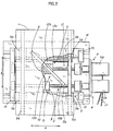
- the second actuator 7 has a threaded shaft 5b as the immovable unit 5 rotatable by a motor 5a that can rotate in the forward and reverse directions, and a nut member as the translation unit 6 for threadably meshing with the threaded shaft 5b and moving in the axial direction of the threaded shaft 5b via the rotation of the threaded shaft 5b.
- a third guide body 10a acting as third sliding means 10a is fastened to the upper surface of the translation unit 6 at a prescribed angle ⁇ 1 with respect to the translation direction of the translation unit 6.
- the third guide body 10a is disposed on the lower surface of the table 1 and is fitted onto a third guide rail 10b as third sliding means 10b disposed at a prescribed angle ⁇ 1 with respect to the translation direction of the translation unit 6.
- the prescribed angle ⁇ 1 is set at 45°.
- the third guide rail 10b is set at a 45° angle ⁇ 1 to the translation direction of the translation unit 6, as described above.
- the amount of movement of the table 1 in the second direction b increases with increased angle ⁇ 1 (as the angle approaches 90°), and the amount of movement of the table 1 in the second direction b decreases with reduced angle ⁇ 1 (as the angle approaches 0°), but a large force of movement is obtained. Therefore, the angle ⁇ 1 is not limited to 45°, but when the angle is set to 45°, an average amount and force of movement can be obtained.
- the reference numeral 17 in the diagrams indicates cords that are connected to each of the motors 2a and 5a.
- fourth sliding means 12 is disposed for guiding the translation of the translation unit 6 of the second actuator 7.
- the fourth sliding means 12 is composed of a fourth guide rail 12a that is disposed on the inner side of one of the first guide rails 8a, and a fourth guide body 12b (with a shape in which the aperture faces inward) that is disposed on the translation unit 6 of the second actuator 7 and fitted onto the fourth guide rail 12a.
- the movement of the translation unit 6 of the second actuator 7 is therefore guided by the fourth sliding means 12, the load that operates on the immovable unit 5 of the second actuator 7 is reduced when the translation unit 6 is caused to perform a translational motion and the table 1 is moved in the second direction b by using the third guide rail 10b, and the immovable unit 5 is prevented from bending.
- the first actuator 4 and second actuator 7 are disposed on the same plane, and the table can be moved in the first direction a and second direction b without the need to stack two tables. Therefore, in comparison with Patent Document 1, the configuration can be made thinner and smaller, the load placed on the singularly layered first and second actuators is reduced, the table apparatus is given better responsiveness and driving characteristics at higher speeds, the structure is simplified, and costs are reduced.
- fourth sliding means 12 is provided, and the immovable unit 5 can be prevented from bending even if the translation unit 6 of the second actuator 7 is caused to perform a translational motion, and the table 1 can be moved and controlled with greater precision.
- the present example is, therefore, a very practical table apparatus that can be made smaller and thinner.
Landscapes
- Engineering & Computer Science (AREA)
- Mechanical Engineering (AREA)
- Machine Tool Units (AREA)
- Container, Conveyance, Adherence, Positioning, Of Wafer (AREA)
Applications Claiming Priority (1)
| Application Number | Priority Date | Filing Date | Title |
|---|---|---|---|
| JP2005344238A JP4376225B2 (ja) | 2005-11-29 | 2005-11-29 | テーブル装置 |
Publications (1)
| Publication Number | Publication Date |
|---|---|
| EP1790430A1 true EP1790430A1 (de) | 2007-05-30 |
Family
ID=37776808
Family Applications (1)
| Application Number | Title | Priority Date | Filing Date |
|---|---|---|---|
| EP06019569A Withdrawn EP1790430A1 (de) | 2005-11-29 | 2006-09-19 | Tischvorrichtung |
Country Status (3)
| Country | Link |
|---|---|
| US (1) | US7823516B2 (de) |
| EP (1) | EP1790430A1 (de) |
| JP (1) | JP4376225B2 (de) |
Cited By (2)
| Publication number | Priority date | Publication date | Assignee | Title |
|---|---|---|---|---|
| DE102008063996A1 (de) * | 2008-12-19 | 2010-06-24 | Rudi Broghammer | Tisch für Objekte |
| WO2013136068A2 (en) * | 2012-03-13 | 2013-09-19 | Elopak Systems Ag | Improvements in or relating to rotary die cutting apparatus |
Families Citing this family (8)
| Publication number | Priority date | Publication date | Assignee | Title |
|---|---|---|---|---|
| WO2007066501A1 (ja) * | 2005-12-06 | 2007-06-14 | Thk Co., Ltd. | Xyテーブルアクチュエータ |
| US8104752B2 (en) * | 2006-03-20 | 2012-01-31 | Boaz Eidelberg | Integrated large XY rotary positioning table with virtual center of rotation |
| CN102554638B (zh) * | 2010-12-31 | 2016-06-29 | 富泰华工业(深圳)有限公司 | 定位机台 |
| EP3103581B1 (de) * | 2015-06-11 | 2019-10-30 | Schneeberger Holding AG | Positioniervorrichtung |
| FR3046451B1 (fr) * | 2016-01-06 | 2018-07-06 | Micro-Controle - Spectra-Physics | Systeme de generation de deplacement d'une plaque de support selon six degres de liberte. |
| CN107290119A (zh) * | 2016-04-13 | 2017-10-24 | 富泰华工业(深圳)有限公司 | 抗摔损测试机构及具有该测试机构的测试装置 |
| JP6690516B2 (ja) * | 2016-12-13 | 2020-04-28 | 株式会社デンソー | 移送装置 |
| US11938677B2 (en) * | 2020-05-14 | 2024-03-26 | John Martin Harra | Positioning system |
Citations (3)
| Publication number | Priority date | Publication date | Assignee | Title |
|---|---|---|---|---|
| EP0017144A1 (de) * | 1979-04-06 | 1980-10-15 | Hitachi, Ltd. | Vorrichtung zum genauen Versetzen eines Tisches |
| GB2188263A (en) * | 1986-02-28 | 1987-09-30 | Nippon Seiko Kk | Composite movement table apparatus |
| US4896869A (en) * | 1987-10-30 | 1990-01-30 | Tokyo Electron Limited | Moving table apparatus |
Family Cites Families (16)
| Publication number | Priority date | Publication date | Assignee | Title |
|---|---|---|---|---|
| US3495519A (en) * | 1967-02-01 | 1970-02-17 | Microform Data Systems | Xy table |
| JPS61230829A (ja) | 1985-04-04 | 1986-10-15 | Toshiba Mach Co Ltd | ステ−ジ装置 |
| JP2557316Y2 (ja) * | 1990-02-28 | 1997-12-10 | エヌティエヌ 株式会社 | 移動テーブル |
| DE4107881C2 (de) * | 1990-03-13 | 1997-04-17 | Ntn Toyo Bearing Co Ltd | Verstellbarer Tisch |
| JPH05277870A (ja) * | 1992-03-27 | 1993-10-26 | Nippon Thompson Co Ltd | 駆動装置及びこれを具備したxy駆動装置 |
| JPH05280610A (ja) * | 1992-03-31 | 1993-10-26 | Nippon Seiko Kk | 位置決めテーブル装置 |
| JPH0818210B2 (ja) * | 1992-05-15 | 1996-02-28 | 健 柳沢 | 2次元運動機構 |
| JP3346838B2 (ja) * | 1993-06-29 | 2002-11-18 | 有限会社創造庵 | 回転運動機構 |
| JP3459315B2 (ja) * | 1994-07-11 | 2003-10-20 | 日本トムソン株式会社 | ボールねじを具備した駆動装置及び該駆動装置を含むxy駆動装置 |
| JP3966921B2 (ja) | 1996-07-19 | 2007-08-29 | 日本ベアリング株式会社 | テーブル装置 |
| JP3878252B2 (ja) * | 1996-07-19 | 2007-02-07 | 日本ベアリング株式会社 | テーブル装置 |
| US5724893A (en) * | 1996-10-15 | 1998-03-10 | Taichung Machinery Works Co. Ltd. | Servo-type shaking table assembly |
| JPH11300557A (ja) * | 1998-04-15 | 1999-11-02 | Thk Co Ltd | 移動テーブル装置 |
| DE69820426T2 (de) * | 1998-07-14 | 2004-10-07 | Kummer Freres Sa | Antriebseinrichtung für die Bewegung einer Plattform in einer Ebene |
| JP2000230991A (ja) * | 1999-02-12 | 2000-08-22 | Takeshi Yanagisawa | 2次元運動機構 |
| JP4485138B2 (ja) * | 2003-03-31 | 2010-06-16 | 日本トムソン株式会社 | 2軸直動・旋回案内ユニット及びそれを用いたテーブル装置 |
-
2005
- 2005-11-29 JP JP2005344238A patent/JP4376225B2/ja not_active Expired - Fee Related
-
2006
- 2006-09-14 US US11/531,763 patent/US7823516B2/en not_active Expired - Fee Related
- 2006-09-19 EP EP06019569A patent/EP1790430A1/de not_active Withdrawn
Patent Citations (3)
| Publication number | Priority date | Publication date | Assignee | Title |
|---|---|---|---|---|
| EP0017144A1 (de) * | 1979-04-06 | 1980-10-15 | Hitachi, Ltd. | Vorrichtung zum genauen Versetzen eines Tisches |
| GB2188263A (en) * | 1986-02-28 | 1987-09-30 | Nippon Seiko Kk | Composite movement table apparatus |
| US4896869A (en) * | 1987-10-30 | 1990-01-30 | Tokyo Electron Limited | Moving table apparatus |
Cited By (3)
| Publication number | Priority date | Publication date | Assignee | Title |
|---|---|---|---|---|
| DE102008063996A1 (de) * | 2008-12-19 | 2010-06-24 | Rudi Broghammer | Tisch für Objekte |
| WO2013136068A2 (en) * | 2012-03-13 | 2013-09-19 | Elopak Systems Ag | Improvements in or relating to rotary die cutting apparatus |
| WO2013136068A3 (en) * | 2012-03-13 | 2014-01-09 | Elopak Systems Ag | Improvements to rotary die cutting apparatus |
Also Published As
| Publication number | Publication date |
|---|---|
| US7823516B2 (en) | 2010-11-02 |
| JP4376225B2 (ja) | 2009-12-02 |
| US20070119347A1 (en) | 2007-05-31 |
| JP2007144584A (ja) | 2007-06-14 |
Similar Documents
| Publication | Publication Date | Title |
|---|---|---|
| US7823516B2 (en) | Table apparatus | |
| US7901167B2 (en) | Machining apparatus with mechanism for retaining axial position of guide member | |
| WO2016082741A1 (zh) | 直线电机共定子双驱动宏微一体化高速精密运动一维平台 | |
| EP3267072A3 (de) | Stellglied zur bereitstellung einer relativbewegung zwischen zwei punkten | |
| JP2798829B2 (ja) | 2次元運動機構 | |
| KR20160042876A (ko) | 피가공물용 이송 장치 | |
| CN101157183A (zh) | 两自由度车削刀具精密伺服驱动装置 | |
| US12036658B2 (en) | Device for supporting a load | |
| EP3603881A1 (de) | Bearbeitungszentrum | |
| US7607234B2 (en) | Positive load alignment mechanism | |
| CN211594198U (zh) | 用于高速转向移动搬运的龙门双驱四轴结构 | |
| CN219925305U (zh) | 一种用于轴类零件平面铣削的夹紧装置 | |
| US11529667B2 (en) | Plate material, feeding device | |
| KR20120017281A (ko) | 얼라인 스테이지 시스템 | |
| WO2019172855A1 (en) | A section handling machine | |
| KR20030006756A (ko) | 일렬로 배치되어 직선운동하는 두 이동부재를 이용한작업대 이동장치 | |
| EP2069104B1 (de) | Ruckentkoppelte antriebsachse | |
| CN103878624B (zh) | 双轴并联进给平台机构 | |
| JP5141191B2 (ja) | 縦型位置決めテーブル | |
| JP7180895B2 (ja) | 位置決めテーブル | |
| JP2014084975A (ja) | 直動テーブル装置及び直動テーブル装置のボールねじサポート機構 | |
| CN220178766U (zh) | 角度可调的动力头 | |
| EP2687324A2 (de) | Zuführvorrichtung und Maschinenwerkzeug damit | |
| US11331712B2 (en) | Transfer mechanism and transfer device | |
| CN212286321U (zh) | 一种激光切割头运动组件 |
Legal Events
| Date | Code | Title | Description |
|---|---|---|---|
| PUAI | Public reference made under article 153(3) epc to a published international application that has entered the european phase |
Free format text: ORIGINAL CODE: 0009012 |
|
| AK | Designated contracting states |
Kind code of ref document: A1 Designated state(s): AT BE BG CH CY CZ DE DK EE ES FI FR GB GR HU IE IS IT LI LT LU LV MC NL PL PT RO SE SI SK TR |
|
| AX | Request for extension of the european patent |
Extension state: AL BA HR MK YU |
|
| STAA | Information on the status of an ep patent application or granted ep patent |
Free format text: STATUS: THE APPLICATION HAS BEEN WITHDRAWN |
|
| 18W | Application withdrawn |
Effective date: 20070927 |