EP1789243B1 - Dry-forming three-dimensional wood fiber webs - Google Patents
Dry-forming three-dimensional wood fiber webs Download PDFInfo
- Publication number
- EP1789243B1 EP1789243B1 EP05759205.7A EP05759205A EP1789243B1 EP 1789243 B1 EP1789243 B1 EP 1789243B1 EP 05759205 A EP05759205 A EP 05759205A EP 1789243 B1 EP1789243 B1 EP 1789243B1
- Authority
- EP
- European Patent Office
- Prior art keywords
- dimensional
- dry
- web
- mat
- wood
- Prior art date
- Legal status (The legal status is an assumption and is not a legal conclusion. Google has not performed a legal analysis and makes no representation as to the accuracy of the status listed.)
- Expired - Lifetime
Links
Images


Classifications
-
- B—PERFORMING OPERATIONS; TRANSPORTING
- B32—LAYERED PRODUCTS
- B32B—LAYERED PRODUCTS, i.e. PRODUCTS BUILT-UP OF STRATA OF FLAT OR NON-FLAT, e.g. CELLULAR OR HONEYCOMB, FORM
- B32B21/00—Layered products comprising a layer of wood, e.g. wood board, veneer, wood particle board
- B32B21/02—Layered products comprising a layer of wood, e.g. wood board, veneer, wood particle board the layer being formed of fibres, chips, or particles, e.g. MDF, HDF, OSB, chipboard, particle board, hardboard
-
- B—PERFORMING OPERATIONS; TRANSPORTING
- B27—WORKING OR PRESERVING WOOD OR SIMILAR MATERIAL; NAILING OR STAPLING MACHINES IN GENERAL
- B27N—MANUFACTURE BY DRY PROCESSES OF ARTICLES, WITH OR WITHOUT ORGANIC BINDING AGENTS, MADE FROM PARTICLES OR FIBRES CONSISTING OF WOOD OR OTHER LIGNOCELLULOSIC OR LIKE ORGANIC MATERIAL
- B27N3/00—Manufacture of substantially flat articles, e.g. boards, from particles or fibres
- B27N3/08—Moulding or pressing
-
- B—PERFORMING OPERATIONS; TRANSPORTING
- B27—WORKING OR PRESERVING WOOD OR SIMILAR MATERIAL; NAILING OR STAPLING MACHINES IN GENERAL
- B27N—MANUFACTURE BY DRY PROCESSES OF ARTICLES, WITH OR WITHOUT ORGANIC BINDING AGENTS, MADE FROM PARTICLES OR FIBRES CONSISTING OF WOOD OR OTHER LIGNOCELLULOSIC OR LIKE ORGANIC MATERIAL
- B27N5/00—Manufacture of non-flat articles
-
- B—PERFORMING OPERATIONS; TRANSPORTING
- B29—WORKING OF PLASTICS; WORKING OF SUBSTANCES IN A PLASTIC STATE IN GENERAL
- B29C—SHAPING OR JOINING OF PLASTICS; SHAPING OF MATERIAL IN A PLASTIC STATE, NOT OTHERWISE PROVIDED FOR; AFTER-TREATMENT OF THE SHAPED PRODUCTS, e.g. REPAIRING
- B29C43/00—Compression moulding, i.e. applying external pressure to flow the moulding material; Apparatus therefor
- B29C43/003—Compression moulding, i.e. applying external pressure to flow the moulding material; Apparatus therefor characterised by the choice of material
-
- B—PERFORMING OPERATIONS; TRANSPORTING
- B29—WORKING OF PLASTICS; WORKING OF SUBSTANCES IN A PLASTIC STATE IN GENERAL
- B29C—SHAPING OR JOINING OF PLASTICS; SHAPING OF MATERIAL IN A PLASTIC STATE, NOT OTHERWISE PROVIDED FOR; AFTER-TREATMENT OF THE SHAPED PRODUCTS, e.g. REPAIRING
- B29C51/00—Shaping by thermoforming, i.e. shaping sheets or sheet like preforms after heating, e.g. shaping sheets in matched moulds or by deep-drawing; Apparatus therefor
- B29C51/08—Deep drawing or matched-mould forming, i.e. using mechanical means only
- B29C51/082—Deep drawing or matched-mould forming, i.e. using mechanical means only by shaping between complementary mould parts
-
- B—PERFORMING OPERATIONS; TRANSPORTING
- B32—LAYERED PRODUCTS
- B32B—LAYERED PRODUCTS, i.e. PRODUCTS BUILT-UP OF STRATA OF FLAT OR NON-FLAT, e.g. CELLULAR OR HONEYCOMB, FORM
- B32B21/00—Layered products comprising a layer of wood, e.g. wood board, veneer, wood particle board
-
- B—PERFORMING OPERATIONS; TRANSPORTING
- B32—LAYERED PRODUCTS
- B32B—LAYERED PRODUCTS, i.e. PRODUCTS BUILT-UP OF STRATA OF FLAT OR NON-FLAT, e.g. CELLULAR OR HONEYCOMB, FORM
- B32B3/00—Layered products comprising a layer with external or internal discontinuities or unevennesses, or a layer of non-planar shape; Layered products comprising a layer having particular features of form
- B32B3/26—Layered products comprising a layer with external or internal discontinuities or unevennesses, or a layer of non-planar shape; Layered products comprising a layer having particular features of form characterised by a particular shape of the outline of the cross-section of a continuous layer; characterised by a layer with cavities or internal voids ; characterised by an apertured layer
- B32B3/28—Layered products comprising a layer with external or internal discontinuities or unevennesses, or a layer of non-planar shape; Layered products comprising a layer having particular features of form characterised by a particular shape of the outline of the cross-section of a continuous layer; characterised by a layer with cavities or internal voids ; characterised by an apertured layer characterised by a layer comprising a deformed thin sheet, i.e. the layer having its entire thickness deformed out of the plane, e.g. corrugated, crumpled
-
- B—PERFORMING OPERATIONS; TRANSPORTING
- B29—WORKING OF PLASTICS; WORKING OF SUBSTANCES IN A PLASTIC STATE IN GENERAL
- B29C—SHAPING OR JOINING OF PLASTICS; SHAPING OF MATERIAL IN A PLASTIC STATE, NOT OTHERWISE PROVIDED FOR; AFTER-TREATMENT OF THE SHAPED PRODUCTS, e.g. REPAIRING
- B29C59/00—Surface shaping of articles, e.g. embossing; Apparatus therefor
- B29C59/02—Surface shaping of articles, e.g. embossing; Apparatus therefor by mechanical means, e.g. pressing
-
- B—PERFORMING OPERATIONS; TRANSPORTING
- B29—WORKING OF PLASTICS; WORKING OF SUBSTANCES IN A PLASTIC STATE IN GENERAL
- B29K—INDEXING SCHEME ASSOCIATED WITH SUBCLASSES B29B, B29C OR B29D, RELATING TO MOULDING MATERIALS OR TO MATERIALS FOR MOULDS, REINFORCEMENTS, FILLERS OR PREFORMED PARTS, e.g. INSERTS
- B29K2105/00—Condition, form or state of moulded material or of the material to be shaped
- B29K2105/26—Scrap or recycled material
Definitions
- a wide variety of forest products are manufactured from wood fibers.
- Nearest prior art document U.S. 5,900,304 focuses upon a class of wood-fiber products that are molded in three dimensions under conditions of heat and pressure to produce a structural wood fiber web that serves as the principal structural component of composite structural-fiberboard panels.
- the geometry of the web permits the use of a simple rigid mold that may be pressed together with one-dimensional forces.
- the composite structure forms a strong, lightweight, rigid three-dimensional truss.
- U.S. 4,702,870 (“US '870”) describes a method and apparatus for forming three-dimensional structural components from wood fiber.
- This method and apparatus require the use of a resilient mold insert to form three-dimensional features in the finished fiberboard product.
- the resilient mold insert is most commonly composed of an array of elastomeric protuberances.
- the elastomers are attached to a rigid support plate.
- elastomeric mold elements can exhibit problems with compression-set and relatively rapid deterioration under the heat and pressure necessary for product consolidation and drying.
- the elastomeric mold elements have a relatively short lifetime and need to be frequently replaced in high-speed production facilities.
- the three-dimensional fiberboard objects disclosed are limited to objects having a flat face, backed by webs extending approximately normal to the flat face, backed by webs of identical fiber composition.
- Heat transfer from the resilient mold insert of US '870 to the fiber mat is slow because of the low thermal conductivity of the elastomeric elements of the mold inert and because of long thermal-conduction pathways to regions of the fiber between the elastomeric mold elements. Slow heat transfer results in long drying times within the press, a major problem for this method, particularly for thick products. Drying speed may be increased using radiowave heating of the fiber mat, but this increases the complexity and cost of equipment used to form and dry the fiberboard products.
- a process for making grids from fibers also uses the idea of a resilient mold insert which is capable of forming objects in three-dimensions. Because of the use of a resilient mold insert, this invention suffers from the same difficulties as does US '870. In addition, while this mold insert is capable of generating three-dimensional forces, it is used to generate a fiber product that has generally two-dimensional features only.
- U.S. 5,198,236 and 5,314,654 describe a method and apparatus that uses a rigid mold to form three-dimensional features in structural fiberboard products. These fiberboard products are limited to flat-faced objects backed by webs extending approximately normal to the flat face. In addition, the rigid mold elements disclosed must be retracted during consolidation of the fiber. In U.S. 5,314,654 , a second forming step is required using a resilient mold insert similar to that of US '870. Therefore, formation of this structural fiberboard product suffers from the same difficulties as have been pointed out for US '870. In addition, the need for retractable mold elements makes this method complex and expensive.
- U.S. 5,316,828 (“US '828”); reveals a reinforced fluted medium and corrugated fiberboard that has increased strength and stiffness in comparison to conventional corrugated fiberboard due to the addition of three-dimensional elements in a simple corrugated fiberboard structure.
- the three-dimensional elements take the form of adhesive material applied along lines that are transverse to the flutes. The adhesive at least partially fills in and bridges across the valleys of the flutes, holding the corrugated board more rigid under compressive and bending stresses both along the corrugations and across the corrugations.
- US '828 The structure of US '828 is therefore not formed as a single piece and requires multiple manufacturing steps.
- considerable adhesive is required to fill in the valleys to the top of the flutes.
- the adhesive could fill in and bridge only a small portion of the flutes in thick corrugated boards, making the technique ineffective for thick corrugated panels.
- application of adhesive to both sides of the fluted medium would increase product weight and material cost, and complicate board manufacture.
- U.S. 4,726,863 describes a method for making a high-strength composite paperboard panel.
- the panel is composed of an undulated midstratum layer to which are adhesively bonded an underlayer and an overlayer. There is no variation of the structure along the flutes formed by the undulations, making the structure generally two-dimensional and placing it in a different structural class than the present invention. Because of its two-dimensional structure, which is similar to the structure of conventional corrugated boards, this panel product has less strength and stiffness across the undulations compared to along the undulations.
- U.S. Patent 5,900,304 describes a wet-formed three-dimensional core for structural composites.
- the three-dimensional wood-fiber web can be produced using a simple rigid mold pressed together with one-dimensional pressing forces.
- the fiber webs are made using a wet-forming process in which the wood fiber is prepared by mixing the fiber with water, thereby forming a slurry.
- the fiber web is formed as one piece under heat and pressure after most of the carrier fluid is drained or squeezed from the slurry as the rigid mold is pressed together.
- the fiber web contains corrugations that have syncline (V-shaped) indentations along the ridges of the corrugations on both sides of the web at spaced positions along the ridges of the corrugations.
- the opposite surface of the indentations form anticline (inverted V shaped) protrusions that function as corrugation stiffeners bridging across furrows of the corrugations.
- These elements produce sloped web surfaces.
- the valleys and ridges of these elements may be flat.
- Flat ridges provide an exterior surface for the application of adhesives that bond the web to additional components. Surfaces that are either sloping or flat allow formation of the web using a simple rigid mold that is pressed together using a one-dimensional pressing force.
- sheets of material are adhesively bonded to the flat ridges of the shaped web on one or both sides of the web, providing smooth facings which cover the web.
- the web thereby serves as a stiff, lightweight structural core which is sandwiched between sheet facings to form a composite panel.
- the combined structure consists of a three-dimensional web bonded to sheet material.
- U.S. Patent 6,451,235 describes a wet process for forming a three-dimensional core from an aqueous slurry of fibers employing press drying to produce a strong core structure.
- Wet-formation techniques can be employed for producing deeply drawn three-dimensional structural cores using what is said to be the natural plasticity and conformability of wet fibers.
- the use of wet fibers can enable the forming, drawing and bonding of such structures without the use of complicated mold designs and complex formation processes.
- a commercial product, SONOBoard TM based on technology described in U.S. Patent 4,702,870 , can utilize a complex deformable mold upon which an aqueous slurry of fibers can be formed into a three-dimensional honeycomb with one flat face.
- the wet pre-form composition can be wet-pressed and then transferred to a hot press wherein it can be press-dried to form a semi-rigid composite structure. Two of these structures can be laminated along the honeycomb face to produce a flat, rigid panel.
- Another form of this product is commercially known as Gridcore TM .
- Drying of a wet-formed three-dimensional core has been determined to be too time consuming to complete and an inefficient method of formation. It requires an excessive amount of expensive thermal energy to implement the drying process of the wet formed material. Wet forming also requires that large volumes of water be recycled. The aqueous effluent contains fine fiber fragments and dissolved solids which are ultimately purged in waste water streams that require pollution abatement treatment.
- U.S. 5,900,304 are produced using a wet-formation mold.
- a description of an exemplary mold for conducting the wet-formation process is provided in U.S. 5,900,304 , at col. 5, lines 1-52 and col. 5, line 65 through col. 6, line 6.
- the subject dry-formation method can form three dimensional structural cores of high quality as compared to those produced by wet formation techniques. Furthermore, modifications in the design of the molds of U. S. Patent 5,900,304 can be provided that improve their performance in dry-formed production of deeper cores while maintaining structural integrity, high strength and excellent laminating properties without telegraphing core patterns through the panel facings.
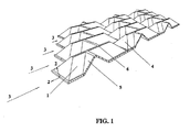
- FIG. 1 shows an upper surface view of the pressed-fiber web consisting of a series of undulations or corrugations 1 along which are numerous V-shaped openings (referred to hereinafter as syncline indentations 4) downward into the ridges of the corrugations and other numerous inverted-V-shaped protuberances (referred to hereinafter as anticline protrusions 5) upward from the valleys of the corrugations.
- the anticline protrusions 5 may have the same height as the corrugations, as shown in FIG. 1 , or they may be set back from the ridges of the corrugations.
- the midplane of the web may be defined as a horizontal plane which passes through the middle of the structure in the narrow overall height dimension.
- the midplane is generally normal to the direction in which force is applied to form the web.
- the direction of the valleys of the syncline indentations 4 and the ridges of the anticline protrusions 5 are approximately normal to the axes of the corrugations. Other relative angles may be used if desired.
- the anticline protrusions 5 are formed by indenting the valleys of the corrugations from the underside of the structure shown in FIG. 1 . Both the syncline indentations 4 and the anticline protrusions 5 are indentations into corrugation ridges made in the same fashion but from opposite sides of the fiber web structure.
- the walls formed by the syncline indentations 4 and anticline protrusions 5 span or bridge the space between adjacent walls of the corrugations. By bridging this space, the syncline indentations 4 and anticline protrusions 5 can act as a gusset or stiffener for the corrugations 1. They can also provide strength and stiffness in directions normal to the axes of the corrugations.
- the fiber web can hold its as-molded form without the need for additional support.
- the self-supporting feature of the fiber web makes assembly into stacked configurations very simple and convenient. The self-supporting feature also allows the web to be used in the as-molded condition, which can be useful in some packaging applications.
- the peaks or ridges 6 of the structure on both the top and bottom surfaces of the web may be flat. These flat features along the ridges form surfaces that are convenient and can be effective sites for the application of adhesives used to bond the structure to various types of sheet coverings or facings, or to bond several webs together to form stacked configurations. As depicted in FIG. 1 , these flat-topped ridges may comprise peaks or ridges of the anticline protrusions 5 in addition to peaks or ridges of the corrugations 1.
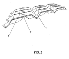
- FIG. 2 provides a further perspective drawing of the first embodiment.
- the structure shown in FIG. 1 has been sectioned along plane 2--2 of FIG. 1 to reveal some of the features of the cross-section and the underside of the structure.
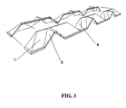
- FIG. 3 is another perspective drawing showing a single corrugation that has been split apart at a plane through the middle of the corrugation. The formation of the anticline protrusions 5 by indentation of the valleys of the corrugations is clarified in FIGS. 2 and 3 .
- the structure is a relatively thin three-dimensional web having sloping surfaces and flat ridges.
- the topology of the structure of the present invention permits formation of the three-dimensional web as a single continuous piece in a single molding operation using a simple rigid mold that is pressed together with one-dimensional forming forces.
- the top and bottom mold surfaces used to form the present invention contain negative impressions of the top and bottom surfaces, respectively, of the structure. Unidirectional mold pressure is applied in a direction generally normal to the planar axis or midplane of the web structure.
- the ability to form the fiber web as a single piece in a single molding step using a rigid mold is characterized in that the web surfaces comprise single-valued functions of coordinates of the midplane of the structure. No part of the web is therefore intersected more than once as the mold moves towards the web in its finished form. No part of the web folds back on itself or has hollow regions, which would otherwise make rigid mold access impossible in a single molding step to form a single continuous web.
- the angled or sloped surfaces of the web permit ready formation of the three-dimensional web structure, they also permit ready separation of the mold from the web after formation of the web. Excellent mold-release properties are provided.
- FIG. 4A shows a top view of a three-dimensional fiber web that is similar to the web depicted in FIGS. 1 and 2 . In this case, a little larger web is shown having more indentations and protrusions.
- the top view shows a skewed shape intentionally, in order to clarify the web structure or pattern.
- the web can be made to have a rectangular perimeter or any other perimeter shape by trimming the edges or forming the web with the desired perimeter shape.
- the flat-topped ridges 7 of the structure are represented by the heavy black lines in the top view, while the flat-bottomed valleys 8 are represented by the hatched pattern in the top view.
- the flat portion of the ridges 7 forms an excellent surface for applying adhesive used to bond the web to facings or other fiber webs.
- the thin angled lines in the top view are the edges of syncline indentations into the paper and anticline protrusions out of the paper.
- the diamond shaped elements in FIG. 4 containing hatched horizontal lines represent syncline indentations 9, while those containing heavy solid lines represent anticline protrusions 10.
- FIG. 4B shows a lower-edge view of the structure depicted in FIG. 4A .
- the view presented in FIG. 4B is indicated by cross section 4B-4B in FIG. 4A .
- An end view of the corrugations 11 and the sides of the anticline protrusions 10 are visible in this view.
- FIG. 4C shows a right edge view of the web showing yet another view of the syncline indentations 9 and anticline protrusions 10.
- the right edge view in FIG. 4C is indicated by cross section 4C-4C in FIG. 4A .
- the positions of the syncline indentations 9 and the anticline protrusions 10 are staggered along adjacent corrugations. By staggering these elements, bending strength and stiffness may be imparted to the structure both along the corrugations and across the corrugations.
- FIG. 5A is a top view of a web in which syncline indentations 12 and anticline protrusions 13 are lined up in a direction normal to the corrugations to facilitate bending or folding of the web across the corrugations.
- a lower edge view of this embodiment is shown in FIG. 5B and a right edge view is shown in FIG. 5C .
- the topology of this particular embodiment permits the use of molds that can be readily machined on three-axis milling machines from a single piece of rigid material. Somewhat greater distances are shown between the indentations and protrusions in FIG. 5 , compared to FIG. 4 , to illustrate the fact that the spacing and position of the syncline indentations 12 and anticline protrusions 13 can be varied. The appropriate positions and spacing will be determined by product application requirements such as strength across the corrugations, economics of mold fabrication, final product shape, and end use.
- the ability to fold or bend the web is an advantage in numerous applications.
- the web in the manufacture of boxes, the web may be folded at the corners and subsequently covered with a facing to produce a smooth surface. Box assembly in this sequence is greatly facilitated by the fact that the webs are self-supporting in the as-molded condition.
- Either stiff sheet materials, such as wood, metal and hard plastics, or more flexible sheet materials, such as thin fiberboard or paperboard, may be applied to the web to form the box surface in this case.
- folding may be performed after the facing is applied to the web, as is done in conventional corrugated board manufacture. In this case, the facing must be flexible in order to allow the facing to be creased along the fold line prior to bending.
- FIG. 6 illustrates smooth, flat-surface sheets 17 that may be bonded to the ridges 18 of the fiber web 19.
- a web 19 like that illustrated in FIG. 5 can be drawn.
- the composite structure becomes a flat surface panel with a fiber web 19 backing or core.
- the sheet material 17 applied to the web 19 spans the gap across the tops of the syncline indentations 12 forming a rigid three-dimensional truss.
- the three-dimensional truss formed in this way imparts considerable stiffness to the composite panel.
- the smooth surface sheets 17 applied to the web provide excellent surfaces for printing and displaying text and graphics, useful for conveying information and advertising. Printing may be performed either before or after the sheets are joined to the web. While shown as a generally flat panel in FIG. 5 , curved shapes are also readily produced by forming or bending the web 19 in an arc and bonding flexible sheets to the web 19 so that the sheets follow the curvature of the fiber web 19.
- the facings may consist of wood veneers, sheets of wood-fiber-based material, wood-based-particle panel materials, plastic or metal sheets.
- FIG. 7A is a top view of an embodiment in which several individual fiber webs 19 are bonded together in a stacked configuration.
- FIG. 7B is a bottom edge view of the stack of webs and
- FIG. 7C is a right edge view of the stacked web.
- the webs 19 may be readily bonded along the surfaces formed at the ridges 14 of the individual webs 19.
- the gaps at the top of the syncline indentations 12 are bridged by stiff portions of the ridges 14 of adjacent webs 19.
- the structure becomes a complex rigid three-dimensional truss having considerable stiffness in all directions. Stiffness is attained in this case without the use of sheet facings.
- stacked-webs generally have better thermal insulating properties than do panels consisting of only a single large web. This advantage is due primarily to the separation or partitioning of air spaces through the thickness of the stacked web. By partitioning the air spaces, circulating air currents are broken up and isolated from each other. Heat transfer through the thickness of the stacked web due to heat convection along these air currents is thereby minimized.
- sheets of material may also be applied between webs 19 within the stack of webs. This additional layering of sheet material imparts additional strength and stiffness to the composite panel and increased convective heat-transfer resistance across the panel. Increased convective heat-transfer resistance results from further separation and partitioning of the air spaces within the stacked web in these embodiments.
- FIG. 8 depicts the application of sheet facings 17 to the ridges 14 of exterior webs of the stacked configuration, to give the stack greater stiffness and a smooth surface. Sheets may or may not be placed between webs 19 within the stack, depending upon the application.
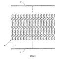
- FIG. 9 shows an embodiment in which numerous webs 19 are stacked horizontally.
- sheet facings are applied to the edges of the stack rather than to the exterior web ridges 14.
- individual webs would typically have a narrow width (height dimension in FIG. 9 ) relative to web overall length (dimension into the paper in FIG. 9 ).
- the stacked web and sheet facings depicted in FIG. 9 would be useful in the formation of relatively thick beams and platforms in which heavy loads are applied to the edges of the webs 19.
- sheet coverings along the edge of stacked panels would keep debris from entering the stack of webs.
- sheet materials may be placed between webs within the stack shown in FIG. 9 to impart additional strength and stiffness to the composite structure.
- sheet facings may also be readily applied to the edges of the composite panel at the right, left and facing views of the structure depicted in FIG. 9 . With the addition of these sheet facings, the composite panel would be completely enclosed on all sides by smooth facings.
- the invention in its various forms can be used to make a wide variety of structural products in packaging, material handling, construction and furniture industries.
- Products include pallets, bulk bins, heavy duty boxes, shipping containers, wall panels, roof panels, cement forms, partitions, poster displays, reels, desks, caskets, shelves, tables, and doors.
- the invention can be formed from wood fibers of all types with resin or binder additives to enhance properties.
- the invention can also include various other additives and treatments to impart specific properties to the structure such as resistance to water, fire, and insects.
- the wood fibers can be blended with recycled or virgin plastic materials and other components selected to impart specific properties to the final product including, but not limited to, polyethylene, polyvinyl chloride, fire retardant compounds, clays, wet strength additives, waxes, and/or biocides.
- polyethylene polyvinyl chloride
- fire retardant compounds such as, but not limited to, polyethylene, polyvinyl chloride, fire retardant compounds, clays, wet strength additives, waxes, and/or biocides.
- urea formaldehyde or phenol formaldehyde resins, methylene diisocyanate resin or related binders can be added to the wood fibers.
- Adhesive is typically blended with the above wood fibers to achieve thorough mixing and dispensing of the adhesives. These adhesives are employed to bond the wood fibers into a preformed, substantially flat, dry-formed mat of wood fibers and ultimately into into a three-dimensional wood fiber structural core.
- the adhesive bonding system of the present invention generally comprises an isocyanate polymer and/or an aldehyde polymer resin.
- the adhesive bonding system can also be an isocyanate/latex copolymer or a phenol-formaldehyde/latex copolymer.
- Another adhesive bonding system which can be employed herein is a soy-based adhesive system which comprises an aldehyde-free wet strength additive that can be applied to wood fibers in a single admixture addition or sequentially in a two-component adhesive application.
- the polymers, which form the adhesive bonding system are typically in liquid form so that they can be applied directly to a major surface of a layer of lignocellulosic material. The polymer resins can be combined together prior to their application.
- the aldehyde polymer resins can comprise thermosetting resins such as phenol-formaldehyde, resorcinol-formaldehyde, melamine-formaldehyde, ureaformaldehyde, modified lignosulfonates, urea-furfural and condensed furfuryl alcohol resins.
- the phenolic component can include any one or more of the phenols which have heretofore been employed in the formation of phenolic resins and which are not substituted at either the two ortho-positions or at one ortho- and the para-position, such unsubstituted positions being necessary for the polymerization reaction. Any one, all, or none of the remaining carbon atoms of the phenol ring can be substituted.
- Substituted phenols employed in the formation of the phenolic resins include: alkyl-substituted phenols, aryl-substituted phenols, cyclo-alkyl-substituted phenols, alkenyl-substituted phenols, alkoxy-substituted phenols, aryloxy-substituted phenols, and halogen-substituted phenols, the foregoing substituents containing from 1 to 26 and preferably from 1 to 12 carbon atoms.
- Suitable phenols include: phenol, 2,6 xylenol, o-cresol, m-cresol, p-cresol, 3,5-xylenol, 3-4-xylenol, 2,3,4-trimethyl phenol, 3-ethyl phenol, 3,5-diethyl phenol, p-butyl phenol, 3,5-dibutyl phenol, p-amyl phenol, p-cyclohexyl phenol, p-octyl phenol, 3,5-dicyclohexyl phenol, p-phenyl phenol, p-crotyl phenol, 3,5-dimethoxy phenol, 3,4,5-trimethoxy phenol, p-ethoxy phenol, p-butoxy phenol, 3-methyl-4-methoxy phenol, and p-phenoxy phenol.
- the aldehydes reacted with the phenol can include any of the aldehydes heretofore employed in the formation of phenolic resins such as formaldehyde, acetaldehyde, propionaldehyde, furfuraldehyde, and benzaldehyde.
- the aldehydes employed have the formula R'CHO wherein R' is a hydrogen or a hydrocarbon radical of 1 to 8 carbon atoms. The most preferred aldehyde is formaldehyde.
- the isocyanate polymer may suitably be any organic isocyanate polymer compound containing at least 2 active isocyanate groups per molecule, or mixtures of such compounds.
- the isocyanate polymers employed in the method of this invention are those which have an isocyanato group functionality of at least about two. Preferably, this functionality ranges from 2.3 to 3.5 with an isocyanate equivalent of 132 to 135.
- the isocyanato functionality can be determined from the percent available NCO groups and the average molecular weight of the isocyanate polymer composition. The percent available NCO groups can be determined by the procedures of ASTM test method D1638.
- the isocyanate polymers which can be employed in the method of the present invention can be those that are typically employed in adhesive compositions, including typical aromatic, aliphatic and cycloaliphatic isocyanate polymers.
- Representative aromatic isocyanate polymers include 2,4-tolylene diisocyanate, 2,6-tolylene diisocyanate, 4,4'-methylene bis(phenyl isocyanate), 1,3-phenylene diisocyanate, triphenylmethane triisocyanate, 2,4,4'-triisocyanatodiphenyl ether, 2,4-bis(4-isocyanatobenzyl) phenylisocyanate and related polyaryl polyiscocyanates, 1,5-naphthalene diisocyanate and mixtures thereof.
- Representative aliphatic isocyanate polymers include hexamethylene diisocyanate, xylylene diisocyanate, and 1,12-dodecane diisocyanate and lysine ethyl ester diisocyanate.
- Representative cycloaliphatic isocyanate polymers include 4,4'-methylenebis (cyclohexyl isocyanate), 1,4-cyclohexylene diisocyanate, 1-methyl-2, 4-cyclohexylene diisocyanate and 2,4-bis(4-isocyanatocyclhexylmethyl) cyclohexyl isocyanate.
- the isocyanate polymer is typically applied in its liquid form.
- a phenol-formaldehyde resin is used as the phenolic resin it is present in the adhesive composition used in the method of the present invention within the range of about 50 to 90% by weight, preferably within the range of about 60 to 80% by weight of the total amount of adhesive.
- the isocyanate polymer is present in an amount of preferably from about 3 weight %, more preferably from about 5 weight %, most preferably from about 7 weight %, up to about 30 weight %, more preferably up to about 25 weight %, and most preferably up to about 20 weight %, based on the total weight of the mat of wood fibers.
- the forming of a pre-formed, substantially flat, dry mat of treated wood fibers can be accomplished by feeding the treated dry wood fibers, or blends thereof, through the air by gravity at controlled rates. These gravity-fed, treated dry wood fibers or blends are uniformly distributed over a planar forming area or vacuum forming bed to form a mat having a pre-detennined basis weight (weight per unit area). This mat is then pre-compressed to increase its mechanical cohesiveness sufficiently for subsequent handling and loading into a discontinuous or continuous hot press outfitted with the three-dimensional molds of type outlined in U.S. Patent 5,900,304 .
- the pre-formed, pre-compressed, flat dry mat is then pressed between the three-dimensional molds for a pre-determined period of time using pressing protocols that are sufficient to allow the preformed, pre-compressed, dry mat to be drawn and molded into a three-dimensional structure in a single pressing motion.
- Preferred single pressing motions for forming the subject cores can be effected within an intermittent or continuous mold configuration.
- thermosetting binder, waxes and other additives are cured as the mat is drawn within the three-dimensional contours of the molds. Furthermore, any moisture present is thermally evaporated in a manner that provides for release of escaping water vapor without disrupting the consolidated, thermo-bonded core as pressure is relieved at the end of the pressing cycle.
- Moisture content of the mats introduced into the molds is preferably from about 5 weight %, more preferably from about 6 weight %, most preferably from about 8 weight %, up to about 20 weight %, more preferably up to about 16 weight %, and most preferably up to about 12 weight %, based on the total weight of the oven dry wood solids.
- wet-formed mats after pre-compressing and prior to introduction into a hot pressing stage for dewatering, drying and consolidation are in a moisture content in a typical range of at least about five times, in another embodiment at least about seven times, in a further embodiment at least about eight times, and in an even further embodiment at least about ten times higher than the dry mats.
- the duration of the pressing cycle is preferably from about 30 seconds, more preferably from about 35 seconds, most preferably from about 40 seconds, preferably up to about 120 seconds, more preferably up to about 100 seconds, most preferably up to about 70 seconds, when using the subject preformed, pressed, dry mat.
- the duration of the press cycle is typically range from at least about 200 seconds up to about 800 seconds at comparable temperatures and pressures.
- the duration of the pressing cycle for the dry-formed mats of the present invention can be at least about two times less than, in another embodiment at least about three times less than, and in a further embodiment at least about four times less than the pressing cycle for wet-formed mats.
- dry-formed mats are pressed at temperatures of from about 120°C (260 °F) preferably from about 140°C (280 °F), and more preferably from about 150°C (300 °F), up to temperature of about 210°C (410 °F), preferably up to about 190°C (380 °F), and more preferably up to about 170°C (340 °F).
- the dry-formed mats are pressed at pressures of from about 3450 kPa (500 p.s.i.) preferably from about 4900kPa (700 p.s.i,) and more preferably from about 5500 kPa (800 p.s.i.) up to pressure of about 9650 kPa (1, 400 p.s.i.) preferably up to about 8300 kPa (1,200 p.s.i.) and more preferably up to about 6900 kPa (1,000 p.s.i).
- the present invention eliminates this predisposition for side-to-side imbalance by utilizing thin-board MDF. It also employs HDF faces or other facing materials of excellent uniformity and consistency.
- thickness control of the final product is effected by calibrating the core independently from the stressed skin panel faces, which may also be calibrated or surface-finished, if desired, without imparting imbalance to the stressed skin composite.
- front-side to back-side imbalance of the thin-board face panel is substantially minimized.
- Dry forming is preferred over wet-forming for producing curved panels either in a single step or multi-step thermoforming process.
- the mold designs employed in the present dry-formed cores provide an opportunity for independent optimization of strength in the diagonal load-bearing elements of the core and receptivity of adhesives by the lamination platform elements, resulting in strong glue lines and, thereby, in strong panels.
- the three-dimensional elastomeric molds and drainage elements employed in the wet forming process unavoidably introduce a plane of weakness along the glue line of finished panels that is coincident with the plane of maximum shear stress present when the center-laminated panel is subjected to flexural forces normal to the faces.
- the angles for the diagonal load-bearing elements can be within the range of preferably from about 35 degrees, more preferably from about 40 degrees, and most preferably from about 45 degrees, and preferably up to about 70 degrees, more preferably up to about 65 degrees, and most preferably up to about 60 degrees, measured from the longitudinal-transverse axes of the three-dimensional cores.
- These cores can have a range in depth in the vertical axis of preferably from about 0.64 cm (1/4"), more preferably from about 0.95 cm (3/8",), and most preferably from about 1.27 cm (1/2"), and preferably up to about 3.81 cm (1-1/2"), and more preferably up to about 3.18 cm (1-1/4"), and most preferably up to about 1".
- These modifications also include the incorporation of fillets and curved corners in the mold design to mitigate structural stress concentrations in the product, to facilitate fiber draw during the molding process at the intersection of the laminating platforms and load-bearing diagonal elements of the mold design.
- the width of ridge-tops and valleys comprising the laminating platform for facings is variable, dependent upon the depth and angles of the diagonal elements required to produce finished panels of a given thickness.
- the laminating platform can dimensioned to provide precise finished panel thickness, ample shear strength in the plane of lamination, and absence of telegraphing through the facing board.
- the laminating platform dimension is preferably from about 10%, more preferably from about 12%, and most preferably from about 15%, up to about 30%, more preferably up to about 25%, and most preferably up to about 23%, of the contact area.
- the radii of curvature for facilitating fiber draw, with the point of tangency on each edge is preferably from about 5%, more preferably from about 10%, and most preferably from about 15%, up to about 35%, more preferably up to about 30%, and most preferably up to about 25%, of the distance across a ridge or valley, along the lateral laminating platform on each side of the ridge-top or valley.
- These modification can further include independently varying the thickness and density of load-bearing and laminating elements of the three-dimensional core.
- the range of such wall thickness is preferably from about 0.20 cm (0.080"), more preferably from about 0.23 cm (0.090"), and most preferably from about 0.25 cm (0.10"), up to about 0.46 cm (0.180”), more preferably up to about 0.38 cm (0.150”), and most preferably up to about 0.30 cm (0.120").
- the above-described density range is preferably from about 720 kg/m 3 (45 pounds per cubic foot), more preferably from about 800 kg/m 3 (50 pounds per cubic foot), most preferably from about 880 kg/m 3 (55 pounds per cubic foot), up to about 1120 kg/m 3 (70 pounds per cubic foot), more preferable un to about 1040 kg/m 3 (65 pounds per cubic foot), and most preferably up to about 960 kg/m 3 (60 pounds per cubic foot).
- the longitudinal dimensions of the adjoining ridges are alternatively shorter and longer to eliminate any uninterrupted straight and clear line of sight along a transverse row of adjoining ridges 104 or valleys formed by the intersection of the syncline indentations 102 and anticline protrusions 103 with the horizontal plane of the ridges, i.e., the bridges 105 (see FIG. 10 ).
- the structure shown in Figure 10 enables efficient production of deep drawn three-dimensional structural cores using dry-forming processes instead of wetforming/press drying processes, without substantial telegraphing of said cores through applied thin board face panels.
Landscapes
- Life Sciences & Earth Sciences (AREA)
- Engineering & Computer Science (AREA)
- Wood Science & Technology (AREA)
- Manufacturing & Machinery (AREA)
- Forests & Forestry (AREA)
- Mechanical Engineering (AREA)
- Dry Formation Of Fiberboard And The Like (AREA)
Applications Claiming Priority (2)
| Application Number | Priority Date | Filing Date | Title |
|---|---|---|---|
| US58028204P | 2004-06-15 | 2004-06-15 | |
| PCT/US2005/020634 WO2006002015A1 (en) | 2004-06-15 | 2005-06-09 | Dry-forming three-dimensional wood fiber webs |
Publications (3)
| Publication Number | Publication Date |
|---|---|
| EP1789243A1 EP1789243A1 (en) | 2007-05-30 |
| EP1789243A4 EP1789243A4 (en) | 2007-07-11 |
| EP1789243B1 true EP1789243B1 (en) | 2014-03-05 |
Family
ID=35782115
Family Applications (1)
| Application Number | Title | Priority Date | Filing Date |
|---|---|---|---|
| EP05759205.7A Expired - Lifetime EP1789243B1 (en) | 2004-06-15 | 2005-06-09 | Dry-forming three-dimensional wood fiber webs |
Country Status (9)
| Country | Link |
|---|---|
| US (1) | US8852485B2 (enExample) |
| EP (1) | EP1789243B1 (enExample) |
| JP (1) | JP5355887B2 (enExample) |
| KR (1) | KR101303973B1 (enExample) |
| CN (1) | CN1993212B (enExample) |
| AU (2) | AU2005257915A1 (enExample) |
| CA (1) | CA2570866C (enExample) |
| NZ (1) | NZ552249A (enExample) |
| WO (1) | WO2006002015A1 (enExample) |
Cited By (1)
| Publication number | Priority date | Publication date | Assignee | Title |
|---|---|---|---|---|
| US10851579B2 (en) | 2018-02-05 | 2020-12-01 | William-MacRae and Company | Composite molded shell with stiffening inner core for interior trim molding applications |
Families Citing this family (17)
| Publication number | Priority date | Publication date | Assignee | Title |
|---|---|---|---|---|
| BE1017821A5 (nl) * | 2007-10-19 | 2009-08-04 | Flooring Ind Ltd Sarl | Plaat, werkwijzen voor het vervaardigen van platen en paneel dat dergelijk plaatmateriaal bevat. |
| DE102010004028A1 (de) * | 2010-01-04 | 2011-07-07 | Martin Denesi | Verfahren zum Herstellen eines partikelbasierten Elements |
| CZ305267B6 (cs) * | 2014-01-08 | 2015-07-08 | Mendelova Univerzita V Brně | Zařízení na výrobu desek na bázi dřeva s vylepšeným hustotním profilem |
| ES3015693T3 (en) * | 2016-02-22 | 2025-05-07 | Wood Innovations Ltd | Lightweight board containing undulated elements |
| SE539948C2 (en) | 2016-03-18 | 2018-02-06 | The Core Company Ab | ISOSTATIC PRESSURE FORMING OF HEATED DRY CELLULOSE FIBERS |
| LT3272480T (lt) * | 2016-07-21 | 2023-03-10 | Homann Holzwerkstoffe GmbH | Medienos plaušų plokštės gamybos būdas |
| US11440283B2 (en) | 2018-02-02 | 2022-09-13 | The Boeing Company | Composite sandwich panels with over-crushed edge regions |
| PT3833522T (pt) | 2018-08-10 | 2025-11-04 | Basf Se | Método de fabrico de um compósito termoformável de polímero/fibra |
| US12441024B2 (en) | 2019-04-18 | 2025-10-14 | SWISS KRONO Tec AG | Planar material and method for the production thereof |
| ES2954383T3 (es) * | 2019-07-02 | 2023-11-21 | SWISS KRONO Tec AG | Procedimiento de recubrimiento de una pieza de trabajo en forma de placa |
| CN111633777B (zh) * | 2020-04-24 | 2021-11-19 | 湖州师范学院 | 一种维管束纤维无胶胶合三维型体热压工艺 |
| GR1009963B (el) * | 2020-04-28 | 2021-03-29 | Γεωργιος Ανδρεα Σοφος | Μεθοδος κατασκευης επιφανειων κελυφους φερετρου με κλιμακωτη προσυμπιεση πολτου πριονιδιου και μορφοποιηση προσυμπιεσμενων επιφανειων και ενα συστημα μηχανισμων για την εφαρμογη της |
| KR20240032080A (ko) * | 2021-07-07 | 2024-03-08 | 페이퍼쉘 에이비 | 셀룰로스 섬유 물질 및 방법 |
| EP4245561B1 (en) * | 2022-03-14 | 2024-04-24 | PaperShell AB | Method for manufacturing a composite article |
| EP4245491A1 (en) * | 2022-03-14 | 2023-09-20 | PaperShell AB | Method for manufacturing a composite article |
| SE2250450A1 (en) * | 2022-04-08 | 2023-10-09 | Pulpac AB | A method for forming a cellulose product in a dry-forming mould system |
| SE546900C2 (en) * | 2022-07-08 | 2025-03-04 | Additive Innovation And Mfg Sweden Ab | A tool for thermoforming a wet-molded fiber product |
Family Cites Families (25)
| Publication number | Priority date | Publication date | Assignee | Title |
|---|---|---|---|---|
| DE3147989A1 (de) * | 1981-12-04 | 1983-06-16 | Hoechst Ag, 6230 Frankfurt | Dekoratives, insbesondere plattenfoermiges formteil, verfahren zu seiner herstellung und seine verwendung |
| JPS58181628A (ja) * | 1982-04-16 | 1983-10-24 | Nippon Haadoboode Kogyo Kk | 成形用マツトとその製造法 |
| JPS58220723A (ja) * | 1982-06-18 | 1983-12-22 | Mitsui Mokuzai Kogyo Kk | 乾式成型用マツトによる深絞り成型法 |
| DE3412660C2 (de) * | 1984-04-02 | 1987-01-02 | Günter H. 1000 Berlin Kiss | Verfahren zur Herstellung von Formteilen aus faserigem Material |
| US4702870A (en) * | 1986-05-20 | 1987-10-27 | The United States Of America As Represented By The Secretary Of Agriculture | Method and apparatus for forming three dimensional structural components from wood fiber |
| US4726863A (en) * | 1987-05-18 | 1988-02-23 | Corra-Board Products Co., Inc. | Method of making high strength paperboard panel |
| DE3814997A1 (de) * | 1988-03-09 | 1989-09-21 | Kast Casimir Formteile | Verfahren zur herstellung von formteilen aus faserstoff-matten |
| US5198236A (en) * | 1991-03-25 | 1993-03-30 | The United States Of America As Represented By The Secretary Of Agriculture | Apparatus for forming structural components from dry wood fiber furnish |
| US5316828A (en) * | 1991-04-25 | 1994-05-31 | Miller Ray R | Reinforced fluted medium and corrugated fiberboard made using the medium |
| US5277854A (en) * | 1991-06-06 | 1994-01-11 | Hunt John F | Methods and apparatus for making grids from fibers |
| US5677369A (en) * | 1996-07-19 | 1997-10-14 | Masonite Corporation | Composite article including modified wax, and method of making same |
| US5900304A (en) * | 1997-03-13 | 1999-05-04 | Owens; Thomas L. | Molded wood fiber web and structural panels made utilizing the fiber web |
| JPH10278014A (ja) * | 1997-04-10 | 1998-10-20 | Juken Sangyo Co Ltd | 植物片成形建材 |
| JP3348172B2 (ja) * | 1997-08-05 | 2002-11-20 | アラコ株式会社 | 繊維弾性体の成形方法 |
| US6451231B1 (en) * | 1997-08-21 | 2002-09-17 | Henkel Corporation | Method of forming a high performance structural foam for stiffening parts |
| US6132656A (en) * | 1998-09-16 | 2000-10-17 | Masonite Corporation | Consolidated cellulosic product, apparatus and steam injection methods of making the same |
| US6364982B1 (en) * | 1998-11-12 | 2002-04-02 | Steven K. Lynch | Method of producing ribbed board and product thereof |
| JP2000153512A (ja) | 1998-11-19 | 2000-06-06 | Kimura Chem Plants Co Ltd | ファイバーボードの製造方法及び製造装置 |
| SE514103C2 (sv) * | 1999-05-11 | 2001-01-08 | Valmet Fibertech Ab | Förfarande och anordning vid framställning av lignocellulosahaltiga skivor |
| US6368544B1 (en) * | 1999-11-05 | 2002-04-09 | Thomas L. Owens | Method and apparatus for accelerating the manufacture of molded particleboard parts |
| US6541097B2 (en) * | 1999-11-12 | 2003-04-01 | Masonite Corporation | Ribbed board |
| IT1313677B1 (it) * | 1999-11-23 | 2002-09-09 | Giuseppe Locati | Metodo e impianto per la produzione di fogli in materiale cartaceoaventi una struttura sostanzialmente rigida, e fogli di tale tipo. |
| US6451235B1 (en) * | 2000-04-26 | 2002-09-17 | Thomas L. Owens | Forming a three dimensional fiber truss from a fiber slurry |
| DE10140305A1 (de) * | 2001-08-16 | 2003-03-06 | Alexander Maksimow | Verfahren zur Herstellung im wesentlichen biologisch abbaubarer Gegenstände |
| US6764625B2 (en) * | 2002-03-06 | 2004-07-20 | Masonite Corporation | Method of producing core component, and product thereof |
-
2005
- 2005-06-09 JP JP2007516584A patent/JP5355887B2/ja not_active Expired - Lifetime
- 2005-06-09 CA CA2570866A patent/CA2570866C/en not_active Expired - Lifetime
- 2005-06-09 EP EP05759205.7A patent/EP1789243B1/en not_active Expired - Lifetime
- 2005-06-09 KR KR1020077001046A patent/KR101303973B1/ko not_active Expired - Lifetime
- 2005-06-09 CN CN2005800259566A patent/CN1993212B/zh not_active Expired - Lifetime
- 2005-06-09 WO PCT/US2005/020634 patent/WO2006002015A1/en not_active Ceased
- 2005-06-09 NZ NZ552249A patent/NZ552249A/en not_active IP Right Cessation
- 2005-06-09 US US11/570,745 patent/US8852485B2/en active Active
- 2005-06-09 AU AU2005257915A patent/AU2005257915A1/en not_active Abandoned
-
2011
- 2011-03-02 AU AU2011200910A patent/AU2011200910B2/en not_active Expired
Cited By (3)
| Publication number | Priority date | Publication date | Assignee | Title |
|---|---|---|---|---|
| US10851579B2 (en) | 2018-02-05 | 2020-12-01 | William-MacRae and Company | Composite molded shell with stiffening inner core for interior trim molding applications |
| US11421469B2 (en) | 2018-02-05 | 2022-08-23 | William-MacRae and Company | Composite molded shell with stiffening inner core for interior trim molding applications |
| US11859436B2 (en) | 2018-02-05 | 2024-01-02 | William-MacRae and Company | Composite molded shell with stiffening inner core for interior trim molding applications |
Also Published As
| Publication number | Publication date |
|---|---|
| CN1993212A (zh) | 2007-07-04 |
| JP2008502515A (ja) | 2008-01-31 |
| CA2570866A1 (en) | 2006-01-05 |
| EP1789243A1 (en) | 2007-05-30 |
| NZ552249A (en) | 2010-08-27 |
| KR101303973B1 (ko) | 2013-09-04 |
| US8852485B2 (en) | 2014-10-07 |
| KR20070040370A (ko) | 2007-04-16 |
| EP1789243A4 (en) | 2007-07-11 |
| US20080197536A1 (en) | 2008-08-21 |
| AU2011200910B2 (en) | 2012-01-19 |
| CA2570866C (en) | 2010-04-20 |
| CN1993212B (zh) | 2010-11-24 |
| AU2005257915A1 (en) | 2006-01-05 |
| WO2006002015A1 (en) | 2006-01-05 |
| AU2011200910A1 (en) | 2011-04-07 |
| JP5355887B2 (ja) | 2013-11-27 |
Similar Documents
| Publication | Publication Date | Title |
|---|---|---|
| AU2011200910B2 (en) | Dry-Forming Three Dimensional Wood Fiber Webs | |
| US20130266772A1 (en) | Three-dimensional wood fiber structural composites | |
| EP2283192B1 (en) | Engineered molded fiberboard panels and methods of making and using the same | |
| US5900304A (en) | Molded wood fiber web and structural panels made utilizing the fiber web | |
| CN1095736C (zh) | 制造带肋板件的方法及所制的板件 | |
| EP1165903B1 (en) | Composite building components, and method of making same | |
| US6541097B2 (en) | Ribbed board | |
| US7592060B2 (en) | Cellulosic article having increased thickness | |
| KR100530159B1 (ko) | 고압 멜라민 화장판, 내수합판 및 방음기능층이 적층된이면 홈가공 강화마루판 및 그 제조방법 | |
| WO1999048660A1 (en) | A composite panel and a method for making the same | |
| Hunt | 3D structural panels: a literature review | |
| JPH10100115A (ja) | 複合繊維板及びその製造方法 | |
| HK1037573B (en) | Method of producing ribbed board and product thereof |
Legal Events
| Date | Code | Title | Description |
|---|---|---|---|
| PUAI | Public reference made under article 153(3) epc to a published international application that has entered the european phase |
Free format text: ORIGINAL CODE: 0009012 |
|
| 17P | Request for examination filed |
Effective date: 20070115 |
|
| AK | Designated contracting states |
Kind code of ref document: A1 Designated state(s): DE FR GB IE |
|
| A4 | Supplementary search report drawn up and despatched |
Effective date: 20070611 |
|
| RIC1 | Information provided on ipc code assigned before grant |
Ipc: B29C 43/04 20060101AFI20060207BHEP Ipc: B27N 3/08 20060101ALI20070604BHEP Ipc: B27N 5/00 20060101ALI20070604BHEP |
|
| DAX | Request for extension of the european patent (deleted) | ||
| RBV | Designated contracting states (corrected) |
Designated state(s): DE FR GB IE |
|
| 17Q | First examination report despatched |
Effective date: 20100205 |
|
| GRAP | Despatch of communication of intention to grant a patent |
Free format text: ORIGINAL CODE: EPIDOSNIGR1 |
|
| INTG | Intention to grant announced |
Effective date: 20130920 |
|
| GRAS | Grant fee paid |
Free format text: ORIGINAL CODE: EPIDOSNIGR3 |
|
| GRAA | (expected) grant |
Free format text: ORIGINAL CODE: 0009210 |
|
| AK | Designated contracting states |
Kind code of ref document: B1 Designated state(s): DE FR GB IE |
|
| REG | Reference to a national code |
Ref country code: GB Ref legal event code: FG4D |
|
| REG | Reference to a national code |
Ref country code: IE Ref legal event code: FG4D |
|
| REG | Reference to a national code |
Ref country code: DE Ref legal event code: R096 Ref document number: 602005042846 Country of ref document: DE Effective date: 20140417 |
|
| REG | Reference to a national code |
Ref country code: DE Ref legal event code: R097 Ref document number: 602005042846 Country of ref document: DE |
|
| PLBE | No opposition filed within time limit |
Free format text: ORIGINAL CODE: 0009261 |
|
| STAA | Information on the status of an ep patent application or granted ep patent |
Free format text: STATUS: NO OPPOSITION FILED WITHIN TIME LIMIT |
|
| 26N | No opposition filed |
Effective date: 20141208 |
|
| REG | Reference to a national code |
Ref country code: DE Ref legal event code: R097 Ref document number: 602005042846 Country of ref document: DE Effective date: 20141208 |
|
| REG | Reference to a national code |
Ref country code: FR Ref legal event code: PLFP Year of fee payment: 12 |
|
| REG | Reference to a national code |
Ref country code: FR Ref legal event code: PLFP Year of fee payment: 13 |
|
| REG | Reference to a national code |
Ref country code: FR Ref legal event code: PLFP Year of fee payment: 14 |
|
| REG | Reference to a national code |
Ref country code: DE Ref legal event code: R082 Ref document number: 602005042846 Country of ref document: DE Representative=s name: HL KEMPNER PATENTANWAELTE, SOLICITORS (ENGLAND, DE Ref country code: DE Ref legal event code: R082 Ref document number: 602005042846 Country of ref document: DE Representative=s name: HL KEMPNER PATENTANWALT, RECHTSANWALT, SOLICIT, DE |
|
| PGFP | Annual fee paid to national office [announced via postgrant information from national office to epo] |
Ref country code: IE Payment date: 20240627 Year of fee payment: 20 |
|
| PGFP | Annual fee paid to national office [announced via postgrant information from national office to epo] |
Ref country code: GB Payment date: 20240627 Year of fee payment: 20 |
|
| PGFP | Annual fee paid to national office [announced via postgrant information from national office to epo] |
Ref country code: DE Payment date: 20240627 Year of fee payment: 20 |
|
| PGFP | Annual fee paid to national office [announced via postgrant information from national office to epo] |
Ref country code: FR Payment date: 20240625 Year of fee payment: 20 |
|
| REG | Reference to a national code |
Ref country code: DE Ref legal event code: R071 Ref document number: 602005042846 Country of ref document: DE |
|
| REG | Reference to a national code |
Ref country code: GB Ref legal event code: PE20 Expiry date: 20250608 |
|
| PG25 | Lapsed in a contracting state [announced via postgrant information from national office to epo] |
Ref country code: GB Free format text: LAPSE BECAUSE OF EXPIRATION OF PROTECTION Effective date: 20250608 |
|
| REG | Reference to a national code |
Ref country code: IE Ref legal event code: MK9A |
|
| PG25 | Lapsed in a contracting state [announced via postgrant information from national office to epo] |
Ref country code: IE Free format text: LAPSE BECAUSE OF EXPIRATION OF PROTECTION Effective date: 20250609 |