EP1787582A1 - Vorrichtung und verfahren zum messen von kontinuierlicher schluckbewegung - Google Patents
Vorrichtung und verfahren zum messen von kontinuierlicher schluckbewegung Download PDFInfo
- Publication number
- EP1787582A1 EP1787582A1 EP05767122A EP05767122A EP1787582A1 EP 1787582 A1 EP1787582 A1 EP 1787582A1 EP 05767122 A EP05767122 A EP 05767122A EP 05767122 A EP05767122 A EP 05767122A EP 1787582 A1 EP1787582 A1 EP 1787582A1
- Authority
- EP
- European Patent Office
- Prior art keywords
- subject
- pressure sensors
- movement
- thyroid cartilage
- neck
- Prior art date
- Legal status (The legal status is an assumption and is not a legal conclusion. Google has not performed a legal analysis and makes no representation as to the accuracy of the status listed.)
- Granted
Links
Images


Classifications
-
- A—HUMAN NECESSITIES
- A61—MEDICAL OR VETERINARY SCIENCE; HYGIENE
- A61B—DIAGNOSIS; SURGERY; IDENTIFICATION
- A61B7/00—Instruments for auscultation
- A61B7/006—Detecting skeletal, cartilage or muscle noise
-
- A—HUMAN NECESSITIES
- A61—MEDICAL OR VETERINARY SCIENCE; HYGIENE
- A61B—DIAGNOSIS; SURGERY; IDENTIFICATION
- A61B5/00—Measuring for diagnostic purposes; Identification of persons
- A61B5/103—Detecting, measuring or recording devices for testing the shape, pattern, colour, size or movement of the body or parts thereof, for diagnostic purposes
- A61B5/11—Measuring movement of the entire body or parts thereof, e.g. head or hand tremor, mobility of a limb
-
- A—HUMAN NECESSITIES
- A61—MEDICAL OR VETERINARY SCIENCE; HYGIENE
- A61B—DIAGNOSIS; SURGERY; IDENTIFICATION
- A61B5/00—Measuring for diagnostic purposes; Identification of persons
- A61B5/42—Detecting, measuring or recording for evaluating the gastrointestinal, the endocrine or the exocrine systems
- A61B5/4205—Evaluating swallowing
-
- A—HUMAN NECESSITIES
- A61—MEDICAL OR VETERINARY SCIENCE; HYGIENE
- A61B—DIAGNOSIS; SURGERY; IDENTIFICATION
- A61B5/00—Measuring for diagnostic purposes; Identification of persons
- A61B5/68—Arrangements of detecting, measuring or recording means, e.g. sensors, in relation to patient
- A61B5/6801—Arrangements of detecting, measuring or recording means, e.g. sensors, in relation to patient specially adapted to be attached to or worn on the body surface
- A61B5/6813—Specially adapted to be attached to a specific body part
- A61B5/6822—Neck
-
- A—HUMAN NECESSITIES
- A61—MEDICAL OR VETERINARY SCIENCE; HYGIENE
- A61B—DIAGNOSIS; SURGERY; IDENTIFICATION
- A61B5/00—Measuring for diagnostic purposes; Identification of persons
- A61B5/45—For evaluating or diagnosing the musculoskeletal system or teeth
- A61B5/4514—Cartilage
-
- A—HUMAN NECESSITIES
- A61—MEDICAL OR VETERINARY SCIENCE; HYGIENE
- A61B—DIAGNOSIS; SURGERY; IDENTIFICATION
- A61B5/00—Measuring for diagnostic purposes; Identification of persons
- A61B5/45—For evaluating or diagnosing the musculoskeletal system or teeth
- A61B5/4519—Muscles
-
- A—HUMAN NECESSITIES
- A61—MEDICAL OR VETERINARY SCIENCE; HYGIENE
- A61B—DIAGNOSIS; SURGERY; IDENTIFICATION
- A61B5/00—Measuring for diagnostic purposes; Identification of persons
- A61B5/68—Arrangements of detecting, measuring or recording means, e.g. sensors, in relation to patient
- A61B5/6801—Arrangements of detecting, measuring or recording means, e.g. sensors, in relation to patient specially adapted to be attached to or worn on the body surface
- A61B5/683—Means for maintaining contact with the body
- A61B5/6831—Straps, bands or harnesses
Definitions
- This invention generally relates to a measuring device of a swallowing movement which movement occurs at the throat when a person swallows a drink such as beer and a method for measuring the swallowing movement.
- VF method video X-ray test
- ultrasonography test As the method for evaluating and measuring the swallowing movement, that is, a movement to swallow food, there are diagnostic imaging methods such as a VF method (video X-ray test) and an ultrasonography test.
- the VF method is such that a subject swallows food including contrast media, and an X-ray motion image from the oral cavity, the pharynx, to the upper esophagus is recorded and it is observed.
- the ultrasonography test is where a supersonic wave dislocation device is used, and a probe is placed in a cervical part from the lower jaw, and an organ in the oral cavity and an adduction movement of the vocal cords are observed and evaluated in real time.
- Figure 1 is a structural view of a device 1 for measuring the swallowing movement which is developed for measuring the larynx motion, an electromyogram of the suprahyoid muscle group and a swallowing sound at the time of swallowing food.
- the device 1 comprises a measurement part 10 and an analysis part 20.
- the measurement part 10 includes a pressure sensor 11, a myogenic potential electrometer electrode 12 and a microphone 13.
- the pressure sensor 11 is connected to a distorted amplifier 14, the myogenic potential electrometer electrode 12 is connected to an electromyography 15, and the microphone 13 is connected to a charge amplifier 16.
- the analysis part 20 comprises an A/D converter 21 which transforms analog signals output by the distorted amplifier 14, the electromyography 15 and the charge amplifier 16 into corresponding digital signals and a personal computer 22 which performs various operations and processes signals from the converter 21.
- This system measures at the same time the vertical motion of the thyroid cartilage (that is, the Adam's apple) which is a part of the larynx by the pressure sensor 11, the muscle's activity of the suprahyoid muscles group by the myogenic potential electrometer electrode 12, and a swallowing sound by the microphone 13.
- the vertical motion of the thyroid cartilage that is, the Adam's apple
- the muscle's activity of the suprahyoid muscles group by the myogenic potential electrometer electrode 12
- a swallowing sound by the microphone 13 measures at the same time the vertical motion of the thyroid cartilage (that is, the Adam's apple) which is a part of the larynx by the pressure sensor 11, the muscle's activity of the suprahyoid muscles group by the myogenic potential electrometer electrode 12, and a swallowing sound by the microphone 13.
- the pressure sensor 11 is such that three pairs of sensors become pairs in right and left lengthwise directions (up and down directions), so that six sensors in total are fixed in an urethane foam 11a, which foam is attached to a resin basal part 11b.
- urethane foam 11a When the urethane foam 11a is attached to the neck, double-stick tapes are stuck on the urethane foam 11a to be able to fix the urethane foam 11a on the neck.
- a band 11d is attached on the resin basal part 11b, and sensors are attached in the cervical part by using the band so that sensors are located in the anterior region of neck.
- a myogenic potential electrometer electrode (surface electrode) 12 is affixed to an equivalency region of the mylohyoid muscle of the digastric muscle, reference electrodes (standard electrode) are attached to both earlobes. When a thing is swallowed, the device 12 can measure how much force is applied by muscles. A muscle to measure is the suprahyoid muscle group.
- the microphone 13 is attached such that the microphone is located beside the cricoid.
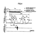
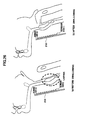
- Figure 3 is a view explaining the attachment of the pressure sensor 11 to the anterior region of the neck and the detection principle of the swallowing movement. Also, figure 4 is a view showing signal waves obtained from the pressure sensor 11, the myogenic potential electrometer electrode 12, and the microphone 13.
- the pressure sensor 11 is attached such that among three pairs of sensors, the lowest sensor is located in the normal position which position has no swallowing movement at the thyroid cartilage.
- the suprahyoid muscle group begins an activity as shown in the myogenic potential electrometer output (p1). Following it, the thyroid cartilage which is a part of the larynx begins to rise ( Figure 3 (a)). An output voltage of the pair 2 of the pressure sensor rises (p3); thereby, the pair 3 of the pressure sensor rises (p4) next. At the time of a movement to the lower part of the larynx, it is shown to that vice versa and the thyroid cartilage returns to the original position (p7). As shown in the output wave, after starting the pharynx rising, the swallowing sound obtained from the microphone is begun in a few seconds (p8).
- the pharynx movement, the electromyogram of the suprahyoid muscle group and the swallowing sound of the swallowing movement when food is swallowed are taken out as electrical signals with the swallowing movement measuring device.
- the capability to perform an analysis and an evaluation such as a change that occurs due to a kind of food or a difference by a person swallowing is expected.
- the present inventors studied whether the above swallowing movement measuring device can be utilized. As a result, the above measuring device was improved, and a device which can measure the larynx movement when a drink such as beer is swallowed continually with "glug, glug, glug, ". (hereinafter, it is described as "continuous swallowing movement") has been developed. That is, the present invention is an improvement of the above measuring device and is able to measure the continuous swallowing movement with "glug, glug, glug,", compared to the conventional measuring device which measures one swallowing movement.
- the larynx's position has vertical motion as above in the continuous swallowing movement, and it is recognized that the movement of the larynx cannot be accurately measured in the above conventional measuring device. Also, a position of the detecting element slips off by means of one swallowing movement and the measurement of the continuous movement is impossible for the attaching method of the detection element of the conventional measuring device. Therefore, in the present invention, the detecting element is improved, and the measurement of the continuous swallowing movement is possible. At the same time, the fixing method to a subject wearing the detecting element is improved, and an attaching position of the detecting element does not slip off due to the continuous swallowing movement.
- a continuous swallowing movement measuring device of the present invention comprising:
- a continuous swallowing movement measuring device comprises:
- a method for continuous swallowing movement comprises:
- a method for continuous swallowing movement comprises:
- a method for continuous swallowing movement comprises:
- a continuous swallowing movement measuring device comprises:
- the reflection type optical sensor has a light emitting element comprising an infrared light emitting diode and an infrared detection phototransistor.
- a method for continuous swallowing movement comprises:
- the measurement of the continuous swallowing movement is possible, and the same time, the attaching position of the detecting element does not slip off by means of the continuous swallowing movement, and the measurement of precise swallowing movement is enabled.
- the thyroid cartilage movement, the movement of the suprahyoid muscles group and swallowing sound at the time of continuously drinking beverages can be measured accurately. Also, applying these measured data to the evaluation and diagnosis of the swallowing movement of the subject contributes to a diagnosis capability for swallowing of a subject, as well as evaluation and development of food and drink.
- the continuous swallowing movement measuring device using a reflection type optical sensor by measuring the swallowing movement using an optical sensor with indirect pressure as opposed to the cervical part, wearing the cervical part of the measuring device disappears, and the swallowing movement can be measured in a more natural environment. Moreover, since each sensor is fixed on a fixed board, each sensor does not contact the laryngeal and sensors themselves do not move as the swallowing movement, so that the position of sensors is stable and the measurement with high accuracy can be attained.
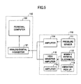
- FIG. 5 is a block structural view of a swallowing movement measuring device 100 which measures the swallowing movement of the embodiment of the present invention.
- the basic structure of the swallowing movement measuring device 100 of the embodiment of the present invention is the same as the swallowing movement measuring device 1 and it is composed of the measurement part 110 and the analysis part 120.
- the measurement part 110 has the pressure sensor 111, the small living body electrode 112, and the vibration pickup (microphone) 113.
- the pressure sensor 111, the small living body electrode 112, and the vibration pickup (microphone) 113 are connected to amplifiers 114, 115 and 116, respectively.
- the measurement part 110 is input to the personal computer 122 via the analog / digital converter 121 of the analysis part 120.
- the surface electrode of a myogenic potential electrometer 112 and the vibration pickup 113 are the same as in figure 1; the EMG surface electrode 112 is affixed to the equivalency region of the mylohyoid muscle of the digastric muscle, while reference electrodes (standard electrode) are attached to both earlobes.
- the vibration pickup 113 is attached such so as to be located beside the cricoid of the anterior region of the neck in order to measure the swallowing sound.
- FIG. 6 shows a tool for wearing the pressure sensor 130 to attach the pressure sensor 111 to the cervical part.
- the tool for wearing the pressure sensor 130 has a sensor fixture made of plastic 131 having a stand for the jaw 131a and a sensor mounting part 131b; urethane foam 132 is fixed at the sensor mounting part 131b, and a wearing band 134 is fixed at the sensor mounting part.
- Four pressure sensors s1, s2, s3 and s4 are fixed in a vertical direction at the central region of the front face of the urethane foam 132, and a both sides adhesive tape 133 is attached at both sides of the central region.
- the stand for the jaw 131a is supported by an axle 131c for rotating relative to the sensor mounting part 131b and can be adjusted for an angle of the plane of the stand for the jaw 131a.
- Fig. 7 shows the attached state of the tool for wearing the pressure sensor 130, the electrode for the electromyogram 112, and the vibration pickup 113 to a subject when the swallowing movement is measured using the swallowing movement measuring device 100 according to the present invention.
- wearing the pressure sensor 111 at the anterior region of the neck is performed using the tool for wearing the pressure sensor 130 shown in FIG. 6, but pressure sensors s1, s2, s3 and s4 which are fixed in the urethane foam 132 are placed on the anterior region of the neck.
- the sensor s1 which is placed on the lowest position is placed on the thyroid cartilage and the sensor s1 is fixed at the position by both sides adhesive tape 133 of the front of the urethane foam 132.
- the sensor s1 is fixed at the cervical part by using the wearing band 134 in this state.
- the jaw of a subject is placed on the stand for the jaw 131a.
- the position of the jaw is adjustable by placing the low repulsion urethane foam having appropriate depth between the jaw and the stand for jaw 131a. Also, as shown in figure 7, an elastic string attached to the stand for jaw 131a, an elastic string engaged with the ears, and a surface of the stand for the jaw 131a can be fixed.
- the surface electrode of a myogenic potential electrometer 112 is affixed to the equivalency region of the mylohyoid muscle of the digastric muscle, and the reference electrodes (standard electrodes) are attached to both earlobes.
- the vibration pickup 113 is attached at the narrow part of the neck located beside the cricoid.
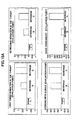
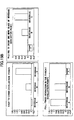
- Figures 8-10 show graphs of measurement data which were measured by the pressure sensor 111, the myogenic potential electrometer 112 and the vibration pickup 113, respectively. Also, the drinking time was about 10 seconds.
- Figure 8 represents the periodic up-and-down motion that is performed with the pharynx (the thyroid cartilage) when drink is drunk continually with "glug, glug, glug, ##.
- Figure 9 shows an output from the myogenic potential electrometer 115, and the motion of the suprahyoid muscle group appears periodically. Also, 2 signals appear, but they are 2 signals from the myogenic potential electrometer attached on the left and the right and show peaks appearing periodically.
- Figure 10 shows output waves from the vibration pickup 113, and at the same time, the swallowing sound is detected.
- the motion of the thyroid cartilage when a thing is swallowed is to move with the cover (the epiglottis) which does a change of the trachea and the esophagus, so that the thyroid cartilage goes up (from the trachea to the esophagus) when the thing is swallowed, then the thyroid cartilage returns to (from the esophagus to the trachea) the original position. Since the movement of the thyroid cartilage is changed where there is no bone close to the skin of the throat, the motion of the thyroid cartilage can be detected by the output of the pressure sensor 111 attached to the skin.
- Figure 11 shows outputs of pressure sensors s1, s2, s3 and s4 placed in line in the vertical direction in relation to the typical movement of the thyroid cartilage.
- the top position of the thyroid cartilage is placed at sensor s1 position (figure 11a), and the output of s1 is the highest level.
- the output of s2 also occurs, and the output level of s2 is lower than that of s1.
- the thyroid cartilage rises (figure 11b), and output data sequentially move to the sensors s2, s3 and s4.
- the thyroid cartilage moves in a range of an arrow shown in figure 11b.
- the thyroid cartilage moves in a range between the sensor s2 and s4, and output peaks of each sensor appear sequentially corresponding to its movement.
- changes of output of the above pressure sensors s1-s4 are also different depending on the fixing relationship between the thyroid cartilage and the pressure sensors s1-s4, but there is no change of the situation in that each sensor's output peak occurs sequentially depending on the movement of the thyroid cartilage at the time of the swallowing movement.
- the swallowing movement when drinking beverages continuously can be measured electrically.
- the pressure sensors s1-s4 are fixed on the tool for wearing the pressure sensor 130 having the above structure; thereby at the time of the continuous swallowing, the position of each sensor is not moved and changes of signals can be measured accurately. Therefore, the swallowing movement can be measured accurately.
- the beverage is water, juice or beer, etc.
- Inventors of the present invention considered the objective evaluation of feelings at the throat at the time of swallowing a drink, the easiness to swallow food and the drinkability by using the above swallowing movement measuring device 100.
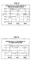
- a force of muscle active amount of the suprahyoid muscle group
- Figure 12 represents the average value of the muscle's active amount of 10 subjects for each beverage. It is recognized that the average value of the muscle's active amount of water is smaller than that of juice and beer and there is a significant difference between water and juice, also between water and beer based on the graph of figure 12. That is, more force is applied by the muscle at the time of drinking juice or beer rather than at the time of drinking water with "glug, glug, glug, .".
- the small amount of the muscle's active amount means easiness to drink, and from this point of view, it is recognized that beer and juice are hard to drink compared to the drinking water. On the other hand, since this hardness to drink shows active movement of the suprahyoid muscle group, it might be one of the elements when an index of "light finish sensation in the throat" and "full finish sensation in the throat” is established.
- figure 13 shows the results of average values of time periods of the swallowing sound (periods for which peaks appear in figure 10) obtained from the vibration pickup 113. It is recognized that there are significant differences between water and juice, also between water and beer. It is recognized that time periods of the swallowing sound are short at the time of drinking juice and beer rather than at the time of drinking water with "glug, glug, glug, ". That is, it was suggested that is more gurgling sound with "glug, glug, glug, " from the throat at the time of drinking juice and beer rather than at the time of drinking water.
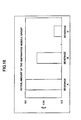
- Figure 14 is a result showing a relationship between the up and down time period of the thyroid cartilage obtained based on the measurement data from the pressure sensor 111 and beverage type.
- an evaluation of sense for being easy to drink was performed for 10 people of subjects concerning water, juice and beer (ordering for easiness to drink), and it shows a relationship between its order and the up and down time period of the thyroid cartilage.
- the first place was water
- the second place was juice
- the third place was beer. Comparing easy to drink and the up and down time period of the thyroid cartilage of the evaluation of sense, the longest period of the up and down time period of the thyroid cartilage was for beer, evaluated to be in third place, and it is recognized that for beer there is a significant difference from samples of the first place and the second place. Therefore, the up and down time period of the thyroid cartilage might be one possible element when an index of "easiness to drink" for beverages is established.
- the thyroid cartilage movement, the movement of the suprahyoid muscle group, and the swallowing sound at the time of continuously drinking beverages can be measured accurately. Also, applying these measured data to the evaluation and diagnosis of the swallowing movement of the subject can contribute to a diagnosis of the ability for swallowing of the subject, and evaluation and development of food and drink.
- the above example is the study of an active movement of the suprahyoid muscle group, time periods of the swallowing sound, and the up and down time periods of the thyroid cartilage for samples of beverages selected as natural water, juice and beer.
- a sample of beverage the example that a kind of alcoholic beverage having foaming properties is changed was performed and its result is explained.
- the alcoholic beverage having foaming properties beer A (beverage A), beer B (beverage B) and beer like an alcoholic beverage (beverage C) were selected as samples.
- characteristics of each sample were determined by sense examination.
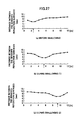
- figures 15A and 15B results of sense evaluation of 10 people as subjects about beverages A, B and C are shown.
- figure 15A "light finish sensation in the throat", “refreshing sensation in the throat”, “drinking with gurgle” and “good drinkability” were evaluated for respective beverages by each subject, and points were added and evaluated from -2 points to +2 points as the evaluation method.
- figure 15B shows results evaluated the same as in the above evaluation method about "easy to drink”, “willing to drink one more glass of beverage” and "full finish sensation in the throat”.
- the evaluations about being easy to drink like “easy to drink”, “light finish sensation in the throat”, “refreshing sensation in the throat”, “drinking with gurgle”, etc. are higher than those of the beverage A.
- the evaluation about "full finish sensation in the throat” is inferior to that of the beverage A, but is definitely superior to that of the beverage C. That is, it is clear that the beverage B has a characteristic which opposing evaluations of "easy to drink” and “full finish sensation in the throat" are moderately balanced.
- Figure 16 is a graph showing average values of the kinetic amount of the suprahyoid muscle group about each beverage A, B and C. According to the graph, when placing in order the active amount of the muscle of the throat at the time of drinking, the largest was the beverage A, the second largest was the beverage B and the last was the beverage C.
- the large kinetic amount of the suprahyoid muscle group predicts a relationship with "full finish sensation in the throat" or in reverse "easy to drink” of items of the above sense examination, so that it is recognized that the evaluation of "full finish sensation in the throat" of the beverage A, the evaluation of "easy to drink” of the beverage C and the kinetic amount of the suprahyoid muscle group have a relationship, and the relationship is very interesting.
- the figure 17 shows a graph which examined average values of time periods of the swallowing sound obtained from the vibration pickup.
- about time periods of the swallowing sound when the time period of the swallowing sound is short, it is shown that beverage flows down the throat smoothly at the time of drinking and it is predicted "easy to drink".
- the data of measurement there is no big difference among the data of beverages A, B and C, but the data of "full finish sensation in the throat" beverage A has the largest value. It is predicted that there is relevance with the data of the minimum value of the beverage C which is evaluated as the easiest to drink in the above sense examination.
- Figure 18 shows a result of examining the up and down time period of the thyroid cartilage obtained from the data of measurement of the pressure sensor 111.
- the period of the beverage C (beer-like alcoholic beverage) has the shortest period and the beverage A has the largest value; also the difference between the data of the beverage A and the data of the beverage B was small.
- the data of figure 18 can evaluate the smooth movement of the Adam's apple; it can be considered that the beverage flows down the throat smoothly when the time period is short.
- the period of "full finish sensation in the throat" beverage A (beer) has the longest period, and the relevance with the data which period of the beverage C evaluated as "easy to drink” has the shortest period is very interesting.
- the evaluation method for beverages sensuously with "full finish sensation in the throat", “drinkability”, “easy to drink”, etc., for beverages may become one of the indexes to express as data with numerical values objectively. Also, it may be used as an index of development of beverages and a quality indication of beverages. Also, the continuous swallowing movement measuring device of the above embodiment is explained about the example where the movement of the Adam's apple at the time of swallowing movement was picked up using plural pressure sensors. Next, the second example that the movement of the Adam's apple that swallowing movement is measured by using the small reflection type optical sensor that is a non-contact sensor instead of using pressure sensors is described below.
- the swallowing movement measuring system 200 is composed of a sensor part 210 comprising the reflection type optical sensor, a control circuit 220 and a data processing part 230.
- the system is such that a light is emitted from the optical sensor depending on an output pulse from a pulse generation circuit of the control circuit; the light reflected back with a reflector is detected in a light-receiving section of the optical sensor; the intensity of the light is detected by a voltage detection circuit and it is amplified, then it is input in a personal computer through an A/D converter; and distance from a sensor reflector is calculated based on the detection voltage, then it is displayed and analyzed.
- the sensor part 210 has a light emitting element 211 and a light receiving element 212, and the sensor part 210 is constructed such that the light emitted by the light emitting element 211 is irradiated in a measurement part, and the light reflected back by the measurement part is received in the light receiving element 212. Also, an infrared light emitting diode (LED) is used as the light emitting element 211 in the present example.
- LED infrared light emitting diode
- the control circuit 220 has the pulse generation circuit 221 and the detection circuit 222.
- the pulse generation circuit 221 is such that a rectangular wave is generated at a non-stable multi-vibrator, a period pulse having a period of 10 ms and a width of 0.1 ms is generated by inputting the rectangular wave in a single stable multi-vibrator, and a mirror constant electric current circuit is driven by this pulse so that the light emitting element (LED) 211 emits light.
- LED light emitting element
- the detection circuit 222 comprises the voltage detection circuit detecting the output voltage of the light receiving element (photo transistor) 212, and the detection circuit 222 consists of a sample holding circuit, a low pass filter (LPF) removing noise and a non-tuning amplification circuit which amplifies the detection voltage.
- LPF low pass filter
- the sample holding circuit samples the photo transistor output when the drive pulse is 1 and holds the photo transistor output when the drive pulse is 0. From the signal, sample pal and noise are removed by means of the primary LPF. In this case, the cutoff frequency was 140 Hz.
- the data processing part 230 has the A/D converter 231 and the personal computer 232.
- the output voltage detected at the detection circuit is transferred to the data processing part 230, then it is transferred to the personal computer 232 via the A/D converter 231 and processed there.
- Figures 20 and 21 show examination results of characteristics of the reflection type optical sensor 210 used in the present example.
- figure 20 shows a graph indicating a relationship between the distance and an output voltage of the sensor. As shown in the graph, the output voltage is dramatically decreased at the first stage as the distance increases, but after that, the output voltage is increased. The output was minimum around 1 mm distance.
- the optical sensor is attached at the anterior region of the neck and the swallowing movement is measured without contact, as described below. Considering the height of the thyroid cartilage, it is recognized that it is impossible to use the above characteristic of the output voltage for the measurement of the present invention.
- the distance between the sensor and the thyroid cartilage was set as about 5 mm at minimum; then a stable part of the characteristic of the output voltage of figure 20, in which the distance to the sensor's reflection surface is between 5 mm and 15 mm is used. In this range, a characteristic of the output voltage of the part for which the distance of the sensor's reflection surface is between 5 mm and 15 mm is shown in figure 21.
- Figure 21 shows a characteristic curve in which the horizontal axis indicates the output voltage and the vertical axis indicates the distance to the sensor's reflection surface.
- the swallowing movement measuring device attaching the above optical sensor to a human laryngeal for measuring is described.
- Figure 22 is a view showing the reflection type optical sensor used in the present example, and the reflection type optical sensor has lines connected to the light emitting element and the light receiving element.
- Figure 23 shows the sensor fixation board 251 of the optical sensor mounting device 250 for wearing the optical sensor shown in figure 22 on the anterior region of neck.
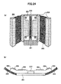
- FIG 24 shows whole view of the optical sensor mounting device 250.
- the optical sensor mounting device 250 comprises the sensor fixation board 251, the reflection type optical sensor 210 which is placed in a line and mounted on the board, and band 252 for fixing the sensor fixation board 251 on the anterior region of the neck.
- the sensor fixation board 251 a hard thing without a bend is used.
- Flexible plastic pads 253 are attached on both sides of the optical sensor 210 on the sensor fixation board 251.
- these pads 253 are such that the optical sensor 210 is held at a uniform distance from the surface of the laryngeal, that is, the optical sensor does not contact the laryngeal and also the optical sensor 210 is stably attached to the laryngeal.
- urethane foam pads for shading 254 are fixed along the line of the optical sensors on pads 253 thereby so that the approach of light to the optical sensor 251 is prevented.
- 12 sensors are used for the optical sensor 210.
- lines from the control circuit 220 are connected to each optical sensor 210; thereby the output voltage obtained from the light receiving element 212 by receiving the light is transferred to the data processing part.
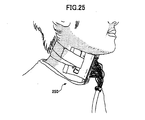
- Figure 25 shows the optical sensor mounting device 250 shown in figure 24 actually attached on the anterior region of the neck of a subject. Also, when the optical sensor mounting device 250 is attached to the laryngeal, as shown in figure 26, the optical sensor 210 is placed as a line on the position of the laryngeal, so that the lowest optical sensor among 12 sensors is placed in the neighborhood of the laryngeal. In this case, the same as the above, the distance between the optical sensor and the thyroid cartilage is the usual distance, which is 5 mm.
- Figure 26(a) shows a position of the larynx before the swallowing movement
- Figure 26(b) shows the position of the larynx after the swallowing movement.
- Figure 27 shows a change of the output of 12 optical sensors at the time of drinking the beverages in succession by the progress of time (a)-(b).
- (a) shows the status before the swallowing and at an arrow position, the distance between the sensor and the surface of the reflector (that is the anterior region of neck) is the shortest, thereby it indicates that the larynx is positioned at this part.
- (b) shows the status after starting the swallowing movement; the position where the sensor and the larynx came closest is moved to an arrow position. That is, it is recognized that the larynx moved above while swallowing occurred.
- (c) shows the status after starting the swallowing movement; the larynx is placed at the highest position. Also, changes between (b) and (c) of figure 27 are repeatedly observed at the time of drinking the beverages in succession.
- the swallowing movement measuring device 200 with the reflection type optical sensor of the present example the same as using the swallowing movement measuring device 100 with the above pressure sensor, it is possible that the performance or evaluation of the swallowing movement of a subject can be examined.
- the swallowing movement by indirectly measuring the swallowing movement using optical sensors, using pressure and wearing the cervical part of the measuring device disappear, and the swallowing movement can be measured in a more natural environment. Moreover, since each sensor is fixed on the fixation board so that the sensors do not contact the laryngeal and the sensors themselves do not move with the swallowing movement, the position of sensors is stable and measurement with high accuracy can be achieved.
- the swallowing movement measuring device with the above optical sensors can be used for providing the detection means like the myogenic potential electrometer or the vibration pickup, the same as the above example. Also, even though the continuous swallowing movement measuring device may have any one of the examination means, it is made without departing from the scope of the present invention.
Landscapes
- Health & Medical Sciences (AREA)
- Life Sciences & Earth Sciences (AREA)
- Molecular Biology (AREA)
- Veterinary Medicine (AREA)
- Public Health (AREA)
- General Health & Medical Sciences (AREA)
- Animal Behavior & Ethology (AREA)
- Surgery (AREA)
- Engineering & Computer Science (AREA)
- Biomedical Technology (AREA)
- Heart & Thoracic Surgery (AREA)
- Medical Informatics (AREA)
- Biophysics (AREA)
- Pathology (AREA)
- Physics & Mathematics (AREA)
- Physiology (AREA)
- Gastroenterology & Hepatology (AREA)
- Endocrinology (AREA)
- Rheumatology (AREA)
- Dentistry (AREA)
- Oral & Maxillofacial Surgery (AREA)
- Measurement Of The Respiration, Hearing Ability, Form, And Blood Characteristics Of Living Organisms (AREA)
- Force Measurement Appropriate To Specific Purposes (AREA)
- Length Measuring Devices With Unspecified Measuring Means (AREA)
Applications Claiming Priority (4)
| Application Number | Priority Date | Filing Date | Title |
|---|---|---|---|
| JP2004229079 | 2004-08-05 | ||
| JP2004255966 | 2004-09-02 | ||
| JP2005042545A JP4727253B2 (ja) | 2004-08-05 | 2005-02-18 | 連続嚥下運動測定装置及び連続嚥下運動測定方法 |
| PCT/JP2005/013969 WO2006013797A1 (ja) | 2004-08-05 | 2005-07-29 | 連続嚥下運動測定装置及び連続嚥下運動測定方法 |
Publications (3)
| Publication Number | Publication Date |
|---|---|
| EP1787582A1 true EP1787582A1 (de) | 2007-05-23 |
| EP1787582A4 EP1787582A4 (de) | 2008-02-27 |
| EP1787582B1 EP1787582B1 (de) | 2011-10-12 |
Family
ID=35787083
Family Applications (1)
| Application Number | Title | Priority Date | Filing Date |
|---|---|---|---|
| EP05767122A Not-in-force EP1787582B1 (de) | 2004-08-05 | 2005-07-29 | Vorrichtung und verfahren zum messen von kontinuierlicher schluckbewegung |
Country Status (7)
| Country | Link |
|---|---|
| US (1) | US8211040B2 (de) |
| EP (1) | EP1787582B1 (de) |
| JP (1) | JP4727253B2 (de) |
| AT (1) | ATE527936T1 (de) |
| CA (1) | CA2575958C (de) |
| DK (1) | DK1787582T3 (de) |
| WO (1) | WO2006013797A1 (de) |
Cited By (7)
| Publication number | Priority date | Publication date | Assignee | Title |
|---|---|---|---|---|
| EP2100559A1 (de) * | 2008-03-10 | 2009-09-16 | Hitachi Computer Peripherals Co., Ltd. | Vorrichtung zur Untersuchung eines lebenden Körpers |
| US7651470B2 (en) * | 2006-03-29 | 2010-01-26 | Sumitomo Osaka Cement Co., Ltd. | Swallowing function evaluating apparatus |
| FR2956574A1 (fr) * | 2010-02-19 | 2011-08-26 | Yves Albert Jean Marie Launay | Dispositif extrabuccal destine a tester, chez l'etre humain, le type de deglutition presente par l'individu et a concourir a la reeducation des deglutitions atypiques |
| WO2017030514A2 (en) | 2015-08-19 | 2017-02-23 | Numan Demir | A swallowing exercise apparatus |
| CN107920781A (zh) * | 2015-08-21 | 2018-04-17 | 住友电气工业株式会社 | 吞咽运动监测传感器 |
| EP3395249A4 (de) * | 2015-12-24 | 2019-05-08 | Bando Chemical Industries, Ltd. | Schluckbewegungmessvorrichtung und schluckbewegungmessverfahren |
| EP3498165A4 (de) * | 2016-08-15 | 2020-05-06 | University of Tsukuba | Vorrichtung zur messung des schluckvorgangs und system zur unterstützung des schluckvorgangs |
Families Citing this family (52)
| Publication number | Priority date | Publication date | Assignee | Title |
|---|---|---|---|---|
| JP4727253B2 (ja) | 2004-08-05 | 2011-07-20 | サッポロビール株式会社 | 連続嚥下運動測定装置及び連続嚥下運動測定方法 |
| JP5081860B2 (ja) * | 2004-08-05 | 2012-11-28 | サッポロビール株式会社 | 連続嚥下運動測定装置及び連続嚥下運動測定方法 |
| AR056739A1 (es) * | 2006-10-30 | 2007-10-24 | Tecn Conicet Consejo Nac De In | Metodo para la detectar la deglucion de un bebe empleando parametros fisicos de la deglucion ( sonidos , movimientos etc ) apareados en el tiempo (time locked) con la actividad motora oral nutritiva de la succion y dispositivo de diagnostico y registro de la coordinacion de succion, deglucion y resp |
| JP5022782B2 (ja) | 2007-06-05 | 2012-09-12 | 株式会社日立製作所 | 生体検査装置 |
| JP4702860B2 (ja) * | 2007-07-18 | 2011-06-15 | キリンホールディングス株式会社 | 嚥下感覚の簡易測定方法 |
| US8989837B2 (en) | 2009-12-01 | 2015-03-24 | Kyma Medical Technologies Ltd. | Methods and systems for determining fluid content of tissue |
| US9757595B2 (en) * | 2008-10-14 | 2017-09-12 | Theraclion Sa | Systems and methods for synchronizing ultrasound treatment of thryoid and parathyroid with movements of patients |
| US8353832B2 (en) * | 2008-10-14 | 2013-01-15 | Theraclion | Systems and methods for ultrasound treatment of thyroid and parathyroid |
| US8267875B2 (en) * | 2008-10-29 | 2012-09-18 | Tom Chau | Method and system of segmentation and time duration analysis of dual-axis swallowing accelerometry signals |
| US8992446B2 (en) * | 2009-06-21 | 2015-03-31 | Holland Bloorview Kids Rehabilitation Hospital | Procedure for denoising dual-axis swallowing accelerometry signals |
| EP2595532A4 (de) | 2010-07-21 | 2014-04-09 | Kyma Medical Technologies Ltd | Implantierbares dielektrometer |
| JP5780583B2 (ja) * | 2011-01-04 | 2015-09-16 | 株式会社明治 | 食感の生理学的評価装置 |
| US20120259554A1 (en) * | 2011-04-08 | 2012-10-11 | Sony Computer Entertainment Inc. | Tongue tracking interface apparatus and method for controlling a computer program |
| US10006896B2 (en) * | 2011-11-14 | 2018-06-26 | University of Pittsburgh—of the Commonwealth System of Higher Education | Method, apparatus and system for food intake and physical activity assessment |
| US20210249116A1 (en) * | 2012-06-14 | 2021-08-12 | Medibotics Llc | Smart Glasses and Wearable Systems for Measuring Food Consumption |
| IN2014DN10262A (de) | 2012-06-19 | 2015-08-07 | Nestec Sa | |
| JP2015526258A (ja) | 2012-08-31 | 2015-09-10 | ユニバーシティ オブ フロリダ リサーチ ファンデーション インコーポレーティッド | 咳及び嚥下のコントロール |
| US9042992B2 (en) | 2012-08-31 | 2015-05-26 | University Of Florida Research Foundation, Inc. | Protecting airways |
| KR101492404B1 (ko) | 2013-02-20 | 2015-02-16 | 우송대학교 산학협력단 | 삼킴 근육 훈련용 기기 |
| US8958578B2 (en) * | 2013-07-02 | 2015-02-17 | Yi Chuan Chen | Throat vibration audio wireless transmission apparatus |
| US10680324B2 (en) | 2013-10-29 | 2020-06-09 | Zoll Medical Israel Ltd. | Antenna systems and devices and methods of manufacture thereof |
| US11013420B2 (en) | 2014-02-05 | 2021-05-25 | Zoll Medical Israel Ltd. | Systems, apparatuses and methods for determining blood pressure |
| EP4364641A2 (de) * | 2014-04-09 | 2024-05-08 | Société des Produits Nestlé S.A. | Technik zur bestimmung eines schluckmangels |
| JP5995904B2 (ja) * | 2014-04-30 | 2016-09-21 | シャープ株式会社 | 人体装着型計測装置 |
| JP5784180B1 (ja) * | 2014-04-30 | 2015-09-24 | シャープ株式会社 | 人体装着型計測装置及び計測方法 |
| WO2015179950A1 (en) * | 2014-05-24 | 2015-12-03 | Rieger Jana Maureen | Systems and methods for diagnosis and treatment of swallowing disorders |
| CN104127188A (zh) * | 2014-08-08 | 2014-11-05 | 沈迪 | 一种颈部运动量监控方法及设备 |
| US11259715B2 (en) | 2014-09-08 | 2022-03-01 | Zoll Medical Israel Ltd. | Monitoring and diagnostics systems and methods |
| US10488264B2 (en) * | 2014-09-11 | 2019-11-26 | Ams Sensors Singapore Pte. Ltd. | Determining spectral emission characteristics of incident radiation |
| JP6742688B2 (ja) * | 2014-12-27 | 2020-08-19 | 三栄源エフ・エフ・アイ株式会社 | 飲料の評価及びその応用 |
| JP6775951B2 (ja) * | 2014-12-27 | 2020-10-28 | 三栄源エフ・エフ・アイ株式会社 | 飲食物の嚥下感覚の評価方法 |
| US10548485B2 (en) | 2015-01-12 | 2020-02-04 | Zoll Medical Israel Ltd. | Systems, apparatuses and methods for radio frequency-based attachment sensing |
| JP2017038840A (ja) * | 2015-08-21 | 2017-02-23 | 住友電気工業株式会社 | 嚥下運動モニタリングセンサ |
| JP6692110B2 (ja) * | 2015-11-06 | 2020-05-13 | 国立大学法人東北大学 | 味覚評価診断装置 |
| JP2018130199A (ja) * | 2017-02-14 | 2018-08-23 | 学校法人昭和大学 | 嚥下検出装置 |
| WO2018180779A1 (ja) * | 2017-03-29 | 2018-10-04 | 株式会社村田製作所 | 嚥下解析システム |
| JP6645619B2 (ja) | 2017-03-29 | 2020-02-14 | 株式会社村田製作所 | 嚥下センサ |
| WO2019030746A1 (en) | 2017-08-10 | 2019-02-14 | Zoll Medical Israel Ltd. | SYSTEMS, DEVICES AND METHODS FOR PHYSIOLOGICAL MONITORING OF PATIENTS |
| JP7028432B2 (ja) * | 2017-09-20 | 2022-03-02 | 国立大学法人 筑波大学 | 支援装置 |
| DE102018010332A1 (de) | 2018-03-05 | 2020-01-16 | Ion Suberviola | Schluckbewegungs-Erfassungssystem |
| DE102018001747B4 (de) | 2018-03-05 | 2019-12-05 | Ion Suberviola | Schluckbewegungs-Erfassungssystem |
| JP7075804B2 (ja) * | 2018-04-16 | 2022-05-26 | 長谷川香料株式会社 | 飲食品の風味の好ましさの解析方法および予測方法 |
| EP3598933A1 (de) * | 2018-06-26 | 2020-01-29 | Koninklijke Philips N.V. | Überwachung des schluckens in einer person |
| JP7207898B2 (ja) * | 2018-08-20 | 2023-01-18 | 長谷川香料株式会社 | 飲食品の嚥下感覚の解析方法および予測方法 |
| JP2020089613A (ja) * | 2018-12-07 | 2020-06-11 | 国立大学法人山梨大学 | 嚥下能力測定システム、嚥下能力測定方法およびセンサホルダ |
| JP2020099655A (ja) * | 2018-12-21 | 2020-07-02 | 鉄男 菊池 | 健康装置 高齢者ならびに介護利用者や寝たきり老人など誤飲する可能性のある人に予防可能なシステム装置。 |
| JP2021010674A (ja) * | 2019-07-09 | 2021-02-04 | 株式会社日立製作所 | 生体検査装置 |
| JP7281367B2 (ja) * | 2019-08-27 | 2023-05-25 | 長谷川香料株式会社 | 飲食品評価装置および飲食品評価方法 |
| JP2021062133A (ja) * | 2019-10-16 | 2021-04-22 | スターメディカル株式会社 | 嚥下機能計測装置及び嚥下機能計測システム |
| CN110960214B (zh) * | 2019-12-20 | 2022-07-19 | 首都医科大学附属北京同仁医院 | 一种表面肌电图同步音频信号采集方法及设备 |
| EP4306933A1 (de) | 2021-03-12 | 2024-01-17 | San-Ei Gen F.F.I., INC. | Verfahren zur beurteilung des mundgefühls beim schlucken von lebensmitteln oder getränken und verfahren zur herstellung einer formulierung zur verbesserung des schluckgefühls |
| CN116942099B (zh) * | 2023-07-31 | 2024-03-19 | 华南理工大学 | 一种基于肌电和压力传感的吞咽监测系统及方法 |
Citations (3)
| Publication number | Priority date | Publication date | Assignee | Title |
|---|---|---|---|---|
| US4629424A (en) * | 1984-08-30 | 1986-12-16 | Integrated Ionics, Inc. | Intraoral ambient sensing device |
| EP0444594A1 (de) * | 1990-03-01 | 1991-09-04 | Shirit Yarkony | Verfahren und Gerät zur Anzeige und Auswertung der Schluckbewegung eines Patienten |
| FR2800266A1 (fr) * | 1999-10-29 | 2001-05-04 | Richard Sauveur Arini | Appareil concu pour ameliorer le processus masticatoire en vue de perdre des kilos superflus et en general pour ameliorer la sante |
Family Cites Families (5)
| Publication number | Priority date | Publication date | Assignee | Title |
|---|---|---|---|---|
| DE2814551C2 (de) * | 1978-04-04 | 1986-03-13 | Siemens AG, 1000 Berlin und 8000 München | Vorrichtung zur Messung des Ortes, der Lage und/oder der Orts- bzw. Lageänderung eines starren Körpers im Raum |
| JP3093828B2 (ja) | 1991-08-08 | 2000-10-03 | ヤルコニー シリット | のみ込む機能の障害の分析及び処置 |
| US6461589B2 (en) * | 1999-08-27 | 2002-10-08 | Wisconsin Alumni Research Foundation | Standardized compositions which facilitate swallowing in dysphagic subjects |
| JP2003111748A (ja) * | 2001-10-04 | 2003-04-15 | Nippon Riko Igaku Kenkyusho:Kk | 嚥下音採取装置 |
| JP4727253B2 (ja) | 2004-08-05 | 2011-07-20 | サッポロビール株式会社 | 連続嚥下運動測定装置及び連続嚥下運動測定方法 |
-
2005
- 2005-02-18 JP JP2005042545A patent/JP4727253B2/ja not_active Expired - Fee Related
- 2005-07-29 AT AT05767122T patent/ATE527936T1/de not_active IP Right Cessation
- 2005-07-29 CA CA2575958A patent/CA2575958C/en not_active Expired - Fee Related
- 2005-07-29 WO PCT/JP2005/013969 patent/WO2006013797A1/ja active Application Filing
- 2005-07-29 EP EP05767122A patent/EP1787582B1/de not_active Not-in-force
- 2005-07-29 DK DK05767122.4T patent/DK1787582T3/da active
- 2005-07-29 US US11/659,421 patent/US8211040B2/en not_active Expired - Fee Related
Patent Citations (3)
| Publication number | Priority date | Publication date | Assignee | Title |
|---|---|---|---|---|
| US4629424A (en) * | 1984-08-30 | 1986-12-16 | Integrated Ionics, Inc. | Intraoral ambient sensing device |
| EP0444594A1 (de) * | 1990-03-01 | 1991-09-04 | Shirit Yarkony | Verfahren und Gerät zur Anzeige und Auswertung der Schluckbewegung eines Patienten |
| FR2800266A1 (fr) * | 1999-10-29 | 2001-05-04 | Richard Sauveur Arini | Appareil concu pour ameliorer le processus masticatoire en vue de perdre des kilos superflus et en general pour ameliorer la sante |
Non-Patent Citations (1)
| Title |
|---|
| See also references of WO2006013797A1 * |
Cited By (11)
| Publication number | Priority date | Publication date | Assignee | Title |
|---|---|---|---|---|
| US7651470B2 (en) * | 2006-03-29 | 2010-01-26 | Sumitomo Osaka Cement Co., Ltd. | Swallowing function evaluating apparatus |
| EP2100559A1 (de) * | 2008-03-10 | 2009-09-16 | Hitachi Computer Peripherals Co., Ltd. | Vorrichtung zur Untersuchung eines lebenden Körpers |
| US8118758B2 (en) | 2008-03-10 | 2012-02-21 | Hitachi Computer Peripherals Co., Ltd. | Living body inspection apparatus |
| FR2956574A1 (fr) * | 2010-02-19 | 2011-08-26 | Yves Albert Jean Marie Launay | Dispositif extrabuccal destine a tester, chez l'etre humain, le type de deglutition presente par l'individu et a concourir a la reeducation des deglutitions atypiques |
| WO2017030514A2 (en) | 2015-08-19 | 2017-02-23 | Numan Demir | A swallowing exercise apparatus |
| WO2017030514A3 (en) * | 2015-08-19 | 2017-03-23 | Numan Demir | A swallowing exercise apparatus |
| CN107920781A (zh) * | 2015-08-21 | 2018-04-17 | 住友电气工业株式会社 | 吞咽运动监测传感器 |
| EP3338630A4 (de) * | 2015-08-21 | 2019-04-17 | Sumitomo Electric Industries, Ltd. | Schluckbewegungsüberwachungssensor |
| EP3395249A4 (de) * | 2015-12-24 | 2019-05-08 | Bando Chemical Industries, Ltd. | Schluckbewegungmessvorrichtung und schluckbewegungmessverfahren |
| EP3498165A4 (de) * | 2016-08-15 | 2020-05-06 | University of Tsukuba | Vorrichtung zur messung des schluckvorgangs und system zur unterstützung des schluckvorgangs |
| US11369308B2 (en) | 2016-08-15 | 2022-06-28 | Plimes Inc. | Swallowing action measurement device and swallowing action support system |
Also Published As
| Publication number | Publication date |
|---|---|
| US20090030346A1 (en) | 2009-01-29 |
| ATE527936T1 (de) | 2011-10-15 |
| WO2006013797A1 (ja) | 2006-02-09 |
| CA2575958C (en) | 2011-05-17 |
| CA2575958A1 (en) | 2006-02-09 |
| EP1787582A4 (de) | 2008-02-27 |
| JP4727253B2 (ja) | 2011-07-20 |
| JP2006095264A (ja) | 2006-04-13 |
| DK1787582T3 (da) | 2012-01-02 |
| EP1787582B1 (de) | 2011-10-12 |
| US8211040B2 (en) | 2012-07-03 |
Similar Documents
| Publication | Publication Date | Title |
|---|---|---|
| CA2575958C (en) | A continuous swallowing movement measuring device and method for measuring a continuous swallowing movement | |
| JP5355622B2 (ja) | 飲料評価方法 | |
| Stone | A guide to analysing tongue motion from ultrasound images | |
| US11559247B2 (en) | Apparatuses for detecting and/or diagnosing swallowing disorders | |
| EP2100559B1 (de) | Vorrichtung zur Untersuchung eines lebenden Körpers | |
| Sazonov et al. | A sensor system for automatic detection of food intake through non-invasive monitoring of chewing | |
| US8287470B2 (en) | Swallowing test apparatus | |
| Li et al. | Development of a system to monitor laryngeal movement during swallowing using a bend sensor | |
| JP2012075758A (ja) | 嚥下障害検出システム | |
| JP4915024B2 (ja) | 嚥下機能評価装置、嚥下機能評価装置操作方法、嚥下機能評価装置操作プログラムおよびコンピュータで読み取り可能な記録媒体並びに記憶した機器 | |
| Taniguchi et al. | Earable RCC: development of an earphone‐type reliable chewing‐count measurement device | |
| JP6073709B2 (ja) | センサシート、嚥下活動測定装置及び嚥下活動測定方法 | |
| EP2861150B1 (de) | Überwachungssystem zur überwachung von herzsignalen | |
| JP2012200300A (ja) | 嚥下運動測定システム | |
| Iizuka et al. | A new flexible piezoelectric pressure sensor array for the noninvasive detection of laryngeal movement during swallowing | |
| Liu et al. | In situ quantitative assessment of food oral processing parameters: A review of feasible techniques and devices | |
| CN1903123A (zh) | 运动机能检查装置 | |
| US20230270375A1 (en) | Ultrasound diagnostic apparatus and control method for ultrasound diagnostic apparatus | |
| JP2004261482A (ja) | 人体背骨測定表示システム | |
| Lopez-Meyer | Automatic detection and classification of food intake |
Legal Events
| Date | Code | Title | Description |
|---|---|---|---|
| PUAI | Public reference made under article 153(3) epc to a published international application that has entered the european phase |
Free format text: ORIGINAL CODE: 0009012 |
|
| 17P | Request for examination filed |
Effective date: 20070228 |
|
| AK | Designated contracting states |
Kind code of ref document: A1 Designated state(s): AT BE BG CH CY CZ DE DK EE ES FI FR GB GR HU IE IS IT LI LT LU LV MC NL PL PT RO SE SI SK TR |
|
| DAX | Request for extension of the european patent (deleted) | ||
| A4 | Supplementary search report drawn up and despatched |
Effective date: 20080124 |
|
| 17Q | First examination report despatched |
Effective date: 20080515 |
|
| GRAP | Despatch of communication of intention to grant a patent |
Free format text: ORIGINAL CODE: EPIDOSNIGR1 |
|
| GRAS | Grant fee paid |
Free format text: ORIGINAL CODE: EPIDOSNIGR3 |
|
| GRAA | (expected) grant |
Free format text: ORIGINAL CODE: 0009210 |
|
| AK | Designated contracting states |
Kind code of ref document: B1 Designated state(s): AT BE BG CH CY CZ DE DK EE ES FI FR GB GR HU IE IS IT LI LT LU LV MC NL PL PT RO SE SI SK TR |
|
| REG | Reference to a national code |
Ref country code: GB Ref legal event code: FG4D |
|
| REG | Reference to a national code |
Ref country code: CH Ref legal event code: EP |
|
| REG | Reference to a national code |
Ref country code: IE Ref legal event code: FG4D |
|
| REG | Reference to a national code |
Ref country code: DE Ref legal event code: R096 Ref document number: 602005030594 Country of ref document: DE Effective date: 20111215 |
|
| REG | Reference to a national code |
Ref country code: DK Ref legal event code: T3 |
|
| REG | Reference to a national code |
Ref country code: NL Ref legal event code: T3 |
|
| LTIE | Lt: invalidation of european patent or patent extension |
Effective date: 20111012 |
|
| REG | Reference to a national code |
Ref country code: AT Ref legal event code: MK05 Ref document number: 527936 Country of ref document: AT Kind code of ref document: T Effective date: 20111012 |
|
| PG25 | Lapsed in a contracting state [announced via postgrant information from national office to epo] |
Ref country code: BE Free format text: LAPSE BECAUSE OF FAILURE TO SUBMIT A TRANSLATION OF THE DESCRIPTION OR TO PAY THE FEE WITHIN THE PRESCRIBED TIME-LIMIT Effective date: 20111012 Ref country code: LT Free format text: LAPSE BECAUSE OF FAILURE TO SUBMIT A TRANSLATION OF THE DESCRIPTION OR TO PAY THE FEE WITHIN THE PRESCRIBED TIME-LIMIT Effective date: 20111012 Ref country code: IS Free format text: LAPSE BECAUSE OF FAILURE TO SUBMIT A TRANSLATION OF THE DESCRIPTION OR TO PAY THE FEE WITHIN THE PRESCRIBED TIME-LIMIT Effective date: 20120212 |
|
| PG25 | Lapsed in a contracting state [announced via postgrant information from national office to epo] |
Ref country code: PT Free format text: LAPSE BECAUSE OF FAILURE TO SUBMIT A TRANSLATION OF THE DESCRIPTION OR TO PAY THE FEE WITHIN THE PRESCRIBED TIME-LIMIT Effective date: 20120213 Ref country code: LV Free format text: LAPSE BECAUSE OF FAILURE TO SUBMIT A TRANSLATION OF THE DESCRIPTION OR TO PAY THE FEE WITHIN THE PRESCRIBED TIME-LIMIT Effective date: 20111012 Ref country code: SE Free format text: LAPSE BECAUSE OF FAILURE TO SUBMIT A TRANSLATION OF THE DESCRIPTION OR TO PAY THE FEE WITHIN THE PRESCRIBED TIME-LIMIT Effective date: 20111012 Ref country code: GR Free format text: LAPSE BECAUSE OF FAILURE TO SUBMIT A TRANSLATION OF THE DESCRIPTION OR TO PAY THE FEE WITHIN THE PRESCRIBED TIME-LIMIT Effective date: 20120113 Ref country code: SI Free format text: LAPSE BECAUSE OF FAILURE TO SUBMIT A TRANSLATION OF THE DESCRIPTION OR TO PAY THE FEE WITHIN THE PRESCRIBED TIME-LIMIT Effective date: 20111012 |
|
| PG25 | Lapsed in a contracting state [announced via postgrant information from national office to epo] |
Ref country code: CY Free format text: LAPSE BECAUSE OF FAILURE TO SUBMIT A TRANSLATION OF THE DESCRIPTION OR TO PAY THE FEE WITHIN THE PRESCRIBED TIME-LIMIT Effective date: 20111012 |
|
| PG25 | Lapsed in a contracting state [announced via postgrant information from national office to epo] |
Ref country code: BG Free format text: LAPSE BECAUSE OF FAILURE TO SUBMIT A TRANSLATION OF THE DESCRIPTION OR TO PAY THE FEE WITHIN THE PRESCRIBED TIME-LIMIT Effective date: 20120112 Ref country code: SK Free format text: LAPSE BECAUSE OF FAILURE TO SUBMIT A TRANSLATION OF THE DESCRIPTION OR TO PAY THE FEE WITHIN THE PRESCRIBED TIME-LIMIT Effective date: 20111012 Ref country code: EE Free format text: LAPSE BECAUSE OF FAILURE TO SUBMIT A TRANSLATION OF THE DESCRIPTION OR TO PAY THE FEE WITHIN THE PRESCRIBED TIME-LIMIT Effective date: 20111012 Ref country code: CZ Free format text: LAPSE BECAUSE OF FAILURE TO SUBMIT A TRANSLATION OF THE DESCRIPTION OR TO PAY THE FEE WITHIN THE PRESCRIBED TIME-LIMIT Effective date: 20111012 |
|
| PLBE | No opposition filed within time limit |
Free format text: ORIGINAL CODE: 0009261 |
|
| STAA | Information on the status of an ep patent application or granted ep patent |
Free format text: STATUS: NO OPPOSITION FILED WITHIN TIME LIMIT |
|
| PG25 | Lapsed in a contracting state [announced via postgrant information from national office to epo] |
Ref country code: PL Free format text: LAPSE BECAUSE OF FAILURE TO SUBMIT A TRANSLATION OF THE DESCRIPTION OR TO PAY THE FEE WITHIN THE PRESCRIBED TIME-LIMIT Effective date: 20111012 Ref country code: RO Free format text: LAPSE BECAUSE OF FAILURE TO SUBMIT A TRANSLATION OF THE DESCRIPTION OR TO PAY THE FEE WITHIN THE PRESCRIBED TIME-LIMIT Effective date: 20111012 Ref country code: IT Free format text: LAPSE BECAUSE OF FAILURE TO SUBMIT A TRANSLATION OF THE DESCRIPTION OR TO PAY THE FEE WITHIN THE PRESCRIBED TIME-LIMIT Effective date: 20111012 |
|
| 26N | No opposition filed |
Effective date: 20120713 |
|
| PGFP | Annual fee paid to national office [announced via postgrant information from national office to epo] |
Ref country code: GB Payment date: 20120725 Year of fee payment: 8 |
|
| REG | Reference to a national code |
Ref country code: DE Ref legal event code: R097 Ref document number: 602005030594 Country of ref document: DE Effective date: 20120713 |
|
| PGFP | Annual fee paid to national office [announced via postgrant information from national office to epo] |
Ref country code: FR Payment date: 20120719 Year of fee payment: 8 Ref country code: DE Payment date: 20120725 Year of fee payment: 8 |
|
| PG25 | Lapsed in a contracting state [announced via postgrant information from national office to epo] |
Ref country code: AT Free format text: LAPSE BECAUSE OF FAILURE TO SUBMIT A TRANSLATION OF THE DESCRIPTION OR TO PAY THE FEE WITHIN THE PRESCRIBED TIME-LIMIT Effective date: 20111012 |
|
| PGFP | Annual fee paid to national office [announced via postgrant information from national office to epo] |
Ref country code: NL Payment date: 20120714 Year of fee payment: 8 |
|
| PG25 | Lapsed in a contracting state [announced via postgrant information from national office to epo] |
Ref country code: MC Free format text: LAPSE BECAUSE OF NON-PAYMENT OF DUE FEES Effective date: 20120731 |
|
| REG | Reference to a national code |
Ref country code: CH Ref legal event code: PL |
|
| PG25 | Lapsed in a contracting state [announced via postgrant information from national office to epo] |
Ref country code: ES Free format text: LAPSE BECAUSE OF FAILURE TO SUBMIT A TRANSLATION OF THE DESCRIPTION OR TO PAY THE FEE WITHIN THE PRESCRIBED TIME-LIMIT Effective date: 20120123 Ref country code: CH Free format text: LAPSE BECAUSE OF NON-PAYMENT OF DUE FEES Effective date: 20120731 Ref country code: LI Free format text: LAPSE BECAUSE OF NON-PAYMENT OF DUE FEES Effective date: 20120731 |
|
| REG | Reference to a national code |
Ref country code: IE Ref legal event code: MM4A |
|
| PG25 | Lapsed in a contracting state [announced via postgrant information from national office to epo] |
Ref country code: FI Free format text: LAPSE BECAUSE OF FAILURE TO SUBMIT A TRANSLATION OF THE DESCRIPTION OR TO PAY THE FEE WITHIN THE PRESCRIBED TIME-LIMIT Effective date: 20111012 |
|
| PG25 | Lapsed in a contracting state [announced via postgrant information from national office to epo] |
Ref country code: IE Free format text: LAPSE BECAUSE OF NON-PAYMENT OF DUE FEES Effective date: 20120729 |
|
| REG | Reference to a national code |
Ref country code: NL Ref legal event code: V1 Effective date: 20140201 |
|
| REG | Reference to a national code |
Ref country code: DK Ref legal event code: EBP Effective date: 20130731 |
|
| GBPC | Gb: european patent ceased through non-payment of renewal fee |
Effective date: 20130729 |
|
| REG | Reference to a national code |
Ref country code: DE Ref legal event code: R119 Ref document number: 602005030594 Country of ref document: DE Effective date: 20140201 |
|
| REG | Reference to a national code |
Ref country code: FR Ref legal event code: ST Effective date: 20140331 |
|
| PG25 | Lapsed in a contracting state [announced via postgrant information from national office to epo] |
Ref country code: NL Free format text: LAPSE BECAUSE OF NON-PAYMENT OF DUE FEES Effective date: 20140201 Ref country code: DE Free format text: LAPSE BECAUSE OF NON-PAYMENT OF DUE FEES Effective date: 20140201 Ref country code: TR Free format text: LAPSE BECAUSE OF FAILURE TO SUBMIT A TRANSLATION OF THE DESCRIPTION OR TO PAY THE FEE WITHIN THE PRESCRIBED TIME-LIMIT Effective date: 20111012 Ref country code: GB Free format text: LAPSE BECAUSE OF NON-PAYMENT OF DUE FEES Effective date: 20130729 |
|
| PG25 | Lapsed in a contracting state [announced via postgrant information from national office to epo] |
Ref country code: FR Free format text: LAPSE BECAUSE OF NON-PAYMENT OF DUE FEES Effective date: 20130731 Ref country code: LU Free format text: LAPSE BECAUSE OF NON-PAYMENT OF DUE FEES Effective date: 20120729 |
|
| PG25 | Lapsed in a contracting state [announced via postgrant information from national office to epo] |
Ref country code: HU Free format text: LAPSE BECAUSE OF FAILURE TO SUBMIT A TRANSLATION OF THE DESCRIPTION OR TO PAY THE FEE WITHIN THE PRESCRIBED TIME-LIMIT Effective date: 20050729 |
|
| PG25 | Lapsed in a contracting state [announced via postgrant information from national office to epo] |
Ref country code: DK Free format text: LAPSE BECAUSE OF NON-PAYMENT OF DUE FEES Effective date: 20130731 |