EP1787481B1 - Anschlussmodul für die telekommunikations- und datentechnik - Google Patents
Anschlussmodul für die telekommunikations- und datentechnik Download PDFInfo
- Publication number
- EP1787481B1 EP1787481B1 EP05776552A EP05776552A EP1787481B1 EP 1787481 B1 EP1787481 B1 EP 1787481B1 EP 05776552 A EP05776552 A EP 05776552A EP 05776552 A EP05776552 A EP 05776552A EP 1787481 B1 EP1787481 B1 EP 1787481B1
- Authority
- EP
- European Patent Office
- Prior art keywords
- connection module
- contacts
- module according
- fixing part
- mounting frame
- Prior art date
- Legal status (The legal status is an assumption and is not a legal conclusion. Google has not performed a legal analysis and makes no representation as to the accuracy of the status listed.)
- Expired - Lifetime
Links
Images
Classifications
-
- H—ELECTRICITY
- H01—ELECTRIC ELEMENTS
- H01R—ELECTRICALLY-CONDUCTIVE CONNECTIONS; STRUCTURAL ASSOCIATIONS OF A PLURALITY OF MUTUALLY-INSULATED ELECTRICAL CONNECTING ELEMENTS; COUPLING DEVICES; CURRENT COLLECTORS
- H01R29/00—Coupling parts for selective co-operation with a counterpart in different ways to establish different circuits, e.g. for voltage selection, for series-parallel selection, programmable connectors
-
- H—ELECTRICITY
- H04—ELECTRIC COMMUNICATION TECHNIQUE
- H04Q—SELECTING
- H04Q1/00—Details of selecting apparatus or arrangements
- H04Q1/02—Constructional details
- H04Q1/14—Distribution frames
- H04Q1/142—Terminal blocks for distribution frames
-
- H—ELECTRICITY
- H04—ELECTRIC COMMUNICATION TECHNIQUE
- H04Q—SELECTING
- H04Q1/00—Details of selecting apparatus or arrangements
- H04Q1/02—Constructional details
- H04Q1/021—Constructional details using pivoting mechanisms for accessing the interior of the apparatus
-
- H—ELECTRICITY
- H04—ELECTRIC COMMUNICATION TECHNIQUE
- H04Q—SELECTING
- H04Q1/00—Details of selecting apparatus or arrangements
- H04Q1/02—Constructional details
- H04Q1/09—Frames or mounting racks not otherwise provided for
-
- H—ELECTRICITY
- H04—ELECTRIC COMMUNICATION TECHNIQUE
- H04Q—SELECTING
- H04Q1/00—Details of selecting apparatus or arrangements
- H04Q1/02—Constructional details
- H04Q1/14—Distribution frames
-
- H—ELECTRICITY
- H04—ELECTRIC COMMUNICATION TECHNIQUE
- H04Q—SELECTING
- H04Q1/00—Details of selecting apparatus or arrangements
- H04Q1/02—Constructional details
- H04Q1/14—Distribution frames
- H04Q1/146—Distribution frames with line protection means
-
- H—ELECTRICITY
- H04—ELECTRIC COMMUNICATION TECHNIQUE
- H04Q—SELECTING
- H04Q2201/00—Constructional details of selecting arrangements
- H04Q2201/16—Coaxial cable connectors
-
- H—ELECTRICITY
- H04—ELECTRIC COMMUNICATION TECHNIQUE
- H04Q—SELECTING
- H04Q2201/00—Constructional details of selecting arrangements
- H04Q2201/18—Rails
Definitions
- the invention relates to a connection module for telecommunications and data technology according to the preamble of claim 1.
- a device for mounting terminal strips of telecommunications consisting of a mounting frame, at least one arranged on this terminal block and at least one connecting element, wherein the mounting frame is formed of at least one mounted in a frame part round bar and the terminal block has a curved snap element as a connecting element, which can be snapped onto the round bar and slid on the round bar.
- the terminal block has two such fasteners, which are then each latched onto a round rod.
- the arcuate projections of the terminal block surround the round bar at an angle of more than 180 °.
- the terminal block consists of an upper and lower part, wherein the two arcuate projections are integrally formed on the lower housing part.
- the contacts used in the upper part are preferably designed as insulation displacement contacts.
- a distribution terminal module for telecommunications and data technology comprising a housing in which are arranged externally accessible input and output contacts for connecting lines and wires, wherein the housing is formed with a cavity in the functional elements between the input and Output contacts are arranged.
- the functional elements are arranged on at least one printed circuit board, which is supported in the housing.
- the input and output contacts are arranged on opposite end sides of the housing. Ground lines on the circuit board are formed accessible by at least one ring or fork-shaped contact to the outside, wherein the ring or fork-shaped contacts with round rods are electrically and mechanically connectable.
- a mounting foot for mounting electrical or electronic components on mounting rails is known, with a detent spring leg for locking on one of the support rail legs and acting on the back of the latch spring detent locking, wherein the lock by a in a blocking position behind the latched detent spring leg pivotally mounted on the mounting foot molded locking strut is formed.
- a locking receptacle for an end edge of the locking strut is provided on the back of the detent spring strut, wherein the locking strut is articulated by means of a film hinge on the mounting foot.
- a distribution terminal module for telecommunications and data technology comprising a housing in which are arranged externally accessible input and output contacts for connecting lines and wires, wherein the housing is formed with a cavity in which at least one circuit board is arranged, wherein the input and output contacts are disposed at the opposite end faces of the housing, wherein the input contacts of an input side and the output contacts are assigned to an output side, wherein the input contacts are formed as at least two opposing rows of contacts and the output contacts are formed as at least one connector wherein at least two input contacts of the first row and at least two input contacts of the second row are connected to the output contacts of the at least one connector, wherein the input contacts of the first and second row via d ie, at least one printed circuit board is connected to the output contacts of the connector.
- the opposite end faces of the housing have a different width, wherein a fastening part for a mounting frame is arranged laterally on the narrow end face of the housing.
- connection modules for telecommunications and data technology are known, where partial contacts are arranged on opposite end sides of the housing.
- connection module for telecommunications and data technology, by means of which a better connection between connection module and mounting frame is achieved.
- the fastening element is formed at least in two parts with a first and second fastening part, wherein by means of the first fastening part, the connection module can be plugged onto the mounting frame and can be locked by means of the second fastening part to the mounting frame.
- the invention is based on the finding that under certain conditions a simple snapping or snapping does not ensure sufficient security for the attachment. For example, when working on the back of the mounting frame, it may happen that accidentally the connection modules are pressed from the mounting frame. This problem is exacerbated when contacts are present on the front side of the back, because forces then act on the connection module through a plug-in or wiring process, which push the connection module off the mounting frame. This is now prevented by the second attachment part.
- the first fastening part already produce a certain locking connection to the mounting frame, but this is not necessarily the case. Furthermore, the first and second fastening parts completely surround the mounting frame.
- the Fastening element is designed for fastening to a round rod, wherein the first fastening part is arcuate, but at least formed with arcuate sections. In this way, the connection module can be moved after solving the lock on the mounting frame and / or pivoted.
- the second fastening part is articulated on the first fastening part and / or on the connection module.
- the second fastening part is captive on the connection module.
- embodiments are conceivable, where the second fastening part is latched as a separate part, for example on the first fastening part, in order then to form a closed contour.
- the second fastening part is articulated on one side on the first fastening part and / or on the connection module and latched on the other side with the first fastening part and / or the connection module, wherein further preferably, the locking connection is non-destructive solvable.
- the connection module is inserted with pivoted-second fastening part on the mounting frame and then closed the second fastening part and locked. If then the connection module to be replaced or moved or pivoted on the mounting frame, so the locking connection is easily solved.
- the contacts are arranged on opposite end sides of the housing.
- the opposite end faces have a different width, wherein the first fastening part is arranged laterally on the narrower end side.
- the contacts of one end face are at least partially electrically connected to the contacts of the other end face.
- At least one printed circuit board is arranged in the housing, wherein at least individual contacts are electrically connected via the printed circuit board.
- filter assemblies are arranged on the electrical circuit board.
- the filter assemblies can be designed, for example, for signal separation in XDSL applications, for noise suppression and / or for impedance matching.
- the protective elements are formed, for example, as overvoltage protection elements, in which case in detail, for example, on the WO 01/97339 A1 is referenced.
- the contacts are formed as insulation displacement contacts. Further preferably, the contacts are formed on the narrower end face as insulation displacement contacts.
- the insulation displacement contacts are further preferably arranged in a terminal block which can be latched to the housing. In this case, further preferably the insulation displacement contacts are formed at the rear ends with fork contacts, via which the electrical contact is made to the circuit board.
- the contacts are formed on the rear end side as a coaxial connector. But other connectors such as RJ 45 connectors or insulation displacement contacts are used.
- connection module additionally comprises isolating contacts, by means of which the electrical connection between two contacts can be separated.
- the isolating contacts are preferably accessible from the front side with the insulation displacement contacts, as far as insulation displacement contacts are present.
- the connection module 1 comprises a housing 2 with a first end face 3 of the width B and an opposite end face 4 of the width b, where B> b.
- On the front side 3 eight coaxial connector 5 are arranged and on the front side 4 sixteen insulation displacement contacts 6 for terminating eight pairs.
- the insulation displacement contacts 6 are connected via an arranged in the housing 2 printed circuit board with the coaxial connectors 5 electrically via filter assemblies for impedance matching.
- the fastening element 7 is formed in two parts, wherein a first fastening part 8 is arcuate and is formed from the housing 2.
- the first fastening part 8 is a part of the housing 2.
- the second fastening part 9 is hinged to the outer edges of the first fastening part 8 pivotally.
- the second fastening part 9 is formed with at least one locking element 10 which can engage releasably on the other side of the first fastening part 8.
- two wire guides 11, 12 for the double wires are arranged laterally (one or both sides) and on the upper side of the housing 2.
- wire guides 13 are arranged on the terminal strip-carrying contacts 6 terminal block. It is also possible to connect shielded wires instead of using sixteen, twenty-four, and twenty-five insulation displacement contacts 6, respectively. It should also be noted that an end contact for producing a ground connection can be arranged in the fastening part 8.
- connection module 1 is explained in more detail. How to do that Fig. 3 and 4 can be seen, in each case five connection modules 1 are shown on two round bars 14 as part of a mounting frame.
- the front side 3 with coaxial connector 5 is usually the system side and the end face 4 with the insulation displacement contacts. 6 the shunting side.
- the system side as a rule, a connection made is hardly changed any more, whereas on the jumpering side more often the wiring has to be changed.
- a connection module 1 is mounted on a mounting frame such that the Rangierseite is accessible from the front of the mounting frame, which is usually more space for maneuvering.
- connection modules 1 are pushed from the back of the mounting frame on the round rods 14 and then locked by closing and locking the second fasteners 9 on the round rods 14.
- the strength of the lock can either be chosen so that the terminal block is fixed to the round bars 14 or are chosen such that the connection modules 1 are still displaced in the longitudinal direction of the round bars 14. How to best in Fig. 3 can recognize, would be without the second fasteners 9 when turning on wires to the insulation displacement contacts 6 the risk that the Anschalt methodology would push the connection module 1 of the round bars 14.
Landscapes
- Engineering & Computer Science (AREA)
- Computer Networks & Wireless Communication (AREA)
- Coupling Device And Connection With Printed Circuit (AREA)
- Input Circuits Of Receivers And Coupling Of Receivers And Audio Equipment (AREA)
- Credit Cards Or The Like (AREA)
- Details Of Connecting Devices For Male And Female Coupling (AREA)
- Connections Arranged To Contact A Plurality Of Conductors (AREA)
- Connections By Means Of Piercing Elements, Nuts, Or Screws (AREA)
- Exchange Systems With Centralized Control (AREA)
- Multi-Conductor Connections (AREA)
- Radar Systems Or Details Thereof (AREA)
Description
- Die Erfindung betrifft ein Anschlussmodul für die Telekommunikations- und Datentechnik gemäß dem Oberbegriff des Anspruchs 1.
- Aus der
EP 0 304 393 B1 ist eine Vorrichtung zur Halterung von Anschlussleisten der Fernmeldetechnik bekannt, bestehend aus einem Montagegestell, mindestens einer auf diesem angeordneten Anschlussleiste und mindestens einem Verbindungselement, wobei das Montagegestell aus mindestens einer in einem Gestellteil gelagerten Rundstange gebildet ist und die Anschlussleiste als Verbindungselement ein bogenförmiges Schnappelement aufweist, das auf die Rundstange aufrastbar und auf der Rundstange verschiebbar ist. Vorzugsweise weist dabei die Anschlussleiste zwei derartige Verbindungselemente auf, die dann jeweils auf eine Rundstange gerastet werden. Weiter vorzugsweise umschließen die bogenförmigen Ansätze der Anschlussleiste die Rundstange in einem Winkel von mehr als 180°. Die Anschlussleiste besteht aus einem Ober- und Unterteil, wobei die beiden bogenförmigen Ansätze einstückig an dem Gehäuseunterteil angeformt sind. Die in dem Oberteil eingesetzten Kontakte sind vorzugsweise als Schneid-Klemm-Kontakte ausgebildet. - Aus der
WO 01/97339 A1 - Neben den beschriebenen Rundstangen sind auch weitere Querschnittsformen wie beispielsweise hexagonal, oval oder auch quadratisch bzw. rechteckförmig möglich, wobei bei letzteren ein Verschwenken nicht mehr möglich ist.
- Aus der
EP 0 300 065 A1 ist ein Montagefuß zum Befestigen von elektrischen oder elektronischen Bauelementen auf Tragschienen bekannt, mit einem Rastfederbein zum Verrasten auf einem der Tragschienenschenkel und einer auf die Rückseite des verrasteten Rastfederbeines wirkenden Verriegelung, wobei die Verriegelung durch eine in eine Blockierstellung hinter das verrastete Rastfederbein schwenkbar an dem Montagefuß angeformte Verriegelungsstrebe gebildet ist. Dabei ist auf der Rückseite des Rastfederbeines eine Rastaufnahme für eine Endkante der Verriegelungsstrebe vorgesehen, wobei die Verriegelungsstrebe mittels eines Filmscharniers an dem Montagefuß angelenkt ist. - Aus der
DE 102 36 361 A1 ist ein Verteileranschlussmodul für die Telekommunikations- und Datentechnik bekannt, umfassend ein Gehäuse, in dem von außen zugänglich Eingangs- und Ausgangskontakte zum Anschließen von Leitungen und Adern angeordnet sind, wobei das Gehäuse mit einem Hohlraum ausgebildet ist, in dem mindestens eine Leiterplatte angeordnet ist, wobei die Eingangs- und Ausgangskontakte an den gegenüberliegenden Stirnseiten des Gehäuses angeordnet sind, wobei die Eingangskontakte einer Eingangsseite und die Ausgangskontakte einer Ausgangsseite zugeordnet sind, wobei die Eingangskontakte als mindestens zwei einander gegenüberliegende Reihen von Kontakten ausgebildet sind und die Ausgangskontakte als mindestens ein Steckverbinder ausgebildet sind, wobei mindestens zwei Eingangskontakte der ersten Reihe und mindestens zwei Eingangskontakte der zweiten Reihe mit den Ausgangskontakten des mindestens einen Steckverbinders verbunden sind, wobei die Eingangskontakte der ersten und zweiten Reihe über die mindestens eine Leiterplatte mit den Ausgangskontakten des Steckverbinders verbunden sind. - Dabei weisen die gegenüberliegenden Stirnseiten des Gehäuses eine unterschiedliche Breite auf, wobei ein Befestigungsteil für ein Montagegestell seitlich an der schmalen Stirnseite des Gehäuses angeordnet ist.
- Aus der
DE 198 03 420 A1 sowie derUS-5,127,851 sind weitere Anschlussmodule für die Telekommunikations- und Datentechnik bekannt, wo teilweise Kontakte an gegenüberliegenden Stirnseiten des Gehäuses angeordnet sind. - Der Erfindung liegt das technische Problem zugrunde, ein Anschlussmodul für die Telekommunikations- und Datentechnik zu schaffen, mittels derer eine bessere Verbindung zwischen Anschlussmodul und Montagegestell erreicht wird.
- Die Lösung des technischen Problems ergibt sich durch den Gegenstand mit den Merkmalen des Anspruchs 1. Weitere vorteilhafte Ausgestaltungen der Erfindung ergeben sich aus den Unteransprüchen.
- Hierzu ist das Befestigungselement mindestens zweiteilig mit einem ersten und zweiten Befestigungsteil ausgebildet, wobei mittels des ersten Befestigungsteils das Anschlussmodul auf das Montagegestell aufsteckbar ist und mittels des zweiten Befestigungsteils an dem Montagegestell verriegelbar ist. Der Erfindung liegt dabei die Erkenntnis zugrunde, dass bei bestimmten Voraussetzungen ein einfaches Aufschnappen oder Aufrasten keine ausreichende Sicherheit für die Befestigung gewährleistet. Beispielsweise bei Arbeiten an der Rückseite des Montagegestells kann es dazu kommen, dass versehentlich die Anschlussmodule vom Montagegestell gedrückt werden. Dieses Problem verschärft sich, wenn an der Stirnseite der Rückseite Kontakte vorhanden sind, weil dann durch einen Steck- oder Beschaltungsvorgang Kräfte auf das Anschlussmodul wirken, die das Anschlussmodul vom Montagegestell schieben. Dies wird nun durch das zweite Befestigungsteil verhindert. Dabei kann das erste Befestigungsteil bereits eine gewisse Rastverbindung zum Montagegestell herstellen, was aber nicht notwendigerweise der Fall ist. Weiter umfassen das erste und zweite Befestigungsteil das Montagegestell vollständig im Umfang. Das Befestigungselement ist zum Befestigen an einer Rundstange ausgebildet, wobei das erste Befestigungsteil bogenförmig ausgebildet ist, zumindest aber mit bogenförmigen Teilstücken ausgebildet ist. Hierdurch kann das Anschlussmodul nach Lösung der Verriegelung weiter auf dem Montagegestell verschoben und/oder verschwenkt werden.
- In einer bevorzugten Ausführungsform ist das zweite Befestigungsteil am ersten Befestigungsteil und/oder am Anschlussmodul angelenkt. Hierdurch ist das zweite Befestigungsteil verliersicher am Anschlussmodul. Prinzipiell sind aber Ausführungsformen denkbar, wo das zweite Befestigungsteil als separates Teil beispielsweise auf das erste Befestigungsteil aufgerastet wird, um dann eine geschlossene Kontur zu bilden.
- In einer weiteren bevorzugten Ausführungsform ist das zweite Befestigungsteil an der einen Seite am ersten Befestigungsteil und/oder am Anschlussmodul angelenkt und an der anderen Seite mit dem ersten Befestigungsteil und/oder dem Anschlussmodul verrastbar, wobei weiter vorzugsweise die Rastverbindung zerstörungsfrei lösbar ist. Hierdurch wird eine sehr einfache und stabile Verbindung erreicht. Hierzu wird das Anschlussmodul mit aufgeschwenktem zweitem Befestigungsteil auf das Montagegestell gesteckt und anschließend das zweite Befestigungsteil zugeklappt und verrastet. Soll dann das Anschlussmodul ausgewechselt oder auf dem Montagegestell verschoben oder verschwenkt werden, so wird einfach die Rastverbindung gelöst.
- In einer weiteren bevorzugten Ausführungsform sind die Kontakte auf sich gegenüberliegenden Stirnseiten des Gehäuses angeordnet.
- In einer weiteren bevorzugten Ausführungsform weisen dabei die gegenüberliegenden Stirnseiten eine unterschiedliche Breite auf, wobei das erste Befestigungsteil seitlich an der schmaleren Stirnseite angeordnet ist.
- In einer weiteren bevorzugten Ausführungsform sind die Kontakte der einen Stirnseite mindestens teilweise elektrisch mit den Kontakten der anderen Stirnseite verbunden.
- Vorzugsweise ist in dem Gehäuse mindestens eine Leiterplatte angeordnet, wobei mindestens einzelne Kontakte über die Leiterplatte elektrisch verbunden sind.
- Weiter vorzugsweise sind auf der elektrischen Leiterplatte Filterbaugruppen, Schutzelemente und/oder Verstärkerschaltungen angeordnet. Die Filterbaugruppen können dabei beispielsweise zur Signaltrennung bei XDSL-Anwendungen, zur Rauschunterdrückung und/oder zur Impedanzanpassung ausgebildet sein. Die Schutzelemente sind beispielsweise als Überspannungsschutzelemente ausgebildet, wobei hierzu im Detail beispielsweise auf die
WO 01/97339 A1 - Vorzugsweise sind mindestens ein Teil der Kontakte als Schneid-Klemm-Kontakte ausgebildet. Weiter vorzugsweise sind die Kontakte auf der schmaleren Stirnseite als Schneid-Klemm-Kontakte ausgebildet. Die Schneid-Klemm-Kontakte sind dabei weiter vorzugsweise in einer Anschlussleiste angeordnet, die mit dem Gehäuse verrastbar ist. Dabei sind weiter vorzugsweise die Schneid-Klemm-Kontakte an den hinteren Enden mit Gabelkontakten ausgebildet, über die der elektrische Kontakt zur Leiterplatte hergestellt wird.
- Weiter vorzugsweise sind die Kontakte auf der hinteren Stirnseite als Koaxial-Steckverbinder ausgebildet. Aber auch andere Steckverbinder wie beispielsweise RJ 45-Steckverbinder oder auch Schneid-Klemm-Kontakte sind einsetzbar.
- In einer weiteren bevorzugten Ausführungsform umfasst das Anschlussmodul zusätzlich Trennkontakte, mittels derer die elektrische Verbindung zwischen zwei Kontakten auftrennbar ist. Die Trennkontakte sind dabei vorzugsweise von der Stirnseite mit den Schneid-Klemm-Kontakten zugänglich, soweit Schneid-Klemm-Kontakte vorhanden sind.
- Die Erfindung wird nachfolgend anhand eines bevorzugten Ausführungsbeispiels näher erläutert. Die Fig. zeigen:
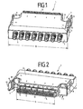
- Fig. 1
- ein Anschlussmodul in einer perspektivischen Rückansicht,
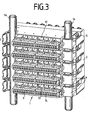
- Fig. 2
- das Anschlussmodul in einer perspektivischen Vorderansicht,
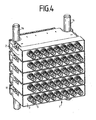
- Fig. 3
- mehrere Anschlussmodule in einer perspektivischen Vorderansicht in einem Montagegestell mit Rundstangen und
- Fig. 4
- eine perspektivische Rückansicht der Anschlussmodule.
- Das Anschlussmodul 1 umfasst ein Gehäuse 2 mit einer ersten Stirnseite 3 der Breite B und einer gegenüberliegenden Stirnseite 4 der Breite b, wobei gilt B > b. An der Stirnseite 3 sind acht Koaxial-Steckverbinder 5 angeordnet und an der Stirnseite 4 sechzehn Schneid-Klemm-Kontakte 6 zum Abschließen von acht Doppeladern. Die Schneid-Klemm-Kontakte 6 sind über eine im Gehäuse 2 angeordnete Leiterplatte mit den Koaxial-Steckverbindern 5 elektrisch über Filterbaugruppen zur Impedanzanpassung verbunden. Neben der Stirnseite 4 etwas zurückgesetzt sind zwei Befestigungselemente 7 angeordnet. Wie man in
Fig. 2 sieht, ist das linke Befestigungselement 7 in einer offenen Position und das rechte Befestigungselement 7 in einer geschlossenen Position dargestellt. Das Befestigungselement 7 ist zweiteilig ausgebildet, wobei ein erstes Befestigungsteil 8 bogenförmig ausgebildet ist und aus dem Gehäuse 2 ausgeformt ist. Im dargestellten Beispiel ist also das erste Befestigungsteil 8 ein Bestandteil des Gehäuses 2. Das zweite Befestigungsteil 9 ist an den äußeren Rändern des ersten Befestigungsteils 8 schwenkbar angelenkt. Das zweite Befestigungsteil 9 ist dabei mit mindestens einem Rastelement 10 ausgebildet, das an der anderen Seite des ersten Befestigungsteils 8 lösbar einrasten kann. Des Weiteren sind seitlich (ein- oder beidseitig) sowie auf der Oberseite des Gehäuses 2 Drahtführungen 11, 12 für die Doppeladern angeordnet. Ebenso sind an der die Schneid-Klemm-Kontakte 6 tragenden Anschlussleiste Drahtführungen 13 angeordnet. Ebenso ist es zum Anschließen von geschirmten Adern möglich, statt sechzehn vierundzwanzig bzw. fünfundzwanzig Schneid-Klemm-Kontakte 6 zu verwenden. Des Weiteren sei angemerkt, dass in das Befestigungsteil 8 ein Endkontakt zur Herstellung einer Masseverbindung angeordnet sein kann. - Anhand der
Fig. 3 und4 soll nun die Funktionsweise des Anschlussmoduls 1 näher erläutert werden. Wie man denFig. 3 und4 entnehmen kann, sind dabei jeweils fünf Anschlussmodule 1 auf zwei Rundstangen 14 als Teil eines Montagegestells dargestellt. Dabei ist die Stirnseite 3 mit Koaxial-Steckverbindem 5 meist die Systemseite und die Stirnseite 4 mit den Schneid-Klemm-Kontakten 6 die Rangierseite. Auf der Systemseite wird in Regelfall eine erfolgte Beschaltung kaum mehr geändert, wohingegen auf der Rangierseite häufiger die Verdrahtung geändert werden muss. Entsprechend wird ein Anschlussmodul 1 auf einem Montagegestell derart befestigt, dass die Rangierseite von der Vorderseite des Montagegestells zugänglich ist, an der im Regelfall mehr Platz für Rangierarbeiten ist. Im vorliegenden Beispiel werden also die Anschlussmodule 1 von der Rückseite des Montagegestells auf die Rundstangen 14 geschoben und anschließend durch Zuklappen und Verrasten der zweiten Befestigungsteile 9 auf den Rundstangen 14 verriegelt. Die Stärke der Verriegelung kann dabei entweder so gewählt werden, dass die Anschlussleiste auf den Rundstangen 14 fixiert ist oder aber derart gewählt werden, dass die Anschlussmodule 1 noch in Längsrichtung der Rundstangen 14 verschiebbar sind. Wie man am Besten inFig. 3 erkennen kann, würde ohne die zweiten Befestigungsteile 9 beim Anschalten von Adern an die Schneid-Klemm-Kontakte 6 die Gefahr bestehen, dass die Anschaltkräfte das Anschlussmodul 1 von den Rundstangen 14 drücken würden. -
- 1
- Anschlussmodul
- 2
- Gehäuse
- 3
- erste Stirnseite
- B
- Breite der ersten Stirnseite
- 4
- gegenüberliegende Stirnseite
- b
- Breite der gegenüberliegenden Stirnseite
- 5
- Koaxial-Steckverbinder
- 6
- Schneid-Klemm-Kontakte
- 7
- Befestigungselement
- 8
- Befestigungsteil
- 9
- Befestigungsteil
- 10
- Rastelement
- 11
- Drahtführung
- 12
- Drahtführung
- 13
- Drahtführung
- 14
- Rundstangen
Claims (12)
- Anschlussmodul (1) für die Telekommunikations- und Datentechnik, umfassend ein Gehäuse (2), elektrische Kontakte (5, 6) zum Anschließen von Adern und/oder Kabeln und mindestens ein Befestigungselement (7), wobei mittels des Befestigungselementes (7) das Anschlussmodul (1) an einem Montagegestell befestigt werden kann, das Befestigungselement (7) mindestens zweiteilig mit einem ersten Befestigungsteil (8) und einem zweiten Befestigungsteil (9) ausgebildet ist, wobei mittels des ersten Befestigungsteils (8) das Anschlussmodul (1) auf das Montagegestell aufsteckbar ist und mittels dessen zweiten Befestigungsteils (9) an dem Montagegestell verriegelbar ist, wobei das erste und zweite Befestigungsteil (8, 9) das Montagegestell vollständig im Umfang umfassen und das Befestigungselement (7) zum Befestigen an einer Rundstange (14) ausgebildet ist, wobei das erste Befestigungsteil (8) bogenförmig ausgebildet ist.
- Anschlussmodul nach Anspruch 1, dadurch gekennzeichnet, dass das zweite Befestigungsteil (9) am ersten Befestigungsteil (8) und/oder am Anschlussmodul (1) angelenkt ist.
- Anschlussmodul nach einem der vorangegangenen Ansprüche, dadurch gekennzeichnet, dass das zweite Befestigungsteil (9) an dem ersten Befestigungsteil (8) und/oder am Anschlussmodul (1) verrastbar ist.
- Anschlussmodul nach einem der vorangegangenen Ansprüche, dadurch gekennzeichnet, dass die Kontakte an gegenüberliegenden Stirnseiten (3, 4) des Gehäuses (2) angeordnet sind.
- Anschlussmodul nach Anspruch 4, dadurch gekennzeichnet, dass die gegenüberliegenden Stirnseiten (3, 4) eine unterschiedliche Breite (B, b) aufweisen, wobei das erste Befestigungsteil (8) seitlich an der schmaleren Stirnseite (4) angeordnet ist.
- Anschlussmodul nach einem der Ansprüche 4 oder 5, dadurch gekennzeichnet, dass die Kontakte der einen Stirnseite mindestens teilweise elektrisch mit den Kontakten der anderen Stirnseite verbunden sind.
- Anschlussmodul nach einem der vorangegangenen Ansprüche, dadurch gekennzeichnet, dass in dem Gehäuse (2) mindestens eine Leiterplatte angeordnet ist, wobei mindestens einzelne Kontakte über die Leiterplatte elektrisch verbunden sind.
- Anschlussmodul nach Anspruch 7, dadurch gekennzeichnet, dass auf der elektrischen Leiterplatte Filterbaugruppen, Schutzelemente und/oder Verstärkerschaltungen angeordnet sind.
- Anschlussmodul nach einem der vorangegangenen Ansprüche, dadurch gekennzeichnet, dass mindestens ein Teil der Kontakte als Schneid-Klemm-Kontakte (6) ausgebildet sind.
- Anschlussmodul nach einem der Ansprüche 5 bis 9, dadurch gekennzeichnet, dass die Kontakte auf der schmaleren Stirnseite (4) als Schneid-Klemm-Kontakte (6) ausgebildet sind.
- Anschlussmodul nach einem der Ansprüche 5 bis 10, dadurch gekennzeichnet, dass die Kontakte auf der breiteren Stirnseite (3) als Koaxial-Steckverbinder (5) ausgebildet sind.
- Anschlussmodul nach einem der vorangegangenen Ansprüche, dadurch gekennzeichnet, dass das Anschlussmodul (1) zusätzlich mit Trennkontakten ausgebildet ist, mittels derer die elektrische Verbindung zwischen zwei Kontakten auftrennbar ist.
Priority Applications (2)
| Application Number | Priority Date | Filing Date | Title |
|---|---|---|---|
| SI200530739T SI1787481T1 (sl) | 2004-09-10 | 2005-08-30 | Priključni modul za telekomunikacijsko in podatkovno tehnologijo |
| PL05776552T PL1787481T3 (pl) | 2004-09-10 | 2005-08-30 | Moduł przyłączowy dla telekomunikacji i przetwarzania danych |
Applications Claiming Priority (2)
| Application Number | Priority Date | Filing Date | Title |
|---|---|---|---|
| DE102004043764A DE102004043764B3 (de) | 2004-09-10 | 2004-09-10 | Anschlussmodul für die Telekommunikations- und Datentechnik |
| PCT/EP2005/009317 WO2006027143A1 (de) | 2004-09-10 | 2005-08-30 | Anschlussmodul für die telekommunikations- und datentechnik |
Publications (2)
| Publication Number | Publication Date |
|---|---|
| EP1787481A1 EP1787481A1 (de) | 2007-05-23 |
| EP1787481B1 true EP1787481B1 (de) | 2009-05-27 |
Family
ID=35044935
Family Applications (1)
| Application Number | Title | Priority Date | Filing Date |
|---|---|---|---|
| EP05776552A Expired - Lifetime EP1787481B1 (de) | 2004-09-10 | 2005-08-30 | Anschlussmodul für die telekommunikations- und datentechnik |
Country Status (17)
| Country | Link |
|---|---|
| US (2) | US7710733B2 (de) |
| EP (1) | EP1787481B1 (de) |
| KR (1) | KR100901100B1 (de) |
| CN (1) | CN101010966A (de) |
| AT (1) | ATE432593T1 (de) |
| AU (1) | AU2005281942B9 (de) |
| BR (1) | BRPI0515152A (de) |
| DE (2) | DE102004043764B3 (de) |
| EG (1) | EG25343A (de) |
| MX (1) | MX2007001588A (de) |
| PL (1) | PL1787481T3 (de) |
| PT (1) | PT1787481E (de) |
| RS (1) | RS50974B (de) |
| SI (1) | SI1787481T1 (de) |
| TW (1) | TWI351145B (de) |
| WO (1) | WO2006027143A1 (de) |
| ZA (1) | ZA200701988B (de) |
Families Citing this family (15)
| Publication number | Priority date | Publication date | Assignee | Title |
|---|---|---|---|---|
| DE102004043764B3 (de) * | 2004-09-10 | 2006-02-02 | Adc Gmbh | Anschlussmodul für die Telekommunikations- und Datentechnik |
| DE102007032578A1 (de) * | 2007-07-09 | 2009-01-15 | Adc Gmbh | Anschlussmodul für die Telekommunikations- und Datentechnik |
| DE102007032577B4 (de) | 2007-07-09 | 2011-07-21 | ADC GmbH, 14167 | Endverschluss für die Telekommunikations- und Datentechnik |
| DE102007032579B4 (de) * | 2007-07-09 | 2017-05-04 | Tyco Electronics Services Gmbh | Endverschluss für die Telekommunikations- und Datentechnik |
| US7771229B2 (en) * | 2008-02-04 | 2010-08-10 | Hon Hai Precision Ind. Co., Ltd. | Electrical card connector assembly |
| DE102008033430B4 (de) * | 2008-07-16 | 2010-04-01 | Adc Gmbh | Verteileranschlussmodul für die Telekommunikations- und Datentechnik |
| DE102011105362A1 (de) * | 2011-06-22 | 2012-12-27 | Tyco Electronics Services Gmbh | Befestigungsvorrichtung einer Aufnahme für Telekommunikationseinrichtungen und Aufnahme |
| EP2566181A1 (de) * | 2011-08-31 | 2013-03-06 | 3M Innovative Properties Company | Funktionsmodul für eine Telekommunikationsleitung für ein Telekommunikationssystem |
| USD700896S1 (en) * | 2012-01-27 | 2014-03-11 | Mitsubishi Electric Corporation | Heat medium relay unit |
| USD700581S1 (en) * | 2012-04-11 | 2014-03-04 | Mitsubishi Electric Corporation | Heat medium relay unit |
| JP6082608B2 (ja) * | 2013-01-30 | 2017-02-15 | 株式会社ディーアンドエムホールディングス | 端子用取付けベース、スピーカ端子、およびオーディオ機器 |
| US10801540B2 (en) | 2015-04-17 | 2020-10-13 | Enduralock, Llc | Locking mechanisms with deflectable lock member |
| US9595798B2 (en) * | 2015-06-17 | 2017-03-14 | The Boeing Company | VME P2 five row interface adapter assembly, system, and method |
| DE102016102098B4 (de) * | 2016-02-05 | 2022-01-27 | Cobinet Fernmelde- Und Datennetzkomponenten Gmbh | Verbindungsmodul für die Telekommunikations- und Datentechnik |
| US10259229B2 (en) * | 2016-10-25 | 2019-04-16 | Seiko Epson Corporation | Ink container and printer |
Family Cites Families (13)
| Publication number | Priority date | Publication date | Assignee | Title |
|---|---|---|---|---|
| EP0300065B1 (de) * | 1987-07-18 | 1992-09-02 | Weidmüller Interface GmbH & Co. | Montagefuss zum Befestigen von elektrisch/elektronischen Bauelementen auf Tragschienen |
| DE3728368C1 (de) * | 1987-08-21 | 1988-11-10 | Krone Ag | Vorrichtung zur Halterung von Anschlussleisten der Fernmeldetechnik |
| US5127851A (en) * | 1991-07-25 | 1992-07-07 | Reliance Comm/Tec Corporation | Modular patch panel |
| US6049709A (en) | 1996-12-06 | 2000-04-11 | Adc Telecommunications, Inc. | RF circuit module |
| CN2300543Y (zh) | 1997-09-10 | 1998-12-16 | 陈建中 | 扣盖式汽车油箱电自动开闭锁装置 |
| DE19803420A1 (de) | 1998-01-29 | 1999-08-12 | Quante Ag | Modul der Telekommunikationstechnik |
| DE10029649C9 (de) * | 2000-06-15 | 2008-02-07 | Adc Gmbh | Verteileranschlußmodul für die Telekommunikations- und Datentechnik |
| KR100426483B1 (ko) | 2001-12-22 | 2004-04-14 | 주식회사 하이닉스반도체 | 플래쉬 메모리 셀의 제조 방법 |
| DE10236361C5 (de) | 2002-08-08 | 2010-08-12 | Adc Gmbh | Verteileranschlußmodul für die Telekommunikations- und Datentechnik |
| KR200353314Y1 (ko) | 2004-03-16 | 2004-06-14 | 전영찬 | 아이디씨 텔레콤 블록 지지장치 |
| DE102004043764B3 (de) * | 2004-09-10 | 2006-02-02 | Adc Gmbh | Anschlussmodul für die Telekommunikations- und Datentechnik |
| DE102004043763B3 (de) * | 2004-09-10 | 2006-02-02 | Adc Gmbh | Verteilermodul zur Umsetzung zwischen symmetrischen und unsymmetrischen Datenübertragungsstrecken |
| US20070082522A1 (en) * | 2005-10-11 | 2007-04-12 | Pierre Bonvallat | Carrier and an assembly including a carrier and a telecommunications module |
-
2004
- 2004-09-10 DE DE102004043764A patent/DE102004043764B3/de not_active Expired - Fee Related
-
2005
- 2005-08-30 MX MX2007001588A patent/MX2007001588A/es active IP Right Grant
- 2005-08-30 EP EP05776552A patent/EP1787481B1/de not_active Expired - Lifetime
- 2005-08-30 PT PT05776552T patent/PT1787481E/pt unknown
- 2005-08-30 KR KR1020077005296A patent/KR100901100B1/ko not_active Expired - Fee Related
- 2005-08-30 AU AU2005281942A patent/AU2005281942B9/en not_active Ceased
- 2005-08-30 PL PL05776552T patent/PL1787481T3/pl unknown
- 2005-08-30 DE DE502005007363T patent/DE502005007363D1/de not_active Expired - Lifetime
- 2005-08-30 BR BRPI0515152-0A patent/BRPI0515152A/pt not_active IP Right Cessation
- 2005-08-30 SI SI200530739T patent/SI1787481T1/sl unknown
- 2005-08-30 US US11/661,657 patent/US7710733B2/en not_active Expired - Fee Related
- 2005-08-30 CN CNA2005800296565A patent/CN101010966A/zh active Pending
- 2005-08-30 WO PCT/EP2005/009317 patent/WO2006027143A1/de not_active Ceased
- 2005-08-30 RS RSP-2009/0305A patent/RS50974B/sr unknown
- 2005-08-30 AT AT05776552T patent/ATE432593T1/de active
- 2005-09-09 TW TW094131156A patent/TWI351145B/zh not_active IP Right Cessation
-
2007
- 2007-03-07 EG EGNA2007000252 patent/EG25343A/xx active
- 2007-03-07 ZA ZA200701988A patent/ZA200701988B/xx unknown
-
2010
- 2010-04-06 US US12/755,187 patent/US7894196B2/en not_active Expired - Fee Related
Also Published As
| Publication number | Publication date |
|---|---|
| ZA200701988B (en) | 2008-08-27 |
| SI1787481T1 (sl) | 2009-10-31 |
| US7894196B2 (en) | 2011-02-22 |
| BRPI0515152A (pt) | 2008-07-08 |
| AU2005281942A1 (en) | 2006-03-16 |
| TWI351145B (en) | 2011-10-21 |
| EG25343A (en) | 2011-12-14 |
| PT1787481E (pt) | 2009-07-07 |
| RS50974B (sr) | 2010-10-31 |
| US20100190374A1 (en) | 2010-07-29 |
| MX2007001588A (es) | 2007-04-02 |
| TW200623547A (en) | 2006-07-01 |
| DE502005007363D1 (de) | 2009-07-09 |
| ATE432593T1 (de) | 2009-06-15 |
| KR20070050948A (ko) | 2007-05-16 |
| DE102004043764B3 (de) | 2006-02-02 |
| US20090029588A1 (en) | 2009-01-29 |
| KR100901100B1 (ko) | 2009-06-08 |
| PL1787481T3 (pl) | 2009-09-30 |
| US7710733B2 (en) | 2010-05-04 |
| AU2005281942B2 (en) | 2010-02-25 |
| WO2006027143A1 (de) | 2006-03-16 |
| EP1787481A1 (de) | 2007-05-23 |
| CN101010966A (zh) | 2007-08-01 |
| AU2005281942B9 (en) | 2010-08-05 |
Similar Documents
| Publication | Publication Date | Title |
|---|---|---|
| EP1658660B1 (de) | Verteileranschlussmodul | |
| DE10341694B3 (de) | Anschlussmodul | |
| DE102004043764B3 (de) | Anschlussmodul für die Telekommunikations- und Datentechnik | |
| EP2862364B1 (de) | Verteileranschlussmodul | |
| DE69431895T2 (de) | Teilnehmerschnittstelledose | |
| EP2057719A2 (de) | Adapter und steckverbindungssystem | |
| EP0446572A1 (de) | Anschlussleiste für die Fernmelde- und Datentechnik | |
| DE8800759U1 (de) | Elektrischer Verbinder mit beweglichem Führungselement | |
| DE102007026096A1 (de) | Aderanschlussmodul | |
| EP3021421A1 (de) | Anschlussvorrichtung für mehrleiterkabel | |
| EP1829387B1 (de) | Kabelsteckverbinder für leiterplatten | |
| EP1744404B2 (de) | Anschlussvorrichtung und Anschlusssystem für isolierte elektrische Leiter | |
| WO2008086865A1 (de) | Elektrischer steckverbinder | |
| EP1905127B1 (de) | Schneidklemm-steckverbinder und einrichtung für die telekommunikations- und datentechnik | |
| DE102007026102B3 (de) | Steckverbinder für Leiterplatten | |
| EP0952635B1 (de) | Elektrischer Verbinder | |
| DE3879365T2 (de) | Klinkensteckermodul mit eingebauten lampen. | |
| DE10001553A1 (de) | Vorrichtung zur Schirmung für Anschlussleisten | |
| EP1753090B1 (de) | Elektrische Steckvorrichtung bzw. Steckverbindung | |
| EP2441128B1 (de) | Anschlussleiste | |
| EP1782504B1 (de) | Steckbare überspannungsschutz-anordnung | |
| DE3806049C2 (de) | ||
| EP1472766A1 (de) | Anschluss- oder verteilvorrichtung für elektrische installationsgeräte | |
| EP0660458B1 (de) | Anschlusseinheit für Telekommunikations- und Datenleitungen | |
| EP1109256B1 (de) | Anschlusselement zum Anschliessen von Kabelschirmen |
Legal Events
| Date | Code | Title | Description |
|---|---|---|---|
| PUAI | Public reference made under article 153(3) epc to a published international application that has entered the european phase |
Free format text: ORIGINAL CODE: 0009012 |
|
| 17P | Request for examination filed |
Effective date: 20061214 |
|
| AK | Designated contracting states |
Kind code of ref document: A1 Designated state(s): AT BE BG CH CY CZ DE DK EE ES FI FR GB GR HU IE IS IT LI LT LU LV MC NL PL PT RO SE SI SK TR |
|
| AX | Request for extension of the european patent |
Extension state: AL BA HR MK YU |
|
| 17Q | First examination report despatched |
Effective date: 20070718 |
|
| GRAP | Despatch of communication of intention to grant a patent |
Free format text: ORIGINAL CODE: EPIDOSNIGR1 |
|
| GRAS | Grant fee paid |
Free format text: ORIGINAL CODE: EPIDOSNIGR3 |
|
| GRAA | (expected) grant |
Free format text: ORIGINAL CODE: 0009210 |
|
| AK | Designated contracting states |
Kind code of ref document: B1 Designated state(s): AT BE BG CH CY CZ DE DK EE ES FI FR GB GR HU IE IS IT LI LT LU LV MC NL PL PT RO SE SI SK TR |
|
| AX | Request for extension of the european patent |
Extension state: AL BA HR MK YU |
|
| REG | Reference to a national code |
Ref country code: GB Ref legal event code: FG4D Free format text: NOT ENGLISH |
|
| REG | Reference to a national code |
Ref country code: CH Ref legal event code: EP Ref country code: CH Ref legal event code: NV Representative=s name: MICHELI & CIE SA |
|
| REG | Reference to a national code |
Ref country code: IE Ref legal event code: FG4D Free format text: LANGUAGE OF EP DOCUMENT: GERMAN |
|
| REG | Reference to a national code |
Ref country code: PT Ref legal event code: SC4A Free format text: AVAILABILITY OF NATIONAL TRANSLATION Effective date: 20090630 |
|
| REF | Corresponds to: |
Ref document number: 502005007363 Country of ref document: DE Date of ref document: 20090709 Kind code of ref document: P |
|
| REG | Reference to a national code |
Ref country code: GR Ref legal event code: EP Ref document number: 20090402005 Country of ref document: GR |
|
| REG | Reference to a national code |
Ref country code: PL Ref legal event code: T3 |
|
| PG25 | Lapsed in a contracting state [announced via postgrant information from national office to epo] |
Ref country code: LT Free format text: LAPSE BECAUSE OF FAILURE TO SUBMIT A TRANSLATION OF THE DESCRIPTION OR TO PAY THE FEE WITHIN THE PRESCRIBED TIME-LIMIT Effective date: 20090527 |
|
| NLV1 | Nl: lapsed or annulled due to failure to fulfill the requirements of art. 29p and 29m of the patents act | ||
| PG25 | Lapsed in a contracting state [announced via postgrant information from national office to epo] |
Ref country code: LV Free format text: LAPSE BECAUSE OF FAILURE TO SUBMIT A TRANSLATION OF THE DESCRIPTION OR TO PAY THE FEE WITHIN THE PRESCRIBED TIME-LIMIT Effective date: 20090527 Ref country code: SE Free format text: LAPSE BECAUSE OF FAILURE TO SUBMIT A TRANSLATION OF THE DESCRIPTION OR TO PAY THE FEE WITHIN THE PRESCRIBED TIME-LIMIT Effective date: 20090827 Ref country code: NL Free format text: LAPSE BECAUSE OF FAILURE TO SUBMIT A TRANSLATION OF THE DESCRIPTION OR TO PAY THE FEE WITHIN THE PRESCRIBED TIME-LIMIT Effective date: 20090527 Ref country code: IS Free format text: LAPSE BECAUSE OF FAILURE TO SUBMIT A TRANSLATION OF THE DESCRIPTION OR TO PAY THE FEE WITHIN THE PRESCRIBED TIME-LIMIT Effective date: 20090927 |
|
| REG | Reference to a national code |
Ref country code: IE Ref legal event code: FD4D |
|
| PG25 | Lapsed in a contracting state [announced via postgrant information from national office to epo] |
Ref country code: RO Free format text: LAPSE BECAUSE OF FAILURE TO SUBMIT A TRANSLATION OF THE DESCRIPTION OR TO PAY THE FEE WITHIN THE PRESCRIBED TIME-LIMIT Effective date: 20090527 Ref country code: DK Free format text: LAPSE BECAUSE OF FAILURE TO SUBMIT A TRANSLATION OF THE DESCRIPTION OR TO PAY THE FEE WITHIN THE PRESCRIBED TIME-LIMIT Effective date: 20090527 Ref country code: IE Free format text: LAPSE BECAUSE OF FAILURE TO SUBMIT A TRANSLATION OF THE DESCRIPTION OR TO PAY THE FEE WITHIN THE PRESCRIBED TIME-LIMIT Effective date: 20090527 Ref country code: ES Free format text: LAPSE BECAUSE OF FAILURE TO SUBMIT A TRANSLATION OF THE DESCRIPTION OR TO PAY THE FEE WITHIN THE PRESCRIBED TIME-LIMIT Effective date: 20090907 Ref country code: EE Free format text: LAPSE BECAUSE OF FAILURE TO SUBMIT A TRANSLATION OF THE DESCRIPTION OR TO PAY THE FEE WITHIN THE PRESCRIBED TIME-LIMIT Effective date: 20090527 |
|
| PG25 | Lapsed in a contracting state [announced via postgrant information from national office to epo] |
Ref country code: SK Free format text: LAPSE BECAUSE OF FAILURE TO SUBMIT A TRANSLATION OF THE DESCRIPTION OR TO PAY THE FEE WITHIN THE PRESCRIBED TIME-LIMIT Effective date: 20090527 |
|
| BERE | Be: lapsed |
Owner name: ADC G.M.B.H. Effective date: 20090831 |
|
| PG25 | Lapsed in a contracting state [announced via postgrant information from national office to epo] |
Ref country code: BG Free format text: LAPSE BECAUSE OF FAILURE TO SUBMIT A TRANSLATION OF THE DESCRIPTION OR TO PAY THE FEE WITHIN THE PRESCRIBED TIME-LIMIT Effective date: 20090827 Ref country code: MC Free format text: LAPSE BECAUSE OF NON-PAYMENT OF DUE FEES Effective date: 20090831 |
|
| PLBE | No opposition filed within time limit |
Free format text: ORIGINAL CODE: 0009261 |
|
| STAA | Information on the status of an ep patent application or granted ep patent |
Free format text: STATUS: NO OPPOSITION FILED WITHIN TIME LIMIT |
|
| 26N | No opposition filed |
Effective date: 20100302 |
|
| PG25 | Lapsed in a contracting state [announced via postgrant information from national office to epo] |
Ref country code: BE Free format text: LAPSE BECAUSE OF NON-PAYMENT OF DUE FEES Effective date: 20090831 |
|
| PG25 | Lapsed in a contracting state [announced via postgrant information from national office to epo] |
Ref country code: LU Free format text: LAPSE BECAUSE OF NON-PAYMENT OF DUE FEES Effective date: 20090830 |
|
| PG25 | Lapsed in a contracting state [announced via postgrant information from national office to epo] |
Ref country code: HU Free format text: LAPSE BECAUSE OF FAILURE TO SUBMIT A TRANSLATION OF THE DESCRIPTION OR TO PAY THE FEE WITHIN THE PRESCRIBED TIME-LIMIT Effective date: 20091128 |
|
| PG25 | Lapsed in a contracting state [announced via postgrant information from national office to epo] |
Ref country code: CY Free format text: LAPSE BECAUSE OF FAILURE TO SUBMIT A TRANSLATION OF THE DESCRIPTION OR TO PAY THE FEE WITHIN THE PRESCRIBED TIME-LIMIT Effective date: 20090527 |
|
| PGFP | Annual fee paid to national office [announced via postgrant information from national office to epo] |
Ref country code: CH Payment date: 20110824 Year of fee payment: 7 |
|
| PGFP | Annual fee paid to national office [announced via postgrant information from national office to epo] |
Ref country code: FI Payment date: 20110822 Year of fee payment: 7 Ref country code: DE Payment date: 20110831 Year of fee payment: 7 Ref country code: AT Payment date: 20110822 Year of fee payment: 7 Ref country code: CZ Payment date: 20110822 Year of fee payment: 7 Ref country code: TR Payment date: 20110818 Year of fee payment: 7 Ref country code: GB Payment date: 20110824 Year of fee payment: 7 Ref country code: GR Payment date: 20110823 Year of fee payment: 7 Ref country code: PL Payment date: 20110817 Year of fee payment: 7 Ref country code: FR Payment date: 20110829 Year of fee payment: 7 Ref country code: PT Payment date: 20110818 Year of fee payment: 7 Ref country code: SI Payment date: 20110817 Year of fee payment: 7 |
|
| PGFP | Annual fee paid to national office [announced via postgrant information from national office to epo] |
Ref country code: IT Payment date: 20110825 Year of fee payment: 7 |
|
| REG | Reference to a national code |
Ref country code: PT Ref legal event code: MM4A Free format text: LAPSE DUE TO NON-PAYMENT OF FEES Effective date: 20130228 |
|
| REG | Reference to a national code |
Ref country code: CH Ref legal event code: PL |
|
| REG | Reference to a national code |
Ref country code: AT Ref legal event code: MM01 Ref document number: 432593 Country of ref document: AT Kind code of ref document: T Effective date: 20120830 |
|
| GBPC | Gb: european patent ceased through non-payment of renewal fee |
Effective date: 20120830 |
|
| PG25 | Lapsed in a contracting state [announced via postgrant information from national office to epo] |
Ref country code: CZ Free format text: LAPSE BECAUSE OF NON-PAYMENT OF DUE FEES Effective date: 20120830 Ref country code: CH Free format text: LAPSE BECAUSE OF NON-PAYMENT OF DUE FEES Effective date: 20120831 Ref country code: FI Free format text: LAPSE BECAUSE OF NON-PAYMENT OF DUE FEES Effective date: 20120830 Ref country code: LI Free format text: LAPSE BECAUSE OF NON-PAYMENT OF DUE FEES Effective date: 20120831 |
|
| REG | Reference to a national code |
Ref country code: GR Ref legal event code: ML Ref document number: 20090402005 Country of ref document: GR Effective date: 20130304 |
|
| REG | Reference to a national code |
Ref country code: FR Ref legal event code: ST Effective date: 20130430 |
|
| PG25 | Lapsed in a contracting state [announced via postgrant information from national office to epo] |
Ref country code: GR Free format text: LAPSE BECAUSE OF NON-PAYMENT OF DUE FEES Effective date: 20130304 Ref country code: IT Free format text: LAPSE BECAUSE OF NON-PAYMENT OF DUE FEES Effective date: 20120830 Ref country code: PT Free format text: LAPSE BECAUSE OF NON-PAYMENT OF DUE FEES Effective date: 20130228 Ref country code: SI Free format text: LAPSE BECAUSE OF NON-PAYMENT OF DUE FEES Effective date: 20120831 |
|
| REG | Reference to a national code |
Ref country code: SI Ref legal event code: KO00 Effective date: 20130404 |
|
| PG25 | Lapsed in a contracting state [announced via postgrant information from national office to epo] |
Ref country code: AT Free format text: LAPSE BECAUSE OF NON-PAYMENT OF DUE FEES Effective date: 20120830 |
|
| PG25 | Lapsed in a contracting state [announced via postgrant information from national office to epo] |
Ref country code: GB Free format text: LAPSE BECAUSE OF NON-PAYMENT OF DUE FEES Effective date: 20120830 Ref country code: DE Free format text: LAPSE BECAUSE OF NON-PAYMENT OF DUE FEES Effective date: 20130301 |
|
| PG25 | Lapsed in a contracting state [announced via postgrant information from national office to epo] |
Ref country code: FR Free format text: LAPSE BECAUSE OF NON-PAYMENT OF DUE FEES Effective date: 20120831 |
|
| REG | Reference to a national code |
Ref country code: DE Ref legal event code: R119 Ref document number: 502005007363 Country of ref document: DE Effective date: 20130301 |
|
| PG25 | Lapsed in a contracting state [announced via postgrant information from national office to epo] |
Ref country code: PL Free format text: LAPSE BECAUSE OF NON-PAYMENT OF DUE FEES Effective date: 20120830 |
|
| REG | Reference to a national code |
Ref country code: PL Ref legal event code: LAPE |
|
| PG25 | Lapsed in a contracting state [announced via postgrant information from national office to epo] |
Ref country code: TR Free format text: LAPSE BECAUSE OF NON-PAYMENT OF DUE FEES Effective date: 20120830 |