EP1785693B1 - Optical edge break gage - Google Patents
Optical edge break gage Download PDFInfo
- Publication number
- EP1785693B1 EP1785693B1 EP06255799A EP06255799A EP1785693B1 EP 1785693 B1 EP1785693 B1 EP 1785693B1 EP 06255799 A EP06255799 A EP 06255799A EP 06255799 A EP06255799 A EP 06255799A EP 1785693 B1 EP1785693 B1 EP 1785693B1
- Authority
- EP
- European Patent Office
- Prior art keywords
- projection
- light
- light path
- viewing
- image
- Prior art date
- Legal status (The legal status is an assumption and is not a legal conclusion. Google has not performed a legal analysis and makes no representation as to the accuracy of the status listed.)
- Not-in-force
Links
Images

Classifications
-
- G—PHYSICS
- G01—MEASURING; TESTING
- G01B—MEASURING LENGTH, THICKNESS OR SIMILAR LINEAR DIMENSIONS; MEASURING ANGLES; MEASURING AREAS; MEASURING IRREGULARITIES OF SURFACES OR CONTOURS
- G01B11/00—Measuring arrangements characterised by the use of optical techniques
- G01B11/24—Measuring arrangements characterised by the use of optical techniques for measuring contours or curvatures
- G01B11/25—Measuring arrangements characterised by the use of optical techniques for measuring contours or curvatures by projecting a pattern, e.g. one or more lines, moiré fringes on the object
- G01B11/2513—Measuring arrangements characterised by the use of optical techniques for measuring contours or curvatures by projecting a pattern, e.g. one or more lines, moiré fringes on the object with several lines being projected in more than one direction, e.g. grids, patterns
Definitions
- This invention is generally related to the field of optical-based measurements, and, more particularly, relates to the use of fringe patterns optically projected onto a surface to obtain three-dimensional (3-D) measurements, as may be used for profiling an edge break in a manufactured part.
- Machined parts for various applications may have edges shaped for achieving specified mechanical properties, including avoidance or reduction of stress concentrations.
- edges shaped for achieving specified mechanical properties including avoidance or reduction of stress concentrations.
- Features and/or geometric discontinuities that could give rise to edge sharpness, such as may be encountered in a chamfer, bevel, fillet and other part features will be referred to in the context of this description as an edge break.
- edge breaks have been measured using a wax or soft-metal impression of the edge. The impression is then measured using a stylus or a tracer-type of mechanical gage, or is sectioned on planes normal to the line of the edge, and viewed using an optical comparator. This practice is generally time consuming and inexact due to challenges in making an accurate replica of the edge break, and obtaining a correct cross sectional mapping.
- JP-A-2000 097 672 describes an optical gage for 3D surface profile measuring, comprising:
- EP-A-1 482 275 describes an optical edge gage for 3D surface profile measuring, comprising:
- an optical edge break gage for 3D surface profile measuring comprising:
- FIG. 1 shows a schematic view of a hand-held projector 20 and attached viewer 50.
- the projector has a light source 22, such as a light-emitting diode (LED), with a power source 24, such as a battery or a cord connection to an electrical outlet.
- the projector 20 comprises an optics system that may include a condenser lens 28 with a condenser aperture 30, and an imaging lens 42 with an imaging aperture 40.
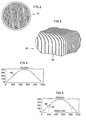
- a grating 34 of alternating opaque and transparent areas is mounted at or near the focal plane of the imaging lens. A Ronchi ruling may be used as illustrated in FIG 2 .
- the grating 34 projects a structured light pattern 46 onto a surface 80 as illustrated in FIG 3 .
- the light source 22 produces diverging rays 26, which are collected and directed by the condensing lens 28 into collected rays 32. These rays pass through the grating 34, which blocks parts of the beam, resulting in a structured light pattern 46.
- a Ronchi grating is used, this results in a projection of planar beams.
- Light intensity varies on a line normal to these beams as a square waveform with a fundamental sinusoidal component 36 and harmonic components 38 that define the sharp changes in intensity in the square wave.
- the harmonic components 38 are diffracted by the grating to angles that increase with frequency, and can therefore be removed by the imaging aperture 40. This removes extraneous interference patterns that would otherwise appear on the surface 80 due to crossing harmonics.
- the imaging aperture 40 may comprise for example a slit parallel to the Ronchi lines.
- a viewer 50 is attached to the projector 20, in this example via a bracket 64, and comprises optics 52 with an optical axis 54 that is non-parallel to the projector optical axis 44.
- a digital camera element 57 in the viewing system 50 may comprise an image sensor 58, such as a charge-coupled device array, an analog-to-digital converter 59, and other electronics as will be known by those skilled in the field of digital cameras. These elements digitize an image of the diffuse reflection 46 of the structured light pattern from the surface 80 as viewed along the viewing light path 56.
- the camera electronics may be connected to an internal battery and memory for storing data for later processing (not shown), or they may be connected to an external computer 61 by wired or wireless means via an interface circuit 60 such as a universal serial bus interface as known in the field of computer input devices.
- the computer interface circuit may be included in the camera electronics as is known in the field of digital cameras.
- one or more hand grips 66 may be attached to any desired area of the projector and/or viewer for hand-held operation.
- a trigger button 68 may be provided to trigger a snapshot as known in the field of digital cameras. Acquisition of a digital snapshot may take just a few milliseconds, so substantial steadiness over a relatively long period of time is not required.
- the gage assembly may be attached to a robotic arm, for automatic operation as known in the field of robotic assembly and inspection.
- a guide tip 70 may extend forward of the viewing system 50 beside or around the light paths 44, 54 to steady and position the break gage unit at a distance from the surface 80 such that the surface is sufficiently proximate the intersection of the optical axes 44, 54 and within a common field of view of the projector and viewer.
- the viewer optics 52 may be designed with a field of view optimized for looking around an edge of 90 degrees or more.
- An example of suitable viewer optical specifications for edge break analysis of a turbine component may be as follows:
- either or both the projector and the viewer optics could include a telecentric lens system or other optical system configured to improve the uniformity of the light or image field and/or to improve the optical access to the edge surfaces.
- a telecentric lens system makes all views to the surface substantially parallel. In the case of the viewer, this would provide a more uniform collection of light from the two sides of the edge break.
- An example of an optical system configured to improve the uniformity of the light may include a mirror system arranged to direct the illumination to the two sides of the edge more uniformly.
- An edge being profiled may be oriented at an angle that is essentially normal to the viewing system optical axis and away from the specular reflection from the illumination system, so as to view the diffusely reflected light without interference from any specularly reflected light.
- the exact orientation of the angle of view is non-critical to the operation of the device.
- the grating 34 is positioned at an angle to the projection optical axis 44 to provide a focal plane of the grating image that crosses the surface 80 at an average depth on the area being profiled, taking the above surface orientation into account.
- the edge being profiled may be preferably oriented such that lines of the light pattern cross the edge, rather than follow it. However, the pattern contours need not be normal to an edge line for satisfactory operation.
- Moire interferometry can be used with this system with the addition of a sub-grating (not shown) in the viewing system 50.
- a sub-grating not shown
- the computer 61 may implement various known analysis methods or processing techniques, such as phase shift analysis.
- phase shift analysis uses the combination of three or more images of a periodic pattern, each with a small displacement or phase shift of the pattern to calculate the effective phase of the pattern at each point in the image, then further uses this information to calculate the overall shape of the part surface.
- phase shift analysis can be performed on a single image by means of a bias fringe pattern that can then be mathematically shifted to perform the same analysis.
- Additional exemplary analysis or processing techniques include Fourier profilometry, a mathematical analysis method for measuring surface profiles using distortions in periodic patterns projected onto a surface.
- Fourier profilometry can be used to mathematically model the surface based on contour information provided by the digitized structured light image.
- the method uses Fourier analysis with a two-dimensional fast Fourier transform to determine localized slopes on a curving surface. This allows an x, y, z coordinate system of the surface to be generated from a single image that has been overlaid with the distortion pattern.
- triangulation is a measuring method in which the distance to an object is calculated based upon angular relationships.
- Optical triangulation is used to associate distance or range information with each point on a 2D image of a surface being measured, providing the third dimension, or z coordinate. To calculate the distance information, a measure of a change in a structured light pattern projected onto the surface is analyzed relative to the same pattern in some reference state.
- Optical triangulation methods use a beam of light striking a surface at some angle to the surface. As the distance to the surface is changed, a given reflected spot of this light will move to a different location on the surface. This effect assumes that the surface is viewed at some angle other than the incident angle of the beam. Projecting a planar beam illuminates a line on the surface instead of a spot, creating a continuous series of illuminated points that trace the surface as though the part has been cut by the planar beam. Thus a planar beam of light will produce a contour of the surface as seen from a viewer's perspective outside the plane of the planar beam.
- a generated mathematical model can then produce profiles of surface sections normal to the line of an edge for comparison to part specifications for inspecting manufactured parts.
- a profile along any section of interest can be provided at any angle from the mathematical model as known in the field of 3D computer aided design (CAD) programs.
- CAD computer aided design
- Such profiles can be displayed on a computer display 62 as illustrated in FIGs 4 and 5 , and/or automatically analyzed for conformance to specifications.
- a radius of curvature 49 can be computed from a modeled fillet profile 48 by known arc fitting formulas, and be displayed as illustrated in FIG 5 , and/or the specified radius of curvature can be displayed textually or graphically on the profile for comparison.
- An enlarged 3D wire frame view of the modeled surface may be displayed for visual confirmation of generally correct modeling.
- aspects of the present invention can also be embodied as computer readable code on a computer readable medium.
- the computer readable medium may be any data storage device that can store data, which thereafter can be read by a computer system. Examples of computer readable medium include read-only memory, random-access memory, CD-ROMs, DVDs, magnetic tape, optical data storage devices.
- the computer readable medium can also be distributed over network coupled computer systems so that the computer readable code is stored and executed in a distributed fashion.
- aspects of the present invention may be implemented using computer programming or engineering techniques including computer software, firmware, hardware or any combination or subset thereof.
- Any such resulting program, having computer-readable code means may be embodied or provided within one or more computer-readable media, thereby making a computer program product, i.e., an article of manufacture, according to the invention.
- the computer readable media may be, for example, a fixed (hard) drive, diskette, optical disk, magnetic tape, semiconductor memory such as read-only memory (ROM), etc., or any transmitting/receiving medium such as the Internet or other communication network or link.
- the article of manufacture containing the computer code may be made and/or used by executing the code directly from one medium, by copying the code from one medium to another medium, or by transmitting the code over a network.
- An apparatus for making, using or selling the invention may be one or more processing systems including, but not limited to, a central processing unit (CPU), memory, storage devices, communication links and devices, servers, I/O devices, or any sub-components of one or more processing systems, including software, firmware, hardware or any combination or subset thereof, which embody the invention as set forth in the claims.
- CPU central processing unit
- memory storage devices
- communication links and devices servers
- I/O devices I/O devices
- any sub-components of one or more processing systems including software, firmware, hardware or any combination or subset thereof, which embody the invention as set forth in the claims.
- User input may be received from the keyboard, mouse, pen, voice, touch screen, or any other means by which a human can input data to a computer, including through other programs such as application programs.
Landscapes
- Engineering & Computer Science (AREA)
- Computer Vision & Pattern Recognition (AREA)
- Physics & Mathematics (AREA)
- General Physics & Mathematics (AREA)
- Length Measuring Devices By Optical Means (AREA)
Applications Claiming Priority (1)
| Application Number | Priority Date | Filing Date | Title |
|---|---|---|---|
| US11/274,578 US7489408B2 (en) | 2005-11-15 | 2005-11-15 | Optical edge break gage |
Publications (2)
| Publication Number | Publication Date |
|---|---|
| EP1785693A1 EP1785693A1 (en) | 2007-05-16 |
| EP1785693B1 true EP1785693B1 (en) | 2009-01-28 |
Family
ID=37680699
Family Applications (1)
| Application Number | Title | Priority Date | Filing Date |
|---|---|---|---|
| EP06255799A Not-in-force EP1785693B1 (en) | 2005-11-15 | 2006-11-13 | Optical edge break gage |
Country Status (5)
| Country | Link |
|---|---|
| US (1) | US7489408B2 (enExample) |
| EP (1) | EP1785693B1 (enExample) |
| JP (1) | JP2007139776A (enExample) |
| CN (1) | CN101029819B (enExample) |
| DE (1) | DE602006005028D1 (enExample) |
Families Citing this family (42)
| Publication number | Priority date | Publication date | Assignee | Title |
|---|---|---|---|---|
| US7925075B2 (en) * | 2007-05-07 | 2011-04-12 | General Electric Company | Inspection system and methods with autocompensation for edge break gauging orientation |
| GB0714974D0 (en) * | 2007-07-31 | 2007-09-12 | Third Dimension Software Ltd | Measurement apparatus |
| CA2606267A1 (fr) * | 2007-10-11 | 2009-04-11 | Hydro-Quebec | Systeme et methode de cartographie tridimensionnelle d'une surface structurelle |
| US8107083B2 (en) * | 2008-03-05 | 2012-01-31 | General Electric Company | System aspects for a probe system that utilizes structured-light |
| US8422030B2 (en) * | 2008-03-05 | 2013-04-16 | General Electric Company | Fringe projection system with intensity modulating by columns of a plurality of grating elements |
| US7812968B2 (en) * | 2008-03-05 | 2010-10-12 | Ge Inspection Technologies, Lp | Fringe projection system and method for a probe using a coherent fiber bundle |
| US7821649B2 (en) | 2008-03-05 | 2010-10-26 | Ge Inspection Technologies, Lp | Fringe projection system and method for a probe suitable for phase-shift analysis |
| US8917320B2 (en) | 2009-03-04 | 2014-12-23 | VISIONx INC. | Digital optical comparator |
| DE112009004742T5 (de) * | 2009-03-19 | 2013-01-10 | General Electric Company | Optisches Messinstrument und Verfahren zur dreidimensionalen Oberflächenprofilmessung |
| US8045181B2 (en) * | 2009-05-21 | 2011-10-25 | General Electric Company | Inspection system and method with multi-image phase shift analysis |
| US20100309290A1 (en) * | 2009-06-08 | 2010-12-09 | Stephen Brooks Myers | System for capture and display of stereoscopic content |
| US8269970B2 (en) * | 2009-07-02 | 2012-09-18 | Quality Vision International, Inc. | Optical comparator with digital gage |
| US9001029B2 (en) * | 2011-02-15 | 2015-04-07 | Basf Se | Detector for optically detecting at least one object |
| AU2013365772B2 (en) | 2012-12-19 | 2017-08-10 | Basf Se | Detector for optically detecting at least one object |
| JP2014182028A (ja) * | 2013-03-19 | 2014-09-29 | Omron Corp | 限定領域反射型光電センサ |
| JP6440696B2 (ja) | 2013-06-13 | 2018-12-19 | ビーエーエスエフ ソシエタス・ヨーロピアBasf Se | 少なくとも1つの物体の方位を光学的に検出する検出器 |
| AU2014280332B2 (en) | 2013-06-13 | 2017-09-07 | Basf Se | Detector for optically detecting at least one object |
| CN105637382B (zh) | 2013-08-19 | 2017-08-25 | 巴斯夫欧洲公司 | 用于确定至少一种物体的位置的检测器 |
| JP6403776B2 (ja) | 2013-08-19 | 2018-10-10 | ビーエーエスエフ ソシエタス・ヨーロピアBasf Se | 光学検出器 |
| CN104036545A (zh) * | 2014-06-27 | 2014-09-10 | 嘉善天慧光电科技有限公司 | 一种便携式自适应图像三维重建仪的光源结构 |
| JP6660931B2 (ja) | 2014-07-08 | 2020-03-11 | ビーエーエスエフ ソシエタス・ヨーロピアBasf Se | 少なくとも1つの物体の位置を決定するための検出器 |
| JP6578006B2 (ja) | 2014-09-29 | 2019-09-18 | ビーエーエスエフ ソシエタス・ヨーロピアBasf Se | 少なくとも1個の物体の位置を光学的に求めるための検出器 |
| EP3230841B1 (en) | 2014-12-09 | 2019-07-03 | Basf Se | Optical detector |
| US10775505B2 (en) | 2015-01-30 | 2020-09-15 | Trinamix Gmbh | Detector for an optical detection of at least one object |
| CN108027239B (zh) | 2015-07-17 | 2020-07-24 | 特里纳米克斯股份有限公司 | 用于光学检测至少一个对象的检测器 |
| JP6755316B2 (ja) | 2015-09-14 | 2020-09-16 | トリナミクス ゲゼルシャフト ミット ベシュレンクテル ハフツング | 少なくとも1つの物体の少なくとも1つの画像を記録するカメラ |
| KR102492134B1 (ko) | 2016-07-29 | 2023-01-27 | 트리나미엑스 게엠베하 | 광학 센서 및 광학적 검출용 검출기 |
| WO2018077870A1 (en) | 2016-10-25 | 2018-05-03 | Trinamix Gmbh | Nfrared optical detector with integrated filter |
| KR102431355B1 (ko) | 2016-10-25 | 2022-08-10 | 트리나미엑스 게엠베하 | 적어도 하나의 대상체의 광학적 검출을 위한 검출기 |
| US11860292B2 (en) | 2016-11-17 | 2024-01-02 | Trinamix Gmbh | Detector and methods for authenticating at least one object |
| CN109964144B (zh) | 2016-11-17 | 2023-07-18 | 特里纳米克斯股份有限公司 | 用于光学探测至少一个对象的检测器 |
| JP7204667B2 (ja) | 2017-04-20 | 2023-01-16 | トリナミクス ゲゼルシャフト ミット ベシュレンクテル ハフツング | 光検出器 |
| JP7237024B2 (ja) | 2017-06-26 | 2023-03-10 | トリナミクス ゲゼルシャフト ミット ベシュレンクテル ハフツング | 少なくとも1つの物体の位置を決定するための検出器 |
| DE102017223287A1 (de) | 2017-12-19 | 2019-06-19 | Lufthansa Technik Ag | Verfahren zum Überprüfen des technischen Zustands eines Gegenstands |
| WO2019243046A1 (en) * | 2018-06-18 | 2019-12-26 | Lumileds Holding B.V. | Lighting device comprising led and grating |
| CN112740666A (zh) | 2018-07-19 | 2021-04-30 | 艾科缇弗外科公司 | 自动手术机器人视觉系统中多模态感测深度的系统和方法 |
| EP3902458A4 (en) | 2018-12-28 | 2022-09-21 | Activ Surgical, Inc. | USER INTERFACE ELEMENTS TO ALIGN A REMOTE CAMERA DURING OPERATIONS |
| KR20210136975A (ko) | 2018-12-28 | 2021-11-17 | 액티브 서지컬, 인크. | 최소 침습 수술에서의 도달가능성, 작업공간, 및 기민성을 최적화하기 위한 시스템 및 방법 |
| EP3952720A4 (en) | 2019-04-08 | 2023-04-05 | Activ Surgical, Inc. | SYSTEMS AND METHODS FOR MEDICAL IMAGING |
| US12292564B2 (en) | 2019-04-08 | 2025-05-06 | Activ Surgical, Inc. | Systems and methods for medical imaging |
| WO2020214821A1 (en) | 2019-04-19 | 2020-10-22 | Activ Surgical, Inc. | Systems and methods for trocar kinematics |
| CN114599263A (zh) | 2019-08-21 | 2022-06-07 | 艾科缇弗外科公司 | 用于医疗成像的系统和方法 |
Family Cites Families (44)
| Publication number | Priority date | Publication date | Assignee | Title |
|---|---|---|---|---|
| US4641972A (en) * | 1984-09-14 | 1987-02-10 | New York Institute Of Technology | Method and apparatus for surface profilometry |
| US4794550A (en) * | 1986-10-15 | 1988-12-27 | Eastman Kodak Company | Extended-range moire contouring |
| US4983043A (en) * | 1987-04-17 | 1991-01-08 | Industrial Technology Institute | High accuracy structured light profiler |
| US4727390A (en) * | 1987-06-22 | 1988-02-23 | Brown Melvin W | Camera mounting bracket |
| US4952772A (en) * | 1988-11-16 | 1990-08-28 | Westinghouse Electric Corp. | Automatic seam tracker and real time error cumulative control system for an industrial robot |
| US4984893A (en) * | 1989-12-01 | 1991-01-15 | Wyko Corporation | Phase shifting device and method |
| US5069548A (en) * | 1990-08-08 | 1991-12-03 | Industrial Technology Institute | Field shift moire system |
| JPH076775B2 (ja) * | 1990-08-31 | 1995-01-30 | 株式会社キャディックス | 三次元形状データ取込み装置 |
| US5189493A (en) * | 1990-11-02 | 1993-02-23 | Industrial Technology Institute | Moire contouring camera |
| US5636025A (en) * | 1992-04-23 | 1997-06-03 | Medar, Inc. | System for optically measuring the surface contour of a part using more fringe techniques |
| US5307152A (en) * | 1992-09-29 | 1994-04-26 | Industrial Technology Institute | Moire inspection system |
| US5500737A (en) * | 1993-07-21 | 1996-03-19 | General Electric Company | Method for measuring the contour of a surface |
| JP3106849B2 (ja) * | 1994-05-19 | 2000-11-06 | 日産自動車株式会社 | 塗装面性状測定装置 |
| GB2292605B (en) * | 1994-08-24 | 1998-04-08 | Guy Richard John Fowler | Scanning arrangement and method |
| US5825495A (en) * | 1995-02-27 | 1998-10-20 | Lockheed Martin Corporation | Bright field illumination system |
| JP3481631B2 (ja) * | 1995-06-07 | 2003-12-22 | ザ トラスティース オブ コロンビア ユニヴァーシティー イン ザ シティー オブ ニューヨーク | 能動型照明及びデフォーカスに起因する画像中の相対的なぼけを用いる物体の3次元形状を決定する装置及び方法 |
| CA2227183A1 (en) * | 1995-07-18 | 1997-02-06 | Kevin G. Harding | Moire interferometry system and method with extended imaging depth |
| US6009189A (en) * | 1996-08-16 | 1999-12-28 | Schaack; David F. | Apparatus and method for making accurate three-dimensional size measurements of inaccessible objects |
| JP3594457B2 (ja) * | 1997-06-30 | 2004-12-02 | 株式会社ニデック | 眼科装置 |
| US6438272B1 (en) * | 1997-12-31 | 2002-08-20 | The Research Foundation Of State University Of Ny | Method and apparatus for three dimensional surface contouring using a digital video projection system |
| US6636255B1 (en) * | 1998-01-29 | 2003-10-21 | Fuji Photo Optical Co., Ltd. | Three-dimensional image scanner and heat-insulating device for optical apparatus |
| US6252623B1 (en) * | 1998-05-15 | 2001-06-26 | 3Dmetrics, Incorporated | Three dimensional imaging system |
| US6040910A (en) * | 1998-05-20 | 2000-03-21 | The Penn State Research Foundation | Optical phase-shift triangulation technique (PST) for non-contact surface profiling |
| JP3401783B2 (ja) * | 1998-06-23 | 2003-04-28 | 株式会社高岳製作所 | 表面形状計測装置 |
| WO2000003357A1 (en) * | 1998-07-08 | 2000-01-20 | Ppt Vision, Inc. | Identifying and handling device tilt in a three-dimensional machine-vision image |
| JP2000097672A (ja) * | 1998-09-18 | 2000-04-07 | Sanyo Electric Co Ltd | 3次元計測機における制御情報生成方法及び制御情報生成支援システム |
| US6084712A (en) * | 1998-11-03 | 2000-07-04 | Dynamic Measurement And Inspection,Llc | Three dimensional imaging using a refractive optic design |
| JP2000292131A (ja) * | 1999-04-07 | 2000-10-20 | Minolta Co Ltd | 3次元情報入力カメラ |
| CN1188659C (zh) * | 1999-06-10 | 2005-02-09 | Mpt米特韦达精密技术股份有限公司 | 无接触式三维测量物体的装置和确定测量点坐标的坐标系统的方法 |
| JP2001012930A (ja) * | 1999-06-28 | 2001-01-19 | Nissan Motor Co Ltd | 表面欠陥検査装置 |
| US6788210B1 (en) * | 1999-09-16 | 2004-09-07 | The Research Foundation Of State University Of New York | Method and apparatus for three dimensional surface contouring and ranging using a digital video projection system |
| US6639685B1 (en) | 2000-02-25 | 2003-10-28 | General Motors Corporation | Image processing method using phase-shifted fringe patterns and curve fitting |
| EP1261841A4 (en) * | 2000-03-10 | 2003-09-17 | Perceptron Inc | MEASURING DEVICE FOR CONTACTLESS MEASUREMENT |
| US6593587B2 (en) * | 2000-03-10 | 2003-07-15 | Perceptron, Inc. | Non-contact measurement device for quickly and accurately obtaining dimensional measurement data |
| US7002589B2 (en) * | 2000-03-17 | 2006-02-21 | Sun Microsystems, Inc. | Blending the edges of multiple overlapping screen images |
| JP2002056348A (ja) * | 2000-08-07 | 2002-02-20 | Tohken Co Ltd | オートフォーカス機能を有する手持ち式読取装置及びオートフォーカス方法、並び距離計測方法 |
| KR100389017B1 (ko) * | 2000-11-22 | 2003-06-25 | (주) 인텍플러스 | 모아레무늬 발생기를 적용한 위상천이 영사식 모아레방법및 장치 |
| US6841780B2 (en) * | 2001-01-19 | 2005-01-11 | Honeywell International Inc. | Method and apparatus for detecting objects |
| DE10142166A1 (de) * | 2001-08-29 | 2003-03-20 | Bosch Gmbh Robert | Handgerät zur berührungslosen Abstandsmessung |
| US6910278B2 (en) * | 2003-01-30 | 2005-06-28 | Lockheed Martin Corporation | Apparatus and method for inspecting and marking repair areas on a blade |
| US7099017B2 (en) * | 2003-05-28 | 2006-08-29 | General Electric Company | Methods and apparatus for measuring flow opening areas |
| JP2005121644A (ja) * | 2003-09-25 | 2005-05-12 | Brother Ind Ltd | 3次元形状検出システム、3次元形状検出装置、及び3次元形状検出プログラム |
| US7324677B2 (en) * | 2003-10-14 | 2008-01-29 | Agilent Technologies, Inc. | Feature quantitation methods and system |
| US6945124B1 (en) * | 2004-10-22 | 2005-09-20 | Pratt & Whitney Canada Corp. | Measurement system |
-
2005
- 2005-11-15 US US11/274,578 patent/US7489408B2/en active Active - Reinstated
-
2006
- 2006-11-13 DE DE602006005028T patent/DE602006005028D1/de active Active
- 2006-11-13 EP EP06255799A patent/EP1785693B1/en not_active Not-in-force
- 2006-11-15 CN CN2006100642028A patent/CN101029819B/zh not_active Expired - Fee Related
- 2006-11-15 JP JP2006308932A patent/JP2007139776A/ja active Pending
Also Published As
| Publication number | Publication date |
|---|---|
| CN101029819B (zh) | 2010-09-29 |
| US7489408B2 (en) | 2009-02-10 |
| DE602006005028D1 (de) | 2009-03-19 |
| JP2007139776A (ja) | 2007-06-07 |
| CN101029819A (zh) | 2007-09-05 |
| EP1785693A1 (en) | 2007-05-16 |
| US20070109558A1 (en) | 2007-05-17 |
Similar Documents
| Publication | Publication Date | Title |
|---|---|---|
| EP1785693B1 (en) | Optical edge break gage | |
| US20130057650A1 (en) | Optical gage and three-dimensional surface profile measurement method | |
| US10281259B2 (en) | Articulated arm coordinate measurement machine that uses a 2D camera to determine 3D coordinates of smoothly continuous edge features | |
| JP2007139776A5 (enExample) | ||
| Feng et al. | Analysis of digitizing errors of a laser scanning system | |
| US10060722B2 (en) | Articulated arm coordinate measurement machine having a 2D camera and method of obtaining 3D representations | |
| JP5816773B2 (ja) | 取り外し可能なアクセサリーを備える座標測定マシン | |
| US9628775B2 (en) | Articulated arm coordinate measurement machine having a 2D camera and method of obtaining 3D representations | |
| US9964402B2 (en) | Two-camera triangulation scanner with detachable coupling mechanism | |
| US10089415B2 (en) | Three-dimensional coordinate scanner and method of operation | |
| EP2161537A2 (en) | Optical position measuring apparatus based on projection of grid patterns | |
| CN106170678A (zh) | 利用视觉探针检测物体的方法 | |
| EP3322959B1 (en) | Method for measuring an artefact | |
| EP3385661B1 (en) | Articulated arm coordinate measurement machine that uses a 2d camera to determine 3d coordinates of smoothly continuous edge features | |
| CN115900544B (zh) | 一种自动化三维激光扫描仪及其扫描方法 | |
| Ramesh | Measuring the accuracy of digitization of contactless scanners | |
| RU167050U1 (ru) | Сборный 3d-сканер для учебных целей | |
| Keast | Selecting a Reverse Engineering System | |
| Shu et al. | Model-based scanning path generation for inspection | |
| Rak et al. | The influence of the scanning path of a laser scanner integrated with measuring arm on the surface digitalization | |
| O'Grady | Production of a probe tip compensation method for reverse engineering free-form features | |
| Rianmora et al. | Mini-C Arm Rotational Camera Station for Supporting Reverse Engineering Technique | |
| WO2024039788A1 (en) | Measuring a feature near the edge of an object | |
| Ramesh et al. | CAD Model-Nominal dimension | |
| Wang et al. | Optical Measurement for Robotic Grinding and Polishing of Turbine Vanes |
Legal Events
| Date | Code | Title | Description |
|---|---|---|---|
| PUAI | Public reference made under article 153(3) epc to a published international application that has entered the european phase |
Free format text: ORIGINAL CODE: 0009012 |
|
| AK | Designated contracting states |
Kind code of ref document: A1 Designated state(s): AT BE BG CH CY CZ DE DK EE ES FI FR GB GR HU IE IS IT LI LT LU LV MC NL PL PT RO SE SI SK TR |
|
| AX | Request for extension of the european patent |
Extension state: AL BA HR MK YU |
|
| RIN1 | Information on inventor provided before grant (corrected) |
Inventor name: HARDING, KEVIN GEORGE Inventor name: TANG, SHU-GUO Inventor name: CANTELLO, CRAIG ALAN |
|
| 17P | Request for examination filed |
Effective date: 20071116 |
|
| 17Q | First examination report despatched |
Effective date: 20071219 |
|
| AKX | Designation fees paid |
Designated state(s): DE FR GB SE TR |
|
| GRAP | Despatch of communication of intention to grant a patent |
Free format text: ORIGINAL CODE: EPIDOSNIGR1 |
|
| GRAS | Grant fee paid |
Free format text: ORIGINAL CODE: EPIDOSNIGR3 |
|
| GRAA | (expected) grant |
Free format text: ORIGINAL CODE: 0009210 |
|
| AK | Designated contracting states |
Kind code of ref document: B1 Designated state(s): DE FR GB SE TR |
|
| REG | Reference to a national code |
Ref country code: GB Ref legal event code: FG4D |
|
| REF | Corresponds to: |
Ref document number: 602006005028 Country of ref document: DE Date of ref document: 20090319 Kind code of ref document: P |
|
| REG | Reference to a national code |
Ref country code: SE Ref legal event code: TRGR |
|
| PLBE | No opposition filed within time limit |
Free format text: ORIGINAL CODE: 0009261 |
|
| STAA | Information on the status of an ep patent application or granted ep patent |
Free format text: STATUS: NO OPPOSITION FILED WITHIN TIME LIMIT |
|
| 26N | No opposition filed |
Effective date: 20091029 |
|
| PGFP | Annual fee paid to national office [announced via postgrant information from national office to epo] |
Ref country code: FR Payment date: 20121206 Year of fee payment: 7 Ref country code: DE Payment date: 20121128 Year of fee payment: 7 |
|
| PGFP | Annual fee paid to national office [announced via postgrant information from national office to epo] |
Ref country code: GB Payment date: 20121126 Year of fee payment: 7 Ref country code: SE Payment date: 20121126 Year of fee payment: 7 |
|
| PGFP | Annual fee paid to national office [announced via postgrant information from national office to epo] |
Ref country code: TR Payment date: 20131025 Year of fee payment: 8 |
|
| REG | Reference to a national code |
Ref country code: DE Ref legal event code: R119 Ref document number: 602006005028 Country of ref document: DE |
|
| REG | Reference to a national code |
Ref country code: SE Ref legal event code: EUG |
|
| GBPC | Gb: european patent ceased through non-payment of renewal fee |
Effective date: 20131113 |
|
| REG | Reference to a national code |
Ref country code: FR Ref legal event code: ST Effective date: 20140731 |
|
| PG25 | Lapsed in a contracting state [announced via postgrant information from national office to epo] |
Ref country code: DE Free format text: LAPSE BECAUSE OF NON-PAYMENT OF DUE FEES Effective date: 20140603 Ref country code: SE Free format text: LAPSE BECAUSE OF NON-PAYMENT OF DUE FEES Effective date: 20131114 |
|
| REG | Reference to a national code |
Ref country code: DE Ref legal event code: R119 Ref document number: 602006005028 Country of ref document: DE Effective date: 20140603 |
|
| PG25 | Lapsed in a contracting state [announced via postgrant information from national office to epo] |
Ref country code: FR Free format text: LAPSE BECAUSE OF NON-PAYMENT OF DUE FEES Effective date: 20131202 Ref country code: GB Free format text: LAPSE BECAUSE OF NON-PAYMENT OF DUE FEES Effective date: 20131113 |
|
| PG25 | Lapsed in a contracting state [announced via postgrant information from national office to epo] |
Ref country code: TR Free format text: LAPSE BECAUSE OF NON-PAYMENT OF DUE FEES Effective date: 20141113 |