EP1784573B1 - Kompressor - Google Patents
Kompressor Download PDFInfo
- Publication number
- EP1784573B1 EP1784573B1 EP05774251.2A EP05774251A EP1784573B1 EP 1784573 B1 EP1784573 B1 EP 1784573B1 EP 05774251 A EP05774251 A EP 05774251A EP 1784573 B1 EP1784573 B1 EP 1784573B1
- Authority
- EP
- European Patent Office
- Prior art keywords
- compressor
- refrigerant
- compressor according
- region
- diameter
- Prior art date
- Legal status (The legal status is an assumption and is not a legal conclusion. Google has not performed a legal analysis and makes no representation as to the accuracy of the status listed.)
- Expired - Lifetime
Links
Images
Classifications
-
- F—MECHANICAL ENGINEERING; LIGHTING; HEATING; WEAPONS; BLASTING
- F04—POSITIVE - DISPLACEMENT MACHINES FOR LIQUIDS; PUMPS FOR LIQUIDS OR ELASTIC FLUIDS
- F04B—POSITIVE-DISPLACEMENT MACHINES FOR LIQUIDS; PUMPS
- F04B27/00—Multi-cylinder pumps specially adapted for elastic fluids and characterised by number or arrangement of cylinders
- F04B27/08—Multi-cylinder pumps specially adapted for elastic fluids and characterised by number or arrangement of cylinders having cylinders coaxial with, or parallel or inclined to, main shaft axis
- F04B27/10—Multi-cylinder pumps specially adapted for elastic fluids and characterised by number or arrangement of cylinders having cylinders coaxial with, or parallel or inclined to, main shaft axis having stationary cylinders
- F04B27/1036—Component parts, details, e.g. sealings, lubrication
- F04B27/109—Lubrication
-
- F—MECHANICAL ENGINEERING; LIGHTING; HEATING; WEAPONS; BLASTING
- F04—POSITIVE - DISPLACEMENT MACHINES FOR LIQUIDS; PUMPS FOR LIQUIDS OR ELASTIC FLUIDS
- F04B—POSITIVE-DISPLACEMENT MACHINES FOR LIQUIDS; PUMPS
- F04B39/00—Component parts, details, or accessories, of pumps or pumping systems specially adapted for elastic fluids, not otherwise provided for in, or of interest apart from, groups F04B25/00 - F04B37/00
- F04B39/02—Lubrication
- F04B39/0284—Constructional details, e.g. reservoirs in the casing
-
- F—MECHANICAL ENGINEERING; LIGHTING; HEATING; WEAPONS; BLASTING
- F04—POSITIVE - DISPLACEMENT MACHINES FOR LIQUIDS; PUMPS FOR LIQUIDS OR ELASTIC FLUIDS
- F04B—POSITIVE-DISPLACEMENT MACHINES FOR LIQUIDS; PUMPS
- F04B39/00—Component parts, details, or accessories, of pumps or pumping systems specially adapted for elastic fluids, not otherwise provided for in, or of interest apart from, groups F04B25/00 - F04B37/00
- F04B39/04—Measures to avoid lubricant contaminating the pumped fluid
-
- F—MECHANICAL ENGINEERING; LIGHTING; HEATING; WEAPONS; BLASTING
- F04—POSITIVE - DISPLACEMENT MACHINES FOR LIQUIDS; PUMPS FOR LIQUIDS OR ELASTIC FLUIDS
- F04B—POSITIVE-DISPLACEMENT MACHINES FOR LIQUIDS; PUMPS
- F04B39/00—Component parts, details, or accessories, of pumps or pumping systems specially adapted for elastic fluids, not otherwise provided for in, or of interest apart from, groups F04B25/00 - F04B37/00
- F04B39/16—Filtration; Moisture separation
-
- F—MECHANICAL ENGINEERING; LIGHTING; HEATING; WEAPONS; BLASTING
- F25—REFRIGERATION OR COOLING; COMBINED HEATING AND REFRIGERATION SYSTEMS; HEAT PUMP SYSTEMS; MANUFACTURE OR STORAGE OF ICE; LIQUEFACTION SOLIDIFICATION OF GASES
- F25B—REFRIGERATION MACHINES, PLANTS OR SYSTEMS; COMBINED HEATING AND REFRIGERATION SYSTEMS; HEAT PUMP SYSTEMS
- F25B31/00—Compressor arrangements
- F25B31/002—Lubrication
-
- F—MECHANICAL ENGINEERING; LIGHTING; HEATING; WEAPONS; BLASTING
- F25—REFRIGERATION OR COOLING; COMBINED HEATING AND REFRIGERATION SYSTEMS; HEAT PUMP SYSTEMS; MANUFACTURE OR STORAGE OF ICE; LIQUEFACTION SOLIDIFICATION OF GASES
- F25B—REFRIGERATION MACHINES, PLANTS OR SYSTEMS; COMBINED HEATING AND REFRIGERATION SYSTEMS; HEAT PUMP SYSTEMS
- F25B43/00—Arrangements for separating or purifying gases or liquids; Arrangements for vaporising the residuum of liquid refrigerant, e.g. by heat
- F25B43/02—Arrangements for separating or purifying gases or liquids; Arrangements for vaporising the residuum of liquid refrigerant, e.g. by heat for separating lubricants from the refrigerant
-
- Y—GENERAL TAGGING OF NEW TECHNOLOGICAL DEVELOPMENTS; GENERAL TAGGING OF CROSS-SECTIONAL TECHNOLOGIES SPANNING OVER SEVERAL SECTIONS OF THE IPC; TECHNICAL SUBJECTS COVERED BY FORMER USPC CROSS-REFERENCE ART COLLECTIONS [XRACs] AND DIGESTS
- Y10—TECHNICAL SUBJECTS COVERED BY FORMER USPC
- Y10T—TECHNICAL SUBJECTS COVERED BY FORMER US CLASSIFICATION
- Y10T29/00—Metal working
- Y10T29/49—Method of mechanical manufacture
- Y10T29/49229—Prime mover or fluid pump making
- Y10T29/49236—Fluid pump or compressor making
Definitions
- the publication DE 10145785 A1 shows, for example, a compressor in which a cyclone 101 and a spring-loaded ball valve 103 are integrated.
- the cyclone 101 is, as is often the case in the prior art, a stepped insert and thus requires a lot of material and installation space.
- valve is a control valve which regulates the diverted partial flow from the discharge pressure region to the drive chamber and thus also the drive chamber pressure.
- control valve 21 Since this control valve directs a portion of the refrigerant flow directly into the drive chamber and thus also the main portion of the lubricant which has deposited here in the lubricant according to the invention, the drive chamber is thus supplied by the shortest route with the appropriate lubricant, while the largely freed from the lubricant Refrigerant is supplied in a main flow through the interior 15 of the sleeve 7 to the outlet 17 to the air conditioner.
- the control valve 21 has sealing rings 23 and 25 and thus seals in its function at the same time from the stepped bore of the lubricant with.
Landscapes
- Engineering & Computer Science (AREA)
- Mechanical Engineering (AREA)
- General Engineering & Computer Science (AREA)
- Physics & Mathematics (AREA)
- Thermal Sciences (AREA)
- Chemical & Material Sciences (AREA)
- Analytical Chemistry (AREA)
- Power Engineering (AREA)
- Compressor (AREA)
Description
- Die Erfindung betrifft einen Kompressor, wie Klimakompressor für Kraftfahrzeuge, mit einem Triebwerk zum Ansaugen und Komprimieren eines Kältemittels und mit einem Schmiermittelabscheider, welcher im Entladedruckbereich des Kompressors Schmiermittel aus dem Kältemittel abscheidet, wobei das Schmiermittel mittels eines vom Hochdruck-Kältemittelstrom abgezweigten Teilstroms dem Triebwerk zugeführt wird.
- Derartige Schmiermittelabscheider sind bekannt. So gibt es beispielsweise Schmiermittelabscheider, die durch die Bohrung des Entladedruckanschlusses montiert werden. Damit ergibt sich beispielsweise ein großer Bohrungsdurchmesser des Hochdruck-/Entladedruckanschlusses und damit ein großer äußerer Montageraumbedarf im Bereich des Anschlusses. Auch gibt es Schmiermittelabscheider, die durch mehrstufige Einsätze mit verschiedenen Durchmessern dargestellt sind und in eine entsprechende Bohrung eingesetzt werden. Auch diese Bauform erfordert einen hohen Aufwand an Material und Einbauraum.
- Die Druckschrift
DE 10145785 A1 (D1) zeigt beispielsweise einen Verdichter, in welchem ein Zyklonabscheider 101 und ein federbelastetes Kugelventil 103 integriert sind. Der Zyklonabscheider 101 ist, wie oft im Stand der Technik, ein gestuftes Einsatzteil und erfordert damit einen hohen Aufwand an Material und Einbauraum. - Es ist daher Aufgabe der Erfindung, einen Kompressor darzustellen, der diese Nachteile nicht aufweist.
- Die Aufgabe wird gelöst durch einen Kompressor, wie Klimakompressor für Kraftfahrzeuge, mit einem Triebwerk zum Ansaugen und Komprimieren eines Kältemittels und mit einem Schmiermittelabscheider, welcher im Entladedruckbereich des Kompressors Schmiermittel aus dem Kältemittel abscheidet, wobei das Schmiermittel mittels eines vom Hochdruck-Kältemittelstrom abgezweigten Teilstroms dem Triebwerk zugeführt wird, wobei erfindungsgemäß der Kompressor im Entladedruckbereich in einem Gehäusebauteil eine Stufenbohrung mit einem kleinen und einem großen Durchmesser aufweist und gekennzeichnet durch eine in dem kleinen Durchmesser eingesetzte einfache Hülse mit einem einzigen Durchmesser, welche teilweise in den Teil der Stufenbohrung mit dem großen Durchmesser hereinragt.
- Das hat den Vorteil, dass als Einsatz nur eine einfache Hülse mit einem einzigen Durchmesser verwendet werden kann und nur die Bohrung in dem entsprechenden Gehäusebauteil des Kompressors gestuft ist, wobei eine Bohrung einfacher herzustellen ist als ein Außendurchmesser eines Drehteils wie im Stand der Technik.
- Bevorzugt wird ein Kompressor, bei welchem in die Stufenbohrung in dem Bereich, der durch den großen Durchmesser und die hereinragende Hülse gebildet wird, tangential am Außenumfang der Bohrungswand mit dem großen Durchmesser eine Bohrung aus dem unmittelbaren Entladedruckbereich des Zylinderkopfs einmündet.
- Weiterhin wird ein Kompressor bevorzugt, bei welchem die Stufenbohrung als separate Bohrung im Wesentlichen radial von außen in den Zylinderkopf eingebracht ist. Die Stufenbohrung wird also nicht axial von innen wie im Stand der Technik, d.h. vom Druckraum des Zylinderkopfes her eingebracht, so dass bei der Erfindung eine Montage der Hülse in vorteilhafter Weise auch nach der Montage des Zylinderkopfes erfolgen kann.
- Ein erfindungsgemäßer Kompressor zeichnet sich dadurch aus, dass die Stufenbohrung zusätzlich ein Ventil aufnimmt, welches die Bohrung verschließt und damit nach außen abdichtet.
- Das hat den Vorteil, dass die Stufenbohrung nicht durch ein separates Verschlussbauteil abgedichtet werden muss.
- Bevorzugt wird auch ein Kompressor, bei welchem das Ventil ein Regelventil darstellt, welches den abgezweigten Teilstrom vom Entladedruckbereich zum Triebraum und damit auch den Triebraumdruck regelt.
- Das hat den Vorteil, dass das Schmiermittel direkt ohne Umlenkung in das Triebraumdruck-Regelventil geleitet wird und sich nicht vorher an irgendwelchen Umlenkungen in der Leitung niederschlagen kann.
- Auch wird ein Kompressor bevorzugt, bei welchem das Ventil ein Druckbegrenzungsventil darstellt, welches bei Überschreiten eines maximalen Druckes einen Entlastungsdruckstrom in den Triebraum zulässt.
- Ein erfindungsgemäßer Kompressor zeichnet sich dadurch aus, dass die Stufenbohrung mit ihrem Bereich des kleinen Durchmessers in eine zweite Bohrung mündet, welche den Auslassanschluss für den Entladedruckbereich des Kältemittels darstellt. Das hat den Vorteil, dass der Durchmesser des Auslassanschlusses im Entladedruckbereich des Kältemittels sehr klein gehalten werden kann und damit die Außenanschlüsse des Kompressors keinen großen Bauraum einnehmen.
- Weiterhin wird ein Kompressor bevorzugt, bei welchem die Montage der Hülse in dem kleinen Durchmesserbereich der Stufenbohrung von der so genannten Ventilseite her durch Einpressen erfolgen kann. Das hat den Vorteil, dass nach Montage des Kompressors, wenn also schon der Zylinderkopf fertig montiert ist, der Schmiermittelabscheider durch Einpressen der Hülse vor Einbringen des Ventils eingesetzt werden kann und auch später bei fertig montiertem Kompressor einfach nur durch Demontage des Ventils wieder zugänglich ist.
- Weiterhin wird ein Kompressor bevorzugt, bei welchem der Durchmesser des Auslassanschlusses für den Entladedruckbereich des Kältemittels sehr klein gehalten werden kann, vorzugsweise in einem Bereich von 5-7 mm.
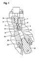
- Die Erfindung wird nun anhand der Figur beschrieben.
- Die einzige Figur zeigt einen Querschnitt durch ein Kompressorbauteil mit dem erfindungsgemäßen Schmiermittelabscheider. Im Schnitt ist ein Teil eines Kompressorbauteils 1, beispielsweise ein Schnitt durch den Zylinderkopf eines Kompressors, dargestellt. Im Schnitt ist in diesem Kompressorbauteil 1 eine Stufenbohrung mit einem großen Durchmesser 3 und einem kleineren Durchmesser 5 dargestellt. In dem durchmesserkleineren Teil 5 der Stufenbohrung ist eine Hülse 7 eingebracht, welche durch Befestigungstechniken wie Einpressen, Einkleben, Einschrauben oder ähnliches in der Stufenbohrung befestigt werden kann. Die Hülse 7 ragt mit einem Teil 9 in den Bereich der Stufenbohrung mit dem größeren Durchmesser 3 und stellt somit mit der Stufenbohrung einen doppelwandigen, zylindrischen Körper in diesem Abschnitt dar.
- Tangential mündet in den Wandungsbereich zwischen dem großen Durchmesser 3 der Stufenbohrung und dem Außendurchmesser des Hülsenabschnittes 9 eine Öffnung 11, welche aus dem Auslassdruckbereich innerhalb des Zylinderkopfes des Klimakompressors kommt und damit das unter Hochdruck stehende Kältemittel in diesen Bereich tangential einströmen lässt. Da das durch die Öffnung 11 tangential einströmende Kältemittel auch Schmiermittel zur Schmierung des Kompressors enthält, wird sich um die Hülse im Bereich des Abschnittes 9 herum eine schraubenförmige Schmiermittelbewegung ergeben, wodurch das Schmiermittel durch Fliehkräfte sich außen an der Wandung des großen Stufenbohrungsdurchmessers 3 absetzen kann und nach unten in den Bereich 13 der Stufenbohrung geleitet werden kann. Das Kältemittel selber wird durch die Hülse im Bereich 15 innen in den Bereich 17 einströmen, welcher den Auslassbereich des Kompressors darstellt. Im Auslassbereich 17 des Kompressors ist ein Anschlussbauteil 19 dargestellt, welches eine Leitungsverbindung zwischen der übrigen Klimaanlage und dem hier dargestellten Klimakompressor herstellt. Im unteren Bereich 13 des durchmessergrößeren Bereichs 3 der Stufenbohrung ist im Schnitt ein Ventilkörper 21 dargestellt, welcher ein Regelventil zur Regelung des Triebraumdruckes darstellt. Da dieses Regelventil einen Teil des Kältemittelstroms direkt in den Triebraum leitet und damit auch den Hauptanteil des Schmiermittels, der sich hier in dem erfindungsgemäßen Schmiermittelabscheider abgeschieden hat, wird somit auf kürzestem Weg der Triebraum mit dem entsprechenden Schmiermittel versorgt, während das von dem Schmiermittel weitestgehend befreite Kältemittel in einem Hauptstrom durch den Innenraum 15 der Hülse 7 dem Auslass 17 zur Klimaanlage hin zugeführt wird. Das Regelventil 21 besitzt Dichtungsringe 23 und 25 und dichtet damit in seiner Funktion gleichzeitig die Stufenbohrung des Schmiermittelabscheiders mit ab.
- Die hier dargestellte Ausführung des Schmiermittelabscheiders hebt sich von den im Stand der Technik bekannten Schmiermittelabscheidern insbesondere dadurch ab, dass durch eine einzige Stufenbohrung ein sehr kostengünstiges Fertigungsverfahren dargestellt werden kann, wobei dann durch Einsatz eines sehr einfachen Bauteils wie der Hülse 7 die Funktion des Schmiermittelabscheiders einfach, schnell und kostengünstig realisiert werden kann, ohne dass beispielsweise gestufte Drehteile oder ähnliche Bauteile die Funktion des Schmiermittelabscheiders, wie im Stand der Technik dargestellt, übernehmen.
-
- 1
- Kompressorbauteil (Gehäusebauteil)
- 3
- großer Durchmesser
- 5
- kleiner Durchmesser
- 7
- Hülse
- 9
- Teil der Hülse, Hülsenabschnitt
- 11
- Öffnung (Bohrung)
- 13
- Bereich der Stufenbohrung (Teil der Stufenbohrung)
- 15
- Bereich
- 17
- Bereich, Auslassbereich des Kompressors (Auslassanschluss)
- 19
- Anschlussbauteil (Leitungsverbindung)
- 21
- Ventilkörper (Regelventil, Ventil)
- 23
- Dichtungsring
- 25
- Dichtungsring
Claims (9)
- Kompressor, wie Klimakompressor für Kraftfahrzeuge, mit einem Triebwerk zum Ansaugen und Komprimieren eines Kältemittels und mit einem Schmiermittelabscheider, welcher im Entladedruckbereich des Kompressors Schmiermittel aus dem Kältemittel abscheidet, wobei das Schmiermittel mittels eines vom Hochdruck-Kältemittelstrom abgezweigten Teilstroms dem Triebwerk zugeführt wird, wobei der Kompressor im Entladedruckbereich in einem Gehäusebauteil (1) eine Stufenbohrung mit einem kleinen (5) und einem großen Durchmesser (3) aufweist, gekennzeichnet durch eine in dem kleinen Durchmesser (5) eingesetzte einfache Hülse (7) mit einem einzigen Durchmesser, welche teilweise in den Teil (13) der Stufenbohrung mit dem großen Durchmesser (3) hereinragt.
- Kompressor nach Anspruch 1, dadurch gekennzeichnet, dass in die Stufenbohrung in dem Bereich (13), der durch den großen Durchmesser (3) und die hereinragende Hülse (7) gebildet wird, tangential am Außenumfang der Bohrungswand mit dem großen Durchmesser (3) eine Bohrung (11) aus dem unmittelbaren Auslassdruckbereich des Zylinderkopfs einmündet.
- Kompressor nach Anspruch 1 oder Anspruch 2, dadurch gekennzeichnet, dass die Stufenbohrung als separate Bohrung im wesentlichen radial von außen in den Zylinderkopf eingebracht ist.
- Kompressor nach Anspruch 1 oder Anspruch 2 oder Anspruch 3, dadurch gekennzeichnet, dass die Stufenbohrung zusätzlich ein Ventil (21) aufnimmt, welches die Bohrung verschließt und damit nach außen abdichtet.
- Kompressor nach Anspruch 4, dadurch gekennzeichnet, dass das Ventil (21) ein Regelventil darstellt, welches den abgezweigten Teilstrom vom Entladedruckbereich zum Triebraum und damit auch den Triebraumdruck regelt.
- Kompressor nach Anspruch 4, dadurch gekennzeichnet, dass das Ventil ein Druckbegrenzungsventil darstellt, welches bei Überschreiten eines maximal zulässigen Drucks den Druck in den Triebraum abregelt.
- Kompressor nach einem der vorhergehenden Ansprüche, dadurch gekennzeichnet, dass die Stufenbohrung mit ihrem Bereich des kleinen Durchmessers (5) in eine zweite Bohrung mündet, welche den Auslassanschluss (17) für den Entladedruckbereich des Kältemittels darstellt.
- Kompressor nach einem der vorhergehenden Ansprüche, dadurch gekennzeichnet, dass die Montage der Hülse (7) in dem kleineren Durchmesserbereich (5) der Stufenbohrung von der Ventilseite her erfolgen kann, beispielsweise durch Einpressen.
- Kompressor nach einem der vorhergehenden Ansprüche, dadurch gekennzeichnet, dass der Durchmesser des Auslassanschlusses für den Entladedruckbereich des Kältemittels sehr klein gehalten werden kann, beispielsweise im Bereich von 5-7 mm.
Applications Claiming Priority (2)
| Application Number | Priority Date | Filing Date | Title |
|---|---|---|---|
| DE102004040825 | 2004-08-24 | ||
| PCT/DE2005/001387 WO2006021180A1 (de) | 2004-08-24 | 2005-08-05 | Kompressor |
Publications (2)
| Publication Number | Publication Date |
|---|---|
| EP1784573A1 EP1784573A1 (de) | 2007-05-16 |
| EP1784573B1 true EP1784573B1 (de) | 2013-11-20 |
Family
ID=35063343
Family Applications (1)
| Application Number | Title | Priority Date | Filing Date |
|---|---|---|---|
| EP05774251.2A Expired - Lifetime EP1784573B1 (de) | 2004-08-24 | 2005-08-05 | Kompressor |
Country Status (6)
| Country | Link |
|---|---|
| US (1) | US8353681B2 (de) |
| EP (1) | EP1784573B1 (de) |
| JP (1) | JP4805932B2 (de) |
| CN (1) | CN101006274B (de) |
| DE (2) | DE112005002716A5 (de) |
| WO (1) | WO2006021180A1 (de) |
Families Citing this family (2)
| Publication number | Priority date | Publication date | Assignee | Title |
|---|---|---|---|---|
| US9856866B2 (en) | 2011-01-28 | 2018-01-02 | Wabtec Holding Corp. | Oil-free air compressor for rail vehicles |
| DE112014005667A5 (de) * | 2013-12-13 | 2016-09-29 | Magna Powertrain Bad Homburg GmbH | Klimakompressor |
Family Cites Families (25)
| Publication number | Priority date | Publication date | Assignee | Title |
|---|---|---|---|---|
| KR970004811B1 (ko) * | 1993-06-08 | 1997-04-04 | 가부시끼가이샤 도요다 지도쇽끼 세이샤꾸쇼 | 무클러치 편측 피스톤식 가변 용량 압축기 및 그 용량 제어방법 |
| US5577894A (en) * | 1993-11-05 | 1996-11-26 | Kabushiki Kaisha Toyoda Jidoshokki Seisakusho | Piston type variable displacement compressor |
| JPH0960591A (ja) * | 1995-08-21 | 1997-03-04 | Toyota Autom Loom Works Ltd | 圧縮機のオイル分離機構 |
| US6203284B1 (en) * | 1995-10-26 | 2001-03-20 | Kabushiki Kaisha Toyoda Jidoshokki Seisakusho | Valve arrangement at the discharge chamber of a variable displacement compressor |
| JPH10196540A (ja) * | 1997-01-10 | 1998-07-31 | Toyota Autom Loom Works Ltd | 圧縮機 |
| KR100207792B1 (ko) * | 1997-02-24 | 1999-07-15 | 윤종용 | 밀폐형 압축기 |
| JPH10311277A (ja) | 1997-05-13 | 1998-11-24 | Zexel Corp | 冷媒圧縮機 |
| EP1418337B1 (de) * | 1997-08-29 | 2007-12-19 | Denso Corporation | Spiralverdichter |
| JP2000346241A (ja) * | 1999-06-07 | 2000-12-15 | Toyota Autom Loom Works Ltd | 逆止弁 |
| JP4016556B2 (ja) * | 1999-12-17 | 2007-12-05 | 株式会社豊田自動織機 | 圧縮機 |
| JP3721933B2 (ja) * | 2000-04-17 | 2005-11-30 | 株式会社デンソー | 圧縮機 |
| JP3864673B2 (ja) * | 2000-06-27 | 2007-01-10 | 株式会社豊田自動織機 | 圧縮機 |
| AU2002216928A1 (en) | 2000-11-23 | 2002-06-03 | Luk Fahrzeug-Hydraulik Gmbh And Co. Kg | Air-conditioning system comprising a lubricant separator and a compressor |
| JP4292552B2 (ja) * | 2002-05-14 | 2009-07-08 | 株式会社ヴァレオサーマルシステムズ | 往復動型圧縮機 |
| JP2004036583A (ja) * | 2002-07-05 | 2004-02-05 | Denso Corp | 圧縮機 |
| ATE478261T1 (de) * | 2003-09-30 | 2010-09-15 | Sanyo Electric Co | Rotationsverdichter, klimaanlage für ein fahrzeug und wassererhitzer, die den verdichter beinhalten |
| JP2005171859A (ja) * | 2003-12-10 | 2005-06-30 | Sanden Corp | 圧縮機 |
| JP4286175B2 (ja) * | 2004-04-13 | 2009-06-24 | サンデン株式会社 | 圧縮機 |
| JP2007162561A (ja) * | 2005-12-13 | 2007-06-28 | Toyota Industries Corp | 冷媒圧縮機 |
| JP4806262B2 (ja) * | 2006-01-05 | 2011-11-02 | サンデン株式会社 | 圧縮機 |
| JP2007192201A (ja) * | 2006-01-23 | 2007-08-02 | Toyota Industries Corp | 圧縮機における油回収構造 |
| JP4858409B2 (ja) * | 2007-11-05 | 2012-01-18 | 株式会社豊田自動織機 | 可変容量圧縮機 |
| JP2010096167A (ja) * | 2007-11-29 | 2010-04-30 | Toyota Industries Corp | 圧縮機におけるフィルタの取付構造 |
| EP2105614B1 (de) * | 2008-03-25 | 2012-12-26 | Calsonic Kansei Corporation | Gaskompressor |
| JP5434937B2 (ja) * | 2011-02-22 | 2014-03-05 | 株式会社豊田自動織機 | 圧縮機 |
-
2005
- 2005-08-05 JP JP2007528576A patent/JP4805932B2/ja not_active Expired - Fee Related
- 2005-08-05 WO PCT/DE2005/001387 patent/WO2006021180A1/de not_active Ceased
- 2005-08-05 EP EP05774251.2A patent/EP1784573B1/de not_active Expired - Lifetime
- 2005-08-05 DE DE112005002716T patent/DE112005002716A5/de not_active Withdrawn
- 2005-08-05 CN CN200580028583.8A patent/CN101006274B/zh not_active Expired - Fee Related
- 2005-08-05 US US11/660,619 patent/US8353681B2/en not_active Expired - Fee Related
- 2005-08-05 DE DE102005036896A patent/DE102005036896A1/de not_active Ceased
Also Published As
| Publication number | Publication date |
|---|---|
| DE112005002716A5 (de) | 2007-08-09 |
| US8353681B2 (en) | 2013-01-15 |
| JP2008510917A (ja) | 2008-04-10 |
| DE102005036896A1 (de) | 2006-03-02 |
| WO2006021180A1 (de) | 2006-03-02 |
| EP1784573A1 (de) | 2007-05-16 |
| CN101006274B (zh) | 2013-05-29 |
| JP4805932B2 (ja) | 2011-11-02 |
| US20080034783A1 (en) | 2008-02-14 |
| CN101006274A (zh) | 2007-07-25 |
Similar Documents
| Publication | Publication Date | Title |
|---|---|---|
| DE102008026389B4 (de) | Taumelscheiben-Kompressor mit variabler Kapazität | |
| DE102012104045A1 (de) | Kältemittelscrollverdichter für Kraftfahrzeugklimaanlagen | |
| EP0925446B2 (de) | Radialkolbenpumpe zur kraftstoffhochdruckversorgung | |
| DE112015004113T5 (de) | Kompressor mit Ölrückführeinheit | |
| DE102016105302A1 (de) | Steuerstromregelventil, insbesondere für Scrollverdichter in Fahrzeugklimaanlagen oder Wärmepumpen | |
| EP3615800B1 (de) | Verdichter, druckluftversorgungsanlage zum betreiben einer pneumatikanlage und verfahren zum betreiben einer druckluftversorgungsanlage | |
| DE102009042620A1 (de) | Adapter sowie Pumpenanlage | |
| WO2011063870A2 (de) | Schraubenspindelpumpe mit integriertem druckbegrenzungsventil | |
| DE10305310B4 (de) | Vorrichtung zur Dämpfung von Druckpulsationen | |
| DE102010018203A1 (de) | Druckspeicheranordnung für ein Nockenwellenverstellsystem | |
| DE102016217446A1 (de) | Ladeeinrichtung | |
| DE102018217911A1 (de) | Verdichtermodul sowie elektromotorischer Kältemittelverdichter | |
| DE102005036896A1 (de) | Kompressor | |
| DE10305781B4 (de) | Mehrstufige Schmierölpumpe | |
| DE102019101855A1 (de) | Spiralverdichter mit Ölrückführeinheit | |
| DE102020133327B4 (de) | Pumpenanordnung | |
| EP1948938B1 (de) | Pumpe mit zylindrischer kühlbuchse | |
| DE102016203074B3 (de) | Getriebemotor | |
| EP1264965A2 (de) | Lagergehäuse eines Abgasturboladers für eine Brennkraftmaschine | |
| EP1315906B1 (de) | Kolbenkompressor mit dynamisch massenausgeglichener kurbelwelle, insbesondere für schienenfahrzeuge (lösbare ausgleichsmasse) | |
| DE102012017325B4 (de) | Abgasturbolader | |
| EP3837439B1 (de) | Hubkolbenkompressor | |
| DE102010051141B3 (de) | Regelkolbenanordnung | |
| WO2022058304A1 (de) | Scrollverdichter für kältemittel einer fahrzeugklimaanlage | |
| DE10156785A1 (de) | Klimaanlage mit Schmiermittelabscheider und Verdichter |
Legal Events
| Date | Code | Title | Description |
|---|---|---|---|
| PUAI | Public reference made under article 153(3) epc to a published international application that has entered the european phase |
Free format text: ORIGINAL CODE: 0009012 |
|
| 17P | Request for examination filed |
Effective date: 20070326 |
|
| AK | Designated contracting states |
Kind code of ref document: A1 Designated state(s): AT BE BG CH CY CZ DE DK EE ES FI FR GB GR HU IE IS IT LI LT LU LV MC NL PL PT RO SE SI SK TR |
|
| RAP1 | Party data changed (applicant data changed or rights of an application transferred) |
Owner name: IXETIC MAC GMBH |
|
| DAX | Request for extension of the european patent (deleted) | ||
| 17Q | First examination report despatched |
Effective date: 20090630 |
|
| RAP1 | Party data changed (applicant data changed or rights of an application transferred) |
Owner name: IXETIC BAD HOMBURG GMBH |
|
| RAP1 | Party data changed (applicant data changed or rights of an application transferred) |
Owner name: IXETIC BAD HOMBURG GMBH |
|
| GRAP | Despatch of communication of intention to grant a patent |
Free format text: ORIGINAL CODE: EPIDOSNIGR1 |
|
| INTG | Intention to grant announced |
Effective date: 20130819 |
|
| GRAS | Grant fee paid |
Free format text: ORIGINAL CODE: EPIDOSNIGR3 |
|
| GRAA | (expected) grant |
Free format text: ORIGINAL CODE: 0009210 |
|
| AK | Designated contracting states |
Kind code of ref document: B1 Designated state(s): AT BE BG CH CY CZ DE DK EE ES FI FR GB GR HU IE IS IT LI LT LU LV MC NL PL PT RO SE SI SK TR |
|
| REG | Reference to a national code |
Ref country code: GB Ref legal event code: FG4D Free format text: NOT ENGLISH |
|
| REG | Reference to a national code |
Ref country code: CH Ref legal event code: EP |
|
| REG | Reference to a national code |
Ref country code: AT Ref legal event code: REF Ref document number: 641808 Country of ref document: AT Kind code of ref document: T Effective date: 20131215 |
|
| REG | Reference to a national code |
Ref country code: IE Ref legal event code: FG4D Free format text: LANGUAGE OF EP DOCUMENT: GERMAN |
|
| REG | Reference to a national code |
Ref country code: DE Ref legal event code: R096 Ref document number: 502005014086 Country of ref document: DE Effective date: 20140109 |
|
| REG | Reference to a national code |
Ref country code: NL Ref legal event code: VDEP Effective date: 20131120 |
|
| REG | Reference to a national code |
Ref country code: LT Ref legal event code: MG4D |
|
| PG25 | Lapsed in a contracting state [announced via postgrant information from national office to epo] |
Ref country code: IS Free format text: LAPSE BECAUSE OF FAILURE TO SUBMIT A TRANSLATION OF THE DESCRIPTION OR TO PAY THE FEE WITHIN THE PRESCRIBED TIME-LIMIT Effective date: 20140320 Ref country code: SE Free format text: LAPSE BECAUSE OF FAILURE TO SUBMIT A TRANSLATION OF THE DESCRIPTION OR TO PAY THE FEE WITHIN THE PRESCRIBED TIME-LIMIT Effective date: 20131120 Ref country code: NL Free format text: LAPSE BECAUSE OF FAILURE TO SUBMIT A TRANSLATION OF THE DESCRIPTION OR TO PAY THE FEE WITHIN THE PRESCRIBED TIME-LIMIT Effective date: 20131120 Ref country code: FI Free format text: LAPSE BECAUSE OF FAILURE TO SUBMIT A TRANSLATION OF THE DESCRIPTION OR TO PAY THE FEE WITHIN THE PRESCRIBED TIME-LIMIT Effective date: 20131120 Ref country code: LT Free format text: LAPSE BECAUSE OF FAILURE TO SUBMIT A TRANSLATION OF THE DESCRIPTION OR TO PAY THE FEE WITHIN THE PRESCRIBED TIME-LIMIT Effective date: 20131120 |
|
| REG | Reference to a national code |
Ref country code: DE Ref legal event code: R081 Ref document number: 502005014086 Country of ref document: DE Owner name: MAGNA POWERTRAIN BAD HOMBURG GMBH, DE Free format text: FORMER OWNER: IXETIC BAD HOMBURG GMBH, 61352 BAD HOMBURG, DE Effective date: 20140409 |
|
| PG25 | Lapsed in a contracting state [announced via postgrant information from national office to epo] |
Ref country code: LV Free format text: LAPSE BECAUSE OF FAILURE TO SUBMIT A TRANSLATION OF THE DESCRIPTION OR TO PAY THE FEE WITHIN THE PRESCRIBED TIME-LIMIT Effective date: 20131120 Ref country code: ES Free format text: LAPSE BECAUSE OF FAILURE TO SUBMIT A TRANSLATION OF THE DESCRIPTION OR TO PAY THE FEE WITHIN THE PRESCRIBED TIME-LIMIT Effective date: 20131120 |
|
| PG25 | Lapsed in a contracting state [announced via postgrant information from national office to epo] |
Ref country code: PT Free format text: LAPSE BECAUSE OF FAILURE TO SUBMIT A TRANSLATION OF THE DESCRIPTION OR TO PAY THE FEE WITHIN THE PRESCRIBED TIME-LIMIT Effective date: 20140320 |
|
| PG25 | Lapsed in a contracting state [announced via postgrant information from national office to epo] |
Ref country code: EE Free format text: LAPSE BECAUSE OF FAILURE TO SUBMIT A TRANSLATION OF THE DESCRIPTION OR TO PAY THE FEE WITHIN THE PRESCRIBED TIME-LIMIT Effective date: 20131120 |
|
| REG | Reference to a national code |
Ref country code: DE Ref legal event code: R097 Ref document number: 502005014086 Country of ref document: DE |
|
| PG25 | Lapsed in a contracting state [announced via postgrant information from national office to epo] |
Ref country code: RO Free format text: LAPSE BECAUSE OF FAILURE TO SUBMIT A TRANSLATION OF THE DESCRIPTION OR TO PAY THE FEE WITHIN THE PRESCRIBED TIME-LIMIT Effective date: 20131120 Ref country code: PL Free format text: LAPSE BECAUSE OF FAILURE TO SUBMIT A TRANSLATION OF THE DESCRIPTION OR TO PAY THE FEE WITHIN THE PRESCRIBED TIME-LIMIT Effective date: 20131120 Ref country code: CZ Free format text: LAPSE BECAUSE OF FAILURE TO SUBMIT A TRANSLATION OF THE DESCRIPTION OR TO PAY THE FEE WITHIN THE PRESCRIBED TIME-LIMIT Effective date: 20131120 Ref country code: SK Free format text: LAPSE BECAUSE OF FAILURE TO SUBMIT A TRANSLATION OF THE DESCRIPTION OR TO PAY THE FEE WITHIN THE PRESCRIBED TIME-LIMIT Effective date: 20131120 |
|
| PLBE | No opposition filed within time limit |
Free format text: ORIGINAL CODE: 0009261 |
|
| STAA | Information on the status of an ep patent application or granted ep patent |
Free format text: STATUS: NO OPPOSITION FILED WITHIN TIME LIMIT |
|
| PG25 | Lapsed in a contracting state [announced via postgrant information from national office to epo] |
Ref country code: DK Free format text: LAPSE BECAUSE OF FAILURE TO SUBMIT A TRANSLATION OF THE DESCRIPTION OR TO PAY THE FEE WITHIN THE PRESCRIBED TIME-LIMIT Effective date: 20131120 |
|
| 26N | No opposition filed |
Effective date: 20140821 |
|
| PGFP | Annual fee paid to national office [announced via postgrant information from national office to epo] |
Ref country code: FR Payment date: 20140821 Year of fee payment: 10 |
|
| REG | Reference to a national code |
Ref country code: DE Ref legal event code: R097 Ref document number: 502005014086 Country of ref document: DE Effective date: 20140821 |
|
| PGFP | Annual fee paid to national office [announced via postgrant information from national office to epo] |
Ref country code: IT Payment date: 20140826 Year of fee payment: 10 |
|
| PG25 | Lapsed in a contracting state [announced via postgrant information from national office to epo] |
Ref country code: SI Free format text: LAPSE BECAUSE OF FAILURE TO SUBMIT A TRANSLATION OF THE DESCRIPTION OR TO PAY THE FEE WITHIN THE PRESCRIBED TIME-LIMIT Effective date: 20131120 |
|
| PG25 | Lapsed in a contracting state [announced via postgrant information from national office to epo] |
Ref country code: LU Free format text: LAPSE BECAUSE OF FAILURE TO SUBMIT A TRANSLATION OF THE DESCRIPTION OR TO PAY THE FEE WITHIN THE PRESCRIBED TIME-LIMIT Effective date: 20140805 Ref country code: MC Free format text: LAPSE BECAUSE OF FAILURE TO SUBMIT A TRANSLATION OF THE DESCRIPTION OR TO PAY THE FEE WITHIN THE PRESCRIBED TIME-LIMIT Effective date: 20131120 |
|
| REG | Reference to a national code |
Ref country code: CH Ref legal event code: PL |
|
| GBPC | Gb: european patent ceased through non-payment of renewal fee |
Effective date: 20140805 |
|
| PG25 | Lapsed in a contracting state [announced via postgrant information from national office to epo] |
Ref country code: CH Free format text: LAPSE BECAUSE OF NON-PAYMENT OF DUE FEES Effective date: 20140831 Ref country code: BE Free format text: LAPSE BECAUSE OF NON-PAYMENT OF DUE FEES Effective date: 20140831 Ref country code: LI Free format text: LAPSE BECAUSE OF NON-PAYMENT OF DUE FEES Effective date: 20140831 |
|
| REG | Reference to a national code |
Ref country code: IE Ref legal event code: MM4A |
|
| PG25 | Lapsed in a contracting state [announced via postgrant information from national office to epo] |
Ref country code: GB Free format text: LAPSE BECAUSE OF NON-PAYMENT OF DUE FEES Effective date: 20140805 |
|
| PG25 | Lapsed in a contracting state [announced via postgrant information from national office to epo] |
Ref country code: IE Free format text: LAPSE BECAUSE OF NON-PAYMENT OF DUE FEES Effective date: 20140805 |
|
| REG | Reference to a national code |
Ref country code: AT Ref legal event code: MM01 Ref document number: 641808 Country of ref document: AT Kind code of ref document: T Effective date: 20140805 |
|
| PGFP | Annual fee paid to national office [announced via postgrant information from national office to epo] |
Ref country code: DE Payment date: 20150821 Year of fee payment: 11 |
|
| PG25 | Lapsed in a contracting state [announced via postgrant information from national office to epo] |
Ref country code: AT Free format text: LAPSE BECAUSE OF NON-PAYMENT OF DUE FEES Effective date: 20140805 |
|
| PG25 | Lapsed in a contracting state [announced via postgrant information from national office to epo] |
Ref country code: IT Free format text: LAPSE BECAUSE OF NON-PAYMENT OF DUE FEES Effective date: 20150805 |
|
| PG25 | Lapsed in a contracting state [announced via postgrant information from national office to epo] |
Ref country code: BG Free format text: LAPSE BECAUSE OF FAILURE TO SUBMIT A TRANSLATION OF THE DESCRIPTION OR TO PAY THE FEE WITHIN THE PRESCRIBED TIME-LIMIT Effective date: 20131120 |
|
| REG | Reference to a national code |
Ref country code: FR Ref legal event code: ST Effective date: 20160429 |
|
| PG25 | Lapsed in a contracting state [announced via postgrant information from national office to epo] |
Ref country code: CY Free format text: LAPSE BECAUSE OF FAILURE TO SUBMIT A TRANSLATION OF THE DESCRIPTION OR TO PAY THE FEE WITHIN THE PRESCRIBED TIME-LIMIT Effective date: 20131120 Ref country code: GR Free format text: LAPSE BECAUSE OF FAILURE TO SUBMIT A TRANSLATION OF THE DESCRIPTION OR TO PAY THE FEE WITHIN THE PRESCRIBED TIME-LIMIT Effective date: 20140221 |
|
| PG25 | Lapsed in a contracting state [announced via postgrant information from national office to epo] |
Ref country code: TR Free format text: LAPSE BECAUSE OF FAILURE TO SUBMIT A TRANSLATION OF THE DESCRIPTION OR TO PAY THE FEE WITHIN THE PRESCRIBED TIME-LIMIT Effective date: 20131120 Ref country code: HU Free format text: LAPSE BECAUSE OF FAILURE TO SUBMIT A TRANSLATION OF THE DESCRIPTION OR TO PAY THE FEE WITHIN THE PRESCRIBED TIME-LIMIT; INVALID AB INITIO Effective date: 20050805 |
|
| PG25 | Lapsed in a contracting state [announced via postgrant information from national office to epo] |
Ref country code: FR Free format text: LAPSE BECAUSE OF NON-PAYMENT OF DUE FEES Effective date: 20150831 |
|
| REG | Reference to a national code |
Ref country code: DE Ref legal event code: R119 Ref document number: 502005014086 Country of ref document: DE |
|
| PG25 | Lapsed in a contracting state [announced via postgrant information from national office to epo] |
Ref country code: DE Free format text: LAPSE BECAUSE OF NON-PAYMENT OF DUE FEES Effective date: 20170301 |