EP1784110B1 - Aspirateur muni d'une carte a circuits imprimes retenue sans contrainte - Google Patents
Aspirateur muni d'une carte a circuits imprimes retenue sans contrainte Download PDFInfo
- Publication number
- EP1784110B1 EP1784110B1 EP05777817A EP05777817A EP1784110B1 EP 1784110 B1 EP1784110 B1 EP 1784110B1 EP 05777817 A EP05777817 A EP 05777817A EP 05777817 A EP05777817 A EP 05777817A EP 1784110 B1 EP1784110 B1 EP 1784110B1
- Authority
- EP
- European Patent Office
- Prior art keywords
- vacuum cleaner
- circuit board
- electrical component
- mount
- printed circuit
- Prior art date
- Legal status (The legal status is an assumption and is not a legal conclusion. Google has not performed a legal analysis and makes no representation as to the accuracy of the status listed.)
- Expired - Lifetime
Links
Images
Classifications
-
- A—HUMAN NECESSITIES
- A47—FURNITURE; DOMESTIC ARTICLES OR APPLIANCES; COFFEE MILLS; SPICE MILLS; SUCTION CLEANERS IN GENERAL
- A47L—DOMESTIC WASHING OR CLEANING; SUCTION CLEANERS IN GENERAL
- A47L9/00—Details or accessories of suction cleaners, e.g. mechanical means for controlling the suction or for effecting pulsating action; Storing devices specially adapted to suction cleaners or parts thereof; Carrying-vehicles specially adapted for suction cleaners
- A47L9/28—Installation of the electric equipment, e.g. adaptation or attachment to the suction cleaner; Controlling suction cleaners by electric means
-
- A—HUMAN NECESSITIES
- A47—FURNITURE; DOMESTIC ARTICLES OR APPLIANCES; COFFEE MILLS; SPICE MILLS; SUCTION CLEANERS IN GENERAL
- A47L—DOMESTIC WASHING OR CLEANING; SUCTION CLEANERS IN GENERAL
- A47L9/00—Details or accessories of suction cleaners, e.g. mechanical means for controlling the suction or for effecting pulsating action; Storing devices specially adapted to suction cleaners or parts thereof; Carrying-vehicles specially adapted for suction cleaners
- A47L9/26—Incorporation of winding devices for electric cables
-
- H—ELECTRICITY
- H05—ELECTRIC TECHNIQUES NOT OTHERWISE PROVIDED FOR
- H05K—PRINTED CIRCUITS; CASINGS OR CONSTRUCTIONAL DETAILS OF ELECTRIC APPARATUS; MANUFACTURE OF ASSEMBLAGES OF ELECTRICAL COMPONENTS
- H05K3/00—Apparatus or processes for manufacturing printed circuits
- H05K3/30—Assembling printed circuits with electric components, e.g. with resistors
- H05K3/301—Assembling printed circuits with electric components, e.g. with resistors by means of a mounting structure
Definitions
- the invention relates to a vacuum cleaner with a printed circuit board according to the preamble of claim 1.
- a vacuum cleaner in which the circuit board is arranged on a support member. Furthermore, a serving for switching on / off the blower unit switch is attached to the support member and connected by means of insertion tabs with the conductor tracks of the circuit board. The operation of the switch via a button which acts by means of a plunger approach to the switch plunger of the switch. By attaching the switch on the support part, the actuating forces are absorbed by the support member, so that the circuit board is not directly loaded by the actuating forces.
- the disadvantage here is that the circuit board is arranged on the support member.
- Actuating forces which are introduced into the switch can indeed be introduced into the support member, without acting directly on the circuit board, however, the actuation forces introduced into the support part can still be partially transmitted to the circuit board, since this is further arranged on the support member.
- the disadvantage here is that despite the application of a support member for the switch actuating forces are at least partially continue to be transferred to the circuit board.
- the object of the invention is to keep the initiated during actuation of the switch actuating forces away from the circuit board.
- the object of the invention is achieved in a generic vacuum cleaner characterized in that the circuit board is kept separated from the holder mechanically separated from the electrical contacts of the electrical component. By completely mechanically separating the holder for the electrical component from the printed circuit board, it is ensured that no actuating forces are transmitted to the printed circuit board. Due to the separation of the holder and circuit board according to the invention, damage to the printed circuit board, for example, due to stress cracks is avoided and the service life of the vacuum cleaner is thereby prolonged.
- the holder has the electrical component encompassing latching hooks, through which the electrical component is held in the holder.
- the electrical component can preferably be snapped together with the circuit board into the holder and is held there reliably mechanically, without having to provide separate fastening means.
- the holder is provided on a housing part of the vacuum cleaner.
- the housing part may, for example, be a partition between a fan room and a receiving space for a cable drum.
- the circuit board By attaching or snapping the electrical component in the holder the circuit board is fixed in the vacuum cleaner at the same time.
- the electrical component is mechanically connected to the circuit board only via its electrical contacts. Since the printed circuit board has only a very low weight and is not exposed to any further mechanical stresses, the printed circuit board can be held in sufficient manner alone via the electrical contacts of the electrical component in the vacuum cleaner.
- an additional holding means or support means is unnecessary and thus the number of parts for the vacuum cleaner is reduced.
- the holder may be provided instead of on a housing part on a supporting structure of a cable drum mounted in the housing of the vacuum cleaner.
- the electrical component such as switches or potentiometers
- the electrical component can be used in a holder which is provided on the support structure of a cable drum.
- the support structure forms part of the fixed part of the cable drum on the example.
- the fixed bearing pin of the rotatable drum is provided.
- the circuit board can be secured by means of a support against unwanted movement of the circuit board in a direction of movement from the circuit board level out.
- the support does not serve to absorb mechanical forces that are introduced via the electrical component, but the support should in particular be designed so that the circuit board is still held tension-free on the electrical component only via the electrical contacts. Rather, the support should serve to introduce undesired bending stresses between the printed circuit board and the electrical component, which could lead to bending stresses on the electrical contacts of the electrical component. Due to the inventive support of the circuit board against unwanted movement of the circuit board in a direction of movement from the circuit board level in particular a breakage of the electrical contacts of the electrical component is reliably prevented.
- the support is provided at an opposite end of the holder of the circuit board. So it can be ensured that even with minor unwanted movements of the circuit board, the support is already effective and the introduction of bending stresses in the electrical contacts of the electrical component can be prevented at an early stage.
- the support as a on the housing of the vacuum cleaner or on the support structure of the cable drum provided, the circuit board encompassing, latching hook is formed.
- the latching hook is not fixed to the circuit board, but surrounds the circuit board to form a slight gap, so that no stress in the circuit board can occur.
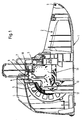
- a housing part 1 of a vacuum cleaner according to the invention is in FIG. 1 shown in longitudinal section.
- the housing part 1 has a dust chamber 2 in the front region.
- a dust filter bag or a dust collection box can be used.
- a hinge 3 is provided for a not shown pivotally mounted on the housing part 1 dust chamber cover.
- a receiving space 4 for a cable drum 5 adjoins the rear area of the vacuum cleaner at an end opposite the hinge 3.
- a holder 7 is formed on a housing wall 6 of the housing part 1.
- the holder 7 has two opposite latching hooks 8, which engage around an electrical component 9, namely a switch.
- the electrical component or the electrical switch has electrical contacts 10 which are connected to a printed circuit board 11.
- the circuit board 11 depends freely from the electrical contacts 10 down into the receiving space 4, without being attached to a further point of the housing part 1. Only on a side wall 12 of the housing part 1, a support 13 is provided, which prevents pivoting of the circuit board from the drawing plane out.
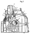
- FIG. 2 Analogous to FIG. 1 is in FIG. 2 the circuit board 11 held tension-free on the electrical component 9.
- the holder 7 is provided on a support structure 14 of the cable drum 5.
- the latching hooks 8 are mitangeformt to the support structure 14 and engage around the electrical component.
- On the circuit board 11, a rotary potentiometer 15 is further attached.
- the potentiometer 15 is actuated by an adjusting shaft 16, which adjusting shaft 16 is integrally formed on an actuating element 17.
- the actuating element 17 has a circular disk-shaped bottom plate 18, which on an actuating pin 19th of the electric switch 9 presses.
- the power of the vacuum cleaner can be adjusted by turning the actuating element 17 by the rotatable adjusting shaft 16 actuates the potentiometer.
- the vacuum cleaner is turned on and off by transmitting the pressing force from the bottom plate 18 to the operating pin 19 of the electric switch 9.
- the circuit board 11 may be additionally contacted directly with electrical terminals 20 electrically to the cable drum 5.
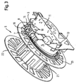
- the cable drum 5 has a rotatably mounted drum body 21. At the two opposite ends of the drum body 21, an outer drum flange 22 and an inner drum flange 23 are connected to the drum body 21.
- the drum body 21 is rotatably mounted on a bearing pin, not shown, which is integrally formed on the support structure 14.
- the holder 7 is formed on the support structure 14.
- the holder 7 comprises two opposite latching hooks 8, which surround the switch 9. For electrical switching on and off of the electrical switch 9, this has an actuating pin 19. About the actuating pin 19 electrical contacts are closed and opened.
- the electrical contacts 10 connect the switch 9 to the printed circuit board 11.
- the support 13 is formed, which forms as a backup for the circuit board against pivoting of the circuit board.
- a potentiometer 15 is also electrically contacted on the circuit board 11.
Landscapes
- Engineering & Computer Science (AREA)
- Mechanical Engineering (AREA)
- Electric Vacuum Cleaner (AREA)
- Filters For Electric Vacuum Cleaners (AREA)
- Nozzles For Electric Vacuum Cleaners (AREA)
- Combinations Of Printed Boards (AREA)
Claims (7)
- Aspirateur comportant un élément d'actionnement (17) pour un composant électrique (9) fixé dans un dispositif de fixation (7) dans l'aspirateur et dont les contacts électriques (10) sont fixés mécaniquement sur une carte de circuits imprimés (11) et sont reliés en faisant contact électrique à des pistes conductrices de la carte de circuits imprimés (11) pour la commande d'au moins une fonction de l'aspirateur, caractérisé en ce que la carte de circuits imprimés (11) est séparée mécaniquement du dispositif de fixation (7) et est retenue sans contrainte au niveau des contacts électriques (10) du composant électrique (9).
- Aspirateur selon la revendication 1, caractérisé en ce que le dispositif de fixation (7) comporte des crochets d'encliquetage (8) enserrant le composant électrique (9), par lesquels le composant électrique (9) est maintenu dans le dispositif de fixation (7).
- Aspirateur selon la revendication 1 ou 2, caractérisé en ce que le dispositif de fixation (7) est prévu sur une partie (1) du boîtier de l'aspirateur.
- Aspirateur selon la revendication 1 ou 2, caractérisé en ce que le dispositif de fixation (7) est prévu sur une structure de support (14) d'un touret de câble (5) logé dans le boîtier de l'aspirateur.
- Aspirateur selon l'une des revendications précédentes, caractérisé en ce que la carte de circuits imprimés (11) est protégée, au moyen d'un support (13), contre un déplacement intempestif de la carte de circuits imprimés (11) hors du plan de la carte de circuits imprimés dans un sens de déplacement.
- Aspirateur selon la revendication 5, caractérisé en ce que le support (13) est prévu à une extrémité de la carte de circuits imprimés (11) opposée au dispositif de fixation (7).
- Aspirateur selon la revendication 5 ou 6, caractérisé en ce que le support (13) se présente sous la forme d'un crochet d'encliquetage (8) prévu sur le boîtier de l'aspirateur ou sur la structure de support (14) du touret de câble (5) et enserrant la carte de circuits imprimés (11).
Priority Applications (1)
| Application Number | Priority Date | Filing Date | Title |
|---|---|---|---|
| PL05777817T PL1784110T3 (pl) | 2004-08-24 | 2005-08-05 | Odkurzacz z płytką drukowaną mocowaną bez naprężeń |
Applications Claiming Priority (2)
| Application Number | Priority Date | Filing Date | Title |
|---|---|---|---|
| DE102004040986A DE102004040986A1 (de) | 2004-08-24 | 2004-08-24 | Staubsauger mit einer spannungsfrei gehaltenen Leiterplatte |
| PCT/EP2005/053876 WO2006021501A1 (fr) | 2004-08-24 | 2005-08-05 | Aspirateur muni d'une carte a circuits imprimes retenue sans contrainte |
Publications (2)
| Publication Number | Publication Date |
|---|---|
| EP1784110A1 EP1784110A1 (fr) | 2007-05-16 |
| EP1784110B1 true EP1784110B1 (fr) | 2008-10-22 |
Family
ID=35134221
Family Applications (1)
| Application Number | Title | Priority Date | Filing Date |
|---|---|---|---|
| EP05777817A Expired - Lifetime EP1784110B1 (fr) | 2004-08-24 | 2005-08-05 | Aspirateur muni d'une carte a circuits imprimes retenue sans contrainte |
Country Status (7)
| Country | Link |
|---|---|
| EP (1) | EP1784110B1 (fr) |
| CN (1) | CN100563542C (fr) |
| AT (1) | ATE411765T1 (fr) |
| DE (2) | DE102004040986A1 (fr) |
| ES (1) | ES2314698T3 (fr) |
| PL (1) | PL1784110T3 (fr) |
| WO (1) | WO2006021501A1 (fr) |
Families Citing this family (3)
| Publication number | Priority date | Publication date | Assignee | Title |
|---|---|---|---|---|
| DE102008003351B4 (de) * | 2008-01-08 | 2011-05-19 | Miele & Cie. Kg | System zur Bestromung eines elektrischen Geräts mit einer Kabeltrommel, Staubsauger mit einem solchen System und Verfahren zur Herstellung eines Staubsaugers |
| JP5894896B2 (ja) * | 2012-09-28 | 2016-03-30 | シャープ株式会社 | 電気掃除機 |
| DE102017207491A1 (de) * | 2017-05-04 | 2018-11-08 | Bayerische Motoren Werke Aktiengesellschaft | Elektronikmodul |
Family Cites Families (5)
| Publication number | Priority date | Publication date | Assignee | Title |
|---|---|---|---|---|
| DE58900869D1 (de) * | 1988-10-17 | 1992-04-02 | Siemens Ag | Staubsauger mit einem drehzahlsteuerbaren geblaesemotor. |
| DE9100815U1 (de) * | 1990-02-05 | 1991-04-11 | Siemens AG, 8000 München | Staubsauger mit einem drehzahlsteuerbaren Gebläse |
| JP2882003B2 (ja) * | 1990-08-14 | 1999-04-12 | 松下電器産業株式会社 | 電気掃除機 |
| DE19801468A1 (de) * | 1998-01-16 | 1999-07-22 | Bosch Siemens Hausgeraete | Staubsauger |
| CN2577757Y (zh) * | 2002-10-24 | 2003-10-08 | 刘纹高 | 集成电路板吸尘器 |
-
2004
- 2004-08-24 DE DE102004040986A patent/DE102004040986A1/de not_active Withdrawn
-
2005
- 2005-08-05 AT AT05777817T patent/ATE411765T1/de not_active IP Right Cessation
- 2005-08-05 DE DE502005005761T patent/DE502005005761D1/de not_active Expired - Lifetime
- 2005-08-05 CN CNB2005800282651A patent/CN100563542C/zh not_active Expired - Fee Related
- 2005-08-05 WO PCT/EP2005/053876 patent/WO2006021501A1/fr not_active Ceased
- 2005-08-05 EP EP05777817A patent/EP1784110B1/fr not_active Expired - Lifetime
- 2005-08-05 ES ES05777817T patent/ES2314698T3/es not_active Expired - Lifetime
- 2005-08-05 PL PL05777817T patent/PL1784110T3/pl unknown
Also Published As
| Publication number | Publication date |
|---|---|
| PL1784110T3 (pl) | 2009-04-30 |
| ATE411765T1 (de) | 2008-11-15 |
| WO2006021501A1 (fr) | 2006-03-02 |
| CN101005786A (zh) | 2007-07-25 |
| DE102004040986A1 (de) | 2006-03-02 |
| EP1784110A1 (fr) | 2007-05-16 |
| ES2314698T3 (es) | 2009-03-16 |
| DE502005005761D1 (de) | 2008-12-04 |
| CN100563542C (zh) | 2009-12-02 |
Similar Documents
| Publication | Publication Date | Title |
|---|---|---|
| DE102010014143B4 (de) | Betätigungseinrichtung für eine elektrische Anschlussklemme | |
| DE10202371B4 (de) | Verschluss für Türen, Hauben, Klappen od. dgl., insbesondere von Fahrzeugen, wie Kraftfahrzeugen | |
| EP0995209B1 (fr) | Contacteur de commutation pour condensateur | |
| DE10020345B4 (de) | Stromversorgungsabschalteinrichtung | |
| DE102008019986B4 (de) | Anbauelement zur Montage an einem Schaltschrank-Rahmengestell | |
| EP3050168B1 (fr) | Connecteur électrique | |
| EP0778980A1 (fr) | Interrupteur a coulisse de levage | |
| DE202017107202U1 (de) | Anschlussvorrichtung zum Anschluss eines Leiterendes | |
| EP2720325B1 (fr) | Prise commutable | |
| DE10246014B4 (de) | Batterieklemme | |
| EP1784110B1 (fr) | Aspirateur muni d'une carte a circuits imprimes retenue sans contrainte | |
| EP0310840A1 (fr) | Prothèse auditive et son boîtier | |
| EP0450366A1 (fr) | Disjoncteur commandé par bouton-poussoir | |
| EP0806885A1 (fr) | Dispositif de fixation pour accessoriis pouvant être monté sur une prothèse auditive | |
| DE4136924C2 (de) | Motorträger für einen elektrischen Motor, insbesondere für eine Küchenmaschine | |
| DE10133879B4 (de) | Schaltgerät mit einem Schaltschloss | |
| DE4015619C2 (fr) | ||
| DE102009049709A1 (de) | Schraubklemme mit Abdeckung und Installationsschaltgerät | |
| DE29920404U1 (de) | Elektrischer Installationsschalter sowie Bauteilsystem und Glimmlampe für einen elektrischen Installationsschalter | |
| DE102020121590A1 (de) | Verfahren zur Montage eines Abschirmelementes; Montageeinheit für das Verfahren und elektronisches Gerät mit Abschirmelement in thermisch aktivierbarer Abtrenneinrichtung | |
| DE4137890A1 (de) | Elektrische schalteranordnung | |
| DE69507231T2 (de) | Elektrisches Gerät, insbesondere Schalter für Säulen- oder Reihenmontage | |
| EP1794767B1 (fr) | Commutateur electrique | |
| DE3617472C1 (en) | Switch | |
| DE29609824U1 (de) | Niederspannungs-Leistungsschalter mit einem Kontaktträger |
Legal Events
| Date | Code | Title | Description |
|---|---|---|---|
| PUAI | Public reference made under article 153(3) epc to a published international application that has entered the european phase |
Free format text: ORIGINAL CODE: 0009012 |
|
| 17P | Request for examination filed |
Effective date: 20070326 |
|
| AK | Designated contracting states |
Kind code of ref document: A1 Designated state(s): AT BE BG CH CY CZ DE DK EE ES FI FR GB GR HU IE IS IT LI LT LU LV MC NL PL PT RO SE SI SK TR |
|
| DAX | Request for extension of the european patent (deleted) | ||
| GRAP | Despatch of communication of intention to grant a patent |
Free format text: ORIGINAL CODE: EPIDOSNIGR1 |
|
| GRAS | Grant fee paid |
Free format text: ORIGINAL CODE: EPIDOSNIGR3 |
|
| GRAA | (expected) grant |
Free format text: ORIGINAL CODE: 0009210 |
|
| AK | Designated contracting states |
Kind code of ref document: B1 Designated state(s): AT BE BG CH CY CZ DE DK EE ES FI FR GB GR HU IE IS IT LI LT LU LV MC NL PL PT RO SE SI SK TR |
|
| REG | Reference to a national code |
Ref country code: GB Ref legal event code: FG4D Free format text: NOT ENGLISH |
|
| REG | Reference to a national code |
Ref country code: CH Ref legal event code: EP |
|
| REG | Reference to a national code |
Ref country code: IE Ref legal event code: FG4D Free format text: LANGUAGE OF EP DOCUMENT: GERMAN |
|
| REF | Corresponds to: |
Ref document number: 502005005761 Country of ref document: DE Date of ref document: 20081204 Kind code of ref document: P |
|
| REG | Reference to a national code |
Ref country code: ES Ref legal event code: FG2A Ref document number: 2314698 Country of ref document: ES Kind code of ref document: T3 |
|
| NLV1 | Nl: lapsed or annulled due to failure to fulfill the requirements of art. 29p and 29m of the patents act | ||
| PG25 | Lapsed in a contracting state [announced via postgrant information from national office to epo] |
Ref country code: BG Free format text: LAPSE BECAUSE OF FAILURE TO SUBMIT A TRANSLATION OF THE DESCRIPTION OR TO PAY THE FEE WITHIN THE PRESCRIBED TIME-LIMIT Effective date: 20090122 Ref country code: LT Free format text: LAPSE BECAUSE OF FAILURE TO SUBMIT A TRANSLATION OF THE DESCRIPTION OR TO PAY THE FEE WITHIN THE PRESCRIBED TIME-LIMIT Effective date: 20081022 |
|
| REG | Reference to a national code |
Ref country code: PL Ref legal event code: T3 |
|
| PG25 | Lapsed in a contracting state [announced via postgrant information from national office to epo] |
Ref country code: LV Free format text: LAPSE BECAUSE OF FAILURE TO SUBMIT A TRANSLATION OF THE DESCRIPTION OR TO PAY THE FEE WITHIN THE PRESCRIBED TIME-LIMIT Effective date: 20081022 Ref country code: PT Free format text: LAPSE BECAUSE OF FAILURE TO SUBMIT A TRANSLATION OF THE DESCRIPTION OR TO PAY THE FEE WITHIN THE PRESCRIBED TIME-LIMIT Effective date: 20090323 Ref country code: FI Free format text: LAPSE BECAUSE OF FAILURE TO SUBMIT A TRANSLATION OF THE DESCRIPTION OR TO PAY THE FEE WITHIN THE PRESCRIBED TIME-LIMIT Effective date: 20081022 Ref country code: NL Free format text: LAPSE BECAUSE OF FAILURE TO SUBMIT A TRANSLATION OF THE DESCRIPTION OR TO PAY THE FEE WITHIN THE PRESCRIBED TIME-LIMIT Effective date: 20081022 Ref country code: SI Free format text: LAPSE BECAUSE OF FAILURE TO SUBMIT A TRANSLATION OF THE DESCRIPTION OR TO PAY THE FEE WITHIN THE PRESCRIBED TIME-LIMIT Effective date: 20081022 Ref country code: IS Free format text: LAPSE BECAUSE OF FAILURE TO SUBMIT A TRANSLATION OF THE DESCRIPTION OR TO PAY THE FEE WITHIN THE PRESCRIBED TIME-LIMIT Effective date: 20090222 |
|
| REG | Reference to a national code |
Ref country code: IE Ref legal event code: FD4D |
|
| PG25 | Lapsed in a contracting state [announced via postgrant information from national office to epo] |
Ref country code: EE Free format text: LAPSE BECAUSE OF FAILURE TO SUBMIT A TRANSLATION OF THE DESCRIPTION OR TO PAY THE FEE WITHIN THE PRESCRIBED TIME-LIMIT Effective date: 20081022 Ref country code: DK Free format text: LAPSE BECAUSE OF FAILURE TO SUBMIT A TRANSLATION OF THE DESCRIPTION OR TO PAY THE FEE WITHIN THE PRESCRIBED TIME-LIMIT Effective date: 20081022 Ref country code: RO Free format text: LAPSE BECAUSE OF FAILURE TO SUBMIT A TRANSLATION OF THE DESCRIPTION OR TO PAY THE FEE WITHIN THE PRESCRIBED TIME-LIMIT Effective date: 20081022 Ref country code: IE Free format text: LAPSE BECAUSE OF FAILURE TO SUBMIT A TRANSLATION OF THE DESCRIPTION OR TO PAY THE FEE WITHIN THE PRESCRIBED TIME-LIMIT Effective date: 20081022 |
|
| PLBE | No opposition filed within time limit |
Free format text: ORIGINAL CODE: 0009261 |
|
| STAA | Information on the status of an ep patent application or granted ep patent |
Free format text: STATUS: NO OPPOSITION FILED WITHIN TIME LIMIT |
|
| PG25 | Lapsed in a contracting state [announced via postgrant information from national office to epo] |
Ref country code: SE Free format text: LAPSE BECAUSE OF FAILURE TO SUBMIT A TRANSLATION OF THE DESCRIPTION OR TO PAY THE FEE WITHIN THE PRESCRIBED TIME-LIMIT Effective date: 20090122 Ref country code: CZ Free format text: LAPSE BECAUSE OF FAILURE TO SUBMIT A TRANSLATION OF THE DESCRIPTION OR TO PAY THE FEE WITHIN THE PRESCRIBED TIME-LIMIT Effective date: 20081022 |
|
| 26N | No opposition filed |
Effective date: 20090723 |
|
| PG25 | Lapsed in a contracting state [announced via postgrant information from national office to epo] |
Ref country code: SK Free format text: LAPSE BECAUSE OF FAILURE TO SUBMIT A TRANSLATION OF THE DESCRIPTION OR TO PAY THE FEE WITHIN THE PRESCRIBED TIME-LIMIT Effective date: 20081022 |
|
| BERE | Be: lapsed |
Owner name: BSH BOSCH UND SIEMENS HAUSGERATE G.M.B.H. Effective date: 20090831 |
|
| PG25 | Lapsed in a contracting state [announced via postgrant information from national office to epo] |
Ref country code: MC Free format text: LAPSE BECAUSE OF NON-PAYMENT OF DUE FEES Effective date: 20090831 |
|
| REG | Reference to a national code |
Ref country code: CH Ref legal event code: PL |
|
| PG25 | Lapsed in a contracting state [announced via postgrant information from national office to epo] |
Ref country code: CH Free format text: LAPSE BECAUSE OF NON-PAYMENT OF DUE FEES Effective date: 20090831 Ref country code: LI Free format text: LAPSE BECAUSE OF NON-PAYMENT OF DUE FEES Effective date: 20090831 |
|
| PG25 | Lapsed in a contracting state [announced via postgrant information from national office to epo] |
Ref country code: BE Free format text: LAPSE BECAUSE OF NON-PAYMENT OF DUE FEES Effective date: 20090831 |
|
| PG25 | Lapsed in a contracting state [announced via postgrant information from national office to epo] |
Ref country code: GR Free format text: LAPSE BECAUSE OF FAILURE TO SUBMIT A TRANSLATION OF THE DESCRIPTION OR TO PAY THE FEE WITHIN THE PRESCRIBED TIME-LIMIT Effective date: 20090123 |
|
| PG25 | Lapsed in a contracting state [announced via postgrant information from national office to epo] |
Ref country code: AT Free format text: LAPSE BECAUSE OF NON-PAYMENT OF DUE FEES Effective date: 20090805 |
|
| PG25 | Lapsed in a contracting state [announced via postgrant information from national office to epo] |
Ref country code: LU Free format text: LAPSE BECAUSE OF NON-PAYMENT OF DUE FEES Effective date: 20090805 |
|
| PG25 | Lapsed in a contracting state [announced via postgrant information from national office to epo] |
Ref country code: TR Free format text: LAPSE BECAUSE OF FAILURE TO SUBMIT A TRANSLATION OF THE DESCRIPTION OR TO PAY THE FEE WITHIN THE PRESCRIBED TIME-LIMIT Effective date: 20081022 |
|
| PG25 | Lapsed in a contracting state [announced via postgrant information from national office to epo] |
Ref country code: CY Free format text: LAPSE BECAUSE OF FAILURE TO SUBMIT A TRANSLATION OF THE DESCRIPTION OR TO PAY THE FEE WITHIN THE PRESCRIBED TIME-LIMIT Effective date: 20081022 |
|
| PGFP | Annual fee paid to national office [announced via postgrant information from national office to epo] |
Ref country code: HU Payment date: 20130806 Year of fee payment: 9 |
|
| PG25 | Lapsed in a contracting state [announced via postgrant information from national office to epo] |
Ref country code: HU Free format text: LAPSE BECAUSE OF NON-PAYMENT OF DUE FEES Effective date: 20140806 |
|
| REG | Reference to a national code |
Ref country code: DE Ref legal event code: R081 Ref document number: 502005005761 Country of ref document: DE Owner name: BSH HAUSGERAETE GMBH, DE Free format text: FORMER OWNER: BSH BOSCH UND SIEMENS HAUSGERAETE GMBH, 81739 MUENCHEN, DE Effective date: 20150407 |
|
| REG | Reference to a national code |
Ref country code: ES Ref legal event code: PC2A Owner name: BSH HAUSGERATE GMBH Effective date: 20150529 |
|
| REG | Reference to a national code |
Ref country code: FR Ref legal event code: PLFP Year of fee payment: 11 |
|
| REG | Reference to a national code |
Ref country code: FR Ref legal event code: CD Owner name: BSH HAUSGERATE GMBH Effective date: 20151022 |
|
| REG | Reference to a national code |
Ref country code: FR Ref legal event code: PLFP Year of fee payment: 12 |
|
| REG | Reference to a national code |
Ref country code: FR Ref legal event code: PLFP Year of fee payment: 13 |
|
| REG | Reference to a national code |
Ref country code: FR Ref legal event code: PLFP Year of fee payment: 14 |
|
| PGFP | Annual fee paid to national office [announced via postgrant information from national office to epo] |
Ref country code: ES Payment date: 20180921 Year of fee payment: 14 Ref country code: DE Payment date: 20180831 Year of fee payment: 14 Ref country code: FR Payment date: 20180824 Year of fee payment: 14 Ref country code: IT Payment date: 20180823 Year of fee payment: 14 |
|
| PGFP | Annual fee paid to national office [announced via postgrant information from national office to epo] |
Ref country code: GB Payment date: 20180828 Year of fee payment: 14 Ref country code: PL Payment date: 20180725 Year of fee payment: 14 |
|
| REG | Reference to a national code |
Ref country code: DE Ref legal event code: R119 Ref document number: 502005005761 Country of ref document: DE |
|
| GBPC | Gb: european patent ceased through non-payment of renewal fee |
Effective date: 20190805 |
|
| PG25 | Lapsed in a contracting state [announced via postgrant information from national office to epo] |
Ref country code: DE Free format text: LAPSE BECAUSE OF NON-PAYMENT OF DUE FEES Effective date: 20200303 Ref country code: FR Free format text: LAPSE BECAUSE OF NON-PAYMENT OF DUE FEES Effective date: 20190831 |
|
| PG25 | Lapsed in a contracting state [announced via postgrant information from national office to epo] |
Ref country code: IT Free format text: LAPSE BECAUSE OF NON-PAYMENT OF DUE FEES Effective date: 20190805 Ref country code: GB Free format text: LAPSE BECAUSE OF NON-PAYMENT OF DUE FEES Effective date: 20190805 |
|
| REG | Reference to a national code |
Ref country code: ES Ref legal event code: FD2A Effective date: 20210105 |
|
| PG25 | Lapsed in a contracting state [announced via postgrant information from national office to epo] |
Ref country code: ES Free format text: LAPSE BECAUSE OF NON-PAYMENT OF DUE FEES Effective date: 20190806 |
|
| PG25 | Lapsed in a contracting state [announced via postgrant information from national office to epo] |
Ref country code: PL Free format text: LAPSE BECAUSE OF NON-PAYMENT OF DUE FEES Effective date: 20190805 |