EP1782742A2 - Outil de traitment pour un endoscope - Google Patents
Outil de traitment pour un endoscope Download PDFInfo
- Publication number
- EP1782742A2 EP1782742A2 EP06022407A EP06022407A EP1782742A2 EP 1782742 A2 EP1782742 A2 EP 1782742A2 EP 06022407 A EP06022407 A EP 06022407A EP 06022407 A EP06022407 A EP 06022407A EP 1782742 A2 EP1782742 A2 EP 1782742A2
- Authority
- EP
- European Patent Office
- Prior art keywords
- arms
- pair
- sheath
- distal
- treatment tool
- Prior art date
- Legal status (The legal status is an assumption and is not a legal conclusion. Google has not performed a legal analysis and makes no representation as to the accuracy of the status listed.)
- Granted
Links
- 230000005489 elastic deformation Effects 0.000 claims abstract description 6
- 238000005452 bending Methods 0.000 claims description 5
- 238000000034 method Methods 0.000 description 19
- 238000003780 insertion Methods 0.000 description 14
- 230000037431 insertion Effects 0.000 description 14
- 238000001574 biopsy Methods 0.000 description 10
- 210000001519 tissue Anatomy 0.000 description 10
- 238000001356 surgical procedure Methods 0.000 description 6
- 238000013459 approach Methods 0.000 description 4
- 230000000694 effects Effects 0.000 description 3
- 239000000853 adhesive Substances 0.000 description 2
- 230000001070 adhesive effect Effects 0.000 description 2
- 230000007423 decrease Effects 0.000 description 2
- 208000037062 Polyps Diseases 0.000 description 1
- 230000005540 biological transmission Effects 0.000 description 1
- 238000005219 brazing Methods 0.000 description 1
- 230000015271 coagulation Effects 0.000 description 1
- 238000005345 coagulation Methods 0.000 description 1
- 239000011248 coating agent Substances 0.000 description 1
- 238000000576 coating method Methods 0.000 description 1
- 238000012790 confirmation Methods 0.000 description 1
- 230000008602 contraction Effects 0.000 description 1
- 210000001156 gastric mucosa Anatomy 0.000 description 1
- 239000000463 material Substances 0.000 description 1
- 238000005259 measurement Methods 0.000 description 1
- 238000012986 modification Methods 0.000 description 1
- 230000004048 modification Effects 0.000 description 1
- 238000005476 soldering Methods 0.000 description 1
Images


Classifications
-
- A—HUMAN NECESSITIES
- A61—MEDICAL OR VETERINARY SCIENCE; HYGIENE
- A61B—DIAGNOSIS; SURGERY; IDENTIFICATION
- A61B18/00—Surgical instruments, devices or methods for transferring non-mechanical forms of energy to or from the body
- A61B18/04—Surgical instruments, devices or methods for transferring non-mechanical forms of energy to or from the body by heating
- A61B18/12—Surgical instruments, devices or methods for transferring non-mechanical forms of energy to or from the body by heating by passing a current through the tissue to be heated, e.g. high-frequency current
- A61B18/14—Probes or electrodes therefor
- A61B18/1442—Probes having pivoting end effectors, e.g. forceps
- A61B18/1445—Probes having pivoting end effectors, e.g. forceps at the distal end of a shaft, e.g. forceps or scissors at the end of a rigid rod
-
- A—HUMAN NECESSITIES
- A61—MEDICAL OR VETERINARY SCIENCE; HYGIENE
- A61B—DIAGNOSIS; SURGERY; IDENTIFICATION
- A61B17/00—Surgical instruments, devices or methods, e.g. tourniquets
- A61B17/00234—Surgical instruments, devices or methods, e.g. tourniquets for minimally invasive surgery
- A61B2017/00238—Type of minimally invasive operation
- A61B2017/00269—Type of minimally invasive operation endoscopic mucosal resection EMR
-
- A—HUMAN NECESSITIES
- A61—MEDICAL OR VETERINARY SCIENCE; HYGIENE
- A61B—DIAGNOSIS; SURGERY; IDENTIFICATION
- A61B17/00—Surgical instruments, devices or methods, e.g. tourniquets
- A61B17/22—Implements for squeezing-off ulcers or the like on the inside of inner organs of the body; Implements for scraping-out cavities of body organs, e.g. bones; Calculus removers; Calculus smashing apparatus; Apparatus for removing obstructions in blood vessels, not otherwise provided for
- A61B17/221—Gripping devices in the form of loops or baskets for gripping calculi or similar types of obstructions
- A61B2017/2215—Gripping devices in the form of loops or baskets for gripping calculi or similar types of obstructions having an open distal end
-
- A—HUMAN NECESSITIES
- A61—MEDICAL OR VETERINARY SCIENCE; HYGIENE
- A61B—DIAGNOSIS; SURGERY; IDENTIFICATION
- A61B17/00—Surgical instruments, devices or methods, e.g. tourniquets
- A61B17/28—Surgical forceps
- A61B17/29—Forceps for use in minimally invasive surgery
- A61B2017/2926—Details of heads or jaws
- A61B2017/2932—Transmission of forces to jaw members
- A61B2017/2933—Transmission of forces to jaw members camming or guiding means
- A61B2017/2937—Transmission of forces to jaw members camming or guiding means with flexible part
-
- A—HUMAN NECESSITIES
- A61—MEDICAL OR VETERINARY SCIENCE; HYGIENE
- A61B—DIAGNOSIS; SURGERY; IDENTIFICATION
- A61B18/00—Surgical instruments, devices or methods for transferring non-mechanical forms of energy to or from the body
- A61B18/04—Surgical instruments, devices or methods for transferring non-mechanical forms of energy to or from the body by heating
- A61B18/12—Surgical instruments, devices or methods for transferring non-mechanical forms of energy to or from the body by heating by passing a current through the tissue to be heated, e.g. high-frequency current
- A61B18/14—Probes or electrodes therefor
- A61B2018/1405—Electrodes having a specific shape
- A61B2018/144—Wire
Definitions
- the present invention relates to a treatment tool for an endoscope that is inserted into a body cavity through an endoscope, and that conducts a prescribed treatment.
- the high-frequency treatment tools disclosed in Japanese Unexamined Utility Model Application, First Publication No. H05-11913 and Japanese Unexamined Patent Application, First Publication No. H05-42167 includes a flexible sheath, a forward-and-backward moving section capable of freely moving forward and backward relative to the sheath, and a pair of arms that is connected to the forward-and-backward moving section and that opens/closes and grasps a diseased portion by having the forward-and-backward moving section move along the sheath.
- a distal clasp is disposed at the distal end of each of the pair of arms. The distal clasp firstly engages with the diseased portion when the diseased portion is grasped.
- An object of this invention is to provide a treatment tool for an endoscope that is capable of reliably grasping and cauterizing the diseased portion with a pair of arms by an operation of moving the forward-and-backward moving section along the sheath.
- the treatment tool for an endoscope includes: a flexible sheath; a forward-and-backward moving section disposed inside the sheath so as to be capable of freely moving forward and backward, and having a distal end; and elastic grippers having a pair of arms whose proximal ends are connected to the distal end of the forward-and-backward moving section, wherein each of the pair of arms includes: a connector connecting with the forward-and-backward moving section; a bent portion disposed closer to the distal end than the connector, and bent at a fixed angle relative to the forward and backward directions of the forward-and-backward moving section; a rectilinear portion maintaining the angle from the bent portion and extending linearly toward the distal end; and a distal clasp disposed at the distal end of the rectilinear portion, engaging with the object of treatment, wherein in conjunction with the forward and backward movement operation of the forward-and-backward moving section, the distal ends of the pair of arms are deployed when the pair of arms
- this treatment tool for an endoscope includes the bent portion, when the pair of arms is moved into the sheath, it is possible to enlarge the bite angle of the distal clasp relative to the object of treatment, and to reliably perform grasping by suppressing slippage of the object of treatment more than before.
- the pair of arms include parallel portions arranged between the connectors and the bent portions.
- this treatment tool for an endoscope can secure adequate projection length from the sheath tip while suitably maintaining the deployment angle of the elastic grippers.
- the elastic grippers approach the diseased portion projecting from biopsy tissue from the directions of inclination of the deployment planes formed when the pair of arms are deployed, it is possible to press inward the tips of the respective rectilinear portions of the pair of arms in a state in which they contact the biopsy tissue by the operation of the endoscope, and to adjust the angle of the deployment planes by causing the pair of arms to bend.
- an angle of the bent portion be an angle which enables the rectilinear portions to rotate toward a direction parallel to the direction of forward or backward movement of the forward-and-backward moving section when the rectilinear portions contact the distal end of the sheath while the forward-and-backward moving section is moved backward along the sheath.
- the rectilinear portion of one arm of the arms rotate within a first plane including the rectilinear portion, and the rectilinear portion of the another arm of the arms rotates within a second plane which is parallel to the first plane.
- the parallel portions of the pair of arms be respectively arranged to be mutually parallel in a plane which is orthogonal to a plane in which at least one of the arms rotates.
- each of the connectors of the pair of arms be arranged to be mutually parallel in a plane which is parallel to a plane in which at least one of the arms rotates.
- distal clasps are formed with bending of the arms, or if the distal clasps are made thicker than the rectilinear portions.
- the inner diameter of the distal end of the sheath be greater than that of the proximal end of the sheath.
- the distal clasps can be stored within the sheath even if the length of the distal clasps is long, and it is possible to ensure distal claps of the length required to grasp greater objects of treatment.
- the distal end of the sheath is made a greater diameter, it is possible to minimize the increase in resistance when the sheath is inserted through the channel interior.
- the distal clasps be formed by bending at a sharp angle relative to the rectilinear portions in the direction of the inner diameter of the sheath so as to be disposed closer to the connectors than the distal ends of the rectilinear portions.
- This treatment tool for an endoscope is able to store the pair of arms inside the sheath such that the distal clasps are not caught by the distal end of the sheath even if they are long. Accordingly, the distal clasps can be given an adequate length.
- the forward-and-backward moving section be connected to a treatment energy generator which supplies treatment energy to the pair of arms.
- This treatment tool for an endoscope is not only able to move the pair of arms through the sheath interior and grasp the object of treatment, but also to perform cauterization or the like by the supply of energy.
- the outer circumferential length of the respective distal ends of the pair of arms including at least the distal clasps be equal to or less than 1.1 mm.
- This treatment tool for an endoscope is able to enhance the current density of the high-frequency current at the distal ends of the pair of arms, thereby enabling generation of greater joule heat.
- a diseased portion can be reliably grasped by a pair of arms without slippage of the diseased portion by an operation of moving a forward-and-backward moving section along a sheath.
- FIGS. 1 to 5 A first embodiment of this invention is described with reference to FIGS. 1 to 5.
- the treatment tool for an endoscope of this embodiment is a high-frequency surgical tool for grasping and cauterizing a diseased portion (object of treatment) such as a polyp that, for example, projects from the surface of biopsy tissue inside a body cavity.
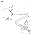
- a high-frequency surgical tool 1 of this embodiment includes: a flexible sheath 2; a control wire 3 (forward-and-backward moving section) disposed so as to freely move forward and backward inside the sheath 2; elastic grippers 7; and a controller 8.
- the sheath 2 is formed from a tube, and is capable of being inserted into the channel of an endoscope (not shown).
- the control wire 3 possesses electrical conductivity, and is a single-line wire formed so as to have the prescribed low torsional rigidity. Even twisted wire with twisted filaments is acceptable if it has the low torsional rigidity.
- the controller 8 is connected to the proximal end of the sheath 2, and controls the forward and backward movement of the control wire 3 relative to the sheath 2.
- the elastic grippers 7 have a pair of arms 5 and 6. Proximal ends of the pair of arms 5 and 6 are connected to the tip of the control wire 3 in a state in which their distal ends are deployed when they emerge from the tip of the sheath 2 in conjunction with the forward and backward movement of the control wire 3.
- the pair of arms 5 and 6 is closed by elastic deformation when they are moved into the sheath 2.
- Each of the pair of arms 5 and 6 pertaining to the elastic grippers 7 includes: a connector 10 connecting with the control wire 3; a bent portion 11; a parallel portion 12; a rectilinear portion 13; and a distal clasp 15.
- the bent portion 11 is disposed closer to the distal end than is the connector 10, and is bent at a fixed angle ⁇ in the direction of movement of the control wire 3, that is, in the direction of axis C of the sheath 2.
- the parallel portion 12 is disposed between the connector 10 and bent portion 11, and fixes the interval between the pair of arms.
- the rectilinear portion 13 maintains angle ⁇ from the bent portion 11, and linearly extends toward the distal end.
- the distal clasp 15 is disposed at the tip of the rectilinear portion 13, and strikes the diseased portion.
- bent portion 11 and parallel portion 12 of each of the pair of arms 5 and 6 are provided so as to be mutually independent, and are mutually connected to the connector 10.
- the pair of arms 5 and 6 is configured with elastic linear members that possess conductivity, and is composed from the connectors 10, parallel portions 12, rectilinear portions 13 and distal clasps 15.
- the wire diameter of the arms 5 and 6 is from 0.26 mm to 0.35 mm (shown by d in FIG. 2).
- the cross-sectional shape of the arms 5 and 6 is not limited to a circular shape, and the cross-sectional shape may be elliptical, rectangular or otherwise polygonal, so long as the circumferential length at the distal ends of the pair of arms 5 and 6 including at least the distal clasps 15 is less than or equal to 1.1 mm (shown by L in FIG. 2).
- the tips of the connectors 10 and control wire 3 are respectively inserted into a short tube 10A from both ends thereof and joined, and the periphery is covered with an adhesive 10B, whereby they are mutually fastened and connected.
- an adhesive 10B instead of the adhesive 10B, soldering or brazing material is also acceptable, and fastening by simple caulking is also acceptable.
- the length of the parallel portion 12 is 30 mm from the connector 10. This length may be in a range from 25 mm to 40 mm.
- first deployment plane S 1 first plane
- second deployment plane S2 second plane
- the rectilinear portion 13 of the arm 5 rotates in the first deployment plane S1
- the rectilinear portion 13 of the arm 6 rotates in the second deployment plane S2.
- the respective parallel portions 12 of the pair of arms 5 and 6 are arranged so as to be mutually parallel to a plane that is orthogonal to the first deployment plane S 1 and second deployment plane S2.
- the bent portions 11 are formed at an angle that enables rotation in a direction parallel to the direction of forward or backward movement of the control wire 3 by contact of the rectilinear portion 13 with the distal face 2a of the sheath 2 when the control wire 3 moves backward relative to the sheath 2.
- the rectilinear portions 13 of the pair of arms 5 and 6 are formed so as to bend in a direction in which they are respectively separated at angle ⁇ relative to the axis C.
- the angle ⁇ at this time is 40 degrees. This angle may be in a range from 35 degrees to 45 degrees.
- the rectilinear portions 13 are formed so as to extend for a length of 20 mm from the bent portions 11. The length may be in a range from 15 mm to 25 mm.
- the distal clasps 15 disposed at the tips of the rectilinear portions 13 have a length of 2.0 mm from the tip of the rectilinear portions 13, and are formed such that they are bent at an angle ⁇ of 25 degrees relative to the rectilinear portions 13 toward the inner diameter direction of the sheath 2 so as to be disposed closer to the connectors 10 than are the tips of the rectilinear portions 13.
- the length of the distal clasps 15 may be in a range from 1.5 mm to 2.5 mm, and the angle ⁇ relative to the rectilinear portions 13 may be in a range from 20 degrees to 40 degrees.
- the controller 8 includes a controller body 8A extending in the direction of the axis C of the control wire 3, and a sliding portion 8B connected to the proximal end of the control wire 3 and freely moving forward and backward relative to the controller body 8A.
- Both the controller body 8A and sliding portion 8B include finger catches 8a enabling finger application.
- the sliding portion 8B includes a connection terminal 8b for connection of the below-mentioned high-frequency power source 19 and conducting cable.
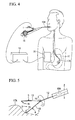
- a counter-electrode plate 18 is set up on the body surface so as to face opposite the high-frequency surgical tool 1. Furthermore, a high-frequency power source 19 (treatment energy generator) for supplying treatment energy to the pair of arms 5 and 6, the diseased portion 17A, and the counter-electrode plate 18 are respectively set up so as to form a closed loop with respect to the path of high-frequency current.
- treatment energy generator for supplying treatment energy to the pair of arms 5 and 6, the diseased portion 17A, and the counter-electrode plate 18 are respectively set up so as to form a closed loop with respect to the path of high-frequency current.
- the method of use of the high-frequency surgical tool 1 includes: a process in which the endoscope 16 is inserted into the body cavity, and the high-frequency surgical tool 1 is inserted into the channel (not shown) of the endoscope 16; a process in which the elastic grippers 7 are made to project from the distal end of the sheath 2 until the pair of arms 5 and 6 is completely deployed; a process in which the tips of the rectilinear portions 13 are pressed against the surface of the biopsy tissue 17 in the vicinity of the diseased portion 17A, and the rotational angle of each deployment plane S1 and S2 is adjusted relative to the sheath 2; a process in which the pair of arms 5,6 is closed, and the diseased portion 17A is grasped; and a process in which high-frequency current is conducted to the pair of arms 5 and 6.
- the distal end of the sheath 2 is made to project to the vicinity of the diseased portion 17A from the distal end of the insertion portion 16A of the endoscope 16.
- the sliding portion 8B of the controller 8 is withdrawn to the hand grip side which is the proximal end relative to the controller body 8A, and the elastic grippers 7 are completely stored inside the sheath 2.
- a cable (not shown) is connected to the connection terminal 8b, the entirety of the sheath 2 is moved along the channel, and the distal end of the sheath 2 is made to protrude to the vicinity of the diseased portion 17A.
- the sliding portion 8B is pushed out toward the distal end relative to the controller body 8A until the pair of arms 5 and 6 is completely deployed, and a portion of the parallel portions 12 project from the distal end of the sheath 2.
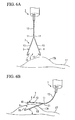
- the tip of the rectilinear portion 13 of either arm of the pair of arms 5 and 6 (in the drawing, it is the arm 6) is pressed against the biopsy tissue 17, and, using it as a fulcrum, manipulation of the torsion and curvature of the insertion portion 16A of the endoscope 16 is conducted,
- control wire 3 As the torsional rigidity of the control wire 3 is low, it is not only the parallel portion 12 that twists, but also the control wire 3.
- the elastic grippers 7 are made to rotate to the prescribed orientation, and the diseased portion 17A is inserted between the respective deployment planes S1 and S2.
- the insertion portion 16A is manipulated to a state in which the distal ends of both rectilinear portions 13 of the pair of arms 5 and 6 are pressed against the biopsy tissue 17, and the parallel portions 12 are made to bend.
- the diseased portion 17A may be inserted between the respective deployment planes S1 and S2.
- the sliding portion 8B is withdrawn to the handgrip side relative to the controller body 8A.
- the parallel portions 12 are moved into the sheath interior.
- the rectilinear portions 13 of the pair of arms 5 and 6 contact the distal face 2a of the sheath 2 in a state in which they maintain the angle ⁇ , as shown in FIG. 7A.
- the angle constituted by the tangent and axis at a desired position of the arms is continuously changed so as to gradually enlarge from the proximal end of the arms to the distal end, and is greatest at the distal end.
- the distal clasps draw closer to the sheath 2 when the control wire 3 is first moved backward toward the handgrip side, the amount of movement toward the axis C of the distal clasps is small.
- control wire 3 is then further withdrawn toward the handgrip side, and the diseased portion 17A is sandwiched between the distal clasps 15 and the distal end of the rectilinear portions 13 and the distal face 2a of the sheath 2.
- the diseased portion 17A can be removed or coagulated.
- the member that has been removed by cauterization is grasped and recovered by the distal clasps 15, and evacuated outside the body.
- the high-frequency surgical tool 1 functions as a grasping forceps.
- the diseased portion 17A can be reliably grasped by the pair of arms 5 and 6 at the desired position without slippage of the diseased portion 17A in the distal clasps 15.
- the outer circumferential length L of the distal clasps 15 is equal to or less than 1.1 mm, it is possible to raise the current density of the high-frequency current at the distal ends of the pair of arms 5 and 6, and to perform highly efficient cauterization by generating greater joule heat.
- the elastic deformation of the pair of arms 5 and 6 closed (folded) inside the sheath 2 can be generally dispersed from the bent portions 11 to the parallel portions 12 and connectors 10.
- the deployment width of the arms can be easily adjusted, and it is possible to greatly reduce any surprise of the observer at abrupt operation.
- the distal clasps 15 bend in the aforementioned manner relative to the rectilinear portions 13, with the result that the pair of arms 5 and 6 can be stored inside the sheath 2 without the distal clasps 15 catching on the distal face 2a of the sheath 2 even if they are long.
- the point of difference between the first embodiment and the second embodiment is that the inner diameter in the vicinity of the distal end of the sheath 21 of the high-frequency surgical tool 20 of this embodiment is greater than the inner diameter at its proximal end.
- the inner diameter D1 of the proximal end of the sheath 21 is 1.3 mm to 1.7 mm
- the inner diameter D2 at its distal end is 2.0 mm to 2.6 mm.
- the inner diameter D2 is approximately 1.6 times the inner diameter D1.
- the length of the distal clasps 25 from the rectilinear portions 13 on the pair of arms 22 and 23 is extended to 2.5 mm from the 2.0 mm of the first embodiment.
- the angle of bending relative to the rectilinear portions 13 is expanded from 25 degrees to 35 degrees.
- the length of the distal clasps 25 is 2.0 mm to 3.0 mm, and for the angle ⁇ relative to the rectilinear portions 13 to be in the range of 30 degrees to 50 degrees.
- the distal clasps 25 can be stored inside the sheath 21 even if the length of the distal clasps 25 are longer than in the case of the first embodiment as mentioned above.
- the point of difference between the first embodiment and the third embodiment is that the parallel portions 35 of the pair of arms 32 and 33 of the elastic grippers 31 of the high-frequency surgical tool 30 of this embodiment are curved in advance.
- the parallel portions 35 are put into a curved state so that the rectilinear portions 13 of the first embodiment rotate in parallel with the deployment planes S1 and S2 and around an axis that is orthogonal to the direction of forward or backward movement of the pair of arms 32 and 33.
- the radius of curvature R of the parallel portions 35 is, for example, 30 mm.
- the radius of curvature R may be in a range from 15 mm to 50 mm.
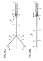
- the point of difference between the third embodiment and the fourth embodiment is that, as shown in FIG. 11, a bent portion is also provided at the distal end of the sheath 41 of the high-frequency surgical tool 40 of this embodiment.
- the radius of curvature R of the sheath 41 is a radius of curvature that is approximately identical to the radius of curvature R of the parallel portions 35 of the third embodiment.
- this high-frequency surgical tool 40 As the sheath 41 is also curved, when the sheath 41 of the high-frequency surgical tool 40 is made to project from the channel in a state in which the distal end of the insertion portion 16A is curved, it is made to project in a state in which it curves along the direction of curvature of the insertion portion 16A, under circumstances where resistance to the channel is lessened.
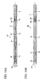
- the sheath 41 Since the sheath 41 is flexible, there is concern that the curvature shape may become deformed during transport accompanying shipment and the like.
- a pre-curved shaft-like retainer 42 may be inserted into the sheath 41 from the distal end.
- a block-shaped retainer 43 may be used to conduct pressure fixing the sheath 41 by inserting the sheath 41 into a block-shaped retainer 43.
- the block-shaped retainer 43 is curved in conformity with the radius of curvature of the sheath 41, and in which are disposed a through-hole 43 A in which are formed multiple convexities 43a that contact the inner face of the sheath 41.
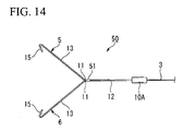
- the point of difference between the first embodiment and the fifth embodiment is that the high-frequency surgical tool 50 of this embodiment is provided with a fastener 51 which maintains the spacing of the parallel portions 12.
- the fastener 51 is arranged in the parallel portions 12 near the bent portions 11.
- FIGS. 15A to 16B Next, a sixth embodiment is described while referring to FIGS. 15A to 16B.
- the point of difference between the first embodiment and the sixth embodiment is that the connectors 10 of the pair of arms 61 and 62 of the high-frequency surgical tool 60 of this embodiment are arranged so that the rectilinear portions 13 of the arms 5 and 6 are mutually parallel in parallel planes pertaining to the first deployment plane S1 and second deployment plane S2 which rotate.
- the parallel portions 12 are in a mutual torsional relationship from the connectors 10 to the rectilinear portions 13.
- the elastic linear members of the pair of arms are in a bare state.
- an insulating cover 71 on the surface of one of the arms except for the distal clasp 15.
- an insulating coating is also acceptable.
- the torsional rigidity of the control wire 3 is reduced, and the rotatability of the elastic grippers relative to the sheath is improved, but it is also acceptable to improve the torque transmission properties of the control wire.
- the treatment tool for an endoscope is a high-frequency surgical tool, but it is not limited thereto, and it is also acceptable to have a two-arm grasping forceps that do not have the functions of high-frequency surgery.
- surgery time was measured when gastric mucosa (a fold with a width of approximately 5 mm) was grasped, and cut with conduction of high-frequency current at 60 W of power source output.
- Table 1 Outer circumferential length (mm) of distal clasps Surgery time (seconds) 1.26 (inoperable due to the large amount of time and display of an error message) 1.1 5 to 8 1.0 4 to 8 0.9 4 to 5 0.8 3 to 4
- the desired cutting quality is obtainable with a surgery time equal to or less than 8 seconds.
Landscapes
- Health & Medical Sciences (AREA)
- Surgery (AREA)
- Engineering & Computer Science (AREA)
- Life Sciences & Earth Sciences (AREA)
- Biomedical Technology (AREA)
- Molecular Biology (AREA)
- Nuclear Medicine, Radiotherapy & Molecular Imaging (AREA)
- Plasma & Fusion (AREA)
- Physics & Mathematics (AREA)
- Heart & Thoracic Surgery (AREA)
- Medical Informatics (AREA)
- Otolaryngology (AREA)
- Animal Behavior & Ethology (AREA)
- General Health & Medical Sciences (AREA)
- Public Health (AREA)
- Veterinary Medicine (AREA)
- Surgical Instruments (AREA)
- Endoscopes (AREA)
Applications Claiming Priority (1)
| Application Number | Priority Date | Filing Date | Title |
|---|---|---|---|
| JP2005313659A JP4137931B2 (ja) | 2005-10-28 | 2005-10-28 | 内視鏡用処置具 |
Publications (3)
| Publication Number | Publication Date |
|---|---|
| EP1782742A2 true EP1782742A2 (fr) | 2007-05-09 |
| EP1782742A3 EP1782742A3 (fr) | 2007-05-30 |
| EP1782742B1 EP1782742B1 (fr) | 2010-02-17 |
Family
ID=37890181
Family Applications (1)
| Application Number | Title | Priority Date | Filing Date |
|---|---|---|---|
| EP06022407A Active EP1782742B1 (fr) | 2005-10-28 | 2006-10-26 | Outil de traitment pour un endoscope |
Country Status (4)
| Country | Link |
|---|---|
| US (1) | US7824407B2 (fr) |
| EP (1) | EP1782742B1 (fr) |
| JP (1) | JP4137931B2 (fr) |
| DE (1) | DE602006012262D1 (fr) |
Cited By (2)
| Publication number | Priority date | Publication date | Assignee | Title |
|---|---|---|---|---|
| EP2022430A1 (fr) | 2007-07-25 | 2009-02-11 | SRJ Corporation | Outil de traitement endoscopique |
| CN105358036A (zh) * | 2013-06-28 | 2016-02-24 | 奥林巴斯株式会社 | 内窥镜系统 |
Families Citing this family (14)
| Publication number | Priority date | Publication date | Assignee | Title |
|---|---|---|---|---|
| EP2012695B1 (fr) * | 2006-03-31 | 2015-07-22 | Cook Medical Technologies LLC | Instrument de coupe électro-chirurgical |
| JP5098024B2 (ja) * | 2007-11-07 | 2012-12-12 | 有限会社リバー精工 | 内視鏡用高周波処置具 |
| EP2552327B1 (fr) * | 2010-03-29 | 2017-08-09 | Cook Medical Technologies LLC | Dispositif de positionnement de structure implantée pour faciliter son enlèvement |
| US8942530B2 (en) | 2011-09-20 | 2015-01-27 | San Marino Capital, Inc. | Endoscope connector method and apparatus |
| JP6095507B2 (ja) | 2013-06-28 | 2017-03-15 | オリンパス株式会社 | 内視鏡システム |
| CN105338879B (zh) | 2013-06-28 | 2017-12-19 | 奥林巴斯株式会社 | 内窥镜系统 |
| JP6177095B2 (ja) | 2013-11-08 | 2017-08-09 | オリンパス株式会社 | 処置具及び医用システム |
| US9687294B2 (en) * | 2014-11-17 | 2017-06-27 | Covidien Lp | Deployment mechanism for surgical instruments |
| EP3226782B1 (fr) * | 2014-12-02 | 2020-06-03 | Merit Medical Systems, Inc. | Dispositif de préhension médical |
| CN107072671B (zh) * | 2015-05-27 | 2019-08-30 | 奥林巴斯株式会社 | 内窥镜用处置器具 |
| WO2017210190A1 (fr) * | 2016-06-02 | 2017-12-07 | Merit Medical Systems, Inc. | Dispositif de préhension médical |
| US10610234B2 (en) * | 2016-11-15 | 2020-04-07 | Zhejiang Chuangxiang Medical Technology Co., Ltd. | Open-close-repeatable rotatable hemoclip for the gastrointestinal tract with electrocoagulation |
| CN112955081A (zh) * | 2018-10-22 | 2021-06-11 | 奥林巴斯株式会社 | 内窥镜夹具 |
| US10710247B2 (en) * | 2018-11-08 | 2020-07-14 | Sri International | Gripper devices |
Citations (2)
| Publication number | Priority date | Publication date | Assignee | Title |
|---|---|---|---|---|
| JPH0511913A (ja) | 1991-06-28 | 1993-01-22 | Shimadzu Corp | 表示装置用キーボード |
| JPH0542167A (ja) | 1991-08-16 | 1993-02-23 | Olympus Optical Co Ltd | 内視鏡用高周波処置具 |
Family Cites Families (12)
| Publication number | Priority date | Publication date | Assignee | Title |
|---|---|---|---|---|
| US2137710A (en) * | 1937-12-13 | 1938-11-22 | Alfred W Anderson | Forceps |
| JPS5320957Y2 (fr) | 1973-11-14 | 1978-06-01 | ||
| DE2513868C2 (de) * | 1974-04-01 | 1982-11-04 | Olympus Optical Co., Ltd., Tokyo | Bipolare Elektrodiathermiefaßzange |
| JPS6028408A (ja) | 1983-07-27 | 1985-02-13 | Mitsui Toatsu Chem Inc | ポリ−α−メチルスチレンの製造方法 |
| US5542432A (en) * | 1992-02-18 | 1996-08-06 | Symbiosis Corporation | Endoscopic multiple sample bioptome |
| CA2106126A1 (fr) * | 1992-09-23 | 1994-03-24 | Ian M. Scott | Instruments chirurgicaux bipolaires |
| JPH08299349A (ja) | 1995-05-12 | 1996-11-19 | Olympus Optical Co Ltd | 内視鏡用処置具 |
| US5797957A (en) * | 1996-05-02 | 1998-08-25 | Symbiosis Corporation | Endoscopic bioptome with a hard stop to control biting force |
| JP4166414B2 (ja) * | 2000-05-17 | 2008-10-15 | オリンパス株式会社 | 内視鏡用処置具 |
| JP3989170B2 (ja) * | 2000-10-05 | 2007-10-10 | オリンパス株式会社 | 高周波処置具 |
| US6679893B1 (en) * | 2000-11-16 | 2004-01-20 | Chestnut Medical Technologies, Inc. | Grasping device and method of use |
| WO2004006789A1 (fr) | 2002-07-12 | 2004-01-22 | Cook Urological, Incorporated | Arbre flexible de canule |
-
2005
- 2005-10-28 JP JP2005313659A patent/JP4137931B2/ja not_active Expired - Fee Related
-
2006
- 2006-10-26 US US11/553,084 patent/US7824407B2/en active Active
- 2006-10-26 EP EP06022407A patent/EP1782742B1/fr active Active
- 2006-10-26 DE DE602006012262T patent/DE602006012262D1/de active Active
Patent Citations (2)
| Publication number | Priority date | Publication date | Assignee | Title |
|---|---|---|---|---|
| JPH0511913A (ja) | 1991-06-28 | 1993-01-22 | Shimadzu Corp | 表示装置用キーボード |
| JPH0542167A (ja) | 1991-08-16 | 1993-02-23 | Olympus Optical Co Ltd | 内視鏡用高周波処置具 |
Cited By (6)
| Publication number | Priority date | Publication date | Assignee | Title |
|---|---|---|---|---|
| EP2022430A1 (fr) | 2007-07-25 | 2009-02-11 | SRJ Corporation | Outil de traitement endoscopique |
| US7691104B2 (en) | 2007-07-25 | 2010-04-06 | Olympus Medical Systems Corporation | Endoscopic treatment tool |
| CN105358036A (zh) * | 2013-06-28 | 2016-02-24 | 奥林巴斯株式会社 | 内窥镜系统 |
| EP3015050A4 (fr) * | 2013-06-28 | 2017-03-08 | Olympus Corporation | Système d'endoscopie |
| CN105358036B (zh) * | 2013-06-28 | 2017-09-19 | 奥林巴斯株式会社 | 内窥镜系统 |
| US10016235B2 (en) | 2013-06-28 | 2018-07-10 | Olympus Corporation | Endoscope system having first transmission and reception electrodes, second transmission and reception electrodes and electrically powered treatment device powered to perform treatment |
Also Published As
| Publication number | Publication date |
|---|---|
| EP1782742A3 (fr) | 2007-05-30 |
| US7824407B2 (en) | 2010-11-02 |
| US20070135813A1 (en) | 2007-06-14 |
| DE602006012262D1 (de) | 2010-04-01 |
| EP1782742B1 (fr) | 2010-02-17 |
| JP2007117405A (ja) | 2007-05-17 |
| JP4137931B2 (ja) | 2008-08-20 |
Similar Documents
| Publication | Publication Date | Title |
|---|---|---|
| EP1782742B1 (fr) | Outil de traitment pour un endoscope | |
| US10870143B2 (en) | Connection structure and connection method | |
| JP4546424B2 (ja) | 内視鏡用処置具 | |
| CN108938048B (zh) | 腹腔镜夹钳组件 | |
| US9510824B2 (en) | Low profile medical device and related methods of use | |
| US6162239A (en) | Instrument with independent pliers | |
| JP5244804B2 (ja) | 筒状の軸機器 | |
| CN102727283B (zh) | 外科钳及其制造方法 | |
| KR101896053B1 (ko) | 양극 소작 기구 | |
| US20190150966A1 (en) | Magnetic introducer systems and methods | |
| US20130238016A1 (en) | Articulating Surgical Apparatus | |
| US7008420B2 (en) | High frequency surgical instrument | |
| US11911020B2 (en) | Needle holder for endoscope, suture set, and suture system | |
| WO2016147471A1 (fr) | Instrument de traitement | |
| US20200008829A1 (en) | Electrosurgical forceps with resilient jaws | |
| JPH0542167A (ja) | 内視鏡用高周波処置具 | |
| JP2010142279A (ja) | 処置具 | |
| US8647362B2 (en) | Device with deflectable distal end and related methods of use | |
| US7404817B2 (en) | High-frequency incision device | |
| KR102076622B1 (ko) | 착탈식 의료용 스네어 전류 연결기구 및 이를 이용한 의료용 스네어 | |
| CN109893239B (zh) | 便于组织移除的基于能量的外科装置和系统 | |
| US20140221986A1 (en) | Multi-functional medical device and related methods of use | |
| US20240148397A1 (en) | End tool of surgical instrument, and electrocauterization surgical instrument comprising same | |
| JPH07310U (ja) | 内視鏡用高周波ナイフ |
Legal Events
| Date | Code | Title | Description |
|---|---|---|---|
| PUAI | Public reference made under article 153(3) epc to a published international application that has entered the european phase |
Free format text: ORIGINAL CODE: 0009012 |
|
| PUAL | Search report despatched |
Free format text: ORIGINAL CODE: 0009013 |
|
| AK | Designated contracting states |
Kind code of ref document: A2 Designated state(s): AT BE BG CH CY CZ DE DK EE ES FI FR GB GR HU IE IS IT LI LT LU LV MC NL PL PT RO SE SI SK TR |
|
| AX | Request for extension of the european patent |
Extension state: AL BA HR MK YU |
|
| AK | Designated contracting states |
Kind code of ref document: A3 Designated state(s): AT BE BG CH CY CZ DE DK EE ES FI FR GB GR HU IE IS IT LI LT LU LV MC NL PL PT RO SE SI SK TR |
|
| AX | Request for extension of the european patent |
Extension state: AL BA HR MK YU |
|
| 17P | Request for examination filed |
Effective date: 20070810 |
|
| 17Q | First examination report despatched |
Effective date: 20071004 |
|
| AKX | Designation fees paid |
Designated state(s): DE FR GB IE |
|
| GRAP | Despatch of communication of intention to grant a patent |
Free format text: ORIGINAL CODE: EPIDOSNIGR1 |
|
| GRAS | Grant fee paid |
Free format text: ORIGINAL CODE: EPIDOSNIGR3 |
|
| RIN1 | Information on inventor provided before grant (corrected) |
Inventor name: KIMURA, MEGUMI Inventor name: TAKAHASHI, ICHIRO Inventor name: YAMAMOTO, HIRONORI |
|
| GRAA | (expected) grant |
Free format text: ORIGINAL CODE: 0009210 |
|
| AK | Designated contracting states |
Kind code of ref document: B1 Designated state(s): DE FR GB IE |
|
| REG | Reference to a national code |
Ref country code: GB Ref legal event code: FG4D |
|
| REG | Reference to a national code |
Ref country code: IE Ref legal event code: FG4D |
|
| REF | Corresponds to: |
Ref document number: 602006012262 Country of ref document: DE Date of ref document: 20100401 Kind code of ref document: P |
|
| PLBE | No opposition filed within time limit |
Free format text: ORIGINAL CODE: 0009261 |
|
| STAA | Information on the status of an ep patent application or granted ep patent |
Free format text: STATUS: NO OPPOSITION FILED WITHIN TIME LIMIT |
|
| 26N | No opposition filed |
Effective date: 20101118 |
|
| REG | Reference to a national code |
Ref country code: FR Ref legal event code: PLFP Year of fee payment: 10 |
|
| REG | Reference to a national code |
Ref country code: GB Ref legal event code: 732E Free format text: REGISTERED BETWEEN 20150827 AND 20150902 |
|
| REG | Reference to a national code |
Ref country code: DE Ref legal event code: R082 Ref document number: 602006012262 Country of ref document: DE Representative=s name: WUESTHOFF & WUESTHOFF, PATENTANWAELTE PARTG MB, DE Ref country code: DE Ref legal event code: R081 Ref document number: 602006012262 Country of ref document: DE Owner name: OLYMPUS CORPORATION, JP Free format text: FORMER OWNER: OLYMPUS MEDICAL SYSTEMS CORP., TOKIO/TOKYO, JP |
|
| REG | Reference to a national code |
Ref country code: FR Ref legal event code: TP Owner name: OLYMPUS CORPORATION, JP Effective date: 20160205 |
|
| REG | Reference to a national code |
Ref country code: FR Ref legal event code: PLFP Year of fee payment: 11 |
|
| REG | Reference to a national code |
Ref country code: FR Ref legal event code: CA Effective date: 20161108 |
|
| REG | Reference to a national code |
Ref country code: FR Ref legal event code: PLFP Year of fee payment: 12 |
|
| REG | Reference to a national code |
Ref country code: FR Ref legal event code: PLFP Year of fee payment: 13 |
|
| PGFP | Annual fee paid to national office [announced via postgrant information from national office to epo] |
Ref country code: FR Payment date: 20221028 Year of fee payment: 17 |
|
| PGFP | Annual fee paid to national office [announced via postgrant information from national office to epo] |
Ref country code: IE Payment date: 20221020 Year of fee payment: 17 Ref country code: GB Payment date: 20221019 Year of fee payment: 17 |
|
| P01 | Opt-out of the competence of the unified patent court (upc) registered |
Effective date: 20230528 |
|
| PGFP | Annual fee paid to national office [announced via postgrant information from national office to epo] |
Ref country code: DE Payment date: 20231020 Year of fee payment: 18 |