EP1780925A2 - Système de communication à antennes multiples utilisant un précodeur spatial - Google Patents
Système de communication à antennes multiples utilisant un précodeur spatial Download PDFInfo
- Publication number
- EP1780925A2 EP1780925A2 EP06022705A EP06022705A EP1780925A2 EP 1780925 A2 EP1780925 A2 EP 1780925A2 EP 06022705 A EP06022705 A EP 06022705A EP 06022705 A EP06022705 A EP 06022705A EP 1780925 A2 EP1780925 A2 EP 1780925A2
- Authority
- EP
- European Patent Office
- Prior art keywords
- coding
- streams
- data
- space pre
- antennas
- Prior art date
- Legal status (The legal status is an assumption and is not a legal conclusion. Google has not performed a legal analysis and makes no representation as to the accuracy of the status listed.)
- Granted
Links
Images


Classifications
-
- H—ELECTRICITY
- H04—ELECTRIC COMMUNICATION TECHNIQUE
- H04B—TRANSMISSION
- H04B7/00—Radio transmission systems, i.e. using radiation field
- H04B7/02—Diversity systems; Multi-antenna system, i.e. transmission or reception using multiple antennas
-
- H—ELECTRICITY
- H04—ELECTRIC COMMUNICATION TECHNIQUE
- H04L—TRANSMISSION OF DIGITAL INFORMATION, e.g. TELEGRAPHIC COMMUNICATION
- H04L27/00—Modulated-carrier systems
- H04L27/26—Systems using multi-frequency codes
- H04L27/2601—Multicarrier modulation systems
-
- H—ELECTRICITY
- H04—ELECTRIC COMMUNICATION TECHNIQUE
- H04B—TRANSMISSION
- H04B7/00—Radio transmission systems, i.e. using radiation field
- H04B7/02—Diversity systems; Multi-antenna system, i.e. transmission or reception using multiple antennas
- H04B7/04—Diversity systems; Multi-antenna system, i.e. transmission or reception using multiple antennas using two or more spaced independent antennas
- H04B7/0408—Diversity systems; Multi-antenna system, i.e. transmission or reception using multiple antennas using two or more spaced independent antennas using two or more beams, i.e. beam diversity
-
- H—ELECTRICITY
- H04—ELECTRIC COMMUNICATION TECHNIQUE
- H04B—TRANSMISSION
- H04B7/00—Radio transmission systems, i.e. using radiation field
- H04B7/02—Diversity systems; Multi-antenna system, i.e. transmission or reception using multiple antennas
- H04B7/04—Diversity systems; Multi-antenna system, i.e. transmission or reception using multiple antennas using two or more spaced independent antennas
- H04B7/06—Diversity systems; Multi-antenna system, i.e. transmission or reception using multiple antennas using two or more spaced independent antennas at the transmitting station
- H04B7/0686—Hybrid systems, i.e. switching and simultaneous transmission
- H04B7/0691—Hybrid systems, i.e. switching and simultaneous transmission using subgroups of transmit antennas
-
- H—ELECTRICITY
- H04—ELECTRIC COMMUNICATION TECHNIQUE
- H04L—TRANSMISSION OF DIGITAL INFORMATION, e.g. TELEGRAPHIC COMMUNICATION
- H04L1/00—Arrangements for detecting or preventing errors in the information received
- H04L1/0001—Systems modifying transmission characteristics according to link quality, e.g. power backoff
- H04L1/0002—Systems modifying transmission characteristics according to link quality, e.g. power backoff by adapting the transmission rate
- H04L1/0003—Systems modifying transmission characteristics according to link quality, e.g. power backoff by adapting the transmission rate by switching between different modulation schemes
-
- H—ELECTRICITY
- H04—ELECTRIC COMMUNICATION TECHNIQUE
- H04L—TRANSMISSION OF DIGITAL INFORMATION, e.g. TELEGRAPHIC COMMUNICATION
- H04L1/00—Arrangements for detecting or preventing errors in the information received
- H04L1/0001—Systems modifying transmission characteristics according to link quality, e.g. power backoff
- H04L1/0009—Systems modifying transmission characteristics according to link quality, e.g. power backoff by adapting the channel coding
-
- H—ELECTRICITY
- H04—ELECTRIC COMMUNICATION TECHNIQUE
- H04L—TRANSMISSION OF DIGITAL INFORMATION, e.g. TELEGRAPHIC COMMUNICATION
- H04L1/00—Arrangements for detecting or preventing errors in the information received
- H04L1/02—Arrangements for detecting or preventing errors in the information received by diversity reception
- H04L1/06—Arrangements for detecting or preventing errors in the information received by diversity reception using space diversity
- H04L1/0606—Space-frequency coding
-
- H—ELECTRICITY
- H04—ELECTRIC COMMUNICATION TECHNIQUE
- H04L—TRANSMISSION OF DIGITAL INFORMATION, e.g. TELEGRAPHIC COMMUNICATION
- H04L1/00—Arrangements for detecting or preventing errors in the information received
- H04L1/02—Arrangements for detecting or preventing errors in the information received by diversity reception
- H04L1/06—Arrangements for detecting or preventing errors in the information received by diversity reception using space diversity
- H04L1/0618—Space-time coding
- H04L1/0675—Space-time coding characterised by the signaling
-
- H—ELECTRICITY
- H04—ELECTRIC COMMUNICATION TECHNIQUE
- H04B—TRANSMISSION
- H04B7/00—Radio transmission systems, i.e. using radiation field
- H04B7/02—Diversity systems; Multi-antenna system, i.e. transmission or reception using multiple antennas
- H04B7/04—Diversity systems; Multi-antenna system, i.e. transmission or reception using multiple antennas using two or more spaced independent antennas
- H04B7/06—Diversity systems; Multi-antenna system, i.e. transmission or reception using multiple antennas using two or more spaced independent antennas at the transmitting station
- H04B7/0613—Diversity systems; Multi-antenna system, i.e. transmission or reception using multiple antennas using two or more spaced independent antennas at the transmitting station using simultaneous transmission
- H04B7/0667—Diversity systems; Multi-antenna system, i.e. transmission or reception using multiple antennas using two or more spaced independent antennas at the transmitting station using simultaneous transmission of delayed versions of same signal
- H04B7/0669—Diversity systems; Multi-antenna system, i.e. transmission or reception using multiple antennas using two or more spaced independent antennas at the transmitting station using simultaneous transmission of delayed versions of same signal using different channel coding between antennas
-
- H—ELECTRICITY
- H04—ELECTRIC COMMUNICATION TECHNIQUE
- H04B—TRANSMISSION
- H04B7/00—Radio transmission systems, i.e. using radiation field
- H04B7/02—Diversity systems; Multi-antenna system, i.e. transmission or reception using multiple antennas
- H04B7/04—Diversity systems; Multi-antenna system, i.e. transmission or reception using multiple antennas using two or more spaced independent antennas
- H04B7/06—Diversity systems; Multi-antenna system, i.e. transmission or reception using multiple antennas using two or more spaced independent antennas at the transmitting station
- H04B7/0613—Diversity systems; Multi-antenna system, i.e. transmission or reception using multiple antennas using two or more spaced independent antennas at the transmitting station using simultaneous transmission
- H04B7/068—Diversity systems; Multi-antenna system, i.e. transmission or reception using multiple antennas using two or more spaced independent antennas at the transmitting station using simultaneous transmission using space frequency diversity
-
- H—ELECTRICITY
- H04—ELECTRIC COMMUNICATION TECHNIQUE
- H04L—TRANSMISSION OF DIGITAL INFORMATION, e.g. TELEGRAPHIC COMMUNICATION
- H04L1/00—Arrangements for detecting or preventing errors in the information received
- H04L1/02—Arrangements for detecting or preventing errors in the information received by diversity reception
- H04L1/06—Arrangements for detecting or preventing errors in the information received by diversity reception using space diversity
- H04L1/0618—Space-time coding
Definitions
- the present invention relates generally to an apparatus and method for transmitting/receiving data in a communication system using multiple antennas (hereinafter referred to as a "multi-antenna communication system"), and in particular, to an apparatus and method for spatial multiplexing transmission in a multi-antenna communication system.
- a wireless communication system has been developed to allow users to perform communication without distance limitations.
- a mobile communication system is the typical wireless communication system.
- the mobile communication system has evolved from the early voice service communication system into a high-speed, high-quality wireless packet data communication system for providing data service and multimedia service.
- HSDPA High Speed Downlink Packet Access
- 3GPP 3 rd Generation Partnership Project
- EV-DV Evolution for Data and Voice
- EV-DO Evolution-Data Only
- the current 3G wireless packet data communication systems like the HSDPA, EV-DV and EV-DO, use an Adaptive Modulation and Coding (AMC) method and a channel sensitive scheduling resource management method to improve transmission efficiency.
- AMC Adaptive Modulation and Coding
- a transmitter can adjust the amount of transmission data according to channel status. That is, the transmitter decreases the amount of transmission data in a channel having bad status and increases the amount of transmission data in a channel having good status, thereby efficiently transmitting the large amount of data while maintaining a desired reception error probability.
- a transmitter selects a good-channel status user, thereby increasing the data throughput.
- the transmitter receives partial channel status information fed back from a receiver, and applies an appropriate modulation and coding technique determined at the time to be most efficient.
- the channel status information fed back by the receiver should be matched to the channel status at the transmission time.
- the channel status changes continuously.
- the continuous change in the channel status is related to moving velocity of the transmitter or the receiver, and this is called Doppler spread. High moving velocity deepens the Doppler spread. In this case, the channel status information fed back by the receiver may be invalid.
- the 3G wireless packet data communication system adopts Hybrid Automatic ReQuest (HARQ).
- HARQ Hybrid Automatic ReQuest
- the HARQ technology when a receiver fails to normally receive the data transmitted by a transmitter, the receiver immediately informs the transmitter of the failure so that the transmitter rapidly performs retransmission in a physical layer.
- an OFDMA scheme is a method for sending different user signals on different sub-carriers based on the OFDM scheme.
- channel sensitive scheduling which could be performed only in the time axis can be performed even in the frequency axis. That is, for data transmission, the OFDMA system schedules a sub-carrier preferred by each user in the frequency selective fading environment through frequency scheduling, thereby improving the system capacity as compared with the case where scheduling is performed only in the time axis. Therefore, in order to efficiently perform frequency scheduling, it is preferable to use a bundle of adjacent sub-carriers having a similar channel response for data transmission taking into account of overhead of the channel status feedback.
- MIMO Multiple-Input Multiple-Output
- SDM Spatial Domain Multiplexing
- the Spatial Diversity technique is developed to prevent a reduction in link performance due to fading occurring in a mobile communication channel by using multiple transmission/reception antennas.
- the Spatial Diversity technique can efficiently reduce a reception error probability, when a transmitter has channel status information and cannot adaptively adjust the amount of transmission information.
- the SDM technique is developed to transmit the larger amount of data using the MIMO scheme, as compared with the single-transmission/reception antenna technique.
- the SDM technique can efficiently increase data throughput in an environment where the spatial correlation is very low due to the scattering objects having a sufficient number of channel environments.
- the SDM technique extended based on multiple access is a Spatial Domain Multiple Access (SDMA) technique.
- SDMA Spatial Domain Multiple Access
- the SDM technique increases the number of transmission channels over which data is transmitted, using multiple transmission/reception antennas.
- the spatial correlation is low, it is possible to increase the data throughput using the SDM technique.
- the spatial correlation is high, even though the data throughput is increased, it is not possible to prevent an increase in the reception error probability.
- transmission channels over which the data (the amount of which is increased with the use of the MIMO scheme) is transmitted are allocated to different users, it helps increase the system capacity. This is because if the spatial correlation is high, interference between user signals having different spatial characteristics may decrease. That is, the SDMA technique is a spatial processing technique capable of increasing the system capacity in the high-spatial correlation environment.
- Each of such spatial processing techniques as Spatial Diversity technique, SDM technique and SDMA technique differs in available scope according to traffic type and channel environment showing capacity improvement. For example, for a voice call, because similar amounts of data are always generated, it is difficult to apply the AMC method and the channel sensitive scheduling resource management method, both of which vary the data throughput. In addition, if the channel status becomes bad due to fading, a reception error is unavoidable. In this situation, the use of the Spatial Diversity technique can prevent the channel status from deteriorating. In the channel environment where the spatial correlation is low, the use of the SDM technique can increase the data throughput, together with the AMC method and the channel sensitive scheduling resource management method. In the channel environment where the spatial correlation is high, the SDMA technique can improve the system capacity. Therefore, there is a need to appropriately select the spatial processing technique according to the channel environment and traffic type.
- FIG. 1 is a diagram illustrating a structure of a transmitter in a wireless communication system employing Space-Time Coding (STC).
- STC Space-Time Coding
- the AMC unit 100 includes therein a channel coding/modulation unit 110 and an AMC controller 101.
- the channel coding/modulation unit 110 includes therein a channel encoder 111, a channel interleaver 112, and a modulator 113. Therefore, the data 10 is input to the channel encoder 111.
- the data coded by the channel encoder 111 is dispersed (or permutated) by the channel interleaver 112. The reason for dispersing the data by the channel interleaver 112 is to prevent deterioration of coding performance due to fading during data transmission.
- the data dispersed by the channel interleaver 112 is converted into a modulation signal by the modulator 113.
- a series of processes where the data undergoes coding 111, interleaving 112, and modulation 113 is called a "channel coding and modulation" process. Therefore, this process is performed in the channel coding/modulation unit 110.
- the channel coding/modulation unit 110 can apply a different scheme depending on Channel Status Information (CSI) feedback 105 that a receiver has delivered according to the system. For example, if the channel status is good, the channel coding/modulation unit 110 increases a channel coding rate and a modulation order so that the increased amount of data is transmitted. However, if the channel status is bad, the channel coding/modulation unit 110 decreases the coding rate and the modulation order so that the decreased amount of data is transmitted more reliably. In this way, the transmitter applies AMC based on the CSI feedback 105, and the AMC controller 101 determines which coding and modulation schemes it will use. The AMC controller may be omitted, according to the particular design. That is, it is meant in FIG.
- CSI Channel Status Information
- AMC process A process in which the AMC controller 101 adaptively changes the channel coding and modulation schemes based on the CSI feedback 105 is called an AMC process. Therefore, an apparatus provided for performing the AMC process is shown as an AMC unit 100 in FIG. 1.
- the signal modulated by the AMC unit 100 is STC-coded by an STC encoder 121.
- the STC encoder 121 typically adopts an Alamouti coding method, which is applied to two transmission antennas.
- the Alamouti coding method which corresponds to Orthogonal Space Time Coding (OSTC), can obtain the maximum diversity gain.
- OFSC Orthogonal Space Time Coding
- the Alamouti coding method there should be no change in the channel between Alamouti-coded adjacent time signals in order to maintain orthogonality. If the channel between the adjacent time signals undergoes an abrupt change, the Alamouti coding method cannot guarantee orthogonality, causing self-interference and performance deterioration due thereto.
- the OSTC coding method guaranteeing orthogonality provides the maximum diversity gain.
- the general STC coding method is performed without depending on the CSI that the receiver feeds back. Therefore, the STC coding method is designed to maximize the diversity gain, rather than being modified to be adaptive to the channel.
- the signal obtained by STC-coding the modulation signal is converted into a transmission band signal by a Radio Frequency (RF) unit 122, generating a plurality of symbols to be transmitted via multiple transmission antennas 131 through 132.
- RF Radio Frequency
- the STC coding method applied to a 2-transmission antenna system receives one data stream and outputs two symbol streams. The generated symbol streams are transmitted via different transmission antennas 131 and 132.
- the symbol stream to which the STC coding method is applied is converted by the RF unit 122 into an RF signal to be transmitted via a transmission antenna.
- the RF unit 122 performs filtering for satisfying a spectrum characteristic, adjusts transmission power, and converts a baseband signal into an RF signal. After this process, the output signals are transmitted via their associated antennas 131 and 132.
- FIG. 2 is a diagram illustrating a structure of a transmitter employing OFDM-STC coding.
- FIG. 2 a description will now be made of a structure and operation of a transmitter employing OFDM-STC coding.
- An AMC unit 100 is equal to that of FIG. 1 in operation, so a description thereof is omitted here.
- the signal modulated by the AMC unit 100 is input to an OFDM modulator 210.
- the OFDM modulator 210 includes therein an Inverse Fast Fourier Transform (IFFT) unit 211 and a Cyclic Prefix (CP) symbol adder 212. Therefore, the signal modulated by the AMC unit 100 is input to the IFFT unit 211.
- the IFFT unit 211 performs IFFT on the modulation signal such that the modulated signals should be carried on orthogonal frequency signals, that is, sub-carriers. Thereafter, a CP symbol is added to the IFFT-processed signal by the CP symbol adder 212.
- the CP is achieved by copying a part of the last part of a generated sub-carrier and adding the copied part to the head of the symbol, to maintain the orthogonality between sub-carriers even though delay spread occurs due to multi-path fading, thereby preventing interference.
- an STC encoder 121 performs STC coding on consecutive OFDM symbols.
- an RF unit 122 converts the STC-coded OFDM symbols into transmission band RF signals, and then transmits the RF signals via multiple transmission antennas 131 and 132.
- the orthogonality may be affected, causing interference.
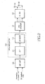
- FIG. 3 is a block diagram illustrating a structure of a transmitter employing OFDM-SFC coding. A description will now be made of a structure and operation of a transmitter employing OFDM-SFC (Space Frequency Coding) coding.
- OFDM-SFC Space Frequency Coding
- an SFC coding method can be implemented by applying the STC coding method to consecutive frequency signals, that is, sub-carriers, instead of applying the STC coding method to consecutive time signals.
- An AMC unit 100 outputs a modulated signal using an input information bit stream 10 and SCI feedback information 105.
- the output modulation signal is input to an SFC encoder 300.
- the SFC encoder 300 performs the same process as the STC coding process, but finally applies STC coding to the consecutive frequency signals, so this coding method is called an SFC coding method.
- the signal stream modulated by the SFC encoder 300 is obtained by applying STC coding to consecutive time signals.
- One stream is coded into a plurality of streams by the SFC encoder 300, and the streams are separately modulated by ODFM modulators 210a to 210n.
- the STC-coded signals are converted into OFDM signals by the OFDM modulators 210a to 210n. It can be considered herein that the STC coding applied to the consecutive time signals by the OFDM modulators 210a to 210n are applied to consecutive frequency signals. Thereafter, the OFDM signals are converted into transmission signals by an RF unit 122, and then transmitted via associated transmission antennas 131 and 132.
- the orthogonality may be affected, causing interference.
- FIGs. 2 and 3 respectively show a transmission scheme employing STC coding, and a transmission scheme employing SFC coding that implements STC coding in the frequency axis.
- Such conventional techniques were designed to obtain the maximum spatial diversity gain, as described above. Therefore, such techniques show excellent link performance in the low-spatial correlation environment, but cannot provide a multi-antenna gain if the spatial correlation increases.
- the reason for showing the excellent link performance in the low-spatial correlation environment is because the use of the diversity technique, like other kinds of diversity techniques, can reduce the change in channel with the passage of time.
- the diversity technique helps reduce the probability of channel deterioration by reducing the change in the channel, but reduces a large number of channels capable of transmitting data. For this reason, it is known that in the system supporting AMC and channel sensitive scheduling, the diversity technique reduces the system capacity undesirably.
- FIG. 4 is a block diagram illustrating a structure of a transmitter employing OFDM-based spatial multiplexing. With reference to FIG. 4, a description will now be made of a structure and operation of a transmitter employing OFDM-based spatial multiplexing.
- the STC coding technique and the SFC coding technique transmit one data stream, whereas the spatial multiplexing technique transmits a plurality of data streams.
- a predetermined number of data streams can be transmitted, wherein the predetermined number corresponds to a smaller one from among the number of transmission antennas and the number of reception antennas.
- the receiver also needs more than M antennas.
- the STC coding technique and the SFC coding scheme transmit only one data stream, they do not need a plurality of reception antennas.
- the spatial multiplexing technique uses such characteristics of the MIMO system.
- transmission data streams are individually input to AMC units 100a to 100n where they undergo an AMC process independently. Thereafter, the resulting streams are OFDM-modulated by OFDM modulators 210a to 210n.
- the OFDM-modulated symbols are converted into RF transmission signals by an RF unit 122, and then transmitted to a receiver via multiple transmission antennas 131 and 132. That is, different data streams are transmitted via different transmission antennas.
- the AMC units 100a to 100n shown in FIG. 4 can be used when the system performs CSI feedback. If the CSI is not fed back, the fixed coding and modulation schemes are performed. In this case, the AMC units 100a to 100n perform the fixed coding and modulation schemes.
- a first method applies the same AMC method for all transmission antennas.
- a receiver is allowed to feed back only one representative CSI.
- a second method applies different AMC methods for all transmission antennas.
- the receiver should feed back a CSI corresponding to each of the transmission antennas. That is, the former method is less than the latter method in terms of the CSI feedback overhead.
- FIG. 4 shows the latter method that allows the receiver to feed back a CSI for each of the transmission antennas, and shows the transmitter employing an AMC method according thereto.
- PARC Per Antenna Rate Control
- FIG. 5 is a block diagram illustrating a structure of a transmitter employing PARC in a system supporting AMC and channel sensitive scheduling. With reference to FIG. 5, a description will now be made of a structure and operation of a transmitter employing PARC in a system supporting AMC and channel sensitive scheduling.
- a scheduler 501 receives transmission data 10a to 10n of K multiple users from an upper layer.
- the scheduler 501 is a channel sensitive scheduler (hereinafter referred to as "scheduler" for simplicity).
- the scheduler 501 selects the most preferred user terminal to which it will transmit data at the present time, based on the CSI fed back from each user terminal.
- the scheduler 501 provides scheduling information 510 to an AMC controller 505.
- the AMC controller 505 analyzes the scheduled user and issues an AMC command according to a channel status of the user.
- the scheduler 501 generates the information indicating via which antenna and with which coding and modulation methods it will transmit transmission data, and provides the generated information to the AMC controller 505. Therefore, the AMC controller 505 can determine the number of transmission data streams and a size of the transmission data for each individual antenna, based on the information on the transmission antennas.
- a multiplexer 503 multiplexes user information bit stream scheduled by the scheduler 501 according to the number of transmission antennas and a data rate for each individual antenna based on the information provided from the AMC controller 505. For example, the multiplexer 503 multiplexes the scheduled user's information bit stream such that the larger amount of data stream should be transmitted via the transmission antenna having a good channel status.
- PARC is applied to the multiplexed data stream. That is, the multiplexed data streams are individually input to channel coding/modulation units 110a to 110m where they are coded and modulated. The coded/modulated data streams are individually input to OFDM modulators 210a to 210m where they are OFDM-modulated. Thereafter, the OFDM-modulated data streams are converted into RF signals, and transmitted via associated antennas 131 to 132.
- the system shown in FIG. 5 selects only one user at the transmission time and transmits data streams over the full band. That is, the system is not an OFDMA system. However, it is possible to simply extend the system to an OFDMA system supporting AMC and channel sensitive scheduling by dividing the full system band into sub-channels each composed of adjacent sub-carriers and independently applying PARC to each of the sub-channels. However, because only one user signal is transmitted via a plurality of antennas, SDMA is not implemented.
- the first technique a spatial diversity technique, fixes the number of transmission data streams to one to reduce the change in the channel with the passage of time.
- the second technique a spatial multiplexing technique, transmits a plurality of data streams.
- the STC coding and SFC coding techniques described in FIGs. 2 and 3 can be classified as the spatial diversity technique.
- the diversity technique helps reduce the probability of channel deterioration by reducing the change in the channel, but reduces a large number of channels capable of transmitting data. For this reason, it is known that the spatial diversity technique reduces the system capacity undesirably.
- the spatial diversity helps broaden the coverage for the traffic that the transmitter can hardly change the transmission method according to the channel status, like the broadcast.
- the STC coding technique and the SFC coding technique were designed to maintain orthogonality in order to obtain the maximum spatial diversity gain, if the adjacent channels change, the techniques cause self-interference undesirably.
- the STC coding technique helps complement the AMC and channel sensitive scheduling in the fast-moving environment, but decreases in link performance undesirably because the orthogonality is damaged.
- the link performance deteriorates even in this case due to the affect on orthogonality.
- the PARC technique described in FIGs. 4 and 5 can be classified as a spatial multiplexing technique.
- the PARC technique has disadvantages in that reception performance deteriorates in the high-spatial correlation environment. Because the PARC technique performs AMC by feeding back only the channel status of each individual transmission channel, it undesirably transmits the data whose amount exceeds the capacity supportable by the channel in the high-spatial correlation environment.
- the high spatial correlation means that there is a high probability that when one transmission antenna experiences a good channel status, other transmission antennas will also experience the good channel status.
- the receiver cannot separate the signals transmitted from the different antennas. Therefore, interference occurs between the simultaneously transmitted streams, deteriorating the reception link performance.
- the PARC technique cannot avoid the deterioration of the reception link performance due to spatial correlation because it was designed on the assumption that the channels have no spatial correlation.
- the PARC technique does not support SDMA.
- the system supporting AMC and channel sensitive scheduling improves the system capacity by obtaining a multi-user diversity gain.
- the multi-user diversity selects a proper user through scheduling in the channel-varying mobile communication environment and transmits data to the selected user.
- the system capacity decreases undesirably as compared with the environment where the channels do not vary. Accordingly, there is a need for an improved apparatus and method for transmitting/receiving data in a multi-antenna communication system.
- an object of embodiments of the present invention to provide an apparatus and method for increasing system capacity in an OFDMA system employing an AMC method and a channel sensitive scheduling resource management method.
- a method for transmitting data in a base station of a wireless communication system that transmits data depending on channel status information fed back from terminals and uses a plurality of antennas in a Multiple-Input Multiple-Output (MIMO) scheme.
- MIMO Multiple-Input Multiple-Output
- the method includes determining a terminal to which the base station will transmit data based on the channel status information, determining antennas via which the base station will transmit data among the plurality of antennas, and determining a space pre-coding method; multiplexing transmission data into a plurality of data streams according to the number of the determined antennas, and performing coding and modulation on each of the data streams; outputting a matrix select signal for selecting one of a plurality of space pre-coding matrixes according to the space pre-coding method, and spatial-coding each of the coded streams with the matrix selected based on the matrix select signal; and performing Orthogonal Frequency Division Multiplexing (OFDM) modulation on each of the spatial-coded streams, and transmitting each of the OFDM-modulated streams via an associated antenna.
- OFDM Orthogonal Frequency Division Multiplexing
- an apparatus for transmitting data in a base station of a wireless communication system that transmits data depending on channel status information fed back from terminals and uses a plurality of antennas in a Multiple-Input Multiple-Output (MIMO) scheme.
- MIMO Multiple-Input Multiple-Output
- the apparatus includes a scheduler for determining a terminal to which the base station will transmit data based on the channel status information, determining antennas via which the base station will transmit data among the plurality of antennas, and determining a space pre-coding method; a multiplexer for multiplexing transmission data into a plurality of data streams according to the number of the determined antennas; a modulation and coding unit for performing modulation and coding on each of the data streams; a pre-coding controller for outputting a matrix select signal for selecting one of a plurality of space pre-coding matrixes according to the space pre-coding method; a space pre-coder for spatial-coding each of the coded streams with the matrix selected based on the matrix select signal; an Orthogonal Frequency Division Multiplexing (OFDM) modulator for performing OFDM modulation on each of the spatial-coded streams; and a radio frequency (RF) unit for transmitting each of the OFDM-modulated streams via an associated antenna.
- OFDM Orthogonal Frequency Division Multiplexing
- an apparatus for transmitting data in a base station of a wireless communication system that transmits data depending on channel status information fed back from terminals and uses a plurality of antennas in a Multiple-Input Multiple-Output (MIMO) scheme.
- MIMO Multiple-Input Multiple-Output
- the apparatus includes a scheduler for, determining a terminal to which the base station will transmit data based on the channel status information, and determining antennas via which the base station will transmit data among the plurality of antennas; a multiplexer for multiplexing transmission data into a plurality of data streams according to the number of the determined antennas; a modulation and coding unit for performing modulation and coding on each of the data streams; a pre-coding controller for outputting a space pre-coding command to be applied to data streams to be transmitted to a selected terminal; a space pre-coder for spatial-coding each of the coded streams selected based on the space pre-coding command; an Orthogonal Frequency Division Multiplexing (OFDM) modulator for performing OFDM modulation on each of the spatial-coded streams; and a radio frequency (RF) unit for transmitting each of the OFDM-modulated streams via an associated antenna.
- a scheduler for, determining a terminal to which the base station will transmit data based on the channel status information, and determining antenna
- a method for transmitting data in a base station of a wireless communication system that transmits data depending on channel status information fed back from terminals and uses a plurality of antennas in a Multiple-Input Multiple-Output (MIMO) scheme.
- MIMO Multiple-Input Multiple-Output
- the method includes determining a terminal to which the base station will transmit data based on the channel status information, and determining antennas via which the base station will transmit data among the plurality of antennas; multiplexing transmission data into a plurality of data streams according to the number of the determined antennas; performing modulation and coding on each of the data streams; determining a space pre-coding method to be applied to data streams to be transmitted to a selected terminal, and spatial-coding each of the data streams using the determined space pre-coding method; performing Orthogonal Frequency Division Multiplexing (OFDM) modulation on each of the spatial-coded streams; and transmitting each of the OFDM-modulated streams via an associated antenna.
- OFDM Orthogonal Frequency Division Multiplexing
- an apparatus for receiving data by a terminal in a wireless communication system that transmits data depending on channel status information fed back from terminals and uses a plurality of antennas in a Multiple-Input Multiple-Output (MIMO) scheme.
- MIMO Multiple-Input Multiple-Output
- the apparatus includes a transmission antenna pilot extractor for extracting a pilot signal transmitted via each transmission antenna from a signal received from each antenna; a MIMO channel estimator for estimating a MIMO channel using information received from the transmission antenna extractor; a pre-coding MIMO channel estimator for estimating a pre-coded MIMO channel using the estimated MIMO channel and pre-coding information; a data extractor for extracting data from the received signal; a combining and demultiplexing unit for combining and demultiplexing the data extracted by the data extractor using the signal output from the pre-coding MIMO channel estimator; and a demodulation and decoding unit for demodulating and decoding the demultiplexed signal.
- a method for receiving data by a terminal in a wireless communication system that transmits data depending on channel status information fed back from terminals and uses a plurality of antennas in a Multiple-Input Multiple-Output (MIMO) scheme.
- the method includes extracting a pilot signal transmitted via each transmission antenna from a signal received from each antenna; estimating a MIMO channel using the extracted pilot signal; estimating a pre-coded MIMO channel using the estimated MIMO channel and pre-coding information; extracting data from the received signal; combining and demultiplexing the extracted data using the estimated pre-coded MIMO channel; and demodulating and decoding the demultiplexed signal.
- MIMO Multiple-Input Multiple-Output
- multi-user diversity provides more gain as the level where it can perform scheduling increases.
- scheduling is performed only in the time axis.
- the scheduling can be performed in both the time and frequency axes, increasing the system capacity. Therefore, the purpose of SDMA described herein is to perform scheduling not only in the time and frequency axes but also in the spatial axis, thereby improving a multi-user diversity gain and increasing the system capacity.
- FIG. 6 is a block diagram illustrating a structure of a multi-user MIMO transmitter employing space pre-coding according to an exemplary embodiment of the present invention.
- FIG. 6 shows a MIMO transmitter in an OFDM-TDMA system that uses OFDM instead of the extended OFDMA as a multiplexing scheme and uses TDMA as a multiple access scheme.
- the system of FIG. 6 can also be simply extended to the OFDMA system employing AMC and channel sensitive scheduling by dividing the full system band into sub-channels each composed of adjacent sub-carriers and independently applying PARC to each of the sub-channels.
- the new transmitter transmits multiple streams using a space pre-coder 605.
- a scheduler can select several user signals and transmit the selected user signals, instead of selecting one user signal and transmitting the selected signal.
- the former difference not only prevents deterioration of reception link performance of PARC in the high-spatial correlation environment, but also helps implement SDMA.
- the latter difference realizes SDMA thereby improving multi-user diversity gain.
- h nm denotes a channel response that when a signal transmitted from an m th transmission antenna is received at an n th reception antenna, the signal experiences.
- e mp denotes a coefficient multiplied when a p th modulation symbol is transmitted via an m th transmission antenna. It is assumed herein that multiple space pre-coding matrixes are provided and the space pre-coding matrix is changed according to circumstances. That is, the transmitter has G space pre-coding methods and selects one of them according to circumstances.
- the space pre-coding technique can be described as a beamforming technology.
- the matrix E (g) is composed of a total of M column vectors, and each of the column vectors is equal to a beamforming weight for transmitting one modulation symbol. Therefore, in order to point one beam, there is a need for a value 'g' indicating to which matrix the beam corresponds and a value 'm' indicating to which column vector in the matrix the beam corresponds.
- the space pre-coding technique simultaneously forms M beams. If the space pre-coding technique activates one only of the M beams and transmits a data stream, the general beamforming technology is implemented.
- the space pre-coding technique In order to transmit a plurality of data streams to be transmitted to one user, if the space pre-coding technique activates the same number of beams and transmits the streams with individual beams, spatial multiplexing is implemented. If every beam carries a stream of a different user, SDMA is implemented. That is, the space pre-coding technique can simultaneously support various MIMO technologies such as transmission beamforming, spatial multiplexing, and SDMA.
- the space pre-coding can be described as another method of linearly converting a MIMO channel.
- the MIMO channel can be converted into G different equivalent MIMO channels according to G space pre-coding methods. Because the users experience different MIMO channels, the space pre-coding method preferred by an individual user is different. With the use of the method of preparing a plurality of space pre-coding methods and changing the space pre-coding method according to circumstances, it is possible to obtain an additional multi-user diversity gain.
- the space pre-coding matrix is defined as Equation (5), it is a unitary matrix. If the space pre-coding matrix is a unitary matrix, there is no situation where the channel capacity of the MIMO channel is reduced by space predecoding.
- the transmitter receives CSIs from user receivers.
- the CSI feedback delivered by one user is divided in three methods according to space pre-coding technique.
- a first method feeds back Channel Quality Information (CQI) for AMC for every beam that the space pre-coding process can make. If there are G space pre-coding matrixes and M transmission antennas, a total of GM CQIs are fed back as CSIs.
- CQI Channel Quality Information
- This method is advantageous in that it can perform optimal scheduling by feeding back the largest amount of information.
- this method is disadvantageous in that overhead due to the feedback increases.
- a second method notifies a preferred space pre-coding method, and feeds back CQIs only for M beams that can be made using the notified method. Therefore, the second method feeds back M CQIs and a Preferred Matrix Index (PMI) indicating the preferred space pre-coding matrix.
- PMI Preferred Matrix Index
- the above two methods both can be used for spatial multiplexing, and can also be used for transmission beamforming and SDMA according to a scheduling result.
- a third method notifies a preferred space pre-coding method and a preferred beamforming method therein, and feeds back only one CQI that can be obtained through the beam. Therefore, one CQI, PMI, and Preferred Vector Index (PVI) indicating a preferred column vector are fed back as CSIs.
- this method needs the least amount of feedback overhead. However, this method can be used only for transmission beamforming and single-stream transmission SDMA.
- the scheduling and multiplexing unit 600 first determines a space pre-coding method based on the CSI feedback information, and selects a data stream to be delivered with each beam formed according to the determined method. If different users are simultaneously selected, SDMA is implemented. If the scheduling and multiplexing unit 600 determines to transmit a plurality of data streams from one user, it implements space pre-coding. In addition, if the scheduling and multiplexing unit 600 determines to transmit one data stream from one user, it implements transmission beamforming. Determining the space pre-coding method by the scheduling and multiplexing unit 600 means determining which space pre-coding matrix it will apply at the present time.
- the determined space pre-coding method is delivered to a pre-coding controller 603. Then the pre-coding controller 603 searches for a space pre-coding matrix index corresponding to the determined space pre-coding method, and delivers the space pre-coding matrix index to the space pre-coder 605.
- the scheduling and multiplexing unit 600 delivers determined scheduling information 615 to the AMC controller 601. Therefore, the AMC controller 601 determines a coding and modulation method to be applied in each beam based on the CSI feedback information, and delivers the determined methods to channel coding/modulation units 110-1 to 110-M.
- the scheduling and multiplexing unit 600 multiplexes a predetermined number of data streams determined to be transmitted among the user data streams received from an upper layer, wherein the predetermined number corresponds to the number of streams to be transmitted, and outputs the multiplexed streams to associated channel coding/modulation units 110-1 to 110-M.
- Each of the channel coding/modulation units 110-1 to 110-M performs AMC on the data stream scheduled and multiplexed by the scheduling and multiplexing unit 600.
- the AMC-processed output signals are input to the space pre-coder 605.
- the space pre-coder 605 performs space pre-coding based on a pre-coding command, that is, a space pre-coding matrix index 611, determined by the pre-coding controller 603. Through this process, a symbol stream to be transmitted via each transmission antenna is completed.
- the space pre-coded symbol streams are input to pilot inserters 607-1 to 607-M associated with the antennas.
- the pilot inserters 607-1 to 607-M insert orthogonal pilot signals for the individual antennas, and output the pilot-inserted streams to associated OFDM modulators 210-1 to 210-M.
- the OFDM modulators 210-1 to 210-M convert the input signals into OFDM signals, and output the OFDM signals to an RF unit 122.
- the RF unit 122 converts the OFDM signals into RF signals, and transmits the RF signals via multiple transmission antennas 131 to 132.
- the data streams undergo space pre-coding, but the pilot signals are not subject to space pre-coding. This is because even the user, to which no data is transmitted at the present time, should feed back CSI information in case that data will be transmitted at the next time. If space pre-coding is applied to a pilot for the user to which data is presently transmitted, the users to which no data is transmitted cannot recognize the fact. Therefore, the users to which no data is transmitted cannot generate CSI information from the pilot. If the orthogonal pilots are transmitted via the individual antennas in the transmitter of FIG. 6, each user receiver can generate CSI information using Equation (4).
- FIG. 7 is a block diagram illustrating the space pre-coder of FIG. 6 implemented with a beamformer according to an exemplary embodiment of the present invention. With reference to FIG. 7, a description will now be made of a structure and operation of the space pre-coder according to an exemplary embodiment of the present invention.
- a pre-coding command that is, space pre-coding matrix index 'g' 611, determined by the pre-coding controller 603 is delivered to the space pre-coder 605
- a first beamformer 701-1 beam-forms a first column vector using a beamforming weight
- an M th beamformer 701-M beam-forms an M th column vector of E (g) using a beamforming weight.
- the signals beam-formed by the beamformers 701-1 to 701-M are added up by adders 703-1 to 703-M.
- FIG. 8 is a block diagram illustrating the space pre-coder of FIG. 6 implemented with a Fourier transformer according to another exemplary embodiment of the present invention.
- FIG. 8 a description will now be made of a structure and operation of a space pre-coder according to another exemplary embodiment of the present invention.
- the space pre-coder 605 applies IFFT to the modulation symbols scheduled to be simultaneously transmitted. Therefore, the modulation symbols are input to a Fourier transformer 801 where they undergo IFFT.
- the IFFT can be replaced with Fast Fourier Transform (FFT) or Discrete Fourier Transform (DFT) according to transmission method.
- FFT Fast Fourier Transform
- DFT Discrete Fourier Transform
- the Fourier-transformed streams are input to a linear phase shifter 803.
- the linear phase shifter 803 phase-shifts the input streams using the pre-coding command, that is, space pre-coding matrix index 'g' 611, determined by the pre-coding controller 603.
- the linear phase shifter 803 applies phase shifting of Equation (6) to a modulation symbol to be transmitted via an m th transmission antenna among the modulation symbols IFFT-processed by the Fourier transformer 801 using the space pre-coding matrix index 'g' 611.
- ⁇ mp g exp ( j ⁇ 2 ⁇ ⁇ ⁇ m - 1 ⁇ g - 1 MG )
- the space pre-coder 605 can replace the IFFT unit with FFT unit.
- elements of the space pre-coding matrix are defined as Equation (7), and phase shifting is defined as Equation (8).
- Equation (8) elements of the space pre-coding matrix are defined as Equation (7), and phase shifting is defined as Equation (8).
- Equation (8) elements of the space pre-coding matrix are defined as Equation (7), and phase shifting is defined as Equation (8).
- FIG. 9 is a block diagram illustrating a structure of a multi-user transmitter employing opportunistic space pre-coding according to another exemplary embodiment of the present invention.
- the multi-user MIMO system employing the space pre-coding technique of FIG. 6 should feed back CQI for every case, or feed back an additional CSI, like the PMI and PVI. Therefore, the MIMO system, compared with the PARC system, performs more feedback.
- the opportunistic space pre-coding technique with the same feedback overhead as that of the PARC technique, can use various spatial processing techniques such as beamforming, spatial multiplexing and SDMA, which can be implemented using the space pre-coding technique.
- a notable difference in the transmitter structure between the opportunistic space pre-coding technique of FIG. 9 and the space pre-coding technique of FIG. 6 is that an opportunistic pre-coding controller 901 is not controlled by the scheduler. That is, the system employing the space pre-coding technique of FIG. 6 receives the CSI used for determining a space pre-coding method, fed back from a receiver, and based on the CSI information, the scheduler 600 determines which space pre-coding it will use at the preset time. However, the system employing the opportunistic space pre-coding technique of FIG. 9 determines a space pre-coding method depending on a predetermined pattern, rather than determining the space pre-coding method based on the CSI fed back from the receiver.
- the opportunistic pre-coding controller 901 determines which space pre-coding it will apply in a specific sub-band and time slot which is a unit of AMC and channel sensitive scheduling, and delivers an opportunistic pre-coding command 905 to an opportunistic space pre-coder 910.
- the other process is equal to the corresponding space pre-coding process described in FIG. 6.
- the opportunistic pre-coding controller 901 determines the opportunistic pre-coding command 905 in the following two methods.
- a first method defines orders of space pre-coding methods, and sequentially changes the space pre-coding method.
- a second method generates random variables and randomly determines the space pre-coding method.
- the receiver should be able to expect which space pre-coding will be applied to a particular sub-band at the present time and the next scheduling time. That is, when the first method is used where the space pre-coding method is sequentially changed, the orders of the space pre-coding methods should be known by both the transmitter and the receiver. On the contrary, if the second method is used where the space pre-coding method is randomly changed, the transmitter and the receiver should set the same status of their random generators so that the same random variables may be generated. That is, the transmitter and the receiver should be synchronized for the space pre-coding method. By doing so, the receiver can predict the pre-coded MIMO channel at the present time, and can estimate the pre-coded MIMO channel at the next scheduling time.
- the reason why there is no problem in operation even though the space pre-coding method is changed according to time and frequency in this way is because orthogonal pilots are transmitted from different antennas, so that the MIMO channels to which the space pre-coding is not applied can be used.
- the receiver because the receiver is aware of which space pre-coding was applied and will be applied, it can perform reception and CSI feedback operations.
- FIG. 10 is a block diagram illustrating a structure of the opportunistic space pre-coder of FIG. 9 implemented with a beamformer according to an exemplary embodiment of the present invention.
- FIG. 10 a description will now be made of a structure and operation of the opportunistic space pre-coder according to an exemplary embodiment of the present invention.
- the opportunistic pre-coding command 905 generated by the opportunistic pre-coding controller 901 is composed of a beam permutation pattern 1001 and a pre-coding matrix index 1003.
- the pre-coding matrix index 'g' 1003 is input to beamformers 1013-1 to 1013-M.
- the beam permutation pattern 1001 is input to a beam permutation unit 1010.
- Input symbol streams are also input to the beam permutation unit 1010. Then the beam permutation unit 1010 determines to which beamformer it will output the input symbol streams, based on the beam permutation pattern, and then outputs the input symbol streams to the corresponding beamformer(s).
- the beamformers 1013-1 to 1013-M receiving the input beam streams and the pre-coding matrix index 'g' 1003, use column vectors of a g th space pre-coding matrix as beamforming weights.
- the first beamformer 1013-1 uses a first column vector of the g th space pre-coding matrix as a beamforming weight
- the M th beamformer 1013-M uses an M th column vector of the g th space pre-coding matrix as a beamforming weight.
- the beam permutation pattern 1001 indicates a method of mapping modulation symbol streams delivered to the opportunistic space pre-coder 910 to associated beamformers. Because the beam permutation unit 1010 determines to which beamformer it will input a particular modulation symbol stream based on the beam permutation pattern 1001, even though the same pre-coding matrix index is determined, the beam allocation method may change. The control function of inputting a particular modulation symbol stream to a particular beamformer is performed by the beam permutation unit 1010.
- FIG. 11 is a block diagram illustrating an exemplary structure of the opportunistic space pre-coder of FIG. 9 implemented with an FFT unit according to another exemplary embodiment of the present invention.
- FIG. 11 a description will now be made of a structure and operation of the opportunistic space pre-coder implemented with an FFT unit according to another exemplary embodiment of the present invention.
- a Fourier transformer 801 and a linear phase shifter 803 in FIG. 11 are substantially the same as those shown in FIG. 8.
- an operation of controlling the linear phase shifter 803 using a pre-coding matrix index 1101 is also substantially the same as the corresponding operation of the space pre-coder of FIG. 8 implemented with an FFT unit.
- the novel opportunistic space pre-coder further includes a beam permutation unit 1010.
- the beam permutation unit 1010 is different in that it receives a beam permutation pattern 1001 and performs a beam permutation process before an FFT or IFFT process. The beam permutation process has been described in FIGs. 9 and 10.
- FIG. 12 is a block diagram illustrating an exemplary structure of a receiver corresponding to the space pre-coding transmitter of FIG. 6 according to an exemplary embodiment of the present invention.
- FIG. 12 a description will now be made of a structure and operation of a receiver corresponding to the space pre-coding transmitter according to an exemplary embodiment of the present invention.
- the receiver receives signals with N multiple reception antennas 1200-1 to 1200-2.
- the received signal is converted into a baseband signal by an RF unit 1201.
- An OFDM demodulator 1203 restores the baseband signal transmitted with each sub-carrier.
- Transmission antenna pilot extractors 1205-1 to 1205-2 for extracting the orthogonal pilot signals transmitted from associated transmission antennas extract pilot signals for the individual transmission antennas.
- a pilot signal 1207-1 extracted by the first transmission antenna pilot extractor 1205-1 is the pilot signal transmitted from a first transmission antenna, and includes a channel response that when a signal transmitted from the first transmission antenna is received at a first reception antenna, the signal experiences.
- a pilot signal 1207-2 extracted by the second transmission antenna pilot extractor 1205-2 is the pilot signal transmitted from a second transmission antenna, and includes a channel response that when a signal transmitted from the second transmission antenna is received at a second reception antenna, the signal experiences. If a pilot signal 1207-N received at up to an N th reception antenna (not shown) is extracted, all of the extracted pilot symbols are input to a MIMO channel estimator 1221.
- the MIMO channel estimator 1221 estimates a pure MIMO channel matrix to which the space pre-coding is not applied, and delivers the MIMO channel matrix to a pre-coding MIMO channel estimator 1230.
- the pre-coding information 1220 applied to the data transmitted to the corresponding receiver is input to a pre-coding controller 1223.
- the pre-coding controller 1223 generates a space pre-coding matrix 1233 applied to reception data using the pre-coding information 1220, and delivers the generated space pre-coding matrix 1233 to the pre-coding MIMO channel estimator 1230.
- the pre-coding MIMO channel estimator 1230 estimates the pre-coded MIMO channel that the reception data experiences presently, also estimates all pre-coded MIMO channels that the reception data may experience at the following scheduling time, and then outputs the estimated values 1231 to a CSI estimator 1232.
- the CSI estimator 1232 generates a CSI feedback value 1237 based on the estimated values from the pre-coding MIMO channel estimator 1230, and transmits the CSI feedback value 1237 to a transmitter.
- a previously estimated value 1235 from the pre-coding MIMO channel estimator 1230 is delivered to a combining and demultiplexing unit 1251 so that it can be used for data demodulation.
- a data extractor 1210 extracts modulation symbols transmitted to the receiver from the signal carried on each carrier by the OFDM modulator 1203.
- the data extractor 1210 extracts only the signal that the receiver should receive, and outputs the extracted signal to the combining and demultiplexing unit 1251. This operation is performed in every data extractor corresponding to each antenna. Therefore, after receiving all of the data modulation symbols 1241-1 to 1241-N extracted from the reception antennas, the combining and demultiplexing unit 1251 combines the received symbols, and restores modulation symbols 1253-1 to 1253-N of multiple data streams transmitted from the transmitter to the receiver.
- the combining and demultiplexing unit 1251 demultiplexes the data stream modulation symbols 1253-1 to 1253-N, and outputs the result to an interference canceller 1260.
- the interference canceller 1260 is shown by a dotted block. As described above, the part shown by the dotted line is optional according to system. Therefore, some receivers may not use the interference canceller 1260.
- the interference canceller 1260 cancels interferences from the input signals using the information extracted from the previous values, and outputs the interference-cancelled signals to adaptive demodulation and decoding units 1270-1 to 1270-M.
- FIG. 13 is a block diagram illustrating an exemplary structure of a receiver corresponding to the opportunistic space pre-coding transmitter of FIG. 9 according to an exemplary embodiment of the present invention.
- FIG. 13 a description will now be made of a structure and operation of a receiver corresponding to the opportunistic space pre-coding transmitter according to an exemplary embodiment of the present invention.
- a notable difference between the opportunistic space pre-coding receiver of FIG. 13 and the space pre-coding receiver of FIG. 12 is that an opportunistic pre-coding controller 1301 spontaneously generates a space pre-coding matrix 1303 without separately receiving the pre-coding information, and directly delivers the space pre-coding matrix 1303 to a pre-coding MIMO channel estimator 1230.
- the other process is substantially the same as the corresponding process described in FIG. 12.
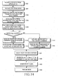
- FIG. 14 is a flowchart illustrating a process of transmitting data streams in a transmitter according to an exemplary embodiment of the present invention. With reference to FIG. 14, a description will now be made of a process of transmitting data streams in a transmitter according to an exemplary embodiment of the present invention.
- a transmitter receives a data stream of each user from an upper layer.
- the transmitter gathers CSI information fed back from a receiver.
- the transmitter prepares all possible space pre-coding methods. If the transmitter uses space pre-coding, the space pre-coding method is not determined in this step.
- the transmitter performs scheduling on all the possible space pre-coding methods.
- the transmitter determines which user data stream is to be scheduled by its scheduler.
- the scheduling is performed based on the space pre-coding method determined in step 1403.
- the scheduled user's data stream is converted into a modulation signal through a coding and modulation process in step 1405.
- the transmitter determines in step 1411 whether a pre-coding method to be used is a space pre-coding method.
- the pre-coding method is changed according to whether the pre-coding method to be used is a space pre-coding method or an opportunistic pre-coding method.
- either the system or the user can select one of the space pre-coding method or the opportunistic pre-coding method. That is, all users in the system can use one pre-coding method. Otherwise, some users can use the space pre-coding method, and the other users can use the opportunistic pre-coding method.
- the transmitter uses the space pre-coding method, it receives a pre-coding command from the scheduler in step 1412, and performs space pre-coding in step 1413.
- the transmitter users the opportunistic pre-coding method, it generates a pre-coding command according to a predefined pattern in step 1414, and performs space pre-coding according to the command in step 1415.
- the transmitter attaches a pilot signal to the pre-coded signal in step 1431, and converts the pilot-attached signal into an OFDM symbol by OFDM modulation in step 1432.
- the transmitter converts the baseband OFDM symbol into an RF signal by RF processing in step 1433, and then transmits the RF signal via multiple transmission antennas in step 1434.
- FIG. 15 is a flowchart illustrating a process of receiving data streams in a receiver according to an exemplary embodiment of the present invention. With reference to FIG. 15, a description will now be made of a process of receiving data streams in a receiver according to an exemplary embodiment of the present invention.
- a receiver receives RF signals from multiple reception antennas in step 1500, and converts the RF signals into baseband signals in step 1501. Because the converted baseband signals are OFDM symbols, the receiver restores in step 1502 the modulation signals carried by each sub-carrier using an OFDM demodulator. Thereafter, the receiver extracts a pilot and a control signal in step 1503, and estimates a MIMO channel using the extracted pilot in step 1504.
- the receiver performs a process of estimating a pre-coded MIMO channel.
- the receiver generates the space pre-coding command used in a transmitter in step 1505, and estimates a pre-coded MIMO channel using the generated value in step 1506.
- the receiver uses the estimated pre-coded MIMO channel in generating a CSI feedback value.
- the receiver can restore the modulation signal to which the space pre-coding method is applied. Therefore, the receiver restores a control signal necessary for data restoration in step 1507, and extracts data based on the control signal in step 1508.
- step 1509 the receiver combines the extracted data based on the estimated pre-coded MIMO channel.
- the receiver finally demodulates and decodes the combined signal, thereby restoring the transmitted data stream.
- the space pre-coder and the opportunistic pre-coder proposed in the present invention can implement various MIMO technologies such as beamforming, spatial multiplexing, and SDMA according to the decision of the scheduler.
- the opportunistic space pre-coder Because the opportunistic space pre-coder has no need to receive CSI feedback associated with space pre-coding from the receiver to determine the space pre-coding method, it can obtain the improved system capacity with the same amount of feedback as that of the PARC.
- the opportunistic space pre-coder can have an effect of intentionally changing a channel according to frequency and time when it experiences a bad channel status in the channel environment where a change in the channel according to frequency and time is very inconsiderable. This effect can be obtained by applying a different space pre-coding method every sub-band and time slot which is a unit of AMC and channel sensitive scheduling.
- the present invention contributes to an increase in system capacity and a decrease in overhead load.
Applications Claiming Priority (1)
| Application Number | Priority Date | Filing Date | Title |
|---|---|---|---|
| KR1020050103554A KR100996023B1 (ko) | 2005-10-31 | 2005-10-31 | 다중 안테나 통신 시스템에서 데이터 송수신 장치 및 방법 |
Publications (3)
| Publication Number | Publication Date |
|---|---|
| EP1780925A2 true EP1780925A2 (fr) | 2007-05-02 |
| EP1780925A3 EP1780925A3 (fr) | 2012-09-19 |
| EP1780925B1 EP1780925B1 (fr) | 2018-10-10 |
Family
ID=37685150
Family Applications (1)
| Application Number | Title | Priority Date | Filing Date |
|---|---|---|---|
| EP06022705.5A Not-in-force EP1780925B1 (fr) | 2005-10-31 | 2006-10-31 | Système de communication à antennes multiples utilisant un précodeur spatial |
Country Status (8)
| Country | Link |
|---|---|
| US (1) | US7697622B2 (fr) |
| EP (1) | EP1780925B1 (fr) |
| JP (1) | JP5161098B2 (fr) |
| KR (1) | KR100996023B1 (fr) |
| CN (1) | CN101300749B (fr) |
| RU (1) | RU2369966C1 (fr) |
| TW (1) | TWI332785B (fr) |
| WO (1) | WO2007052941A1 (fr) |
Cited By (18)
| Publication number | Priority date | Publication date | Assignee | Title |
|---|---|---|---|---|
| WO2008147122A1 (fr) * | 2007-06-01 | 2008-12-04 | Samsung Electronics Co., Ltd. | Procédé et appareil de mise en correspondance de symboles de modulation avec des ressources dans des systèmes ofdm |
| WO2009003035A2 (fr) * | 2007-06-26 | 2008-12-31 | Broadcom Corporation | Procede et systeme d'adaptation entre differentes techniques en boucle fermee, en boucle ouverte et hybrides pour des systemes a antennes multiples |
| WO2008153479A3 (fr) * | 2007-06-14 | 2009-02-12 | Ericsson Telefon Ab L M | Procédé et appareil de commande d'une transmission multi-antennes dans un réseau de communication sans fil |
| EP2034682A2 (fr) * | 2007-09-07 | 2009-03-11 | Broadcom Corporation | Formation de faisceaux utilisant un livre de codage pour la communication MIMO à plusieurs utilisateurs |
| WO2009042290A1 (fr) * | 2007-09-28 | 2009-04-02 | Freescale Semiconductor, Inc. | Procédé de retransmission destiné au protocole harq dans des systèmes mimo |
| WO2009132092A2 (fr) * | 2008-04-22 | 2009-10-29 | Texas Instruments Incorporated | Rang et pmi dans signalisation de commande de téléchargement pour mimo à un seul utilisateur de liaison montante (ul su-mimo) |
| EP2119056A2 (fr) * | 2007-07-12 | 2009-11-18 | LG Electronics Inc. | Procédé de transmission d'une requête de programmation dans un système de communication sans fil |
| EP2227866A2 (fr) * | 2007-12-31 | 2010-09-15 | LG Electronics Inc. | Procédé servant à transmettre un signal précodé dans un système de communication collaboratif multi-entrées multi-sorties |
| CN102130753A (zh) * | 2010-01-20 | 2011-07-20 | 美国博通公司 | 一种处理信号的方法和系统 |
| EP2355370A1 (fr) * | 2010-01-20 | 2011-08-10 | Broadcom Corporation | Procédé et système pour la formation de faisceau orthogonal dans des systèmes de communication à utilisateurs multiples et entrées et sorties multiples (MU-MIMO) |
| US8184544B2 (en) | 2007-08-10 | 2012-05-22 | Lg Electronics Inc. | Method of transmitting feedback data in a multiple antenna system |
| CN101686214B (zh) * | 2008-09-26 | 2012-12-05 | 电信科学技术研究院 | 一种进行信道质量指示估计的方法及装置 |
| US8400950B2 (en) | 2007-06-25 | 2013-03-19 | Lg Electronics Inc. | Method of transmitting data in multiple antenna system |
| US8406184B2 (en) | 2007-10-01 | 2013-03-26 | Ntt Docomo, Inc. | User apparatus, base station apparatus and method in mobile communications system |
| US8457235B2 (en) | 2007-06-25 | 2013-06-04 | Lg Electronics Inc. | Method of transmitting feedback data in multiple antenna system |
| US8509324B2 (en) | 2008-07-08 | 2013-08-13 | Qualcomm Incorporated | Methods and systems for reducing PAPR of an OFDM signal |
| US8908632B2 (en) | 2007-06-08 | 2014-12-09 | Samsung Electronics Co., Ltd. | Methods and apparatus for channel interleaving in OFDM systems |
| WO2018107068A1 (fr) * | 2016-12-09 | 2018-06-14 | Qualcomm Incorporated | Diversité et précodage d'une transmission en liaison montante |
Families Citing this family (169)
| Publication number | Priority date | Publication date | Assignee | Title |
|---|---|---|---|---|
| US7599420B2 (en) * | 2004-07-30 | 2009-10-06 | Rearden, Llc | System and method for distributed input distributed output wireless communications |
| US20070002724A1 (en) * | 2005-06-15 | 2007-01-04 | Samsung Electronics Co., Ltd. | Apparatus and method for broadcast superposition and cancellation in a multi-carrier wireless network |
| KR100842521B1 (ko) * | 2005-11-22 | 2008-07-01 | 삼성전자주식회사 | 통신 시스템에서 신호 송수신 장치 및 방법 |
| CN101039136B (zh) * | 2006-03-15 | 2011-09-14 | 华为技术有限公司 | 基于空频编码的多天线发射分集方法及其系统 |
| WO2007106980A1 (fr) * | 2006-03-17 | 2007-09-27 | Nortel Networks Limited | Systèmes et procédés mimo à boucle fermée |
| US8116391B2 (en) * | 2006-05-26 | 2012-02-14 | Wi-Lan Inc. | Quantization of channel state information in multiple antenna systems |
| US8929485B2 (en) * | 2006-06-16 | 2015-01-06 | Samsung Electronics Co., Ltd. | System and method for broadcast pre-coding in a MIMO system |
| KR100899744B1 (ko) * | 2006-09-11 | 2009-05-27 | 삼성전자주식회사 | 이동통신 시스템에서 제어 채널 메시지를 송수신하는 장치 및 방법 |
| JP4976498B2 (ja) | 2006-10-02 | 2012-07-18 | エルジー エレクトロニクス インコーポレイティド | 効率的な多重化を用いた制御信号送信方法 |
| EP2077056B1 (fr) | 2006-10-02 | 2016-03-09 | LG Electronics, Inc. | Procédé de transmission d'un signal de commande en liaison descendante |
| TWI470957B (zh) * | 2006-10-30 | 2015-01-21 | Interdigital Tech Corp | 無線通信系統中處理反饋方法及裝置 |
| US7983366B2 (en) | 2006-12-05 | 2011-07-19 | Intel Corporation | Transmission signaling techniques to enhance receiver interference mitigation performance |
| TWI452859B (zh) | 2007-01-05 | 2014-09-11 | Lg Electronics Inc | 用於mimo系統之層對映方法與資料傳輸 |
| KR101346423B1 (ko) * | 2007-06-19 | 2014-01-02 | 엘지전자 주식회사 | 다중 안테나 시스템에서 데이터 전송 방법 |
| KR100969771B1 (ko) * | 2007-01-31 | 2010-07-13 | 삼성전자주식회사 | 통신 시스템에서 신호 송수신 장치 및 방법 |
| KR101306729B1 (ko) * | 2007-02-05 | 2013-09-11 | 엘지전자 주식회사 | 피드백 정보 송수신 방법 |
| CN104639306B (zh) | 2007-03-19 | 2019-04-16 | Lg电子株式会社 | 移动通信系统中资源分配及传输/接收资源分配信息的方法 |
| KR101049138B1 (ko) | 2007-03-19 | 2011-07-15 | 엘지전자 주식회사 | 이동 통신 시스템에서, 수신확인신호 수신 방법 |
| US8290079B2 (en) * | 2007-04-19 | 2012-10-16 | Interdigital Technology Corporation | Method and apparatus for precoding validation in wireless communications |
| US20080267056A1 (en) * | 2007-04-26 | 2008-10-30 | Motorola, Inc. | Method and apparatus for performing multi-antenna transmission |
| DK2143225T3 (en) | 2007-04-30 | 2018-05-28 | Interdigital Tech Corp | Feedback signal signaling error detection and check in MIMO wireless communication systems |
| US8982969B2 (en) * | 2007-05-03 | 2015-03-17 | Broadcom Corporation | Method and system for CQI/PMI feedback for precoded MIMO systems utilizing differential codebooks |
| TW200847669A (en) * | 2007-05-24 | 2008-12-01 | Chung Shan Inst Of Science | Wireless transmission system and its transmission method of multiple input and output |
| EP2151934A1 (fr) * | 2007-05-28 | 2010-02-10 | Mitsubishi Electric Corporation | Appareil de communication |
| KR101409115B1 (ko) * | 2007-06-08 | 2014-06-17 | 엘지전자 주식회사 | 다중 안테나 시스템에서 가중치 정보 전송 방법 |
| KR100913090B1 (ko) | 2007-06-13 | 2009-08-21 | 엘지전자 주식회사 | 통신 시스템에서 확산 신호를 송신하는 방법 |
| KR100908063B1 (ko) | 2007-06-13 | 2009-07-15 | 엘지전자 주식회사 | 이동 통신 시스템에서 확산신호를 송신하는 방법 |
| CN102938665B (zh) | 2007-06-19 | 2015-09-30 | 株式会社Ntt都科摩 | 发送装置以及发送方法 |
| KR100900289B1 (ko) | 2007-06-21 | 2009-05-29 | 엘지전자 주식회사 | 직교 주파수 분할 다중화 시스템에서 제어 채널을 송수신하는 방법 |
| CN101868988B (zh) * | 2007-07-16 | 2014-09-24 | 黑莓有限公司 | 在无线网络中提供空分多址 |
| CN101355381A (zh) * | 2007-07-24 | 2009-01-28 | 株式会社Ntt都科摩 | 基于信道向量量化的调度和预编码方法及装置 |
| US7907677B2 (en) * | 2007-08-10 | 2011-03-15 | Intel Corporation | Open loop MU-MIMO |
| US8223855B2 (en) * | 2007-08-10 | 2012-07-17 | Motorola Mobility, Inc. | Method for blindly detecting a precoding matrix index |
| US8798183B2 (en) * | 2007-08-13 | 2014-08-05 | Qualcomm Incorporated | Feedback and rate adaptation for MIMO transmission in a time division duplexed (TDD) communication system |
| KR101397359B1 (ko) | 2007-08-14 | 2014-05-19 | 엘지전자 주식회사 | 다중안테나 시스템에서의 채널정보 전송방법 |
| US8009617B2 (en) * | 2007-08-15 | 2011-08-30 | Qualcomm Incorporated | Beamforming of control information in a wireless communication system |
| US8014265B2 (en) * | 2007-08-15 | 2011-09-06 | Qualcomm Incorporated | Eigen-beamforming for wireless communication systems |
| US8102934B2 (en) * | 2007-08-16 | 2012-01-24 | Samsung Electronics Co., Ltd. | Transmitting apparatus and method |
| CN101373998B (zh) | 2007-08-20 | 2012-07-25 | 上海贝尔阿尔卡特股份有限公司 | 低信息交互的多基站协作mimo及其调度方法和装置 |
| KR100997573B1 (ko) * | 2007-08-31 | 2010-11-30 | 후지쯔 가부시끼가이샤 | 피드백 장치, 피드백 방법, 스케줄링 장치 및 스케줄링 방법 |
| CN101485130B (zh) * | 2007-08-31 | 2012-10-03 | 富士通株式会社 | 无线通信系统和无线通信方法 |
| US8036282B2 (en) | 2007-09-07 | 2011-10-11 | Wi-Lan Inc. | Multi-tiered quantization of channel state information in multiple antenna systems |
| US8553624B2 (en) | 2007-10-10 | 2013-10-08 | Samsung Electronics Co., Ltd. | Asynchronous hybrid ARQ process indication in a MIMO wireless communication system |
| CN101409605A (zh) * | 2007-10-12 | 2009-04-15 | Nxp股份有限公司 | 无线通信系统中管理传输资源的方法和系统 |
| JP5269098B2 (ja) * | 2008-01-14 | 2013-08-21 | テレフオンアクチーボラゲット エル エム エリクソン(パブル) | Mimo通信における開ループ事前符号化器循環 |
| JP5047834B2 (ja) * | 2008-02-15 | 2012-10-10 | 株式会社エヌ・ティ・ティ・ドコモ | 無線通信装置及び無線通信方法 |
| KR101430490B1 (ko) * | 2008-02-28 | 2014-08-14 | 엘지전자 주식회사 | 데이터 정보와 제어 정보의 다중화 방법 |
| WO2009107985A1 (fr) | 2008-02-28 | 2009-09-03 | Lg Electronics Inc. | Procédé de multiplexage de données et d’information de commande |
| US8233939B2 (en) * | 2008-03-31 | 2012-07-31 | Intel Corporation | Multiuser sector micro diversity system |
| KR101468741B1 (ko) * | 2008-04-04 | 2014-12-04 | 엘지전자 주식회사 | 무선통신 시스템에서 채널 정보 전송 방법 |
| US8234546B2 (en) | 2008-04-21 | 2012-07-31 | Wi-Lan, Inc. | Mitigation of transmission errors of quantized channel state information feedback in multi antenna systems |
| JP5036869B2 (ja) * | 2008-06-23 | 2012-09-26 | シャープ株式会社 | 移動局装置、通信システムおよび通信方法 |
| JP2010010966A (ja) * | 2008-06-25 | 2010-01-14 | Sumitomo Electric Ind Ltd | 無線通信装置、及びmimo無線通信における信号送信方法 |
| US8462737B1 (en) * | 2008-06-27 | 2013-06-11 | Research In Motion Limited | System and method for a MIMO split-physical layer scheme for a wireless network |
| KR101475816B1 (ko) * | 2008-07-07 | 2014-12-23 | 삼성전자주식회사 | 다중 입출력 무선통신 시스템에서 셀 간 간섭 제거 장치 및방법 |
| EP2297868A4 (fr) * | 2008-07-07 | 2014-08-06 | Commw Scient Ind Res Org | Systèmes ofdm à entrées multiples et à sorties multiples |
| KR101498059B1 (ko) * | 2008-07-22 | 2015-03-03 | 엘지전자 주식회사 | 파일롯 서브캐리어 할당을 사용하는 복수개의 송신 안테나를 갖는 무선 통신 시스템 |
| US8867565B2 (en) | 2008-08-21 | 2014-10-21 | Qualcomm Incorporated | MIMO and SDMA signaling for wireless very high throughput systems |
| JP5256955B2 (ja) * | 2008-09-12 | 2013-08-07 | 富士通株式会社 | 制御方法、通信特性制御方法、基地局装置、及び移動局装置 |
| US8693442B2 (en) | 2008-09-22 | 2014-04-08 | Blackberry Limited | Multi-site MIMO cooperation in cellular network |
| EP2169888A1 (fr) * | 2008-09-30 | 2010-03-31 | NTT DoCoMo Inc. | Estimateur de canal radio assistée par pilote tridimensionnel |
| US8200286B2 (en) * | 2008-10-31 | 2012-06-12 | Telefonaktiebolaget L M Ericsson (Publ) | Base station and method for improving coverage in a wireless communication system using antenna beam-jitter and CQI correction |
| GB0820535D0 (en) * | 2008-11-10 | 2008-12-17 | Icera Inc | Communication system and method |
| KR101460745B1 (ko) * | 2009-02-19 | 2014-11-11 | 삼성전자주식회사 | 무선 통신 시스템에서 다중입력 다중출력과 빔포밍을 동시에 지원하기 위한 장치 및 방법 |
| KR101040605B1 (ko) * | 2009-02-27 | 2011-06-10 | 연세대학교 산학협력단 | 공간 변조 방법과 장치, 그리고 공간 변조된 신호의 복조 방법과 장치 |
| WO2010105345A1 (fr) | 2009-03-16 | 2010-09-23 | Nortel Networks Limited | Transmission utilisant des pilotes communs et dédiés |
| US8355455B2 (en) * | 2009-04-28 | 2013-01-15 | Qualcomm Incorporated | Using channel estimates associated with OFDM pilot symbols to estimate additional parameters |
| US9565011B2 (en) | 2009-06-04 | 2017-02-07 | Qualcomm Incorporated | Data transmission with cross-subframe control in a wireless network |
| US9497775B2 (en) | 2009-07-07 | 2016-11-15 | Lg Electronics Inc. | Method and apparatus for carrier scheduling in a multi-carrier system |
| CN101692665B (zh) * | 2009-09-28 | 2012-07-18 | 中兴通讯股份有限公司 | 正交频分复用-多输入多输出系统的解调方法及解调器 |
| CN102055570B (zh) * | 2009-11-10 | 2014-12-17 | 华为技术有限公司 | 半静态调度数据的传输方法及装置 |
| US8434336B2 (en) * | 2009-11-14 | 2013-05-07 | Qualcomm Incorporated | Method and apparatus for managing client initiated transmissions in multiple-user communication schemes |
| US8605809B2 (en) * | 2009-11-25 | 2013-12-10 | Telefonaktiebolaget Lm Ericsson | Method and apparatus for using factorized precoding |
| TWI562554B (en) * | 2009-12-30 | 2016-12-11 | Sony Corp | Communications system and device using beamforming |
| US9253784B2 (en) * | 2010-01-11 | 2016-02-02 | Samsung Electronics Co., Ltd. | Method and system for enabling resource block bundling in LTE-A systems |
| JP5134635B2 (ja) * | 2010-01-18 | 2013-01-30 | 株式会社エヌ・ティ・ティ・ドコモ | 無線基地局装置、移動端末装置及び無線通信方法 |
| CN102158971B (zh) * | 2010-02-11 | 2014-11-05 | 华为技术有限公司 | 实现半持续调度业务或类似半持续调度业务的方法及设备 |
| US8953522B2 (en) | 2010-03-29 | 2015-02-10 | Samsung Electronics Co., Ltd. | Method and apparatus for controlling retransmission on uplink in a wireless communication system supporting MIMO |
| KR101817724B1 (ko) * | 2010-04-30 | 2018-02-21 | 삼성전자주식회사 | 각 리포팅 모드에 대응하는 코드북을 사용하는 다중 입출력 통신 시스템 |
| US9887754B2 (en) | 2010-05-04 | 2018-02-06 | Qualcomm Incorporated | Method and apparatus for optimizing power distribution between symbols |
| EP2797251B1 (fr) * | 2010-05-10 | 2017-08-30 | Telefonaktiebolaget LM Ericsson (publ) | Système et procédé pour attribuer des ressources de transmission |
| US8599761B2 (en) * | 2010-05-14 | 2013-12-03 | Samsung Electronics Co., Ltd. | Systems and methods for PUCCH feedback in 3GPP wireless networks |
| US9071285B2 (en) | 2011-05-26 | 2015-06-30 | Cohere Technologies, Inc. | Modulation and equalization in an orthonormal time-frequency shifting communications system |
| US10667148B1 (en) | 2010-05-28 | 2020-05-26 | Cohere Technologies, Inc. | Methods of operating and implementing wireless communications systems |
| US9071286B2 (en) | 2011-05-26 | 2015-06-30 | Cohere Technologies, Inc. | Modulation and equalization in an orthonormal time-frequency shifting communications system |
| US9130638B2 (en) | 2011-05-26 | 2015-09-08 | Cohere Technologies, Inc. | Modulation and equalization in an orthonormal time-frequency shifting communications system |
| US9444514B2 (en) | 2010-05-28 | 2016-09-13 | Cohere Technologies, Inc. | OTFS methods of data channel characterization and uses thereof |
| US8976851B2 (en) | 2011-05-26 | 2015-03-10 | Cohere Technologies, Inc. | Modulation and equalization in an orthonormal time-frequency shifting communications system |
| US10681568B1 (en) | 2010-05-28 | 2020-06-09 | Cohere Technologies, Inc. | Methods of data channel characterization and uses thereof |
| US11943089B2 (en) | 2010-05-28 | 2024-03-26 | Cohere Technologies, Inc. | Modulation and equalization in an orthonormal time-shifting communications system |
| US10050680B2 (en) * | 2010-06-07 | 2018-08-14 | Entropic Communications, Llc | Method and apparatus for real time multiplexing with transmitter and antenna array elements |
| CN101877627B (zh) * | 2010-06-21 | 2015-09-16 | 中兴通讯股份有限公司 | 信道状态信息的反馈方法及终端 |
| WO2012077299A1 (fr) * | 2010-12-10 | 2012-06-14 | パナソニック株式会社 | Procédé de génération de signaux et dispositif de génération de signaux |
| JP5991572B2 (ja) * | 2011-02-28 | 2016-09-14 | サン パテント トラスト | 送信方法および送信装置 |
| US9031141B2 (en) | 2011-05-26 | 2015-05-12 | Cohere Technologies, Inc. | Modulation and equalization in an orthonormal time-frequency shifting communications system |
| CA2844102A1 (fr) * | 2011-08-04 | 2013-02-07 | Warren GROSSMAN | Systeme de communication pour des communications sans fil a codage spatial |
| WO2013025236A1 (fr) * | 2011-08-12 | 2013-02-21 | Intel Corporation | Système et procédé de régulation de puissance sur la liaison montante dans un système de communication sans fil |
| US9219533B2 (en) * | 2011-10-25 | 2015-12-22 | Transpacific Ip Management Group Ltd. | Systems and methods for downlink scheduling in multiple input multiple output wireless communications systems |
| US9450659B2 (en) * | 2011-11-04 | 2016-09-20 | Alcatel Lucent | Method and apparatus to generate virtual sector wide static beams using phase shift transmit diversity |
| CN104012031B (zh) | 2011-12-22 | 2017-07-21 | 英特尔公司 | 用于执行jh加密散列的指令 |
| CN104011709B (zh) | 2011-12-22 | 2018-06-05 | 英特尔公司 | 在256位数据路径中执行jh加密散列的指令 |
| US10469215B2 (en) | 2012-06-25 | 2019-11-05 | Cohere Technologies, Inc. | Orthogonal time frequency space modulation system for the Internet of Things |
| US9912507B2 (en) | 2012-06-25 | 2018-03-06 | Cohere Technologies, Inc. | Orthogonal time frequency space communication system compatible with OFDM |
| US9929783B2 (en) | 2012-06-25 | 2018-03-27 | Cohere Technologies, Inc. | Orthogonal time frequency space modulation system |
| US10003487B2 (en) | 2013-03-15 | 2018-06-19 | Cohere Technologies, Inc. | Symplectic orthogonal time frequency space modulation system |
| US10411843B2 (en) | 2012-06-25 | 2019-09-10 | Cohere Technologies, Inc. | Orthogonal time frequency space communication system compatible with OFDM |
| US10090972B2 (en) | 2012-06-25 | 2018-10-02 | Cohere Technologies, Inc. | System and method for two-dimensional equalization in an orthogonal time frequency space communication system |
| US9967758B2 (en) | 2012-06-25 | 2018-05-08 | Cohere Technologies, Inc. | Multiple access in an orthogonal time frequency space communication system |
| EP2909986B1 (fr) * | 2012-10-18 | 2020-03-11 | Commonwealth Scientific and Industrial Research Organisation | Communications ofdm |
| US9706547B2 (en) * | 2013-01-16 | 2017-07-11 | Industrial Technology Research Institute | Method of handling communication operations and related communication device |
| KR101561740B1 (ko) * | 2013-11-26 | 2015-10-20 | 포항공과대학교 산학협력단 | 분산 안테나 시스템의 부반송파간 간섭 제거 방법 및 이를 수행하는 장치 |
| CN104917554B (zh) * | 2014-03-10 | 2019-05-10 | 华为技术有限公司 | 基站及形成波束的方法 |
| WO2016013698A1 (fr) * | 2014-07-24 | 2016-01-28 | 엘지전자 주식회사 | Procédé et appareil pour transmettre des signaux de rétroaction |
| EP3188528B1 (fr) * | 2014-07-25 | 2018-09-12 | Ntt Docomo, Inc. | Station de radiotransmission et réseau de radiocommunication |
| CN105450343B (zh) * | 2014-08-30 | 2018-11-06 | 华为技术有限公司 | 一种预编码的方法、装置及系统 |
| KR20160075995A (ko) * | 2014-12-19 | 2016-06-30 | 한국전자통신연구원 | 물리 채널 전송 방법 및 장치 |
| US10090973B2 (en) | 2015-05-11 | 2018-10-02 | Cohere Technologies, Inc. | Multiple access in an orthogonal time frequency space communication system |
| CN107925434B (zh) | 2015-05-11 | 2021-02-05 | 凝聚技术公司 | 用于数据的辛正交时频移位调制和传输的系统和方法 |
| US9866363B2 (en) | 2015-06-18 | 2018-01-09 | Cohere Technologies, Inc. | System and method for coordinated management of network access points |
| US10574317B2 (en) | 2015-06-18 | 2020-02-25 | Cohere Technologies, Inc. | System and method for providing wireless communication services using configurable broadband infrastructure shared among multiple network operators |
| EP4164152A1 (fr) | 2015-06-27 | 2023-04-12 | Cohere Technologies, Inc. | Système de communication par espace temps-fréquence orthogonal compatible avec ofdm |
| US9838290B2 (en) | 2015-06-30 | 2017-12-05 | Ciena Corporation | Flexible ethernet operations, administration, and maintenance systems and methods |
| US10892547B2 (en) | 2015-07-07 | 2021-01-12 | Cohere Technologies, Inc. | Inconspicuous multi-directional antenna system configured for multiple polarization modes |
| US10693581B2 (en) | 2015-07-12 | 2020-06-23 | Cohere Technologies, Inc. | Orthogonal time frequency space modulation over a plurality of narrow band subcarriers |
| WO2017044501A1 (fr) | 2015-09-07 | 2017-03-16 | Cohere Technologies | Accès multiple par modulation orthogonale d'espace temps-fréquence |
| WO2017087706A1 (fr) | 2015-11-18 | 2017-05-26 | Cohere Technologies | Techniques de modulation d'espace temps-fréquence orthogonal |
| CN108781072B (zh) | 2015-12-09 | 2022-04-26 | 凝聚技术公司 | 利用复正交函数的导频封装 |
| CN106936751B (zh) * | 2015-12-30 | 2019-08-23 | 北京信威通信技术股份有限公司 | 数据传输方法及装置 |
| CN115694764A (zh) | 2016-02-25 | 2023-02-03 | 凝聚技术公司 | 用于无线通信的参考信号封装 |
| WO2017165697A1 (fr) | 2016-03-23 | 2017-09-28 | Cohere Technologies | Traitement côté récepteur des signaux modulés dans l'espace de fréquence temporelle orthogonale |
| CN117097594A (zh) | 2016-03-31 | 2023-11-21 | 凝聚技术公司 | 使用正交时间频率空间调制的导频信号的信道获取 |
| US9667307B1 (en) | 2016-03-31 | 2017-05-30 | Cohere Technologies | Wireless telecommunications system for high-mobility applications |
| US10063295B2 (en) | 2016-04-01 | 2018-08-28 | Cohere Technologies, Inc. | Tomlinson-Harashima precoding in an OTFS communication system |
| CN113726700A (zh) | 2016-04-01 | 2021-11-30 | 凝聚技术公司 | 正交时频空间调制信号的迭代二维均衡 |
| MX2018012764A (es) * | 2016-04-27 | 2019-01-10 | Panasonic Ip Corp America | Aparato de transmision y metodo de transmision. |
| KR102385494B1 (ko) | 2016-04-27 | 2022-04-11 | 파나소닉 인텔렉츄얼 프로퍼티 코포레이션 오브 아메리카 | 수신 장치, 수신 방법 및 집적 회로 |
| CN107370525B (zh) | 2016-05-12 | 2021-03-30 | 华为技术有限公司 | 用于信道状态信息反馈的方法、基站、终端设备及系统 |
| EP3446416B1 (fr) * | 2016-05-13 | 2020-11-04 | Huawei Technologies Co., Ltd. | Précodage et acquisition d'informations d'état de canal pour des transmissions de multiples flux dans des systèmes mimo massifs |
| US10938602B2 (en) | 2016-05-20 | 2021-03-02 | Cohere Technologies, Inc. | Iterative channel estimation and equalization with superimposed reference signals |
| EP3497799A4 (fr) | 2016-08-12 | 2020-04-15 | Cohere Technologies, Inc. | Égalisation et décodage itératifs multiniveaux |
| WO2018031938A1 (fr) | 2016-08-12 | 2018-02-15 | Cohere Technologies | Multiplexage multi-utilisateurs de signaux d'espace temps-fréquence orthogonaux |
| WO2018032016A1 (fr) | 2016-08-12 | 2018-02-15 | Cohere Technologies | Égalisation localisée pour canaux à interférence interporteuse |
| IL265407B2 (en) | 2016-09-19 | 2023-04-01 | Guangdong Oppo Mobile Telecommunications Corp Ltd | Method and device for transmitting signals |
| US11310000B2 (en) | 2016-09-29 | 2022-04-19 | Cohere Technologies, Inc. | Transport block segmentation for multi-level codes |
| US10965348B2 (en) | 2016-09-30 | 2021-03-30 | Cohere Technologies, Inc. | Uplink user resource allocation for orthogonal time frequency space modulation |
| WO2018106731A1 (fr) | 2016-12-05 | 2018-06-14 | Cohere Technologies | Accès sans fil fixe au moyen d'une modulation orthogonale d'espace temps-fréquence |
| EP3566379A4 (fr) | 2017-01-09 | 2020-09-09 | Cohere Technologies, Inc. | Brouillage de pilote pour estimation de voie |
| US10356632B2 (en) | 2017-01-27 | 2019-07-16 | Cohere Technologies, Inc. | Variable beamwidth multiband antenna |
| US10568143B2 (en) | 2017-03-28 | 2020-02-18 | Cohere Technologies, Inc. | Windowed sequence for random access method and apparatus |
| US11817987B2 (en) | 2017-04-11 | 2023-11-14 | Cohere Technologies, Inc. | Digital communication using dispersed orthogonal time frequency space modulated signals |
| EP3613243B1 (fr) | 2017-04-21 | 2022-08-24 | Cohere Technologies, Inc. | Techniques de communication utilisant des propriétés quasi-statiques de canaux sans fil |
| US11063804B2 (en) | 2017-04-24 | 2021-07-13 | Cohere Technologies, Inc. | Digital communication using lattice division multiplexing |
| WO2018200567A1 (fr) | 2017-04-24 | 2018-11-01 | Cohere Technologies | Conceptions et fonctionnement d'antenne multifaisceau |
| CN111052692B (zh) | 2017-07-12 | 2022-10-11 | 凝聚技术公司 | 基于zak变换的数据调制方法 |
| WO2019032605A1 (fr) | 2017-08-11 | 2019-02-14 | Cohere Technologies | Technique de traçage de rayon pour mesures de canal sans fil |
| WO2019036492A1 (fr) | 2017-08-14 | 2019-02-21 | Cohere Technologies | Attribution de ressources de transmission par division de blocs de ressources physiques |
| WO2019051093A1 (fr) | 2017-09-06 | 2019-03-14 | Cohere Technologies | Réduction de treillis en modulation temporelle, fréquentielle et spatiale orthogonale |
| WO2019051427A1 (fr) | 2017-09-11 | 2019-03-14 | Cohere Technologies, Inc. | Réseaux locaux sans fil utilisant la modulation orthogonale d'espace temps-fréquence |
| US11190308B2 (en) | 2017-09-15 | 2021-11-30 | Cohere Technologies, Inc. | Achieving synchronization in an orthogonal time frequency space signal receiver |
| EP3685470A4 (fr) | 2017-09-20 | 2021-06-23 | Cohere Technologies, Inc. | Réseau d'alimentation électromagnétique à faible coût |
| WO2019068053A1 (fr) | 2017-09-29 | 2019-04-04 | Cohere Technologies, Inc. | Correction d'erreurs sans circuit de retour à l'aide de codes de contrôle de parité à faible densité non binaire |
| US10873482B2 (en) * | 2017-10-18 | 2020-12-22 | Qualcomm Incorporated | Transmitter schemes to facilitate side channel information estimation |
| CN111919394B (zh) | 2017-11-01 | 2022-05-27 | 凝聚技术公司 | 使用正交时频空分复用的无线系统中的预编码 |
| WO2019113046A1 (fr) | 2017-12-04 | 2019-06-13 | Cohere Technologies, Inc. | Mise en oeuvre d'une modulation temporelle, fréquentielle et spatiale orthogonale pour des communications sans fil |
| WO2019157230A1 (fr) | 2018-02-08 | 2019-08-15 | Cohere Technologies, Inc. | Aspects d'estimation de canal pour une modulation spatiale temps-fréquence orthogonale pour des communications sans fil |
| WO2019173775A1 (fr) | 2018-03-08 | 2019-09-12 | Cohere Technologies, Inc. | Planification de transmissions mimo multi-utilisateur dans des systèmes de communication sans fil fixes |
| US11329848B2 (en) | 2018-06-13 | 2022-05-10 | Cohere Technologies, Inc. | Reciprocal calibration for channel estimation based on second-order statistics |
| US11522600B1 (en) | 2018-08-01 | 2022-12-06 | Cohere Technologies, Inc. | Airborne RF-head system |
| CN110233711A (zh) * | 2019-06-10 | 2019-09-13 | 唐利(上海)信息科技有限公司 | 一种混合自动重传请求的信息处理方法及装置 |
Citations (1)
| Publication number | Priority date | Publication date | Assignee | Title |
|---|---|---|---|---|
| US20050063378A1 (en) * | 2003-09-09 | 2005-03-24 | Tamer Kadous | Incremental redundancy transmission for multiple parallel channels in a MIMO communication system |
Family Cites Families (22)
| Publication number | Priority date | Publication date | Assignee | Title |
|---|---|---|---|---|
| US6185440B1 (en) * | 1997-12-10 | 2001-02-06 | Arraycomm, Inc. | Method for sequentially transmitting a downlink signal from a communication station that has an antenna array to achieve an omnidirectional radiation |
| US6996418B2 (en) * | 2000-12-29 | 2006-02-07 | Nortel Networks Limited | Apparatus and method for OFDM data communications |
| US6859503B2 (en) * | 2001-04-07 | 2005-02-22 | Motorola, Inc. | Method and system in a transceiver for controlling a multiple-input, multiple-output communications channel |
| JP2003101504A (ja) * | 2001-09-21 | 2003-04-04 | Sony Corp | 送信装置および方法、通信システム、記録媒体、並びにプログラム |
| US6785431B2 (en) * | 2002-02-06 | 2004-08-31 | Lightwaves 2020, Inc. | Miniature circulator array devices and methods for making the same |
| US6862271B2 (en) * | 2002-02-26 | 2005-03-01 | Qualcomm Incorporated | Multiple-input, multiple-output (MIMO) systems with multiple transmission modes |
| US7103325B1 (en) * | 2002-04-05 | 2006-09-05 | Nortel Networks Limited | Adaptive modulation and coding |
| KR100896682B1 (ko) | 2002-04-09 | 2009-05-14 | 삼성전자주식회사 | 송/수신 다중 안테나를 포함하는 이동 통신 장치 및 방법 |
| US7095709B2 (en) * | 2002-06-24 | 2006-08-22 | Qualcomm, Incorporated | Diversity transmission modes for MIMO OFDM communication systems |
| US6940917B2 (en) * | 2002-08-27 | 2005-09-06 | Qualcomm, Incorporated | Beam-steering and beam-forming for wideband MIMO/MISO systems |
| US8320301B2 (en) * | 2002-10-25 | 2012-11-27 | Qualcomm Incorporated | MIMO WLAN system |
| JP4350491B2 (ja) * | 2002-12-05 | 2009-10-21 | パナソニック株式会社 | 無線通信システム、無線通信方法、及び無線通信装置 |
| KR100456477B1 (ko) * | 2002-12-24 | 2004-11-09 | 한국전자통신연구원 | 직교주파수 분할다중에서의 채널 정보 결정 시스템 및방법, 그 프로그램이 저장된 기록매체 |
| US6927728B2 (en) * | 2003-03-13 | 2005-08-09 | Motorola, Inc. | Method and apparatus for multi-antenna transmission |
| US20040235147A1 (en) * | 2003-05-21 | 2004-11-25 | Affymetrix, Inc. | System, method, and encased probe array product |
| US7460494B2 (en) * | 2003-08-08 | 2008-12-02 | Intel Corporation | Adaptive signaling in multiple antenna systems |
| US7302009B2 (en) * | 2003-12-17 | 2007-11-27 | Qualcomm Incorporated | Broadcast transmission with spatial spreading in a multi-antenna communication system |
| ATE491269T1 (de) * | 2003-12-22 | 2010-12-15 | Ericsson Telefon Ab L M | Verfahren zur bestimmung von sendegewichten |
| JP2005252834A (ja) * | 2004-03-05 | 2005-09-15 | Rikogaku Shinkokai | Mimo固有モード適応伝送システム及びmimo−ofdm固有モード適応伝送システム |
| US7447268B2 (en) * | 2004-03-31 | 2008-11-04 | Intel Corporation | OFDM system with per subcarrier phase rotation |
| EP1911171A1 (fr) * | 2005-07-29 | 2008-04-16 | The Governors of the University of Alberta | Appareil et procedes de selection d'antennes |
| US8102857B2 (en) * | 2007-02-02 | 2012-01-24 | Motorola Solutions, Inc. | System and method for processing data and control messages in a communication system |
-
2005
- 2005-10-31 KR KR1020050103554A patent/KR100996023B1/ko active IP Right Grant
-
2006
- 2006-10-31 US US11/589,985 patent/US7697622B2/en active Active
- 2006-10-31 TW TW095140247A patent/TWI332785B/zh not_active IP Right Cessation
- 2006-10-31 WO PCT/KR2006/004491 patent/WO2007052941A1/fr active Application Filing
- 2006-10-31 RU RU2008117119/09A patent/RU2369966C1/ru active
- 2006-10-31 JP JP2008537607A patent/JP5161098B2/ja not_active Expired - Fee Related
- 2006-10-31 CN CN200680040862.0A patent/CN101300749B/zh not_active Expired - Fee Related
- 2006-10-31 EP EP06022705.5A patent/EP1780925B1/fr not_active Not-in-force
Patent Citations (1)
| Publication number | Priority date | Publication date | Assignee | Title |
|---|---|---|---|---|
| US20050063378A1 (en) * | 2003-09-09 | 2005-03-24 | Tamer Kadous | Incremental redundancy transmission for multiple parallel channels in a MIMO communication system |
Non-Patent Citations (3)
| Title |
|---|
| HOWARD S ET AL: "A high-performance MIMO OFDM wireless LAN", IEEE COMMUNICATIONS MAGAZINE, IEEE SERVICE CENTER, PISCATAWAY, US, vol. 43, no. 2, 1 February 2005 (2005-02-01), pages 101-109, XP011126672, ISSN: 0163-6804 * |
| LUCENT TECHNOLOGIES: "Per Stream Rate Control with Code Reuse TxAA and APP Decoding for HSDPA", 3GPP DRAFT; R1-031077, 3RD GENERATION PARTNERSHIP PROJECT (3GPP), MOBILE COMPETENCE CENTRE ; 650, ROUTE DES LUCIOLES ; F-06921 SOPHIA-ANTIPOLIS CEDEX ; FRANCE, vol. RAN WG1, no. Seoul, Korea; 20031002, 2 October 2003 (2003-10-02), XP050098150, [retrieved on 2003-10-02] * |
| QUALCOMM EUROPE: "Qualitative Evaluation of MIMO schemes for OFDM-based E-", 3GPP DRAFT; R1-051267, 3RD GENERATION PARTNERSHIP PROJECT (3GPP), MOBILE COMPETENCE CENTRE ; 650, ROUTE DES LUCIOLES ; F-06921 SOPHIA-ANTIPOLIS CEDEX ; FRANCE, vol. RAN WG1, no. San Diego, USA; 20051014, 14 October 2005 (2005-10-14), XP050100854, [retrieved on 2005-10-14] * |
Cited By (55)
| Publication number | Priority date | Publication date | Assignee | Title |
|---|---|---|---|---|
| US8526392B2 (en) | 2007-06-01 | 2013-09-03 | Samsung Electronics Co., Ltd. | Methods and apparatus for mapping modulation symbols to resources in OFDM systems |
| US9118454B2 (en) | 2007-06-01 | 2015-08-25 | Samsung Electronics Co., Ltd. | Methods and apparatus for mapping modulation symbols to resources in OFDM systems |
| US10148394B2 (en) | 2007-06-01 | 2018-12-04 | Samsung Electronics Co., Ltd. | Methods and apparatus for mapping modulation symbols to resources in OFDM systems |
| WO2008147122A1 (fr) * | 2007-06-01 | 2008-12-04 | Samsung Electronics Co., Ltd. | Procédé et appareil de mise en correspondance de symboles de modulation avec des ressources dans des systèmes ofdm |
| US8937919B2 (en) | 2007-06-08 | 2015-01-20 | Samsung Electronics Co., Ltd. | Methods and apparatus for channel interleaving in OFDM systems |
| US8908632B2 (en) | 2007-06-08 | 2014-12-09 | Samsung Electronics Co., Ltd. | Methods and apparatus for channel interleaving in OFDM systems |
| US9444591B2 (en) | 2007-06-08 | 2016-09-13 | Samsung Electronics, Co., Ltd. | Methods and apparatus for channel interleaving in OFDM systems |
| WO2008153479A3 (fr) * | 2007-06-14 | 2009-02-12 | Ericsson Telefon Ab L M | Procédé et appareil de commande d'une transmission multi-antennes dans un réseau de communication sans fil |
| US8718165B2 (en) | 2007-06-14 | 2014-05-06 | Telefonaktiebolaget L M Ericsson (Publ) | Method and apparatus for controlling multi-antenna transmission in a wireless communication network |
| US8457235B2 (en) | 2007-06-25 | 2013-06-04 | Lg Electronics Inc. | Method of transmitting feedback data in multiple antenna system |
| US8400950B2 (en) | 2007-06-25 | 2013-03-19 | Lg Electronics Inc. | Method of transmitting data in multiple antenna system |
| US8320487B2 (en) | 2007-06-26 | 2012-11-27 | Broadcom Corporation | Method and system for adaptation between different closed-loop, open-loop and hybrid techniques for multiple antenna systems |
| WO2009003035A2 (fr) * | 2007-06-26 | 2008-12-31 | Broadcom Corporation | Procede et systeme d'adaptation entre differentes techniques en boucle fermee, en boucle ouverte et hybrides pour des systemes a antennes multiples |
| WO2009003035A3 (fr) * | 2007-06-26 | 2009-02-19 | Broadcom Corp | Procede et systeme d'adaptation entre differentes techniques en boucle fermee, en boucle ouverte et hybrides pour des systemes a antennes multiples |
| US9985767B2 (en) | 2007-07-12 | 2018-05-29 | Lg Electronics Inc. | Method of transmitting scheduling request in a wireless communication system |
| US7852743B2 (en) | 2007-07-12 | 2010-12-14 | Lg Electronics, Inc. | Method of transmitting scheduling request in a wireless communication system |
| EP2367391A1 (fr) * | 2007-07-12 | 2011-09-21 | Lg Electronics Inc. | Procédé de transmission d'une requête d'ordonnancement dans un système de communication sans fil et équipement d'utilisateur comprenant un processeur pour la transmission de la requête d'ordonnancement |
| US9357530B2 (en) | 2007-07-12 | 2016-05-31 | Lg Electronics Inc. | Method of transmitting scheduling request in a wireless communication system |
| US8179857B2 (en) | 2007-07-12 | 2012-05-15 | Lg Electronics Inc. | Method of transmitting scheduling request in a wireless communication system |
| EP2119056A4 (fr) * | 2007-07-12 | 2010-03-03 | Lg Electronics Inc | Procédé de transmission d'une requête de programmation dans un système de communication sans fil |
| US9655084B2 (en) | 2007-07-12 | 2017-05-16 | Lg Electronics Inc. | Method of transmitting scheduling request in a wireless communication system |
| US8509178B2 (en) | 2007-07-12 | 2013-08-13 | Lg Electronics Inc. | Method of transmitting scheduling request in a wireless communication system |
| EP2119056A2 (fr) * | 2007-07-12 | 2009-11-18 | LG Electronics Inc. | Procédé de transmission d'une requête de programmation dans un système de communication sans fil |
| CN101689920B (zh) * | 2007-07-12 | 2013-03-20 | Lg电子株式会社 | 在无线通信系统中发送调度请求的方法 |
| US11316640B2 (en) | 2007-07-12 | 2022-04-26 | Microsoft Technology Licensing, Llc | Method of transmitting scheduling request in a wireless communication system |
| US8804542B2 (en) | 2007-08-10 | 2014-08-12 | Lg Electronics Inc. | Method of transmitting feedback data in a multiple antenna system |
| US8184544B2 (en) | 2007-08-10 | 2012-05-22 | Lg Electronics Inc. | Method of transmitting feedback data in a multiple antenna system |
| TWI398134B (zh) * | 2007-09-07 | 2013-06-01 | 美國博通公司 | 在無線通信系統中傳送資訊的系統及方法 |
| US8098755B2 (en) | 2007-09-07 | 2012-01-17 | Broadcom Corporation | Method and system for beamforming in a multiple user multiple input multiple output (MIMO) communication system using a codebook |
| EP2034682A2 (fr) * | 2007-09-07 | 2009-03-11 | Broadcom Corporation | Formation de faisceaux utilisant un livre de codage pour la communication MIMO à plusieurs utilisateurs |
| EP2034682A3 (fr) * | 2007-09-07 | 2010-11-10 | Broadcom Corporation | Formation de faisceaux utilisant un livre de codage pour la communication MIMO à plusieurs utilisateurs |
| KR101005876B1 (ko) | 2007-09-07 | 2011-01-06 | 브로드콤 코포레이션 | 다중 사용자 다중 입력 다중 출력 통신 시스템에서 코드북을 이용하여 빔성형하는 방법 및 시스템 |
| CN101459461B (zh) * | 2007-09-07 | 2012-08-01 | 美国博通公司 | 在无线通信系统中传送信息的系统及方法 |
| US8817905B2 (en) | 2007-09-28 | 2014-08-26 | Apple Inc. | Retransmission method for HARQ in MIMO systems |
| WO2009042290A1 (fr) * | 2007-09-28 | 2009-04-02 | Freescale Semiconductor, Inc. | Procédé de retransmission destiné au protocole harq dans des systèmes mimo |
| US8964671B2 (en) | 2007-10-01 | 2015-02-24 | Ntt Docomo, Inc. | User apparatus, base station apparatus and method in mobile communications system |
| RU2484589C2 (ru) * | 2007-10-01 | 2013-06-10 | Нтт Досомо, Инк. | Терминал пользователя, базовая станция и способ передачи сигнала, используемые в системе мобильной связи |
| US8406184B2 (en) | 2007-10-01 | 2013-03-26 | Ntt Docomo, Inc. | User apparatus, base station apparatus and method in mobile communications system |
| US8755451B2 (en) | 2007-12-31 | 2014-06-17 | Lg Electronics Inc. | Method for transmitting precoded signal in collaborative multiple-input multiple-output communication system |
| EP2227866A4 (fr) * | 2007-12-31 | 2014-03-12 | Lg Electronics Inc | Procédé servant à transmettre un signal précodé dans un système de communication collaboratif multi-entrées multi-sorties |
| EP2227866A2 (fr) * | 2007-12-31 | 2010-09-15 | LG Electronics Inc. | Procédé servant à transmettre un signal précodé dans un système de communication collaboratif multi-entrées multi-sorties |
| WO2009132092A2 (fr) * | 2008-04-22 | 2009-10-29 | Texas Instruments Incorporated | Rang et pmi dans signalisation de commande de téléchargement pour mimo à un seul utilisateur de liaison montante (ul su-mimo) |
| WO2009132092A3 (fr) * | 2008-04-22 | 2010-01-21 | Texas Instruments Incorporated | Rang et pmi dans signalisation de commande de téléchargement pour mimo à un seul utilisateur de liaison montante (ul su-mimo) |
| CN102017451B (zh) * | 2008-04-22 | 2014-07-16 | 德克萨斯仪器股份有限公司 | 用于上行单用户mimo(ul mimo)的下载控制信号的级别和pmi |
| CN102017451A (zh) * | 2008-04-22 | 2011-04-13 | 德克萨斯仪器股份有限公司 | 用于上行单用户mimo(ul mimo)的下载控制信号的级别和pmi |
| US9264117B2 (en) | 2008-04-22 | 2016-02-16 | Texas Instruments Incorporated | Rank and PMI in download control signaling for uplink single-user MIMO (UL SU-MIMO) |
| US8811353B2 (en) | 2008-04-22 | 2014-08-19 | Texas Instruments Incorporated | Rank and PMI in download control signaling for uplink single-user MIMO (UL SU-MIMO) |
| US8509324B2 (en) | 2008-07-08 | 2013-08-13 | Qualcomm Incorporated | Methods and systems for reducing PAPR of an OFDM signal |
| CN101686214B (zh) * | 2008-09-26 | 2012-12-05 | 电信科学技术研究院 | 一种进行信道质量指示估计的方法及装置 |
| EP2355370A1 (fr) * | 2010-01-20 | 2011-08-10 | Broadcom Corporation | Procédé et système pour la formation de faisceau orthogonal dans des systèmes de communication à utilisateurs multiples et entrées et sorties multiples (MU-MIMO) |
| CN102130753A (zh) * | 2010-01-20 | 2011-07-20 | 美国博通公司 | 一种处理信号的方法和系统 |
| CN102130753B (zh) * | 2010-01-20 | 2014-01-29 | 美国博通公司 | 一种处理信号的方法和系统 |
| WO2018107068A1 (fr) * | 2016-12-09 | 2018-06-14 | Qualcomm Incorporated | Diversité et précodage d'une transmission en liaison montante |
| US10205618B2 (en) | 2016-12-09 | 2019-02-12 | Qualcomm Incorporated | Uplink transmit diversity and precoding |
| US10594532B2 (en) | 2016-12-09 | 2020-03-17 | Qualcomm Incorporated | Uplink transmit diversity and precoding |
Also Published As
| Publication number | Publication date |
|---|---|
| US20070104283A1 (en) | 2007-05-10 |
| CN101300749B (zh) | 2016-08-24 |
| US7697622B2 (en) | 2010-04-13 |
| KR20070046680A (ko) | 2007-05-03 |
| EP1780925A3 (fr) | 2012-09-19 |
| TWI332785B (en) | 2010-11-01 |
| TW200731716A (en) | 2007-08-16 |
| JP2009514323A (ja) | 2009-04-02 |
| WO2007052941A1 (fr) | 2007-05-10 |
| JP5161098B2 (ja) | 2013-03-13 |
| EP1780925B1 (fr) | 2018-10-10 |
| CN101300749A (zh) | 2008-11-05 |
| KR100996023B1 (ko) | 2010-11-22 |
| RU2369966C1 (ru) | 2009-10-10 |
Similar Documents
| Publication | Publication Date | Title |
|---|---|---|
| EP1780925B1 (fr) | Système de communication à antennes multiples utilisant un précodeur spatial | |
| US7649831B2 (en) | Multi-user MIMO feedback and transmission in a wireless communication system | |
| JP5315412B2 (ja) | 多重アンテナシステムにおけるデータ送信方法 | |
| EP3046280B1 (fr) | Procédé et dispositif de station de base de commande de transmission mimo en liaison descendante | |
| AU2007297958B2 (en) | A method of transmitting using phase shift-based precoding and a device for implementing the same in a wireless communication system | |
| KR101373951B1 (ko) | 다중안테나 시스템에서 프리코딩 정보 전송방법 | |
| EP2127134B1 (fr) | Appareil et procédé de précodage dans un système de communication sans fil à entrée multiple sortie multiple | |
| US7907677B2 (en) | Open loop MU-MIMO | |
| KR101027237B1 (ko) | 다중안테나 시스템에서 데이터 전송방법 | |
| IL224691A (en) | Method and instrumentation for combining space-frequency barrier encoding, spatial propagation and beam formation in the ofdm – mimo system | |
| KR20100039858A (ko) | 지연 다이버시티와 공간-주파수 다이버시티에 의한 송신 방법 | |
| KR20100013251A (ko) | 다중안테나 시스템에서 데이터 전송방법 | |
| WO2008150114A1 (fr) | Procédé de transmission d'informations de contrôle dans un système à antennes multiples | |
| KR101499255B1 (ko) | 다중안테나 시스템에서 파일럿의 전송방법 |
Legal Events
| Date | Code | Title | Description |
|---|---|---|---|
| PUAI | Public reference made under article 153(3) epc to a published international application that has entered the european phase |
Free format text: ORIGINAL CODE: 0009012 |
|
| 17P | Request for examination filed |
Effective date: 20061031 |
|
| AK | Designated contracting states |
Kind code of ref document: A2 Designated state(s): AT BE BG CH CY CZ DE DK EE ES FI FR GB GR HU IE IS IT LI LT LU LV MC NL PL PT RO SE SI SK TR |
|
| AX | Request for extension of the european patent |
Extension state: AL BA HR MK YU |
|
| PUAL | Search report despatched |
Free format text: ORIGINAL CODE: 0009013 |
|
| AK | Designated contracting states |
Kind code of ref document: A3 Designated state(s): AT BE BG CH CY CZ DE DK EE ES FI FR GB GR HU IE IS IT LI LT LU LV MC NL PL PT RO SE SI SK TR |
|
| AX | Request for extension of the european patent |
Extension state: AL BA HR MK RS |
|
| RIC1 | Information provided on ipc code assigned before grant |
Ipc: H04B 7/08 20060101ALI20120815BHEP Ipc: H04L 1/06 20060101AFI20120815BHEP |
|
| RAP1 | Party data changed (applicant data changed or rights of an application transferred) |
Owner name: SAMSUNG ELECTRONICS CO., LTD. |
|
| AKX | Designation fees paid |
Designated state(s): AT BE BG CH CY CZ DE DK EE ES FI FR GB GR HU IE IS IT LI LT LU LV MC NL PL PT RO SE SI SK TR |
|
| 17Q | First examination report despatched |
Effective date: 20140224 |
|
| GRAP | Despatch of communication of intention to grant a patent |
Free format text: ORIGINAL CODE: EPIDOSNIGR1 |
|
| INTG | Intention to grant announced |
Effective date: 20180423 |
|
| GRAS | Grant fee paid |
Free format text: ORIGINAL CODE: EPIDOSNIGR3 |
|
| GRAA | (expected) grant |
Free format text: ORIGINAL CODE: 0009210 |
|
| AK | Designated contracting states |
Kind code of ref document: B1 Designated state(s): AT BE BG CH CY CZ DE DK EE ES FI FR GB GR HU IE IS IT LI LT LU LV MC NL PL PT RO SE SI SK TR |
|
| REG | Reference to a national code |
Ref country code: GB Ref legal event code: FG4D |
|
| REG | Reference to a national code |
Ref country code: CH Ref legal event code: EP Ref country code: AT Ref legal event code: REF Ref document number: 1052486 Country of ref document: AT Kind code of ref document: T Effective date: 20181015 |
|
| REG | Reference to a national code |
Ref country code: FR Ref legal event code: PLFP Year of fee payment: 13 |
|
| REG | Reference to a national code |
Ref country code: IE Ref legal event code: FG4D Ref country code: DE Ref legal event code: R096 Ref document number: 602006056534 Country of ref document: DE |
|
| REG | Reference to a national code |
Ref country code: NL Ref legal event code: MP Effective date: 20181010 |
|
| REG | Reference to a national code |
Ref country code: LT Ref legal event code: MG4D |
|
| REG | Reference to a national code |
Ref country code: AT Ref legal event code: MK05 Ref document number: 1052486 Country of ref document: AT Kind code of ref document: T Effective date: 20181010 |
|
| PG25 | Lapsed in a contracting state [announced via postgrant information from national office to epo] |
Ref country code: NL Free format text: LAPSE BECAUSE OF FAILURE TO SUBMIT A TRANSLATION OF THE DESCRIPTION OR TO PAY THE FEE WITHIN THE PRESCRIBED TIME-LIMIT Effective date: 20181010 |
|
| PG25 | Lapsed in a contracting state [announced via postgrant information from national office to epo] |
Ref country code: FI Free format text: LAPSE BECAUSE OF FAILURE TO SUBMIT A TRANSLATION OF THE DESCRIPTION OR TO PAY THE FEE WITHIN THE PRESCRIBED TIME-LIMIT Effective date: 20181010 Ref country code: IS Free format text: LAPSE BECAUSE OF FAILURE TO SUBMIT A TRANSLATION OF THE DESCRIPTION OR TO PAY THE FEE WITHIN THE PRESCRIBED TIME-LIMIT Effective date: 20190210 Ref country code: BG Free format text: LAPSE BECAUSE OF FAILURE TO SUBMIT A TRANSLATION OF THE DESCRIPTION OR TO PAY THE FEE WITHIN THE PRESCRIBED TIME-LIMIT Effective date: 20190110 Ref country code: LT Free format text: LAPSE BECAUSE OF FAILURE TO SUBMIT A TRANSLATION OF THE DESCRIPTION OR TO PAY THE FEE WITHIN THE PRESCRIBED TIME-LIMIT Effective date: 20181010 Ref country code: PL Free format text: LAPSE BECAUSE OF FAILURE TO SUBMIT A TRANSLATION OF THE DESCRIPTION OR TO PAY THE FEE WITHIN THE PRESCRIBED TIME-LIMIT Effective date: 20181010 Ref country code: LV Free format text: LAPSE BECAUSE OF FAILURE TO SUBMIT A TRANSLATION OF THE DESCRIPTION OR TO PAY THE FEE WITHIN THE PRESCRIBED TIME-LIMIT Effective date: 20181010 Ref country code: ES Free format text: LAPSE BECAUSE OF FAILURE TO SUBMIT A TRANSLATION OF THE DESCRIPTION OR TO PAY THE FEE WITHIN THE PRESCRIBED TIME-LIMIT Effective date: 20181010 Ref country code: AT Free format text: LAPSE BECAUSE OF FAILURE TO SUBMIT A TRANSLATION OF THE DESCRIPTION OR TO PAY THE FEE WITHIN THE PRESCRIBED TIME-LIMIT Effective date: 20181010 |
|
| PG25 | Lapsed in a contracting state [announced via postgrant information from national office to epo] |
Ref country code: PT Free format text: LAPSE BECAUSE OF FAILURE TO SUBMIT A TRANSLATION OF THE DESCRIPTION OR TO PAY THE FEE WITHIN THE PRESCRIBED TIME-LIMIT Effective date: 20190210 Ref country code: GR Free format text: LAPSE BECAUSE OF FAILURE TO SUBMIT A TRANSLATION OF THE DESCRIPTION OR TO PAY THE FEE WITHIN THE PRESCRIBED TIME-LIMIT Effective date: 20190111 Ref country code: SE Free format text: LAPSE BECAUSE OF FAILURE TO SUBMIT A TRANSLATION OF THE DESCRIPTION OR TO PAY THE FEE WITHIN THE PRESCRIBED TIME-LIMIT Effective date: 20181010 |
|
| REG | Reference to a national code |
Ref country code: CH Ref legal event code: PL |
|
| REG | Reference to a national code |
Ref country code: BE Ref legal event code: MM Effective date: 20181031 |
|
| PG25 | Lapsed in a contracting state [announced via postgrant information from national office to epo] |
Ref country code: LU Free format text: LAPSE BECAUSE OF NON-PAYMENT OF DUE FEES Effective date: 20181031 |
|
| REG | Reference to a national code |
Ref country code: DE Ref legal event code: R097 Ref document number: 602006056534 Country of ref document: DE |
|
| REG | Reference to a national code |
Ref country code: IE Ref legal event code: MM4A |
|
| PG25 | Lapsed in a contracting state [announced via postgrant information from national office to epo] |
Ref country code: CZ Free format text: LAPSE BECAUSE OF FAILURE TO SUBMIT A TRANSLATION OF THE DESCRIPTION OR TO PAY THE FEE WITHIN THE PRESCRIBED TIME-LIMIT Effective date: 20181010 Ref country code: IT Free format text: LAPSE BECAUSE OF FAILURE TO SUBMIT A TRANSLATION OF THE DESCRIPTION OR TO PAY THE FEE WITHIN THE PRESCRIBED TIME-LIMIT Effective date: 20181010 Ref country code: DK Free format text: LAPSE BECAUSE OF FAILURE TO SUBMIT A TRANSLATION OF THE DESCRIPTION OR TO PAY THE FEE WITHIN THE PRESCRIBED TIME-LIMIT Effective date: 20181010 |
|
| PLBE | No opposition filed within time limit |
Free format text: ORIGINAL CODE: 0009261 |
|
| STAA | Information on the status of an ep patent application or granted ep patent |
Free format text: STATUS: NO OPPOSITION FILED WITHIN TIME LIMIT |
|
| PG25 | Lapsed in a contracting state [announced via postgrant information from national office to epo] |
Ref country code: LI Free format text: LAPSE BECAUSE OF NON-PAYMENT OF DUE FEES Effective date: 20181031 Ref country code: CH Free format text: LAPSE BECAUSE OF NON-PAYMENT OF DUE FEES Effective date: 20181031 Ref country code: MC Free format text: LAPSE BECAUSE OF FAILURE TO SUBMIT A TRANSLATION OF THE DESCRIPTION OR TO PAY THE FEE WITHIN THE PRESCRIBED TIME-LIMIT Effective date: 20181010 Ref country code: RO Free format text: LAPSE BECAUSE OF FAILURE TO SUBMIT A TRANSLATION OF THE DESCRIPTION OR TO PAY THE FEE WITHIN THE PRESCRIBED TIME-LIMIT Effective date: 20181010 Ref country code: SK Free format text: LAPSE BECAUSE OF FAILURE TO SUBMIT A TRANSLATION OF THE DESCRIPTION OR TO PAY THE FEE WITHIN THE PRESCRIBED TIME-LIMIT Effective date: 20181010 Ref country code: BE Free format text: LAPSE BECAUSE OF NON-PAYMENT OF DUE FEES Effective date: 20181031 Ref country code: EE Free format text: LAPSE BECAUSE OF FAILURE TO SUBMIT A TRANSLATION OF THE DESCRIPTION OR TO PAY THE FEE WITHIN THE PRESCRIBED TIME-LIMIT Effective date: 20181010 |
|
| 26N | No opposition filed |
Effective date: 20190711 |
|
| PG25 | Lapsed in a contracting state [announced via postgrant information from national office to epo] |
Ref country code: SI Free format text: LAPSE BECAUSE OF FAILURE TO SUBMIT A TRANSLATION OF THE DESCRIPTION OR TO PAY THE FEE WITHIN THE PRESCRIBED TIME-LIMIT Effective date: 20181010 Ref country code: IE Free format text: LAPSE BECAUSE OF NON-PAYMENT OF DUE FEES Effective date: 20181031 |
|
| PG25 | Lapsed in a contracting state [announced via postgrant information from national office to epo] |
Ref country code: TR Free format text: LAPSE BECAUSE OF FAILURE TO SUBMIT A TRANSLATION OF THE DESCRIPTION OR TO PAY THE FEE WITHIN THE PRESCRIBED TIME-LIMIT Effective date: 20181010 |
|
| PG25 | Lapsed in a contracting state [announced via postgrant information from national office to epo] |
Ref country code: CY Free format text: LAPSE BECAUSE OF FAILURE TO SUBMIT A TRANSLATION OF THE DESCRIPTION OR TO PAY THE FEE WITHIN THE PRESCRIBED TIME-LIMIT Effective date: 20181010 Ref country code: HU Free format text: LAPSE BECAUSE OF FAILURE TO SUBMIT A TRANSLATION OF THE DESCRIPTION OR TO PAY THE FEE WITHIN THE PRESCRIBED TIME-LIMIT; INVALID AB INITIO Effective date: 20061031 |
|
| PGFP | Annual fee paid to national office [announced via postgrant information from national office to epo] |
Ref country code: GB Payment date: 20200923 Year of fee payment: 15 Ref country code: FR Payment date: 20200923 Year of fee payment: 15 |
|
| PGFP | Annual fee paid to national office [announced via postgrant information from national office to epo] |
Ref country code: DE Payment date: 20200921 Year of fee payment: 15 |
|
| REG | Reference to a national code |
Ref country code: DE Ref legal event code: R119 Ref document number: 602006056534 Country of ref document: DE |
|
| GBPC | Gb: european patent ceased through non-payment of renewal fee |
Effective date: 20211031 |
|
| PG25 | Lapsed in a contracting state [announced via postgrant information from national office to epo] |
Ref country code: GB Free format text: LAPSE BECAUSE OF NON-PAYMENT OF DUE FEES Effective date: 20211031 Ref country code: DE Free format text: LAPSE BECAUSE OF NON-PAYMENT OF DUE FEES Effective date: 20220503 |
|
| PG25 | Lapsed in a contracting state [announced via postgrant information from national office to epo] |
Ref country code: FR Free format text: LAPSE BECAUSE OF NON-PAYMENT OF DUE FEES Effective date: 20211031 |