EP1780144B1 - Tablar zur Aufnahme von Behältern - Google Patents
Tablar zur Aufnahme von Behältern Download PDFInfo
- Publication number
- EP1780144B1 EP1780144B1 EP05023747A EP05023747A EP1780144B1 EP 1780144 B1 EP1780144 B1 EP 1780144B1 EP 05023747 A EP05023747 A EP 05023747A EP 05023747 A EP05023747 A EP 05023747A EP 1780144 B1 EP1780144 B1 EP 1780144B1
- Authority
- EP
- European Patent Office
- Prior art keywords
- tray
- bottom wall
- containers
- supporting surface
- supporting
- Prior art date
- Legal status (The legal status is an assumption and is not a legal conclusion. Google has not performed a legal analysis and makes no representation as to the accuracy of the status listed.)
- Expired - Lifetime
Links
Images

Classifications
-
- B—PERFORMING OPERATIONS; TRANSPORTING
- B65—CONVEYING; PACKING; STORING; HANDLING THIN OR FILAMENTARY MATERIAL
- B65D—CONTAINERS FOR STORAGE OR TRANSPORT OF ARTICLES OR MATERIALS, e.g. BAGS, BARRELS, BOTTLES, BOXES, CANS, CARTONS, CRATES, DRUMS, JARS, TANKS, HOPPERS, FORWARDING CONTAINERS; ACCESSORIES, CLOSURES, OR FITTINGS THEREFOR; PACKAGING ELEMENTS; PACKAGES
- B65D71/00—Bundles of articles held together by packaging elements for convenience of storage or transport, e.g. portable segregating carrier for plural receptacles such as beer cans or pop bottles; Bales of material
- B65D71/70—Trays provided with projections or recesses in order to assemble multiple articles, e.g. intermediate elements for stacking
Definitions
- the invention relates to a tray for receiving and transporting containers according to the preamble of patent claim 1.
- Trays have a flat bottom wall, are placed on the standard container for transport or storage in a regular arrangement. Ideally, the bottom wall is fully occupied by one or more standardized containers.
- the containers have a container bottom which is surrounded by a stacking edge extending downwards, so that the container bottom is at a distance from the bottom wall of the tray.
- a tray in which in the bottom part of a regular arrangement at least one resiliently mounted, the bottom part in recesses passing through, provided with over the bottom surface protruding head stop element is provided.
- the stop element is arranged so that it can engage between two containers and thus prevents lateral slipping.
- the stop elements do not interfere with the placement of more than a partial area covering containers, the stopper elements are spring-mounted in the bottom part, so that the act of several fields overlapping container acted receiving elements are pushed down.
- a tray with the features of the preamble of claim 1 is known in which a locking means is formed by a latchable in the tray block-like adapter which provides a high support surface and is provided on two opposite sides with engaging in complementary recesses of the tray locking means.
- the invention is therefore based on the object with simple design means to create a tray on which even heavily loaded containers can be arranged with high accuracy.
- At least one support member may be releasably secured to at least one predetermined location for supporting the container bottom of a container erected on the bottom wall.
- the support part compensates the height difference to the container bottom. As a result, deformation of the container bottom is prevented in the event that the container is heavily loaded.
- the containers and the articles provided therein retain their exact positioning, thereby simplifying automatic storage and picking. Since the support members are detachably attached to the bottom wall, they can be mounted depending on the containers to be accommodated so that the container bottom is supported in each case.
- the stop projections, which protrude from the support surface prevent slipping smaller standard container in the tray when the tray is not fully occupied.
- the fixed geometry of the support members makes it necessary that when a position set up on two small containers is to be re-occupied with a large one, the support member with the abutment projections must be removed or replaced with a flat support surface.
- a support member in which the stopper projections pass through the support surface and are movable perpendicular to the support surface.
- a biasing means is provided against the biasing force of the stopper protrusions from a stop position in which they project upwards over the support surface can be moved into a lowered position in which its upper side is flush with the support surface.
- the stopper projections are pressed by the container bottom against the biasing force of the biasing device down to the lowered position, so that the container bottom is supported by the support surface of the support member.
- the stop projections can engage between adjacent stack edges of juxtaposed containers to prevent slippage.
- locking slots are formed in a predetermined pattern for releasably securing the support members, which engage in the extending from the support member down latching tongues for releasably securing the support member.
- the locking slots are formed so that a function of the water flow is already proportionately fulfilled in accordance with the rules of fire insurance.
- tray 10 includes a rectangular bottom wall 14 from which a circumferential edge 12 extends vertically upwards.
- a plurality of support members 18, 20, 22 are arranged at predetermined locations.
- the support members 18, 20, 22 each have a parallel to the bottom wall 14 at a distance extending support surface 40, from the periphery of which a peripheral edge 42 extends vertically downwards.
- a peripheral edge 42 extends vertically downwards.
- a peripheral edge 42 extends vertically downwards.
- a peripheral edge 42 extends vertically downwards.
- the four locking tongues 44 are arranged at the corners of an imaginary rectangle.
- each latching tongue 44 has a flush with the peripheral edge 42 downwardly extending web 46, from the lower edge of a leg 48 extends perpendicularly outwardly.
- locking slots 16 are formed in predetermined predetermined positions at predetermined locations.
- the locking slots 16 are arranged so that a support member 18, 20,22 can be used with its locking tongues 44 each in a set of four locking slots 16.
- the locking slots 16 have a wider portion 16b, to which a portion 16a connects with a smaller width.
- the support members 18, 20, 22 are used with the locking tongues 44 respectively in the wider portion 16b, whose width is greater than the width of the legs 48. Subsequently, the support members 18, 20, 22 in the direction of the portion 16a with smaller Width pushed, the width of which corresponds substantially to the width of the web 46.
- support member 18 has a continuous support surface 40.
- the distance of the support surface 40 to the bottom wall 14 is dimensioned so that the support surface 40 rests against the underside of a set up on the tray 10 larger container and this is supported.
- support member 22 are two substantially rectangular stop projections 28, 30 integrally formed and extending from the support surface 40 upwards.
- the stopper protrusions 28, 30 are arranged to extend between stacking edges 80 of adjacent smaller containers 32, 34 (FIG. Fig. 6 ) can engage to fix the attached container 32, 34, so that slipping is prevented.
- the support member 20 in 4 and FIG. 5 differs from the support member 22 in Fig. 3 in that the stop projections 24, 26 are not firmly formed on the support part, but pass through the support surface 40 and are movable perpendicular to the support surface 40.
- the stop projections 24, 26 in guided from the bottom of the support surface 40 downwardly extending guides 62.
- the lower edges of the stop projections 24, 26 are connected by a parallel to the longitudinal sides of the support member 20 extending central web 64.
- the central web 62 opposite each extending an extension 66, 68 from the lower edge of the stop projections 24, 26 to the outside.
- the central pier 64 and the extensions 66, 68 are guided in downwardly open slots in the guides 62.
- the extensions 66, 68 are outside the guides 62 arcuate spring tongues 70 perpendicular to the extensions 66, 68 integrally formed.
- the spring tongues 70 touch at both ends of the bottom wall 14 and are curved upward.
- the stopper projections 24, 26 are unloaded, the projections 66, 68 and the central web 64 touch the underside of the support surface 40.
- a pressure on the top of the stop projections 24, 26 is applied, they are against the bias of the spring tongues 70 down moves until the upper surface of the stopper projections 24, 26 are flush with the support surface 40.
- the support member 20 thus fulfills the function of the support member 18 and the support member 22, but without having to be specially adapted to the type of container.
Landscapes
- Engineering & Computer Science (AREA)
- Mechanical Engineering (AREA)
- Stackable Containers (AREA)
- Details Of Rigid Or Semi-Rigid Containers (AREA)
- Supplying Of Containers To The Packaging Station (AREA)
- Control And Other Processes For Unpacking Of Materials (AREA)
Description
- Die Erfindung betrifft ein Tablar zur Aufnahme und zum Transport von Behältern nach dem Oberbegriff des Patentanspruchs 1.
- Tablare weisen eine ebene Bodenwand auf, auf die genormte Behälter zum Transport oder zur Lagerung in regelmäßiger Anordnung aufgestellt werden. Idealerweise wird die Bodenwand von einem oder mehreren genormten Behältern voll besetzt.
- Die Behälter weisen in der Regel einen Behälterboden auf, der von einem sich nach unten erstreckenden Stapelrand umgeben wird, so dass sich der Behälterboden im Abstand zu der Bodenwand des Tablars befindet.
- Aufgrund der immer stärker eingesetzten Automatisierung ergeben sich heutzutage sehr hohe Anforderungen hinsichtlich der Belastbarkeit und der genauen Anordnung der Behälter in dem Tablar. Wenn die Behälter durch ihren Inhalt stark belastet werden, besteht die Gefahr, dass sich der Behälterboden verformt. Diese Verformung kann bereits dafür ausreichen, dass die Anordnung der Behälter sowie der in den Behältern angeordneten Gegenstände für eine automatische Handhabung nicht exakt genug ist.
- In der
DE 298 14 925 U1 ist ein Tablar beschrieben, bei dem im Bodenteil regelmäßiger Anordnung mindestens ein federnd gelagertes, das Bodenteil in Ausnehmungen durchsetzendes, mit über die Bodenfläche vorstehendem Kopf versehenes Anschlagelement vorgesehen ist. Das Anschlagelement ist dabei so angeordnet, dass es zwischen zwei Behälter eingreifen kann und so ein seitliches Verrutschen verhindert. Damit die Anschlagelemente beim Aufsetzen von mehr als eine Teilfläche überdeckenden Behältern nicht stören, sind die Anschlagelemente federn in dem Bodenteil gelagert, so dass die von dem mehrere Felder überdeckenden Behälter beaufschlagten Aufnahmeelemente nach unten weggedrückt werden. - Aus der
DE 298 19 420 U1 ist ein Tablar mit den Merkmalen des Oberbegriffs des Patentanspruchs 1 bekannt, bei dem ein Arretiermittel von einem in das Tablar einrastbaren blockartigen Adapter gebildet wird, der eine hochliegende Auflagefläche bereitstellt und an zwei gegenüberliegenden Seiten mit in komplementäre Ausnehmungen des Tablars eingreifenden Rastmitteln versehen ist. - Der Erfindung liegt daher die Aufgabe zugrunde, mit konstruktiv einfachen Mitteln ein Tablar zu schaffen, auf dem auch schwer beladene Behälter mit hoher Genauigkeit angeordnet werden können.
- Diese Aufgabe wird erfindungsgemäß durch ein Tablar zur Aufnahme von Behältern mit den Merkmalen des Patentanspruchs 1 gelöst. Vorteilhafte Weiterbildungen des erfindungsgemäßen Tablars sind Gegenstand der Patentansprüche 2 bis 4.
- Bei dem erfindungsgemäßen Tablar kann wenigstens ein Stützteil an wenigstens einer vorher bestimmten Stelle zur Abstützung des Behälterbodens eines auf der Bodenwand aufgestellten Behälters lösbar befestigt werden. Das Stützteil gleicht die Höhendifferenz zum Behälterboden aus. Hierdurch wird eine Verformung des Behälterbodens für den Fall verhindert, dass der Behälter stark belastet ist. Die Behälter und die darin vorgesehenen Gegenstände behalten ihre genaue Positionierung, wodurch eine automatische Lagerung und Aufnahme vereinfacht wird. Da die Stützteile lösbar an der Bodenwand befestigt sind, können sie abhängig von den aufzunehmenden Behältern so angebracht werden, dass jeweils der Behälterboden abgestützt wird. Die Anschlagvorsprünge, die von der Stützfläche vorstehen verhindern ein Verrutschen kleinerer Normbehälter in dem Tablar, wenn das Tablar nicht voll belegt ist.
- Die fixe Geometrie der Stützteile macht es erforderlich, das dann, wenn eine Position, die auf zwei kleine Behälter eingerichtet war, wieder mit einem großen besetzt werden soll, das Stützteil mit den Anschlagvorsprüngen entfernt oder durch eines mit ebener Stützfläche ersetzt werden muss.
- Dies kann durch ein Stützteil vermieden werden, bei dem die Anschlagvorsprünge durch die Stützfläche hindurch gehen und senkrecht zur Stützfläche bewegbar sind. Innerhalb des Stützteils ist eine Vorspanneinrichtung vorgesehen, gegen deren Vorspannkraft die Anschlagvorsprünge aus einer Anschlagstellung in der sie nach oben über die Stützfläche vorstehen, in eine Absenkstellung bewegt werden können, in der ihre Oberseite bündig zur Stützfläche ist. Bei dieser Ausführung ist keine spezielle Anpassung an die Größe er Behälter erforderlich. Bei größeren Behältern werden die Anschlagvorsprünge durch den Behälterboden gegen die Vorspannkraft der Vorspanneinrichtung nach unten in die Absenkstellung gedrückt, so dass der Behälterboden durch die Stützfläche des Stützteils abgestützt wird. Bei kleineren Normbehältern können die Anschlagvorsprünge zwischen benachbarte Stapelränder nebeneinander angeordneter Behälter eingreifen, um ein Verrutschen zu verhindern.
- Vorzugsweise sind zur lösbaren Befestigung der Stützteile Rastschlitze in einem vorgegebenen Muster ausgebildet, die in die sich von dem Stützteil nach unten erstreckende Rastzungen zur lösbaren Befestigung des Stützteils eingreifen.
- Bei einer bevorzugten Ausführungsform sind die Rastschlitze so ausgebildet, dass eine Funktion des Wasserablaufs gemäß den Vorschriften der Brandversicherer bereits anteilig erfüllt wird.
- Ausführungsbeispiele der Erfindung werden nachstehend anhand der Zeichnungen näher erläutert. Es zeigen
-
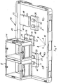
Fig. 1 eine perspektivische Draufsicht auf ein Tablar mit aufgenommenen Behältern, -
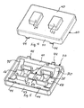
Fig. 2 eine perspektivische Draufsicht auf eine erste nicht beanspruchte Ausführungsform eines Stützteils, -
Fig. 3 eine perspektivische Draufsicht auf eine zweite Ausführungsform eines Stützteil, -
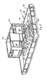
Fig. 4 eine perspektivische Draufsicht auf eine dritte Ausführungsform eines Stützteils, -
Fig. 5 eine perspektivische Unteransicht des Stützteils vonFig. 4 . -
Fig. 6 eine weitere perspektivische Draufsicht auf das Tablar vonFig. 1 mit aufgenommenen Behältern, wobei ein Behälter im Schnitt gezeigt ist. - Das in
Fig. 1 gezeigte Tablar 10 umfasst eine rechteckige Bodenwand 14 von der sich ein umlaufender Rand 12 senkrecht nach oben erstreckt. Auf der Bodenwand 14 sind mehrere Stützteile 18, 20, 22 an vorherbestimmten Stellen angeordnet. Die Stützteile 18, 20, 22 weisen jeweils eine parallel zur Bodenwand 14 im Abstand verlaufende Stützfläche 40 auf, von deren Umfang sich ein Umfangsrand 42 senkrecht nach unten erstreckt. Wie es in denFig. 2 bis 5 gezeigt ist, erstrecken sich von dem unteren Rand der beiden gegenüberliegenden Längsseiten 41, 43 des Umfangsrandes 42 jeweils zwei Rastzungen 44 nach unten. Die vier Rastzungen 44 sind an den Ecken eines gedachten Rechtecks angeordnet. WieFig. 2 zeigt, weist jede Rastzunge 44 einen sich bündig zum Umfangsrand 42 nach unten erstreckenden Steg 46 auf, von dessen unteren Rand sich ein Schenkel 48 senkrecht nach außen erstreckt. - In der Bodenwand 14 des Tablars 10 sind an vorherbestimmten Stellen Rastschlitze 16 in einem vorherbestimmten Muster ausgebildet. Die Rastschlitze 16 sind dabei so angeordnet, dass ein Stützteil 18, 20,22 mit seinen Rastzungen 44 jeweils in einen Satz von vier Rastschlitzen 16 eingesetzt werden kann. Die Rastschlitze 16 weisen einen breiteren Abschnitt 16b auf, an den sich ein Abschnitt 16a mit geringerer Breite anschließt. Zur Befestigung werden die Stützteile 18, 20, 22 mit den Rastzungen 44 jeweils in den breiteren Abschnitt 16b eingesetzt, dessen Breite größer ist, als die Breite der Schenkel 48. Anschließend werden die Stützteile 18, 20, 22 in Richtung des Abschnitts 16a mit kleinerer Breite geschoben, dessen Breite im Wesentlichen der Breite des Steges 46 entspricht. Hierdurch hintergreifen die Stege 48 die Bodenwand 14 und liegen an der unteren Seite der Bodenwand 14 an, während der Umfangsrand 42 auf der oberen Seite der Bodenwand 14 aufliegt. Durch diese Schiebeverriegelung wird ein formschlüssiger Eingriff der Stützteile 18, 20, 22 geschaffen. Gleichzeitig dienen die Rastschlitze 16 als Wasserablauflöcher.
- Das in
Fig. 2 gezeigte Stützteil 18 weist eine durchgehende Stützfläche 40 auf. Der Abstand der Stützfläche 40 zur Bodenwand 14 ist so bemessen dass die Stützfläche 40 an der Unterseite eines auf das Tablar 10 aufgestellten größeren Behälters anliegt und diesen abstützt. - Bei dem in
Fig. 3 gezeigten Stützteil 22 sind zwei im Wesentlichen quaderförmige Anschlagvorsprünge 28, 30 einstückig angeformt und erstrecken sich von der Stützfläche 40 nach oben. Die Anschlagvorsprünge 28, 30 sind so angeordnet, dass sie zwischen Stapelränder 80 benachbarter kleinerer Behälter 32, 34 (Fig. 6 ) eingreifen können, um die aufgesetzten Behälter 32, 34 zu fixieren, damit ein Verrutschen verhindert wird. - Das Stützteil 20 in
Fig. 4 und Fig. 5 unterscheidet sich von dem Stützteil 22 inFig. 3 dadurch, dass die Anschlagvorsprünge 24, 26 nicht fest an dem Stützteil angeformt sind, sondern durch die Stützfläche 40 hindurchgehen und senkrecht zur Stützfläche 40 bewegbar sind. Hierzu sind die Anschlagvorsprünge 24, 26 in sich von der Unterseite der Stützfläche 40 nach unten erstreckenden Führungen 62 geführt. Die unteren Ränder der Anschlagvorsprünge 24, 26 sind durch einen parallel zu den Längsseiten des Stützteils 20 verlaufenden Mittelsteg 64 verbunden. Dem Mittelsteg 62 gegenüberliegend erstreckt sich jeweils ein Fortsatz 66, 68 von dem unteren Rand der Anschlagsvorsprünge 24, 26 nach außen. Der Mittelsteg 64 und die Fortsätze 66, 68 sind in nach unten offenen Schlitzen in den Führungen 62 geführt. An den Fortsätzen 66, 68 sind außerhalb der Führungen 62 bogenförmige Federzungen 70 senkrecht zu den Fortsätzen 66, 68 angeformt. Wenn das Stützteil 20 in die Bodenwand 14 eingesetzt ist, berühren die Federzungen 70 mit ihren beiden Enden die Bodenwand 14 und sind nach oben gekrümmt. Wenn die Anschlagvorsprünge 24, 26 unbelastet sind, berühren die Fortsätze 66, 68 sowie der Mittelsteg 64 die Unterseite der Stützfläche 40. Wenn dagegen ein Druck auf die Oberseite der Anschlagvorsprünge 24, 26 ausgeübt wird, werden diese gegen die Vorspannung der Federzungen 70 nach unten bewegt, bis die obere Oberfläche der Anschlagvorsprünge 24, 26 bündig zur Stützfläche 40 sind. Das Stützteil 20 erfüllt somit die Funktion des Stützteils 18 und des Stützteils 22, ohne jedoch speziell an die Art des Behälters angepasst sein zu müssen.
Claims (4)
- Tablar zur Aufnahme von Behältern (32, 34), das eine Bodenwand (14) umfasst, auf der wenigstens ein Stützteil (18, 20, 22) an wenigstens einer vorher bestimmten Stelle lösbar befestigt ist, das eine parallel zur Bodenwand (14) verlaufende Stützfläche (40) aufweist, wobei der Abstand der Stützfläche (40) von der Bodenwand (14) der Höhendifferenz zwischen der Bodenwand (14) und einem Behälterboden entspricht, dadurch gekennzeichnet, dass von der Stützfläche (40) Anschlagvorsprünge (24, 26, 28, 30) nach oben vorstehen, die so angeordnet sind, dass sie zwischen benachbarte Stapelränder (80) nebeneinander angeordneter Behälter (32, 34) eingreifen können.
- Tablar nach Anspruch 1, dadurch gekennzeichnet, dass die Anschlagvorsprünge (24, 26) durch die Stützfläche (40) hindurchgehen und senkrecht zur Stützfläche (40) bewegbar sind, wobei eine Vorspanneinrichtung (70) innerhalb des Stützteils (20) vorgesehen ist, gegen deren Vorspannkraft die Anschlagvorsprünge (24, 26) aus einer Anschlagstellung in der sie nach oben über die Stützfläche (40) vorstehen, in eine Absenkstellung bewegt werden können, in der ihre Oberseite bündig zur Stützfläche (40) ist.
- Tablar nach einem der vorhergehenden Ansprüche, dadurch gekennzeichnet, dass in der Bodenwand (14) Rastschlitze (16) in einem vorgegebenen Muster ausgebildet sind, in die sich von dem Stützteil (18, 20, 22) nach unten erstreckende Rastzungen (44) zur lösbaren Befestigung des Stützteils (18, 20, 22) eingreifen.
- Tablar nach Anspruch 3, dadurch gekennzeichnet, dass die Rastöffnungen (16) so ausgebildet sind, dass nach Befestigung eines Stützteils (18, 20, 22) ein Wasserablauf gewährleistet ist.
Priority Applications (4)
| Application Number | Priority Date | Filing Date | Title |
|---|---|---|---|
| AT05023747T ATE406323T1 (de) | 2005-10-31 | 2005-10-31 | Tablar zur aufnahme von behältern |
| ES05023747T ES2311916T3 (es) | 2005-10-31 | 2005-10-31 | Tablero para el alojamiento de contenedores. |
| EP05023747A EP1780144B1 (de) | 2005-10-31 | 2005-10-31 | Tablar zur Aufnahme von Behältern |
| DE502005005209T DE502005005209D1 (de) | 2005-10-31 | 2005-10-31 | Tablar zur Aufnahme von Behältern |
Applications Claiming Priority (1)
| Application Number | Priority Date | Filing Date | Title |
|---|---|---|---|
| EP05023747A EP1780144B1 (de) | 2005-10-31 | 2005-10-31 | Tablar zur Aufnahme von Behältern |
Publications (2)
| Publication Number | Publication Date |
|---|---|
| EP1780144A1 EP1780144A1 (de) | 2007-05-02 |
| EP1780144B1 true EP1780144B1 (de) | 2008-08-27 |
Family
ID=36123320
Family Applications (1)
| Application Number | Title | Priority Date | Filing Date |
|---|---|---|---|
| EP05023747A Expired - Lifetime EP1780144B1 (de) | 2005-10-31 | 2005-10-31 | Tablar zur Aufnahme von Behältern |
Country Status (4)
| Country | Link |
|---|---|
| EP (1) | EP1780144B1 (de) |
| AT (1) | ATE406323T1 (de) |
| DE (1) | DE502005005209D1 (de) |
| ES (1) | ES2311916T3 (de) |
Families Citing this family (1)
| Publication number | Priority date | Publication date | Assignee | Title |
|---|---|---|---|---|
| DE202016100079U1 (de) * | 2016-01-11 | 2017-04-12 | bekuplast Gesellschaft mit beschränkter Haftung | Träger zum Lagern und Transportieren von Behältern |
Family Cites Families (3)
| Publication number | Priority date | Publication date | Assignee | Title |
|---|---|---|---|---|
| DE9214010U1 (de) * | 1992-10-19 | 1992-12-03 | Haus Dieck Design GmbH, 59320 Ennigerloh | Ablageschale |
| DE29814925U1 (de) * | 1998-08-20 | 1998-11-05 | Georg Utz Holding Ag, Bremgarten | Tray zum Einsatz insbesondere in automatischen Lagern |
| DE29819420U1 (de) * | 1998-10-30 | 1999-04-15 | Fritz Schäfer GmbH, 57290 Neunkirchen | Tablar o.dgl. Tragmittel |
-
2005
- 2005-10-31 EP EP05023747A patent/EP1780144B1/de not_active Expired - Lifetime
- 2005-10-31 AT AT05023747T patent/ATE406323T1/de active
- 2005-10-31 DE DE502005005209T patent/DE502005005209D1/de not_active Expired - Lifetime
- 2005-10-31 ES ES05023747T patent/ES2311916T3/es not_active Expired - Lifetime
Also Published As
| Publication number | Publication date |
|---|---|
| ES2311916T3 (es) | 2009-02-16 |
| DE502005005209D1 (de) | 2008-10-09 |
| ATE406323T1 (de) | 2008-09-15 |
| EP1780144A1 (de) | 2007-05-02 |
Similar Documents
| Publication | Publication Date | Title |
|---|---|---|
| EP3772247B1 (de) | Substratmagazin, substratmagazinsystem und substratbestückungsanlage | |
| DE3836553C2 (de) | Plattenträger | |
| DE20108895U1 (de) | Kastenmodul für Gegenstände | |
| DE102009014133A1 (de) | Befestigungsclip und dazugehörige Befestigungsvorrichtung | |
| EP0011819B1 (de) | Hefterelement | |
| EP2559628A1 (de) | Stapelbarer behälter sowie Behälteranordnung mit mehreren solchen Behältern | |
| DE1586624A1 (de) | Zusammenklappbarer Transportkasten | |
| EP3855571A1 (de) | Anschlussklemme und elektronisches gerät | |
| DE1927066C3 (de) | Führungsteil für gedruckte Schaltungsplatten | |
| EP1780144A1 (de) | Tablar zur Aufnahme von Behältern | |
| EP1532409A1 (de) | Absteller für ein kältegerät | |
| EP1439067B1 (de) | Verfahren zum Einsetzen einer Trägerplatine in eine Haltevorrichtung an einer Patrone oder Kartusche sowie Haltevorrichtung hierzu | |
| EP1124298B1 (de) | Unterflurgerätedose | |
| DE69510627T2 (de) | Geräteträgereinrichtung Einzubringen auf einen Kabelkanalkörper | |
| EP4181734B1 (de) | Adaptereinheit zur verbindung eines schubkastenbodens mit einer seitenzarge eines schubkastens, seitenzarge und schubkasten | |
| WO2005097608A1 (de) | Lagerbox | |
| DE10234788B4 (de) | Vorrichtung zur planparallelen Befestigung zwei Module | |
| DE2110046C2 (de) | Bodenteil eines Lochers für Schriftgut | |
| DE19710625C2 (de) | Kunststoffkettenglied einer Energieführungskette | |
| DE3703806C2 (de) | Aus stapelbaren Trägerplatten bestehende Werkstück-Träger-Vorrichtung | |
| EP1319603B1 (de) | Schachtelartiger Behälter | |
| DE102019110836A1 (de) | Transportbehälter | |
| AT519700B1 (de) | Verpackung | |
| DE29808713U1 (de) | Abheftvorrichtung | |
| DE9408233U1 (de) | Behälter oder Einsatz für Behälter |
Legal Events
| Date | Code | Title | Description |
|---|---|---|---|
| PUAI | Public reference made under article 153(3) epc to a published international application that has entered the european phase |
Free format text: ORIGINAL CODE: 0009012 |
|
| AK | Designated contracting states |
Kind code of ref document: A1 Designated state(s): AT BE BG CH CY CZ DE DK EE ES FI FR GB GR HU IE IS IT LI LT LU LV MC NL PL PT RO SE SI SK TR |
|
| AX | Request for extension of the european patent |
Extension state: AL BA HR MK YU |
|
| 17P | Request for examination filed |
Effective date: 20070924 |
|
| AKX | Designation fees paid |
Designated state(s): AT BE BG CH CY CZ DE DK EE ES FI FR GB GR HU IE IS IT LI LT LU LV MC NL PL PT RO SE SI SK TR |
|
| GRAP | Despatch of communication of intention to grant a patent |
Free format text: ORIGINAL CODE: EPIDOSNIGR1 |
|
| RIN1 | Information on inventor provided before grant (corrected) |
Inventor name: MATTES, ANDREAS |
|
| RIN1 | Information on inventor provided before grant (corrected) |
Inventor name: MATTES, ANDREAS |
|
| GRAS | Grant fee paid |
Free format text: ORIGINAL CODE: EPIDOSNIGR3 |
|
| GRAA | (expected) grant |
Free format text: ORIGINAL CODE: 0009210 |
|
| AK | Designated contracting states |
Kind code of ref document: B1 Designated state(s): AT BE BG CH CY CZ DE DK EE ES FI FR GB GR HU IE IS IT LI LT LU LV MC NL PL PT RO SE SI SK TR |
|
| REG | Reference to a national code |
Ref country code: GB Ref legal event code: FG4D Free format text: NOT ENGLISH |
|
| REG | Reference to a national code |
Ref country code: CH Ref legal event code: NV Representative=s name: ING. MARCO ZARDI C/O M. ZARDI & CO. S.A. Ref country code: CH Ref legal event code: EP |
|
| REG | Reference to a national code |
Ref country code: IE Ref legal event code: FG4D Free format text: LANGUAGE OF EP DOCUMENT: GERMAN |
|
| REF | Corresponds to: |
Ref document number: 502005005209 Country of ref document: DE Date of ref document: 20081009 Kind code of ref document: P |
|
| PG25 | Lapsed in a contracting state [announced via postgrant information from national office to epo] |
Ref country code: IS Free format text: LAPSE BECAUSE OF FAILURE TO SUBMIT A TRANSLATION OF THE DESCRIPTION OR TO PAY THE FEE WITHIN THE PRESCRIBED TIME-LIMIT Effective date: 20081227 Ref country code: LT Free format text: LAPSE BECAUSE OF FAILURE TO SUBMIT A TRANSLATION OF THE DESCRIPTION OR TO PAY THE FEE WITHIN THE PRESCRIBED TIME-LIMIT Effective date: 20080827 |
|
| REG | Reference to a national code |
Ref country code: ES Ref legal event code: FG2A Ref document number: 2311916 Country of ref document: ES Kind code of ref document: T3 |
|
| PG25 | Lapsed in a contracting state [announced via postgrant information from national office to epo] |
Ref country code: FI Free format text: LAPSE BECAUSE OF FAILURE TO SUBMIT A TRANSLATION OF THE DESCRIPTION OR TO PAY THE FEE WITHIN THE PRESCRIBED TIME-LIMIT Effective date: 20080827 Ref country code: SI Free format text: LAPSE BECAUSE OF FAILURE TO SUBMIT A TRANSLATION OF THE DESCRIPTION OR TO PAY THE FEE WITHIN THE PRESCRIBED TIME-LIMIT Effective date: 20080827 Ref country code: LV Free format text: LAPSE BECAUSE OF FAILURE TO SUBMIT A TRANSLATION OF THE DESCRIPTION OR TO PAY THE FEE WITHIN THE PRESCRIBED TIME-LIMIT Effective date: 20080827 |
|
| REG | Reference to a national code |
Ref country code: IE Ref legal event code: FD4D |
|
| BERE | Be: lapsed |
Owner name: BITO-LAGERTECHNIK BITTMANN G.M.B.H. Effective date: 20081031 |
|
| PG25 | Lapsed in a contracting state [announced via postgrant information from national office to epo] |
Ref country code: IE Free format text: LAPSE BECAUSE OF FAILURE TO SUBMIT A TRANSLATION OF THE DESCRIPTION OR TO PAY THE FEE WITHIN THE PRESCRIBED TIME-LIMIT Effective date: 20080827 Ref country code: BG Free format text: LAPSE BECAUSE OF FAILURE TO SUBMIT A TRANSLATION OF THE DESCRIPTION OR TO PAY THE FEE WITHIN THE PRESCRIBED TIME-LIMIT Effective date: 20081127 Ref country code: DK Free format text: LAPSE BECAUSE OF FAILURE TO SUBMIT A TRANSLATION OF THE DESCRIPTION OR TO PAY THE FEE WITHIN THE PRESCRIBED TIME-LIMIT Effective date: 20080827 |
|
| PG25 | Lapsed in a contracting state [announced via postgrant information from national office to epo] |
Ref country code: CZ Free format text: LAPSE BECAUSE OF FAILURE TO SUBMIT A TRANSLATION OF THE DESCRIPTION OR TO PAY THE FEE WITHIN THE PRESCRIBED TIME-LIMIT Effective date: 20080827 Ref country code: MC Free format text: LAPSE BECAUSE OF NON-PAYMENT OF DUE FEES Effective date: 20081031 Ref country code: PT Free format text: LAPSE BECAUSE OF FAILURE TO SUBMIT A TRANSLATION OF THE DESCRIPTION OR TO PAY THE FEE WITHIN THE PRESCRIBED TIME-LIMIT Effective date: 20090127 Ref country code: RO Free format text: LAPSE BECAUSE OF FAILURE TO SUBMIT A TRANSLATION OF THE DESCRIPTION OR TO PAY THE FEE WITHIN THE PRESCRIBED TIME-LIMIT Effective date: 20080827 Ref country code: SK Free format text: LAPSE BECAUSE OF FAILURE TO SUBMIT A TRANSLATION OF THE DESCRIPTION OR TO PAY THE FEE WITHIN THE PRESCRIBED TIME-LIMIT Effective date: 20080827 |
|
| PLBE | No opposition filed within time limit |
Free format text: ORIGINAL CODE: 0009261 |
|
| STAA | Information on the status of an ep patent application or granted ep patent |
Free format text: STATUS: NO OPPOSITION FILED WITHIN TIME LIMIT |
|
| PG25 | Lapsed in a contracting state [announced via postgrant information from national office to epo] |
Ref country code: EE Free format text: LAPSE BECAUSE OF FAILURE TO SUBMIT A TRANSLATION OF THE DESCRIPTION OR TO PAY THE FEE WITHIN THE PRESCRIBED TIME-LIMIT Effective date: 20080827 |
|
| 26N | No opposition filed |
Effective date: 20090528 |
|
| PG25 | Lapsed in a contracting state [announced via postgrant information from national office to epo] |
Ref country code: BE Free format text: LAPSE BECAUSE OF NON-PAYMENT OF DUE FEES Effective date: 20081031 |
|
| PG25 | Lapsed in a contracting state [announced via postgrant information from national office to epo] |
Ref country code: SE Free format text: LAPSE BECAUSE OF FAILURE TO SUBMIT A TRANSLATION OF THE DESCRIPTION OR TO PAY THE FEE WITHIN THE PRESCRIBED TIME-LIMIT Effective date: 20081127 |
|
| PG25 | Lapsed in a contracting state [announced via postgrant information from national office to epo] |
Ref country code: PL Free format text: LAPSE BECAUSE OF FAILURE TO SUBMIT A TRANSLATION OF THE DESCRIPTION OR TO PAY THE FEE WITHIN THE PRESCRIBED TIME-LIMIT Effective date: 20080827 |
|
| PG25 | Lapsed in a contracting state [announced via postgrant information from national office to epo] |
Ref country code: CY Free format text: LAPSE BECAUSE OF FAILURE TO SUBMIT A TRANSLATION OF THE DESCRIPTION OR TO PAY THE FEE WITHIN THE PRESCRIBED TIME-LIMIT Effective date: 20080827 Ref country code: LU Free format text: LAPSE BECAUSE OF NON-PAYMENT OF DUE FEES Effective date: 20081031 Ref country code: HU Free format text: LAPSE BECAUSE OF FAILURE TO SUBMIT A TRANSLATION OF THE DESCRIPTION OR TO PAY THE FEE WITHIN THE PRESCRIBED TIME-LIMIT Effective date: 20090228 |
|
| PG25 | Lapsed in a contracting state [announced via postgrant information from national office to epo] |
Ref country code: TR Free format text: LAPSE BECAUSE OF FAILURE TO SUBMIT A TRANSLATION OF THE DESCRIPTION OR TO PAY THE FEE WITHIN THE PRESCRIBED TIME-LIMIT Effective date: 20080827 |
|
| PG25 | Lapsed in a contracting state [announced via postgrant information from national office to epo] |
Ref country code: GR Free format text: LAPSE BECAUSE OF FAILURE TO SUBMIT A TRANSLATION OF THE DESCRIPTION OR TO PAY THE FEE WITHIN THE PRESCRIBED TIME-LIMIT Effective date: 20081128 |
|
| PGFP | Annual fee paid to national office [announced via postgrant information from national office to epo] |
Ref country code: AT Payment date: 20131011 Year of fee payment: 9 |
|
| PGFP | Annual fee paid to national office [announced via postgrant information from national office to epo] |
Ref country code: NL Payment date: 20131022 Year of fee payment: 9 |
|
| REG | Reference to a national code |
Ref country code: NL Ref legal event code: V1 Effective date: 20150501 |
|
| REG | Reference to a national code |
Ref country code: AT Ref legal event code: MM01 Ref document number: 406323 Country of ref document: AT Kind code of ref document: T Effective date: 20141031 |
|
| PG25 | Lapsed in a contracting state [announced via postgrant information from national office to epo] |
Ref country code: AT Free format text: LAPSE BECAUSE OF NON-PAYMENT OF DUE FEES Effective date: 20141031 Ref country code: NL Free format text: LAPSE BECAUSE OF NON-PAYMENT OF DUE FEES Effective date: 20150501 |
|
| REG | Reference to a national code |
Ref country code: FR Ref legal event code: PLFP Year of fee payment: 11 |
|
| REG | Reference to a national code |
Ref country code: FR Ref legal event code: PLFP Year of fee payment: 12 |
|
| REG | Reference to a national code |
Ref country code: FR Ref legal event code: PLFP Year of fee payment: 13 |
|
| PGFP | Annual fee paid to national office [announced via postgrant information from national office to epo] |
Ref country code: FR Payment date: 20171024 Year of fee payment: 13 Ref country code: DE Payment date: 20171019 Year of fee payment: 13 |
|
| PGFP | Annual fee paid to national office [announced via postgrant information from national office to epo] |
Ref country code: IT Payment date: 20171023 Year of fee payment: 13 Ref country code: CH Payment date: 20171019 Year of fee payment: 13 Ref country code: GB Payment date: 20171019 Year of fee payment: 13 Ref country code: ES Payment date: 20171121 Year of fee payment: 13 |
|
| REG | Reference to a national code |
Ref country code: DE Ref legal event code: R119 Ref document number: 502005005209 Country of ref document: DE |
|
| REG | Reference to a national code |
Ref country code: CH Ref legal event code: PL |
|
| GBPC | Gb: european patent ceased through non-payment of renewal fee |
Effective date: 20181031 |
|
| PG25 | Lapsed in a contracting state [announced via postgrant information from national office to epo] |
Ref country code: DE Free format text: LAPSE BECAUSE OF NON-PAYMENT OF DUE FEES Effective date: 20190501 |
|
| PG25 | Lapsed in a contracting state [announced via postgrant information from national office to epo] |
Ref country code: CH Free format text: LAPSE BECAUSE OF NON-PAYMENT OF DUE FEES Effective date: 20181031 Ref country code: LI Free format text: LAPSE BECAUSE OF NON-PAYMENT OF DUE FEES Effective date: 20181031 Ref country code: FR Free format text: LAPSE BECAUSE OF NON-PAYMENT OF DUE FEES Effective date: 20181031 |
|
| PG25 | Lapsed in a contracting state [announced via postgrant information from national office to epo] |
Ref country code: GB Free format text: LAPSE BECAUSE OF NON-PAYMENT OF DUE FEES Effective date: 20181031 Ref country code: IT Free format text: LAPSE BECAUSE OF NON-PAYMENT OF DUE FEES Effective date: 20181031 |
|
| REG | Reference to a national code |
Ref country code: ES Ref legal event code: FD2A Effective date: 20191204 |
|
| PG25 | Lapsed in a contracting state [announced via postgrant information from national office to epo] |
Ref country code: ES Free format text: LAPSE BECAUSE OF NON-PAYMENT OF DUE FEES Effective date: 20181101 |