EP1777452B2 - Beheizbarer Steckverbinder - Google Patents
Beheizbarer Steckverbinder Download PDFInfo
- Publication number
- EP1777452B2 EP1777452B2 EP06022243.7A EP06022243A EP1777452B2 EP 1777452 B2 EP1777452 B2 EP 1777452B2 EP 06022243 A EP06022243 A EP 06022243A EP 1777452 B2 EP1777452 B2 EP 1777452B2
- Authority
- EP
- European Patent Office
- Prior art keywords
- plug connector
- connector
- heating element
- heating
- fluid line
- Prior art date
- Legal status (The legal status is an assumption and is not a legal conclusion. Google has not performed a legal analysis and makes no representation as to the accuracy of the status listed.)
- Active
Links
- 238000010438 heat treatment Methods 0.000 claims abstract description 119
- 239000012530 fluid Substances 0.000 claims abstract description 73
- 239000007788 liquid Substances 0.000 claims abstract description 7
- 229910001220 stainless steel Inorganic materials 0.000 claims abstract description 7
- 239000010935 stainless steel Substances 0.000 claims abstract description 7
- 230000013011 mating Effects 0.000 claims description 46
- 210000002105 tongue Anatomy 0.000 claims description 16
- 239000004020 conductor Substances 0.000 claims description 6
- 229910052751 metal Inorganic materials 0.000 claims description 4
- 239000002184 metal Substances 0.000 claims description 4
- RYGMFSIKBFXOCR-UHFFFAOYSA-N Copper Chemical compound [Cu] RYGMFSIKBFXOCR-UHFFFAOYSA-N 0.000 claims description 3
- 229910052782 aluminium Inorganic materials 0.000 claims description 3
- XAGFODPZIPBFFR-UHFFFAOYSA-N aluminium Chemical compound [Al] XAGFODPZIPBFFR-UHFFFAOYSA-N 0.000 claims description 3
- 229910052802 copper Inorganic materials 0.000 claims description 3
- 239000010949 copper Substances 0.000 claims description 3
- 238000003780 insertion Methods 0.000 claims description 3
- 230000037431 insertion Effects 0.000 claims description 3
- 239000012777 electrically insulating material Substances 0.000 claims description 2
- 239000004411 aluminium Substances 0.000 claims 1
- 239000003251 chemically resistant material Substances 0.000 claims 1
- XSQUKJJJFZCRTK-UHFFFAOYSA-N Urea Chemical compound NC(N)=O XSQUKJJJFZCRTK-UHFFFAOYSA-N 0.000 description 3
- 239000004202 carbamide Substances 0.000 description 3
- 238000004140 cleaning Methods 0.000 description 2
- 230000008014 freezing Effects 0.000 description 2
- 238000007710 freezing Methods 0.000 description 2
- 239000000463 material Substances 0.000 description 2
- 239000000126 substance Substances 0.000 description 2
- 230000015572 biosynthetic process Effects 0.000 description 1
- 239000011248 coating agent Substances 0.000 description 1
- 238000000576 coating method Methods 0.000 description 1
- 230000001419 dependent effect Effects 0.000 description 1
- 238000011161 development Methods 0.000 description 1
- 230000018109 developmental process Effects 0.000 description 1
- 238000010292 electrical insulation Methods 0.000 description 1
- 239000000446 fuel Substances 0.000 description 1
- 239000011810 insulating material Substances 0.000 description 1
- 238000009413 insulation Methods 0.000 description 1
- 230000000284 resting effect Effects 0.000 description 1
- 238000000926 separation method Methods 0.000 description 1
Images


Classifications
-
- F—MECHANICAL ENGINEERING; LIGHTING; HEATING; WEAPONS; BLASTING
- F16—ENGINEERING ELEMENTS AND UNITS; GENERAL MEASURES FOR PRODUCING AND MAINTAINING EFFECTIVE FUNCTIONING OF MACHINES OR INSTALLATIONS; THERMAL INSULATION IN GENERAL
- F16L—PIPES; JOINTS OR FITTINGS FOR PIPES; SUPPORTS FOR PIPES, CABLES OR PROTECTIVE TUBING; MEANS FOR THERMAL INSULATION IN GENERAL
- F16L53/00—Heating of pipes or pipe systems; Cooling of pipes or pipe systems
- F16L53/30—Heating of pipes or pipe systems
- F16L53/35—Ohmic-resistance heating
-
- F—MECHANICAL ENGINEERING; LIGHTING; HEATING; WEAPONS; BLASTING
- F01—MACHINES OR ENGINES IN GENERAL; ENGINE PLANTS IN GENERAL; STEAM ENGINES
- F01N—GAS-FLOW SILENCERS OR EXHAUST APPARATUS FOR MACHINES OR ENGINES IN GENERAL; GAS-FLOW SILENCERS OR EXHAUST APPARATUS FOR INTERNAL COMBUSTION ENGINES
- F01N2610/00—Adding substances to exhaust gases
- F01N2610/02—Adding substances to exhaust gases the substance being ammonia or urea
-
- F—MECHANICAL ENGINEERING; LIGHTING; HEATING; WEAPONS; BLASTING
- F01—MACHINES OR ENGINES IN GENERAL; ENGINE PLANTS IN GENERAL; STEAM ENGINES
- F01N—GAS-FLOW SILENCERS OR EXHAUST APPARATUS FOR MACHINES OR ENGINES IN GENERAL; GAS-FLOW SILENCERS OR EXHAUST APPARATUS FOR INTERNAL COMBUSTION ENGINES
- F01N2610/00—Adding substances to exhaust gases
- F01N2610/10—Adding substances to exhaust gases the substance being heated, e.g. by heating tank or supply line of the added substance
-
- F—MECHANICAL ENGINEERING; LIGHTING; HEATING; WEAPONS; BLASTING
- F01—MACHINES OR ENGINES IN GENERAL; ENGINE PLANTS IN GENERAL; STEAM ENGINES
- F01N—GAS-FLOW SILENCERS OR EXHAUST APPARATUS FOR MACHINES OR ENGINES IN GENERAL; GAS-FLOW SILENCERS OR EXHAUST APPARATUS FOR INTERNAL COMBUSTION ENGINES
- F01N2610/00—Adding substances to exhaust gases
- F01N2610/14—Arrangements for the supply of substances, e.g. conduits
- F01N2610/1486—Means to prevent the substance from freezing
-
- F—MECHANICAL ENGINEERING; LIGHTING; HEATING; WEAPONS; BLASTING
- F01—MACHINES OR ENGINES IN GENERAL; ENGINE PLANTS IN GENERAL; STEAM ENGINES
- F01N—GAS-FLOW SILENCERS OR EXHAUST APPARATUS FOR MACHINES OR ENGINES IN GENERAL; GAS-FLOW SILENCERS OR EXHAUST APPARATUS FOR INTERNAL COMBUSTION ENGINES
- F01N3/00—Exhaust or silencing apparatus having means for purifying, rendering innocuous, or otherwise treating exhaust
- F01N3/08—Exhaust or silencing apparatus having means for purifying, rendering innocuous, or otherwise treating exhaust for rendering innocuous
- F01N3/10—Exhaust or silencing apparatus having means for purifying, rendering innocuous, or otherwise treating exhaust for rendering innocuous by thermal or catalytic conversion of noxious components of exhaust
- F01N3/18—Exhaust or silencing apparatus having means for purifying, rendering innocuous, or otherwise treating exhaust for rendering innocuous by thermal or catalytic conversion of noxious components of exhaust characterised by methods of operation; Control
- F01N3/20—Exhaust or silencing apparatus having means for purifying, rendering innocuous, or otherwise treating exhaust for rendering innocuous by thermal or catalytic conversion of noxious components of exhaust characterised by methods of operation; Control specially adapted for catalytic conversion ; Methods of operation or control of catalytic converters
- F01N3/2066—Selective catalytic reduction [SCR]
-
- H—ELECTRICITY
- H01—ELECTRIC ELEMENTS
- H01R—ELECTRICALLY-CONDUCTIVE CONNECTIONS; STRUCTURAL ASSOCIATIONS OF A PLURALITY OF MUTUALLY-INSULATED ELECTRICAL CONNECTING ELEMENTS; COUPLING DEVICES; CURRENT COLLECTORS
- H01R13/00—Details of coupling devices of the kinds covered by groups H01R12/70 or H01R24/00 - H01R33/00
- H01R13/005—Electrical coupling combined with fluidic coupling
-
- Y—GENERAL TAGGING OF NEW TECHNOLOGICAL DEVELOPMENTS; GENERAL TAGGING OF CROSS-SECTIONAL TECHNOLOGIES SPANNING OVER SEVERAL SECTIONS OF THE IPC; TECHNICAL SUBJECTS COVERED BY FORMER USPC CROSS-REFERENCE ART COLLECTIONS [XRACs] AND DIGESTS
- Y02—TECHNOLOGIES OR APPLICATIONS FOR MITIGATION OR ADAPTATION AGAINST CLIMATE CHANGE
- Y02A—TECHNOLOGIES FOR ADAPTATION TO CLIMATE CHANGE
- Y02A50/00—TECHNOLOGIES FOR ADAPTATION TO CLIMATE CHANGE in human health protection, e.g. against extreme weather
- Y02A50/20—Air quality improvement or preservation, e.g. vehicle emission control or emission reduction by using catalytic converters
Definitions
- the present invention relates to a connector for connecting a first fluid line to a second fluid line in cooperation with at least one mating connector, a medium flowing between the first fluid line and the second fluid line through the connector.
- Such plug connectors are installed, for example, in motor vehicles, in particular in the conveyor chain for aqueous urea solutions, fuels, blow-by gas, or cleaning fluids for cleaning windows or headlights.
- the liquid contained in the conveyor chain or the moisture contained in the gas can freeze at low temperatures and ice can form. Therefore, in known arrangements, the elements of the conveyor chain that convey these fluids, such as pumps or hoses, are heated in order to prevent them from freezing.
- the pending European patent application EP 1 557 601 A1 the applicant describes a heating clip for a fluid line, which comprises a heating element arranged in a housing and which is designed to be clipped to the fluid line.
- a heating clip can be clipped onto the fluid line from the outside and can be arranged at any point along the fluid line.
- such a heating clip is not adapted to heat a medium to be heated at the interface between two fluid lines.
- connection of heated hoses for example with unheated sleeves
- connection of heated hoses via an unheated connection piece is described in this document, with the heating conductors of the heated hoses being used in part to heat the connection piece.
- the ends of the heating conductors resting on the connecting piece are connected and led to the outside with a common connection element.
- the connecting element, heating conductor and end of the hose are overmoulded with a coating of insulating material and form a non-detachable block element.
- the EP 1 375 997 A1 shows a connector for connecting a first fluid line to a second fluid line.
- a medium to be heated flows between the first fluid line and the second fluid line through the metal connector.
- the connector has a heating element for heating the medium to be heated, which is arranged in a lateral recess of the tubular connector.
- a holding device made of plastic is provided for mounting and electrical connection of the heating element.
- the invention is therefore based on the object of improving a connector of the type mentioned in such a way that freezing of a fluid flowing through the connector can also be prevented in the connector.
- the connector includes at least one heating element for heating the medium to be heated, the liquid flowing through the connector is heated and possible ice build-up can be prevented.
- the heating element is enclosed in a housing part of the connector, which is sealed from the medium to be heated. This guarantees that the medium to be heated and the heating area in which the heating element is located are fluidically and electrically separated from one another. This enables good electrical insulation between the heating area and the medium to be heated flowing through the connector. In addition, the separation of the functional areas "flow through” and “heating” achieves a secure seal against fluid passing through.
- the housing part comprises a duct formed in the housing, and the at least one heating element is inserted in the duct.
- the connector includes a flow channel through which the medium to be heated flows, with the at least one heating element being sealed off by the flow channel, it can be ensured that the heating area, in which the at least one heating element is located, and the medium to be heated are hermetically sealed from one another are isolated.
- the first fluid line comprises a first tube, which is provided with a first mating connector, and the connector can be connected to the first mating connector, a quick connection between the first fluid line and the connector can be established in a simple manner.
- the first fluid line comprises two hoses, each provided with a first mating connector, and the connector is connectable to each first mating connector, the first fluid line is connected to the connector by two quick connectors, thus forming a T-junction.
- the connector includes a fluid connection element for connecting the second fluid line to the connector, wherein the second fluid line includes a second hose, and the fluid connection element is tubular, so that the second hose can be placed on the fluid connection element, the second fluid line can be easily attached to the connectors are connected.
- the fluid connection element is provided with projections for holding the attached second tube to ensure a secure contact between the To ensure connector and the second fluid line.
- the second fluid line comprises a second tube that is provided with a second mating connector, and the connector is connectable to the second mating connector.
- the first and second fluid lines can be connected to the connector by quick connections.
- the first fluid line comprises two hoses connected to the connector by two quick connectors and the second fluid line is also connected to the connector by a quick connector, a T-junction is formed with three fluid lines connected to the connector with a maximum of three quick connectors .
- the connector is provided with a heating lance, which consists of a thermally conductive material, preferably copper, aluminum or stainless steel, and is thermally conductively connected to the at least one heating element, the heat generated by the at least one heating element can be transferred to the thermally conductive heating lance in order to To allow heating of the flowing medium in a remote from the at least one heating element area of the connector.
- the heating lance increases the heat exchange surface between the medium to be heated and the heating element, so that the heat generated by the heating element can be better distributed.
- the heating lance is elongated and protrudes from the plug connector, so that the heating lance can be inserted into the mating connector in an assembled state, icing of the mating connector can be avoided.
- the heat generated by the heating element can be transferred to the area of the mating connector by means of the heat-conducting heating lance, and ice formation can be prevented.
- the heating lance is made of a chemical-resistant material, preferably stainless steel, then the heating lance is resistant to e.g. aqueous urea solutions that flow through the connector. This increases the service life of the heating lance.
- the channel of the first mating connector has a thermally conductive layer on its inside, which preferably consists of a metal tube that is pressed or injected into the channel of the first mating connector.
- the connector comprises two contact elements which are electrically connected to the at least one heating element, the two contact elements being connectable to an electrical power supply, the at least one heating element can be electrically supplied via the two contact elements.
- the at least one heating element converts this electrical energy into heat, which is transferred to the medium.
- the at least one heating element is arranged between the two contact elements, good contact between the contact elements and the at least one heating element can be guaranteed and the electrical energy can thus be efficiently transmitted to the heating element.
- the plug connector preferably includes a plug housing, the two contact elements each having a plug-in tongue, and the two plug-in tongues are arranged in the plug housing.
- the tongues of the contact elements thus form the contact elements of an electrical plug, and the electrical energy can be transmitted to the contact elements in a simple manner.
- the at least one heating element preferably comprises a heating element with a positive temperature coefficient, a so-called PTC element.
- PTC element a heating element with a positive temperature coefficient
- the at least one heating element can, for example, comprise a resistance wire, a tubular heating element or a heating cartridge.
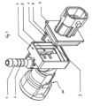
- the connector 100 has, as shown in FIG figure 1 can be seen, a housing 2, which consists of electrically insulating material, preferably a plastic, and a connector housing 7, wherein the housing 2 and the connector housing 7 together are connected.
- the connector 100 can be connected to a mating connector (not shown) so that a first fluid line can be connected to the connector 100 .
- the connector 100 also has a fluid connection element 5 to which a second fluid line can be connected.
- the fluid connection element 5 is preferably provided as a tube or tubular connection element, the longitudinal axis of which is arranged essentially perpendicular to a longitudinal axis of the plug connector 100 .
- a plug connector 100 is thus formed which can connect two fluid lines to one another, it being possible to achieve a right angle between the longitudinal axes of the respective fluid lines.
- the tubular fluid connection element 5 has projections 6 which are arranged around a circumference of the tubular fluid connection element 5 .
- a second fluid line which is provided in the form of a hose, can be fitted onto the fluid connection element 5 , with the projections 6 making it possible to hold the hose of the second fluid line on the fluid connection element 5 .
- the first fluid line can be provided in the form of a hose which is provided at its end with a mating connector 200 (not shown), the connector 100 according to the invention and the mating connector 200 being easily releasably connectable to one another.
- a medium to be heated both liquid and gaseous, flows between the first fluid line and the second fluid line.
- the connector 100 includes a heating element (not shown) that is supplied with electric power and generates heat to heat the medium.
- the heating element is supplied with electrical energy via contacts which are arranged in the plug housing 7 .
- the connector 100 according to the invention in the Figures 1 to 4 is shown connected to only one hose forming the first fluid line, the first fluid line can also comprise two hoses, each of which is provided with a mating connector.
- the connector 100 can be connected to any mating connector so that a T-junction can be formed.
- the connector housing 7 can be inserted into the housing 2 of the connector 100 and the connector 100 has a heating element 1 which is electrically connected to two contact elements 8, 9.
- the heating element 1 is provided, for example, as a PTC heating element, which is designed in the form of a rectangular thin plate, for example.
- the heating element 1 according to a preferred embodiment of the present invention is described in the form of a PTC heating element, it goes without saying that the heating element 1 can be provided in the form of a resistance wire, tubular heater or a heating cartridge, for example.
- a variety of heating elements can be provided in the connector 100 .
- the contact elements 8, 9 are therefore preferably designed as plates whose outer contour essentially corresponds to the outer contour of the heating element 1. How from the figure 2 seen, the contact elements 8, 9 are preferably rectangular. However, other configurations of the contact elements 8, 9 are also possible, provided that good heat transfer between the at least one heating element 1 and the contact elements 8, 9 can be achieved.
- the heating element 1 arranged between the contact elements 8 , 9 is arranged on the connector housing 7 .
- the heating element 1 is pushed into a housing part 3 of the housing 2 of the connector 100 .
- the housing part 3 is preferably provided in the form of a shaft 3, the dimensions of which correspond to the dimensions of the contact elements 8,9.
- a shaft wall separates the medium to be heated from the heating area in which the heating element 1 is located.
- the shaft 3 is sealed off by the flow channel 4 in which the medium to be heated flows. This ensures hermetic insulation between the heating area, in which the at least one heating element 1 is located, and the flow channel 4, in which the medium to be heated flows.
- the heating element 1 arranged between the contact elements 8, 9 is arranged in the shaft 3 in such a way that the heat transfer between the contact element 9 located closest to the flow channel 4 and the medium to be heated is as great as possible.
- the thickness of the shaft wall is selected in such a way that the heat transfer between the contact element 9 and the flow channel 4 is as large as possible.
- the figure 3 shows a section through the plug connector 100 according to the invention along a longitudinal axis of the plug connector 100.
- each of the contact elements 8, 9 has cranked plug-in tongues 8', 9'.
- the electrical energy can be introduced into the contact elements 8, 9 via the plug-in tongues 8', 9'.
- the arrangement of the plug-in tongues 8', 9' on the contact elements 8, 9 and their shape are designed in such a way that their ends lie next to one another when the plug-in connector 100 is in a plugged-in state.
- the heating element 1 is attached to the connector housing 7 with the insertion tongues 8', 9', the connector housing 7 being in the housing 2 of the connector 100 is inserted.
- the tongues 8', 9' of the contact elements 8, 9 can be connected to a power supply (not shown).
- the tongues 8 ', 9' extend in the assembled connector 100 in the connector housing 7 and thereby form the connector contacts of the connector 100.
- the plug in the Figures 1 to 4 is shown as a standardized plug with two knife-shaped plug-in tongues, other configurations and any number of plug-in tongues 8', 9' are of course also possible.
- the first contact element 8 is also designed as a spring element with spring tongues bent out. After the heating element 1 arranged between the contact elements 8, 9 has been inserted into the shaft 3, the spring tongues generate a spring force which presses the contact elements 8, 9 together against the heating element 1. This ensures good contact between the heating element 1 and the contact elements 8, 9. Thus, both the electrical flow and the heat transfer between the heating element 1 and the contact elements 8, 9 are increased.
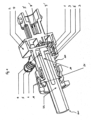
- FIG 4 shows another embodiment of the connector 100 according to the invention, which is shown here in an assembled state, in which it is connected to a first mating connector 200, which is arranged at the end of the first fluid line.
- the connector 100 preferably has latching elements 11 which can be latched with a corresponding radial latching recess 21 of the mating connector 200 .
- the mating connector 200 also has an elongated tubular channel 22 in which the medium to be heated flows.
- connector 100 according to the invention and the first mating connector 200 in the figure 4 are shown as snapped together, other holding devices are of course also possible, such as a clip device or a non-detachable pressing device.
- the connector 100 has a heating lance 10, which consists of a heat-conducting material, preferably copper, aluminum or stainless steel, and is elongated, so that the heating lance 10 can be inserted into a channel 22 of the first mating connector 200 .
- the heating lance 10 can also consist of a chemical-resistant material, preferably stainless steel. The heating lance 10 is thus resistant to the medium to be heated, which can be an aqueous urea solution, for example.
- the heating lance 10 has dimensions that are selected such that the end of the heating lance 10 is in a mated state in the first mating connector 200 .
- the heating lance 10 is preferably designed in the form of a tubular element, the diameter of which is adapted in such a way that the medium to be heated can flow in the channel 22 of the first mating connector 200 .
- the heat generated by the heating element 1 can be conducted into the first mating connector 200 due to the elongated pin-shaped design of the heating lance 10 .
- the heating lance 10 protrudes from the connector 100 in such a way that the heating lance 10 can be inserted into the first mating connector 200 in an assembled state.
- the heat generated by the heating element 1 can be conducted to the first mating connector 200 and thus potential ice build-up in the area of the first mating connector 200 can be eliminated.
- the thermally conductive heating lance 10 is thermally conductively connected to the heating element 1 so that the heat generated by the heating element 1 can be transferred to the heating lance 10 .
- the thickness of the shaft wall 3' is selected in such a way that an optimal heat transfer between the contact element 9 arranged closest to the flow channel 4 and the heating lance 10 is achieved.
- the cranked design of the tongues 8', 9' of the contact elements 8, 9 also serves to increase the heat exchange surface between the heating lance 10 and the contact elements 8, 9, so that the heat transfer to the heating lance 10 is as high as possible.
- the channel 22 of the first mating connector 200 has a thermally conductive layer on its inside, which preferably consists of a metal tube that is pressed into the channel 22 of the first mating connector 200 .
- a thermally conductive layer on its inside, which preferably consists of a metal tube that is pressed into the channel 22 of the first mating connector 200 .
- the fluid connection element 5 for connecting the second fluid line to the connector 100 in the Figures 1 to 4 shown as a tubular element onto which a second hose is directly fitted
- a quick connection between the second fluid line and the connector 100 can also be provided, which is similar to the quick connection between the first fluid line and the connector 100.
- the second fluid line comprises a second hose which is provided with a second mating connector, the connector 100 being able to be connected to the second mating connector.
Description
- Die vorliegende Erfindung betrifft einen Steckverbinder zum Verbinden einer ersten Fluidleitung mit einer zweiten Fluidleitung im Zusammenwirken mit mindestens einem Gegensteckverbinder, wobei ein Medium zwischen der ersten Fluidleitung und der zweiten Fluidleitung durch den Steckverbinder strömt.
- Solche Steckverbinder werden beispielsweise in Kraftfahrzeuge eingebaut, insbesondere in die Förderkette von wässrigen Harnstofflösungen, Kraftstoffen, Blowbygas, oder Reinigungsflüssigkeiten für die Scheiben- oder Scheinwerferreinigung. In einer derartigen Förderkette kann bei niedrigen Temperaturen die in der Förderkette enthaltene Flüssigkeit bzw. die im Gas enthaltene Feuchtigkeit einfrieren und es können Eisansätze vorkommen. Deshalb werden bei bekannten Anordnungen die diese Fluide fördernden Elemente der Förderkette, wie Pumpen oder Schläuche beheizt, um das Einfrieren derselben zu verhindern.
- Allerdings tritt ein Problem auf, wenn Elemente der Förderkette, z.B. beheizbare Schläuche durch einen Steckverbinder gemäß des Standes der Technik miteinander verbunden werden. Da die Flüssigkeit ausschließlich in den beheizbaren Schläuchen erwärmt wird und nicht in dem Steckverbinder, in welchem keinerlei Beheizung der darin strömenden Flüssigkeit vorgesehen ist, können bei niedrigen Temperaturen Eisansätze in dem Steckverbinder vorkommen.
- Die anhängige europäische Patentanmeldung
EP 1 557 601 A1 der Anmelderin beschreibt einen Heizclip für eine Fluidleitung, der ein in einem Gehäuse angeordnetes Heizelement umfasst und der an der Fluidleitung anclipbar ausgestaltet ist. Ein solcher Heizclip kann von Außen an die Fluidleitung angeclipst werden und kann an einer beliebigen Stelle entlang der Fluidleitung angeordnet werden. Allerdings ist ein solcher Heizclip nicht angepasst, ein zu erwärmendes Medium an der Schnittstelle zwischen zwei Fluidleitungen zu erwärmen. - Aus der
EP 0 284 669 A1 ist ebenfalls die Verbindung von beheizten Schläuchen beispielsweise mit unbeheizten Muffen bekannt. Weiterhin wird in diesem Dokument die Verbindung von beheizten Schläuchen über ein unbeheiztes Verbindungsstück beschrieben, wobei die Heizleiter der beheizten Schläuche teilweise zum Beheizen des Verbindungsstück verwendet werden. Dazu werden die an dem Verbindungsstück anliegenden Enden der Heizleiter verbunden und mit einem gemeinsamen Anschlusselement nach außen geführt. Verbindungselement, Heizleiter und Schlauchende sind mit einer Umhüllung aus Isoliermaterial umspritzt und bilden ein unlösbares Blockelement. - Die
EP 1 375 997 A1 zeigt einen Steckverbinder zum Verbinden einer ersten Fluidleitung mit einer zweiten Fluidleitung. Ein zu erwärmendes Medium strömt zwischen der ersten Fluidleitung und der zweiten Fluidleitung durch den aus Metall bestehenden Steckverbinder. Der Steckverbinder weist ein Heizelement zum Beheizen des zu erwärmenden Mediums auf, das in einer seitlichen Ausnehmung des rohrförmigen Steckverbinders angeordnet ist. Zur Montage und zum elektrischen Anschluss des Heizelements ist eine Haltevorrichtung aus Kunststoff vorgesehen. - Der Erfindung liegt daher die Aufgabe zugrunde, einen Steckverbinder der genannten Art dahingehend zu verbessern, dass ein Einfrieren eines durch den Steckverbinder strömenden Fluids auch im Steckverbinder verhindert werden kann.
- Gemäß der vorliegenden Erfindung wird diese Aufgabe durch einen Steckverbinder mit den Merkmalen des Patentanspruchs 1 gelöst.
- Vorteilhafte Weiterbildungen der vorliegenden Erfindung sind Gegenstand mehrerer Unteransprüche.
- Dadurch, dass der Steckverbinder mindestens ein Heizelement zum Beheizen des zu erwärmenden Mediums umfasst, wird die durch den Steckverbinder strömende Flüssigkeit erwärmt und mögliche Eisansätze können verhindert werden.
- Das Heizelement ist in einem Gehäuseteil des Steckverbinders eingeschlossen, der von dem zu erwärmenden Medium abgedichtet ist. Dadurch kann garantiert werden, dass das zu erwärmende Medium und der Heizbereich, in dem das Heizelement sich befindet, von einander fluidisch und elektrisch getrennt sind. Dies ermöglicht eine gute elektrische Isolation zwischen dem Heizbereich und dem durch den Steckverbinder strömenden zu erwärmenden Medium. Daneben wird durch die Trennung der Funktionsbereiche "Durchströmen" und "Heizen" eine sichere Abdichtung gegen durchtretendes Fluid erreicht.
- Gemäß einer bevorzugten Ausführungsform der vorliegenden Erfindung umfasst der Gehäuseteil einen im Gehäuse ausgestalteten Schacht, und das mindestens eine Heizelement ist in dem Schacht eingeschoben.
- Wenn der Steckverbinder einen Durchflusskanal umfasst, durch den das zu erwärmende Medium strömt, wobei das mindestens eine Heizelement von dem Durchflusskanal abgedichtet ist, kann gewährleistet werden, dass der Heizbereich, in dem sich das mindestens eine Heizelement befindet, und das zu erwärmende Medium voneinander hermetisch isoliert sind.
- Wenn die erste Fluidleitung einen ersten Schlauch umfasst, der mit einem ersten Gegensteckverbinder versehen ist, und der Steckverbinder mit dem ersten Gegensteckverbinder verbindbar ist, kann auf einfache Weise eine Schnellverbindung zwischen der ersten Fluidleitung und dem Steckverbinder hergestellt werden.
- Wenn die erste Fluidleitung zwei Schläuche umfasst, die jeweils mit einem ersten Gegensteckverbinder versehen sind, und der Steckverbinder mit jedem ersten Gegensteckverbinder verbindbar ist, wird die erste Fluidleitung durch zwei Schnellverbindungen mit dem Steckverbinder verbunden und somit eine T-Verzweigung gebildet.
- Wenn der Steckverbinder ein Fluidanschlusselement zum Verbinden der zweiten Fluidleitung mit dem Steckverbinder umfasst, wobei die zweite Fluidleitung einen zweiten Schlauch umfasst, und das Fluidanschlusselement rohrförmig ausgebildet ist, sodass der zweite Schlauch auf das Fluidanschlusselement aufsetzbar ist, kann auf einfache Weise die zweite Fluidleitung an den Steckverbinder angeschlossen werden. Vorzugsweise ist das Fluidanschlusselement mit Vorsprüngen zum Festhalten des aufgesetzten zweiten Schlauchs versehen, um einen sicheren Kontakt zwischen dem Steckverbinder und der zweiten Fluidleitung zu gewährleisten.
- Alternativ umfasst die zweite Fluidleitung einen zweiten Schlauch, der mit einem zweiten Gegensteckverbinder versehen ist, und der Steckverbinder ist mit dem zweiten Gegensteckverbinder verbindbar. Somit können die erste und zweite Fluidleitung durch Schnellverbindungen an den Steckverbinder angeschlossen werden.
- Wenn die erste Fluidleitung zwei Schläuche umfasst, die durch zwei Schnellverbindungen mit dem Steckverbinder verbunden sind und die zweite Fluidleitung auch durch eine Schnellverbindung an den Steckverbinder angeschlossen ist, wird eine T-Verzweigung gebildet, wobei drei Fluidleitungen mit maximal drei Schnellkupplungen mit dem Steckverbinder verbunden sind.
- Versieht man den Steckverbinder mit einer Heizlanze, die aus einem wärmeleitenden Material, vorzugsweise Kupfer, Aluminium oder Edelstahl, besteht und mit dem mindestens einen Heizelement wärmeleitend verbunden ist, kann die von dem mindestens einen Heizelement erzeugte Wärme auf die wärmeleitende Heizlanze übertragen werden, um ein Erwärmen des strömenden Mediums in einem von dem mindestens einen Heizelement entfernten Bereich des Steckverbinders zu ermöglichen. Die Heizlanze erhöht die Wärmeaustauschfläche zwischen dem zu erwärmenden Medium und dem Heizelement, sodass die von dem Heizelement erzeugte Wärme besser verteilt werden kann.
- Insbesondere, wenn die Heizlanze lang gestreckt ausgebildet ist und aus dem Steckverbinder herausragt, sodass die Heizlanze in einem zusammengesteckten Zustand in den Gegensteckverbinder einführbar ist, kann eine Vereisung des Gegensteckverbinders vermieden werden. Die von dem Heizelement erzeugte Wärme kann mittels der wärmeleitenden Heizlanze in den Bereich des Gegensteckverbinders übertragen und ein Eisansatz verhindert werden.
- Stellt man die Heizlanze aus einem chemikalienbeständigen Material, vorzugsweise Edelstahl, her, so ist die Heizlanze gegen z.B. wässrige Hamstofflösungen beständig, die durch den Steckverbinder strömen. Somit wird die Lebensdauer der Heizlanze erhöht.
- Besonders vorteilhaft ist es auch, wenn der Kanal des ersten Gegensteckverbinders eine wärmeleitfähige Schicht an seiner Innenseite aufweist, die vorzugsweise aus einem Metallrohr besteht, das in den Kanal des ersten Gegensteckverbinders eingepresst oder eingespritzt ist. Dadurch kann die von dem Heizelement erzeugte Wärme besser an den ersten Gegensteckverbinder abgegeben und eine noch effizientere Wärmeübertragung von dem Heizelement auf den ersten Gegensteckverbinder erreicht werden.
- Wenn der Steckverbinder zwei Kontaktelemente umfasst, die mit dem mindestens einen Heizelement elektrisch verbunden sind, wobei die zwei Kontaktelemente mit einer elektrischen Leistungsversorgung verbindbar sind, kann das mindestens eine Heizelement über die zwei Kontaktelemente elektrisch versorgt werden. Das mindestens eine Heizelement wandelt diese elektrische Energie in Wärme um, die an das Medium übertragen wird.
- Wenn das mindestens eine Heizelement zwischen den zwei Kontaktelementen angeordnet ist, kann ein guter Kontakt zwischen den Kontaktelementen und dem mindestens einen Heizelement garantiert und somit die elektrische Energie effizient an das Heizelement übertragen werden.
- Vorzugsweise umfasst der Steckverbinder ein Steckergehäuse, wobei die zwei Kontaktelemente je eine Steckzunge aufweisen, und die zwei Steckzungen in dem Steckergehäuse angeordnet sind. Somit bilden die Steckzungen der Kontaktelemente die Kontaktelemente eines elektrischen Steckers, und die elektrische Energie kann auf einfache Weise an die Kontaktelemente übertragen werden.
- Vorzugsweise umfasst das mindestens eine Heizelement ein Heizelement mit positivem Temperaturkoeffizienten, ein sogenanntes PTC-Element. Somit werden die an sich bekannten selbstregelnden Eigenschaften der PTC-Elemente ausgeschöpft, um die in dem Heizelement verbrauchte elektrische Leistung und die Temperatur des Heizelements zu regeln.
- Alternativ können aber auch alle anderen fachüblichen Heizvorrichtungen eingesetzt werden, so kann das mindestens eine Heizelement z.B. einen Widerstandsdraht, einen Rohrheizkörper oder eine Heizpatrone umfassen.
- Anhand der in den beiliegenden Zeichnungen dargestellten Ausgestaltungen wird die Erfindung im Folgenden näher erläutert. Ähnliche oder korrespondierende Einzelheiten des erfindungsgemäßen Steckverbinders sind in den Figuren mit denselben Bezugszeichen versehen. Es zeigen:
- Figur 1
- eine perspektivische Darstellung eines erfindungsgemäßen Steckverbinders;
- Figur 2
- eine teilweise explodierte perspektivische Darstellung eines Steckverbinders gemäß der vorliegenden Erfindung;
- Figur 3
- eine perspektivische Schnittdarstellung des erfindungsgemäßen Steckverbinders aus
Figur 1 ; - Figur 4
- eine perspektivische Schnittdarstellung des Steckverbinders gemäß einer zweiten Ausführungsform der vorliegenden Erfindung.
- Der erfindungsgemäße Steckverbinder 100 weist, wie aus der
Figur 1 ersichtlich, ein Gehäuse 2, das aus elektrisch isolierendem Material, vorzugsweise einem Kunststoff, besteht, und ein Steckergehäuse 7, wobei das Gehäuse 2 und das Steckergehäuse 7 miteinander verbunden sind. Der Steckverbinder 100 kann mit einem Gegensteck-verbinder (nicht dargestellt) verbunden werden, sodass eine erste Fluidleitung an den Steckverbinder 100 angeschlossen werden kann. - Der Steckverbinder 100 weist darüber hinaus ein Fluidanschlusselement 5 auf, an dem eine zweite Fluidleitung angeschlossen werden kann. Das Fluidanschlusselement 5 ist vorzugsweise als ein Rohr oder rohrförmiges Anschlusselement vorgesehen, dessen Längsachse im Wesentlichen senkrecht zu einer Längsachse des Steckverbinders 100 angeordnet ist. Somit wird ein Steckverbinder 100 gebildet, der zwei Fluidleitungen miteinander verbinden kann, wobei ein rechter Winkel zwischen den Längsachsen der jeweiligen Fluidleitungen erreicht werden kann.
- Das rohrförmige Fluidanschlusselement 5 weist Vorsprünge 6 auf, die um einen Umfang des rohrförmigen Fluidanschlusselements 5 angeordnet sind. Eine zweite Fluidleitung, die in Form eines Schlauchs vorgesehen ist, kann auf das Fluidanschlusselement 5 aufgesetzt werden, wobei die Vorsprünge 6 es ermöglichen, den Schlauch der zweiten Fluidleitung an dem Fluidanschlusselement 5 festzuhalten.
- Die erste Fluidleitung kann in Form eines Schlauchs vorgesehen werden, der an seinem Ende mit einem Gegensteckverbinder 200 (nicht dargestellt) versehen ist, wobei der erfindungsgemäße Steckverbinder 100 und der Gegensteckverbinder 200 einfach lösbar miteinander verbindbar sind. In einem Betriebszustand strömt ein zu erwärmendes Medium, sowohl flüssiges als auch gasförmiges, zwischen der ersten Fluidleitung und der zweiten Fluidleitung.
- Der Steckverbinder 100 beinhaltet ein Heizelement (nicht dargestellt), das mit elektrischer Energie versorgt wird und Wärme erzeugt, um das Medium zu erwärmen. Das Heizelement wird über Kontakte, die in dem Steckergehäuse 7 angeordnet sind, mit elektrischer Energie versorgt.
- Obwohl der erfindungsgemäße Steckverbinder 100 in den
Figuren 1 bis 4 nur mit einem die erste Fluidleitung bildenden Schlauch verbunden dargestellt wird, kann die erste Fluidleitung auch zwei Schläuche umfassen, die jeweils mit einem Gegensteckverbinder versehen sind. Der Steckverbinder 100 ist mit jedem Gegensteckverbinder verbindbar, so dass eine T-Verzweigung gebildet werden kann. - Wie aus der
Figur 2 ersichtlich, die eine teilweise explodierte perspektivische Darstellung des erfindungsgemäßen Steckverbinders 100 zeigt, ist das Steckergehäuse 7 in das Gehäuse 2 des Steckverbinders 100 einschiebbar und der Steckverbinder 100 weist ein Heizelement 1, das mit zwei Kontaktelementen 8, 9 elektrisch verbunden ist, auf. Das Heizelement 1 ist beispielsweise als PTC-Heizelement vorgesehen, das in Form einer z.B. rechteckigen dünnen Platte ausgestaltet ist. Obwohl das Heizelement 1 gemäß einer bevorzugten Ausführungsform der vorliegenden Erfindung in Form eines PTC-Heizelements beschrieben wird, kann selbstverständlich das Heizelement 1 beispielsweise in Form eines Widerstandsdrahts, Rohrheizkörpers oder einer Heizpatrone vorgesehen werden. Darüber hinaus können eine Vielzahl von Heizelementen in dem Steckverbinder 100 vorgesehen werden. - Bei der in
Figur 2 dargestellten Ausführungsform des erfindungsgemäßen Steckverbinders 100 fließt im Betrieb eine elektrische Energie über die beiden Kontaktelemente 8, 9 durch das PTC-Heizelement 1 hindurch. Die erzeugte Wärmeenergie kann über die beiden Plattenflächen des PTC-Heizelements 1 besonders gut abgegeben werden. Die Kontaktelemente 8, 9 sind daher vorzugsweise als Platten ausgestaltet, deren Außenkontur im Wesentlichen der Außenkontur des Heizelements 1 entspricht. Wie aus derFigur 2 ersichtlich, sind die Kontaktelemente 8, 9 vorzugsweise rechteckig. Andere Ausgestaltungen der Kontaktelemente 8, 9 sind aber auch möglich, vorausgesetzt, dass eine gute Wärmeübertragung zwischen dem mindestens einen Heizelement 1 und den Kontaktelementen 8, 9 erreicht werden kann. - Das zwischen den Kontaktelementen 8, 9 angeordnete Heizelement 1 ist an dem Steckergehäuse 7 angeordnet. Das Heizelement 1 wird in einen Gehäuseteil 3 des Gehäuses 2 des Steckverbinders 100 eingeschoben. Das Gehäuseteil 3 ist vorzugsweise in Form eines Schachts 3 vorgesehen, dessen Abmessungen den Abmessungen der Kontaktelemente 8, 9 entsprechen. Eine Schachtwand trennt das zu erwärmende Medium vom Heizbereich, in dem sich das Heizelement 1 befindet. Der Schacht 3 ist von dem Durchflusskanal 4, in dem das zu erwärmende Medium fließt, abgedichtet. Somit wird eine hermetische Isolation zwischen dem Heizbereich, in dem sich das mindestens eine Heizelement 1 befindet, und dem Durchflusskanal 4, in dem das zu erwärmende Medium strömt, gewährleistet.
Das zwischen den Kontaktelementen 8, 9 angeordnete Heizelement 1 ist in dem Schacht 3 so angeordnet, dass die Wärmeübertragung zwischen dem sich vom Durchflusskanal 4 am nächsten befindenden Kontaktelement 9 und dem zu erwärmenden Medium so groß wie möglich ist. Die Dicke der Schachtwand wird so ausgewählt, dass die Wärmeübertragung zwischen dem Kontaktelement 9 und dem Durchflusskanal 4 so groß wie möglich ist. - Die
Figur 3 zeigt einen Schnitt durch den erfindungsgemäßen Steckverbinder 100 entlang einer Längsachse des Steckverbinders 100. Wie aus dieser Figur ersichtlich, sind an den Kontaktelementen 8, 9 jeweils gekröpfte Steckzungen 8', 9' ausgestaltet. Über die Steckzungen 8', 9' können im Betrieb des erfindungsgemäßen Steckverbinders 100 die elektrische Energie in die Kontaktelemente 8, 9 eingeleitet werden. Die Anordnung der Steckzungen 8', 9' an den Kontaktelementen 8, 9 und ihre Form sind so ausgestaltet, dass ihre Enden in einem zusammengesteckten Zustand des Steckverbinders 100 nebeneinander liegen. - Das Heizelement 1 ist mit den Steckzungen 8', 9' an dem Steckergehäuse 7 angebracht, wobei das Steckergehäuse 7 im Gehäuse 2 des Steckverbinders 100 eingeschoben ist.
- Die Steckzungen 8', 9' der Kontaktelemente 8, 9 sind mit einer Energieversorgung (nicht dargestellt) verbindbar. Die Steckzungen 8', 9' erstrecken sich bei dem montierten Steckverbinder 100 in das Steckergehäuse 7 und bilden dadurch die Steckerkontakte des Steckverbinders 100. Obwohl der Stecker in den
Figuren 1 bis 4 als ein standardisierter Stecker mit zwei messerförmigen Steckzungen dargestellt wird, sind selbstverständlich andere Ausgestaltungen und eine beliebige Anzahl der Steckzungen 8', 9' ebenfalls möglich. - Wie aus der
Figur 3 ersichtlich, ist weiterhin das erste Kontaktelement 8 als Federelement mit herausgebogenen Federzungen ausgebildet. Nachdem das zwischen den Kontaktelementen 8, 9 angeordnete Heizelement 1 in den Schacht 3 eingeführt wurde, erzeugen die Federzungen eine Federkraft, die die Kontaktelemente 8, 9 gegen das Heizelement 1 zusammendrücken. Dadurch wird ein guter Kontakt zwischen dem Heizelement 1 und den Kontaktelementen 8, 9 gewährleistet. Somit wird sowohl der elektrische Fluss als auch die Wärmeübertragung zwischen dem Heizelement 1 und den Kontaktelementen 8, 9 erhöht. -
Figur 4 zeigt eine weitere Ausführungsform des erfindungsgemäßen Steckverbinders 100, der hier in einem zusammengesteckten Zustand dargestellt ist, in dem er mit einem ersten Gegensteckverbinder 200 verbunden ist, der am Ende der ersten Fluidleitung angeordnet ist. Der Steckverbinder 100 weist vorzugsweise Rastelemente 11 auf, die mit einer entsprechenden radialen Rastausnehmung 21 des Gegensteckverbinders 200 verrastbar sind. Der Gegensteckverbinder 200 weist darüber hinaus einen lang gestreckten rohrförmigen Kanal 22 auf, in dem das zu erwärmende Medium strömt. - Obwohl der erfindungsgemäße Steckverbinder 100 und der erste Gegensteckverbinder 200 in der
Figur 4 als miteinander verrastbar dargestellt sind, sind auch selbstverständlich andere Haltevorrichtungen möglich, wie beispielsweise eine Clipvorrichtung oder eine unlösbare Verpressvorrichtung. - Gemäß einer in
Figur 4 dargestellten bevorzugten Ausführungsform der vorliegenden Erfindung weist der Steckverbinder 100 eine Heizlanze 10 auf, die aus einem wärmeleitenden Material, vorzugsweise Kupfer, Aluminium oder Edelstahl, besteht, und lang gestreckt ausgestaltet ist, sodass die Heizlanze 10 in einen Kanal 22 des ersten Gegensteckverbinders 200 einführbar ist. Die Heizlanze 10 kann darüber hinaus aus einem chemikalienbeständigen Material, vorzugsweise Edelstahl, bestehen. Somit ist die Heizlanze 10 gegenüber dem zu erwärmenden Medium, das beispielsweise eine wässrige Hamstofflösung sein kann, beständig. - Die Heizlanze 10 weist Abmessungen auf, die so ausgewählt sind, dass das Ende der Heizlanze 10 in einem zusammengesteckten Zustand sich in dem ersten Gegensteckverbinder 200 befindet. Darüber hinaus ist die Heizlanze 10 vorzugsweise in Form eines rohrförmigen Elements ausgebildet, dessen Durchmesser so angepasst ist, dass das zu erwärmende Medium in dem Kanal 22 des ersten Gegensteckverbinders 200 fließen kann.
- Durch die längliche stiftförmige Ausgestaltung der Heizlanze 10 kann die von dem Heizelement 1 erzeugte Wärme in den ersten Gegensteckverbinder 200 geleitet werden. Die Heizlanze 10 ragt aus dem Steckverbinder 100 so heraus, dass die Heizlanze 10 in einem zusammengesteckten Zustand in den ersten Gegensteckverbinder 200 einführbar ist. Dadurch können die von dem Heizelement 1 erzeugte Wärme an den ersten Gegensteckverbinder 200 geleitet und somit potentielle Eisansätze im Bereich des ersten Gegensteckverbinders 200 beseitigt werden.
- Die wärmeleitende Heizlanze 10 ist mit dem Heizelement 1 wärmeleitend verbunden, sodass die von dem Heizelement 1 erzeugte Wärme an die Heizlanze 10 übertragen werden kann. Die Dicke der Schachtwand 3' ist so ausgewählt, dass eine optimale Wärmeübertagung zwischen dem vom Durchflusskanal 4 am nächsten angeordneten Kontaktelement 9 und der Heizlanze 10 erreicht wird. Die gekröpfte Ausgestaltung der Steckzungen 8', 9' der Kontaktelemente 8, 9 dient auch dazu, die Wärmeaustauschfläche zwischen der Heizlanze 10 und den Kontaktelementen 8, 9 zu erhöhen, damit die Wärmeübertragung zur Heizlanze 10 so hoch wie möglich ist.
- Der Kanal 22 des ersten Gegensteckverbinders 200 weist eine wärmeleitfähige Schicht an seiner Innenseite auf, die vorzugsweise aus einem Metallrohr besteht, das in den Kanal 22 des ersten Gegensteckverbinders 200 eingepresst ist. Dadurch kann die von dem Heizelement 1 erzeugte Wärme besser an den ersten Gegensteckverbinder 200 abgegeben werden. Somit wird die Wärmeübertragung auf den ersten Gegensteckverbinder 200 noch effizienter.
- Obwohl das Fluidanschlusselement 5 zum Verbinden der zweiten Fluidleitung mit dem Steckverbinder 100 in den
Figuren 1 bis 4 als ein rohrförmiges Element, auf das ein zweiter Schlauch direkt aufgesetzt wird, dargestellt wurde, kann aber auch eine Schnellverbindung zwischen der zweiten Fluidleitung und dem Steckverbinder 100 vorgesehen werden, die ähnlich zur Schnellverbindung zwischen der ersten Fluidleitung und dem Steckverbinder 100 ist. Die zweite Fluidleitung umfasst dabei einen zweiten Schlauch, der mit einem zweiten Gegensteckverbinder versehen ist, wobei der Steckverbinder 100 mit dem zweiten Gegensteckverbinder verbindbar ist.
Claims (23)
- Steckverbinder zum Verbinden einer ersten Fluidleitung mit einer zweiten Fluidleitung im Zusammenwirken mit mindestens einem Gegensteckverbinder (200), wobei ein zu erwärmendes Medium zwischen der ersten Fluidleitung und der zweiten Fluidleitung durch den Steckverbinder (100) strömt, und der Steckverbinder (100) mindestens ein Heizelement (1) zum Beheizen des zu erwärmenden Mediums umfasst, weiterhin umfassend ein Gehäuse (2) aus elektrisch isolierendem Material, vorzugsweise einem Kunststoff, wobei das mindestens eine Heizelement (1) in einem Gehäuseteil (3) des Steckverbinders (100) eingeschlossen ist, der gegenüber dem zu erwärmenden Medium abgedichtet ist.
- Steckverbinder nach Anspruch 1, wobei der Gehäuseteil (3) einen im Gehäuse (2) ausgestalteten Schacht (3) umfasst, und das mindestens eine Heizelement (1) in dem Schacht (3) eingeschoben ist.
- Steckverbinder nach einem der Ansprüche 1 bis 2, weiterhin umfassend einen Durchflusskanal (4), durch den das zu erwärmende Medium strömt, wobei das mindestens eine Heizelement (1) gegenüber dem Durchflusskanal (4) abgedichtet ist.
- Steckverbinder nach einem der Ansprüche 1 bis 3, weiterhin umfassend ein Fluidanschlusselement (5) zum Verbinden der zweiten Fluidleitung mit dem Steckverbinder (100).
- Steckverbinder nach Anspruch 4, wobei die zweite Fluidleitung einen zweiten Schlauch umfasst, und das Fluidanschlusselement (5) rohrförmig ausgebildet ist, so dass der zweite Schlauch auf das Fluidanschlusselement (5) aufsetzbar ist.
- Steckverbinder nach Anspruch 5, wobei das Fluidanschlusselement (5) mit Vorsprüngen (6) zum Festhalten des aufgesetzten zweiten Schlauchs versehen ist.
- Steckverbinder nach einem der Ansprüche 1 bis 6, wobei der Steckverbinder (100) so ausgebildet ist, dass die erste Fluidleitung und die zweite Fluidleitung mit einem Winkel zwischen 30° und 180°, vorzugsweise 90°, zu einander angeordnet sind.
- Steckverbinder nach einem der Ansprüche 1 bis 7, weiterhin umfassend zwei Kontaktelemente (8, 9), die mit dem mindestens einen Heizelement (1) elektrisch verbunden sind, wobei die zwei Kontaktelemente (8, 9) mit einer elektrischen Leistungsversorgung verbindbar sind.
- Steckverbinder nach Anspruch 8, wobei das mindestens eine Heizelement (1) zwischen den zwei Kontaktelementen (8, 9) angeordnet ist.
- Steckverbinder nach einem der Ansprüche 8 oder 9 weiterhin umfassend ein Steckergehäuse (7), wobei die zwei Kontaktelemente (8, 9) je eine Steckzunge (8', 9') aufweisen, und die zwei Steckzungen (8', 9') in dem Steckergehäuse (7) angeordnet sind.
- Steckverbinder nach einem der Ansprüche 1 bis 10, wobei das mindestens eine Heizelement (1) ein PTC-Element umfasst.
- Steckverbinder nach einem der Ansprüche 1 bis 10, wobei das mindestens eine Heizelement (1) einen Widerstandsdraht umfasst.
- Steckverbinder nach einem der Ansprüche 1 bis 10, wobei das mindestens eine Heizelement (1) einen Rohrheizkörper umfasst.
- Steckverbinder nach einem der Ansprüche 1 bis 10, wobei das mindestens eine Heizelement (1) eine Heizpatrone umfasst.
- Steckverbinder nach einem der Ansprüche 1 bis 14, weiterhin umfassend eine Heizlanze (10), die aus einem wärmeleitenden Material, vorzugsweise Kupfer, Aluminium oder Edelstahl, besteht und mit den mindestens einen Heizelement (1) wärmeleitend verbunden ist.
- Steckverbinder nach Anspruch 15, wobei die Heizlanze (10) lang gestreckt ausgebildet ist und aus dem Steckverbinder (100) herausragt, so dass die Heizlanze (10) in einem zusammengesteckten Zustand in den mindestens einen Gegensteckverbinder (200) einführbar ist.
- Steckverbinder nach einem der Ansprüche 15 oder 16, wobei die Heizlanze (10) aus einem chemikalienbeständigen Material besteht, vorzugsweise Edelstahl.
- Steckverbinder nach einem der Ansprüche 1 bis 17, wobei der Steckverbinder (100) angepasst ist, ein flüssiges oder gasförmiges Medium zu erwärmen.
- Steckverbinderanordnung umfassend einen Steckverbinder (100) nach einem der Ansprüche 1 bis 18 und mindestens einem ersten Gegensteckverbinder (200), wobei die erste Fluidleitung einen ersten Schlauch umfasst, der mit dem mindestens einen ersten Gegensteckverbinder (200) versehen ist, und der Steckverbinder (100) mit dem mindestens einen ersten Gegensteckverbinder (200) verbindbar ist.
- Steckverbinderanordnung nach Anspruch 19, wobei die erste Fluidleitung zwei Schläuche umfasst, die jeweils mit einem ersten Gegensteckverbinder versehen sind, und der Steckverbinder (100) mit jedem ersten Gegensteckverbinder verbindbar ist.
- Steckverbinderanordnung nach einem der Ansprüche 19 oder 20, wobei die zweite Fluidleitung einen zweiten Schlauch umfasst, der mit einem zweiten Gegensteckverbinder verstehen ist, und der Steckverbinder (100) mit dem zweiten Gegensteckverbinder verbindbar ist.
- Steckverbinderanordnung nach einem der Ansprüche 19 bis 21, wobei der erste Gegensteckverbinder (200) einen Kanal (22) aufweist, dessen Innenseite mit einer wärmeleitfähigen Schicht verstehen ist.
- Steckverbinderanordnung nach Anspruch 22, wobei die wärmeleitfähige Schicht ein Metallrohr umfasst, das in den Kanal (22) eingepresst oder eingespritzt ist.
Applications Claiming Priority (1)
| Application Number | Priority Date | Filing Date | Title |
|---|---|---|---|
| DE102005050867A DE102005050867A1 (de) | 2005-10-24 | 2005-10-24 | Beheizbarer Steckverbinder |
Publications (4)
| Publication Number | Publication Date |
|---|---|
| EP1777452A2 EP1777452A2 (de) | 2007-04-25 |
| EP1777452A3 EP1777452A3 (de) | 2009-09-23 |
| EP1777452B1 EP1777452B1 (de) | 2010-08-25 |
| EP1777452B2 true EP1777452B2 (de) | 2023-05-03 |
Family
ID=37691818
Family Applications (1)
| Application Number | Title | Priority Date | Filing Date |
|---|---|---|---|
| EP06022243.7A Active EP1777452B2 (de) | 2005-10-24 | 2006-10-24 | Beheizbarer Steckverbinder |
Country Status (3)
| Country | Link |
|---|---|
| EP (1) | EP1777452B2 (de) |
| AT (1) | ATE479048T1 (de) |
| DE (2) | DE102005050867A1 (de) |
Families Citing this family (20)
| Publication number | Priority date | Publication date | Assignee | Title |
|---|---|---|---|---|
| EP2137449B2 (de) † | 2007-04-26 | 2018-10-17 | Voss Automotive GmbH | Leitungsverbinder für medienleitungen |
| DE202007015036U1 (de) | 2007-10-26 | 2009-03-12 | Voss Automotive Gmbh | Leitungsverbinder sowie Leitungssatz für fluidische Medien |
| PL2222995T3 (pl) * | 2007-12-21 | 2015-04-30 | Voss Automotive Gmbh | Element połączeniowy przewodów dla przewodów dla mediów oraz zespolony przewód dla mediów z co najmniej jednym takim elementem połączeniowym przewodów |
| DE202007018089U1 (de) | 2007-12-21 | 2009-05-07 | Voss Automotive Gmbh | Beheizbare Medienleitung |
| US9651185B2 (en) | 2008-03-19 | 2017-05-16 | Voss Automotive Gmbh | Line connector for media lines |
| CN102597592B (zh) * | 2009-06-24 | 2016-04-13 | 福士汽车配套部件责任有限公司 | 能够电加热的介质导管以及导管连接器 |
| DE202009012431U1 (de) * | 2009-09-15 | 2011-02-10 | A. Raymond Et Cie S.C.S. | Verbindungseinrichtung für eine Scheibenwischeranlage |
| DE102009044404A1 (de) | 2009-11-03 | 2011-05-05 | Contitech Techno-Chemie Gmbh | System zum Verbinden von Schlauchleitungen |
| DE102010033757A1 (de) * | 2010-08-09 | 2012-02-09 | Dbk David + Baader Gmbh | Fluidleiteinrichtung |
| CN103998845B (zh) * | 2011-10-14 | 2017-11-03 | 福士汽车配套部件责任有限公司 | 用于可加热的介质管道的可至少部分加热的管道连接器和具有该管道连接器的组装介质管道 |
| DE102011088659A1 (de) | 2011-12-15 | 2013-06-20 | Robert Bosch Gmbh | Vorrichtung zum Befestigen eines Dosierventils |
| FR2984256B1 (fr) * | 2011-12-19 | 2016-09-02 | Valeo Systemes Dessuyage | Composant plastique et thermoconducteur d'un systeme d'approvisionnement et/ou de distribution en liquide lave glace de vehicule automobile |
| FR3003219B1 (fr) * | 2013-03-14 | 2016-11-18 | Valeo Systemes Dessuyage | Dispositif de distribution de liquide lave-glace de balais d'essuie-glace de vehicule automobile |
| DE102014004134A1 (de) | 2014-03-24 | 2015-09-24 | A. Kayser Automotive Systems Gmbh | Beheizbare Leitung |
| DE102014107863A1 (de) * | 2014-06-04 | 2015-12-17 | Emitec Gesellschaft Für Emissionstechnologie Mbh | Verfahren zur Funktionsprüfung mindestens eines PTC-Heizelementes |
| DE102015112519A1 (de) * | 2015-07-30 | 2017-02-02 | Norma Germany Gmbh | Windschutzhülle und eine Steckverbindungsvorrichtung mit einer solchen |
| DE102015112448A1 (de) * | 2015-07-30 | 2017-02-02 | Dr. Ing. H.C. F. Porsche Aktiengesellschaft | Taste für ein Ladetastenmodul, entsprechendes Ladetastenmodul, Verfahren, Computerprogramm und Speichermedium |
| EP3211190B1 (de) * | 2016-02-23 | 2019-04-17 | TI Automotive (Fuldabrück) GmbH | Verbinderanordnung mit zumindest einem verbinder und zumindest einer medienleitung |
| EP3284923B1 (de) * | 2016-08-18 | 2019-03-20 | J.S.T. Mfg. Co., Ltd. | Fluidzirkulationssystem für automobil und stecker |
| CN114321533A (zh) * | 2021-12-24 | 2022-04-12 | 苏州恩都法汽车系统有限公司 | 一种多功能快插接头结构 |
Citations (22)
| Publication number | Priority date | Publication date | Assignee | Title |
|---|---|---|---|---|
| EP0068688A2 (de) † | 1981-06-15 | 1983-01-05 | RAYCHEM CORPORATION (a California corporation) | In der Brennstoffleitung eingebauter Brennstoffvorwärmer |
| US4447707A (en) † | 1981-12-22 | 1984-05-08 | Nordson Corporation | Electrically heated multi-section hose having electrically heated hose joints |
| DE3324268A1 (de) † | 1983-07-06 | 1985-01-17 | Vdo Adolf Schindling Ag, 6000 Frankfurt | Spritzduesenvorrichtung |
| EP0502322A1 (de) † | 1991-03-05 | 1992-09-09 | Mercedes-Benz Ag | Scheibenwascheinrichtung mit einem Halteteil zu deren Befestigung |
| DE4135082C1 (en) † | 1991-10-24 | 1992-12-10 | Klaus 6900 Heidelberg De Winkler | Heatable hose for flowing medium connectable to installation or machine - has electrical element surrounding inner conveying core and sleeve for connector to prevent heat loss |
| EP0616166A1 (de) † | 1993-03-17 | 1994-09-21 | Applied Materials, Inc. | Heizbare Fluidleitung |
| EP0353643B1 (de) † | 1988-08-05 | 1995-05-03 | Audi Ag | Beheizbare Scheibenwaschanlagendüse |
| DE19846282A1 (de) † | 1998-10-08 | 2000-04-13 | Mann & Hummel Filter | Beheizbare Wand |
| DE19855288A1 (de) † | 1998-11-24 | 2000-05-25 | Sterken Hans Peter | Verfahren zum gegenseitigen Lokalisieren von nach astrologischen Apekten miteinander harmonisierenden Personen mittels Infrarot-Übertragungstechnik |
| DE19901029A1 (de) † | 1999-01-14 | 2000-07-20 | Continental Teves Ag & Co Ohg | Beheizbare Rohrleitung für eine hydraulische Bremsvorrichtung |
| DE19902432A1 (de) † | 1999-01-22 | 2000-08-10 | Mannesmann Vdo Ag | Beheizte Waschdüse mit Anschlußstück |
| EP1070642A2 (de) † | 1999-07-22 | 2001-01-24 | REHAU AG + Co | Heizvorrichtung für Scheibenwaschanlage |
| DE10023649A1 (de) † | 2000-05-13 | 2001-12-06 | Mahle Filtersysteme Gmbh | Mit einer Heizeinrichtung versehenes Kraftstoffilter für Kraftfahrzeuge |
| US20020040895A1 (en) † | 2000-06-08 | 2002-04-11 | Lopez Miguel Mota | De-icing system |
| DE20107321U1 (de) † | 2001-04-27 | 2002-09-05 | Roehrig Werner | Leitungsanordnung |
| EP1375997A1 (de) † | 2002-06-27 | 2004-01-02 | David & Baader DBK Spezialfabrik elektrischer Apparate und Heizwiderstände GmbH | Heizvorrichtung für eine Fluidleitung und Verfahren zur Herstellung |
| DE10212413A1 (de) † | 2002-03-21 | 2004-01-15 | Valeo Auto-Electric Wischer Und Motoren Gmbh | Waschwasserschlauch und Steckverbinder |
| US6688650B2 (en) † | 2001-12-04 | 2004-02-10 | Sun Microsystems, Inc. | Dry disconnect fluidic coupling |
| EP1513227A1 (de) † | 2003-09-03 | 2005-03-09 | MAN Nutzfahrzeuge Aktiengesellschaft | Vorrichtung zur Führung eines fliessfähigen Mediums |
| EP1610049A2 (de) † | 2004-05-03 | 2005-12-28 | ContiTech Techno-Chemie GmbH | Schlauchverbindungssystem für einen beheizbaren Schlauch |
| WO2005124219A1 (en) † | 2004-06-15 | 2005-12-29 | Volvo Lastvagnar Ab | Electrically heatable coupling and an encased fluid hose with an electrically heatable coupling |
| WO2007032034A1 (en) † | 2005-09-16 | 2007-03-22 | Dayco Fluid Technologies S.P.A. | Pipe fitting for a heatable piping of a scr system |
Family Cites Families (4)
| Publication number | Priority date | Publication date | Assignee | Title |
|---|---|---|---|---|
| DE8704903U1 (de) * | 1987-04-02 | 1987-05-27 | Rehau Ag + Co, 8673 Rehau, De | |
| US5791377A (en) * | 1996-07-08 | 1998-08-11 | Yazaki Corporation | Electrically heated conduit |
| DE10055423A1 (de) * | 2000-11-09 | 2002-05-23 | Bosch Gmbh Robert | Anordnung zum Erwärmen von Flüssigkeit in einem Leitungssystem |
| ATE330165T1 (de) * | 2004-01-23 | 2006-07-15 | Dbk David & Baader Gmbh | Heizclip für eine fluidleitung |
-
2005
- 2005-10-24 DE DE102005050867A patent/DE102005050867A1/de not_active Ceased
-
2006
- 2006-10-24 AT AT06022243T patent/ATE479048T1/de active
- 2006-10-24 EP EP06022243.7A patent/EP1777452B2/de active Active
- 2006-10-24 DE DE502006007721T patent/DE502006007721D1/de active Active
Patent Citations (22)
| Publication number | Priority date | Publication date | Assignee | Title |
|---|---|---|---|---|
| EP0068688A2 (de) † | 1981-06-15 | 1983-01-05 | RAYCHEM CORPORATION (a California corporation) | In der Brennstoffleitung eingebauter Brennstoffvorwärmer |
| US4447707A (en) † | 1981-12-22 | 1984-05-08 | Nordson Corporation | Electrically heated multi-section hose having electrically heated hose joints |
| DE3324268A1 (de) † | 1983-07-06 | 1985-01-17 | Vdo Adolf Schindling Ag, 6000 Frankfurt | Spritzduesenvorrichtung |
| EP0353643B1 (de) † | 1988-08-05 | 1995-05-03 | Audi Ag | Beheizbare Scheibenwaschanlagendüse |
| EP0502322A1 (de) † | 1991-03-05 | 1992-09-09 | Mercedes-Benz Ag | Scheibenwascheinrichtung mit einem Halteteil zu deren Befestigung |
| DE4135082C1 (en) † | 1991-10-24 | 1992-12-10 | Klaus 6900 Heidelberg De Winkler | Heatable hose for flowing medium connectable to installation or machine - has electrical element surrounding inner conveying core and sleeve for connector to prevent heat loss |
| EP0616166A1 (de) † | 1993-03-17 | 1994-09-21 | Applied Materials, Inc. | Heizbare Fluidleitung |
| DE19846282A1 (de) † | 1998-10-08 | 2000-04-13 | Mann & Hummel Filter | Beheizbare Wand |
| DE19855288A1 (de) † | 1998-11-24 | 2000-05-25 | Sterken Hans Peter | Verfahren zum gegenseitigen Lokalisieren von nach astrologischen Apekten miteinander harmonisierenden Personen mittels Infrarot-Übertragungstechnik |
| DE19901029A1 (de) † | 1999-01-14 | 2000-07-20 | Continental Teves Ag & Co Ohg | Beheizbare Rohrleitung für eine hydraulische Bremsvorrichtung |
| DE19902432A1 (de) † | 1999-01-22 | 2000-08-10 | Mannesmann Vdo Ag | Beheizte Waschdüse mit Anschlußstück |
| EP1070642A2 (de) † | 1999-07-22 | 2001-01-24 | REHAU AG + Co | Heizvorrichtung für Scheibenwaschanlage |
| DE10023649A1 (de) † | 2000-05-13 | 2001-12-06 | Mahle Filtersysteme Gmbh | Mit einer Heizeinrichtung versehenes Kraftstoffilter für Kraftfahrzeuge |
| US20020040895A1 (en) † | 2000-06-08 | 2002-04-11 | Lopez Miguel Mota | De-icing system |
| DE20107321U1 (de) † | 2001-04-27 | 2002-09-05 | Roehrig Werner | Leitungsanordnung |
| US6688650B2 (en) † | 2001-12-04 | 2004-02-10 | Sun Microsystems, Inc. | Dry disconnect fluidic coupling |
| DE10212413A1 (de) † | 2002-03-21 | 2004-01-15 | Valeo Auto-Electric Wischer Und Motoren Gmbh | Waschwasserschlauch und Steckverbinder |
| EP1375997A1 (de) † | 2002-06-27 | 2004-01-02 | David & Baader DBK Spezialfabrik elektrischer Apparate und Heizwiderstände GmbH | Heizvorrichtung für eine Fluidleitung und Verfahren zur Herstellung |
| EP1513227A1 (de) † | 2003-09-03 | 2005-03-09 | MAN Nutzfahrzeuge Aktiengesellschaft | Vorrichtung zur Führung eines fliessfähigen Mediums |
| EP1610049A2 (de) † | 2004-05-03 | 2005-12-28 | ContiTech Techno-Chemie GmbH | Schlauchverbindungssystem für einen beheizbaren Schlauch |
| WO2005124219A1 (en) † | 2004-06-15 | 2005-12-29 | Volvo Lastvagnar Ab | Electrically heatable coupling and an encased fluid hose with an electrically heatable coupling |
| WO2007032034A1 (en) † | 2005-09-16 | 2007-03-22 | Dayco Fluid Technologies S.P.A. | Pipe fitting for a heatable piping of a scr system |
Also Published As
| Publication number | Publication date |
|---|---|
| DE502006007721D1 (de) | 2010-10-07 |
| EP1777452A3 (de) | 2009-09-23 |
| EP1777452A2 (de) | 2007-04-25 |
| EP1777452B1 (de) | 2010-08-25 |
| DE102005050867A1 (de) | 2007-04-26 |
| ATE479048T1 (de) | 2010-09-15 |
Similar Documents
| Publication | Publication Date | Title |
|---|---|---|
| EP1777452B2 (de) | Beheizbarer Steckverbinder | |
| EP1375997B1 (de) | Heizvorrichtung für eine Fluidleitung und Verfahren zur Herstellung | |
| EP2428746B1 (de) | Wärmeübertrager | |
| DE102007005771B4 (de) | Filtereinrichtung, insbesondere Flüssigkeitsfilter, mit einer Heizung | |
| EP2592982B1 (de) | Dynamischer durchlauferhitzer | |
| EP2513987B1 (de) | Thermoelektrische einheit | |
| EP2428747B1 (de) | Wärmeübertrager | |
| EP1375999B1 (de) | Heizvorrichtung zur Kurbelgehäuseentlüftung für Verbrennungskraftmaschinen und Herstellverfahren | |
| EP3273177A1 (de) | Elektrische heizvorrichtung | |
| WO2013053478A1 (de) | Zumindest teilweise beheizbarer leitungsverbinder für eine beheizbare medienleitung sowie konfektionierte medienleitung mit einem solchen leitungsverbinder | |
| DE102019204401A1 (de) | PTC-Heizelement und elektrische Heizvorrichtung umfassend ein solches | |
| EP1557601B1 (de) | Heizclip für eine Fluidleitung | |
| EP2183519A1 (de) | Fluidleitungskupplung | |
| DE102019204472A1 (de) | Wärmeerzeugendes Element und elektrische Heizvorrichtung enthaltend ein solches | |
| DE10164752B4 (de) | Brennstoffleitungssystem zum Zuführen von Brennstoff zu einer Brennkammer | |
| EP1101534B1 (de) | Heizbare Düse für den Einsatz in Scheibenwaschanlagen | |
| DE102020202195A1 (de) | Elektrische Heizeinrichtung | |
| WO2019053140A1 (de) | Heizvorrichtung sowie verfahren zur herstellung einer heizvorrichtung | |
| EP1310411B1 (de) | Beheizbare Scheibenwaschanlagendüse | |
| DE102009033987B4 (de) | Heizvorrichtung | |
| EP1457743B1 (de) | Elektrische Heizeinrichtung, insbesondere für ein Kraftfahrzeug | |
| DE102021214548A1 (de) | Heizvorrichtung einer Scheibenwischeranordnung | |
| DE102015201760A1 (de) | Heizer mit in einem Montageelement gehalterten PTC-Heizelement für einen Tank, insbesondere für einen Harnstofftank | |
| EP3542092A1 (de) | Steckverbinder | |
| WO2012080417A1 (de) | Thermoelektrisches modul und verwendung eines thermoelektrischen moduls |
Legal Events
| Date | Code | Title | Description |
|---|---|---|---|
| PUAI | Public reference made under article 153(3) epc to a published international application that has entered the european phase |
Free format text: ORIGINAL CODE: 0009012 |
|
| AK | Designated contracting states |
Kind code of ref document: A2 Designated state(s): AT BE BG CH CY CZ DE DK EE ES FI FR GB GR HU IE IS IT LI LT LU LV MC NL PL PT RO SE SI SK TR |
|
| AX | Request for extension of the european patent |
Extension state: AL BA HR MK YU |
|
| PUAL | Search report despatched |
Free format text: ORIGINAL CODE: 0009013 |
|
| AK | Designated contracting states |
Kind code of ref document: A3 Designated state(s): AT BE BG CH CY CZ DE DK EE ES FI FR GB GR HU IE IS IT LI LT LU LV MC NL PL PT RO SE SI SK TR |
|
| AX | Request for extension of the european patent |
Extension state: AL BA HR MK RS |
|
| 17P | Request for examination filed |
Effective date: 20091118 |
|
| GRAP | Despatch of communication of intention to grant a patent |
Free format text: ORIGINAL CODE: EPIDOSNIGR1 |
|
| AKX | Designation fees paid |
Designated state(s): AT BE BG CH CY CZ DE DK EE ES FI FR GB GR HU IE IS IT LI LT LU LV MC NL PL PT RO SE SI SK TR |
|
| GRAS | Grant fee paid |
Free format text: ORIGINAL CODE: EPIDOSNIGR3 |
|
| GRAA | (expected) grant |
Free format text: ORIGINAL CODE: 0009210 |
|
| STAA | Information on the status of an ep patent application or granted ep patent |
Free format text: STATUS: THE PATENT HAS BEEN GRANTED |
|
| AK | Designated contracting states |
Kind code of ref document: B1 Designated state(s): AT BE BG CH CY CZ DE DK EE ES FI FR GB GR HU IE IS IT LI LT LU LV MC NL PL PT RO SE SI SK TR |
|
| REG | Reference to a national code |
Ref country code: GB Ref legal event code: FG4D Free format text: NOT ENGLISH |
|
| REG | Reference to a national code |
Ref country code: CH Ref legal event code: EP |
|
| REG | Reference to a national code |
Ref country code: IE Ref legal event code: FG4D Free format text: LANGUAGE OF EP DOCUMENT: GERMAN |
|
| REF | Corresponds to: |
Ref document number: 502006007721 Country of ref document: DE Date of ref document: 20101007 Kind code of ref document: P |
|
| REG | Reference to a national code |
Ref country code: SE Ref legal event code: TRGR |
|
| REG | Reference to a national code |
Ref country code: NL Ref legal event code: VDEP Effective date: 20100825 |
|
| LTIE | Lt: invalidation of european patent or patent extension |
Effective date: 20100825 |
|
| PG25 | Lapsed in a contracting state [announced via postgrant information from national office to epo] |
Ref country code: LT Free format text: LAPSE BECAUSE OF FAILURE TO SUBMIT A TRANSLATION OF THE DESCRIPTION OR TO PAY THE FEE WITHIN THE PRESCRIBED TIME-LIMIT Effective date: 20100825 Ref country code: FI Free format text: LAPSE BECAUSE OF FAILURE TO SUBMIT A TRANSLATION OF THE DESCRIPTION OR TO PAY THE FEE WITHIN THE PRESCRIBED TIME-LIMIT Effective date: 20100825 |
|
| PG25 | Lapsed in a contracting state [announced via postgrant information from national office to epo] |
Ref country code: SI Free format text: LAPSE BECAUSE OF FAILURE TO SUBMIT A TRANSLATION OF THE DESCRIPTION OR TO PAY THE FEE WITHIN THE PRESCRIBED TIME-LIMIT Effective date: 20100825 Ref country code: PT Free format text: LAPSE BECAUSE OF FAILURE TO SUBMIT A TRANSLATION OF THE DESCRIPTION OR TO PAY THE FEE WITHIN THE PRESCRIBED TIME-LIMIT Effective date: 20101227 Ref country code: PL Free format text: LAPSE BECAUSE OF FAILURE TO SUBMIT A TRANSLATION OF THE DESCRIPTION OR TO PAY THE FEE WITHIN THE PRESCRIBED TIME-LIMIT Effective date: 20100825 Ref country code: IS Free format text: LAPSE BECAUSE OF FAILURE TO SUBMIT A TRANSLATION OF THE DESCRIPTION OR TO PAY THE FEE WITHIN THE PRESCRIBED TIME-LIMIT Effective date: 20101225 Ref country code: CY Free format text: LAPSE BECAUSE OF FAILURE TO SUBMIT A TRANSLATION OF THE DESCRIPTION OR TO PAY THE FEE WITHIN THE PRESCRIBED TIME-LIMIT Effective date: 20100825 Ref country code: BG Free format text: LAPSE BECAUSE OF FAILURE TO SUBMIT A TRANSLATION OF THE DESCRIPTION OR TO PAY THE FEE WITHIN THE PRESCRIBED TIME-LIMIT Effective date: 20101125 |
|
| REG | Reference to a national code |
Ref country code: IE Ref legal event code: FD4D |
|
| PG25 | Lapsed in a contracting state [announced via postgrant information from national office to epo] |
Ref country code: GR Free format text: LAPSE BECAUSE OF FAILURE TO SUBMIT A TRANSLATION OF THE DESCRIPTION OR TO PAY THE FEE WITHIN THE PRESCRIBED TIME-LIMIT Effective date: 20101126 Ref country code: NL Free format text: LAPSE BECAUSE OF FAILURE TO SUBMIT A TRANSLATION OF THE DESCRIPTION OR TO PAY THE FEE WITHIN THE PRESCRIBED TIME-LIMIT Effective date: 20100825 Ref country code: LV Free format text: LAPSE BECAUSE OF FAILURE TO SUBMIT A TRANSLATION OF THE DESCRIPTION OR TO PAY THE FEE WITHIN THE PRESCRIBED TIME-LIMIT Effective date: 20100825 |
|
| PGFP | Annual fee paid to national office [announced via postgrant information from national office to epo] |
Ref country code: GB Payment date: 20101021 Year of fee payment: 5 Ref country code: IT Payment date: 20101025 Year of fee payment: 5 |
|
| PG25 | Lapsed in a contracting state [announced via postgrant information from national office to epo] |
Ref country code: DK Free format text: LAPSE BECAUSE OF FAILURE TO SUBMIT A TRANSLATION OF THE DESCRIPTION OR TO PAY THE FEE WITHIN THE PRESCRIBED TIME-LIMIT Effective date: 20100825 Ref country code: IE Free format text: LAPSE BECAUSE OF FAILURE TO SUBMIT A TRANSLATION OF THE DESCRIPTION OR TO PAY THE FEE WITHIN THE PRESCRIBED TIME-LIMIT Effective date: 20100825 |
|
| BERE | Be: lapsed |
Owner name: DBK DAVID + BAADER G.M.B.H. Effective date: 20101031 |
|
| PLBI | Opposition filed |
Free format text: ORIGINAL CODE: 0009260 |
|
| PLBI | Opposition filed |
Free format text: ORIGINAL CODE: 0009260 |
|
| PG25 | Lapsed in a contracting state [announced via postgrant information from national office to epo] |
Ref country code: RO Free format text: LAPSE BECAUSE OF FAILURE TO SUBMIT A TRANSLATION OF THE DESCRIPTION OR TO PAY THE FEE WITHIN THE PRESCRIBED TIME-LIMIT Effective date: 20100825 Ref country code: EE Free format text: LAPSE BECAUSE OF FAILURE TO SUBMIT A TRANSLATION OF THE DESCRIPTION OR TO PAY THE FEE WITHIN THE PRESCRIBED TIME-LIMIT Effective date: 20100825 Ref country code: CZ Free format text: LAPSE BECAUSE OF FAILURE TO SUBMIT A TRANSLATION OF THE DESCRIPTION OR TO PAY THE FEE WITHIN THE PRESCRIBED TIME-LIMIT Effective date: 20100825 Ref country code: SK Free format text: LAPSE BECAUSE OF FAILURE TO SUBMIT A TRANSLATION OF THE DESCRIPTION OR TO PAY THE FEE WITHIN THE PRESCRIBED TIME-LIMIT Effective date: 20100825 Ref country code: MC Free format text: LAPSE BECAUSE OF NON-PAYMENT OF DUE FEES Effective date: 20101031 |
|
| REG | Reference to a national code |
Ref country code: CH Ref legal event code: PL |
|
| 26 | Opposition filed |
Opponent name: VOSS AUTOMOTIVE GMBH Effective date: 20110503 Opponent name: EICHENAUER HEIZELEMENTE GMBH & CO.KG Effective date: 20110509 |
|
| PLAX | Notice of opposition and request to file observation + time limit sent |
Free format text: ORIGINAL CODE: EPIDOSNOBS2 |
|
| 26 | Opposition filed |
Opponent name: EICHENAUER HEIZELEMENTE GMBH & CO.KG Effective date: 20110509 Opponent name: REHAU AG+CO Effective date: 20110525 Opponent name: VOSS AUTOMOTIVE GMBH Effective date: 20110503 |
|
| PG25 | Lapsed in a contracting state [announced via postgrant information from national office to epo] |
Ref country code: ES Free format text: LAPSE BECAUSE OF FAILURE TO SUBMIT A TRANSLATION OF THE DESCRIPTION OR TO PAY THE FEE WITHIN THE PRESCRIBED TIME-LIMIT Effective date: 20101206 |
|
| REG | Reference to a national code |
Ref country code: DE Ref legal event code: R026 Ref document number: 502006007721 Country of ref document: DE Effective date: 20110503 |
|
| PG25 | Lapsed in a contracting state [announced via postgrant information from national office to epo] |
Ref country code: LI Free format text: LAPSE BECAUSE OF NON-PAYMENT OF DUE FEES Effective date: 20101031 Ref country code: CH Free format text: LAPSE BECAUSE OF NON-PAYMENT OF DUE FEES Effective date: 20101031 |
|
| PG25 | Lapsed in a contracting state [announced via postgrant information from national office to epo] |
Ref country code: BE Free format text: LAPSE BECAUSE OF NON-PAYMENT OF DUE FEES Effective date: 20101031 |
|
| PLBB | Reply of patent proprietor to notice(s) of opposition received |
Free format text: ORIGINAL CODE: EPIDOSNOBS3 |
|
| PGFP | Annual fee paid to national office [announced via postgrant information from national office to epo] |
Ref country code: SE Payment date: 20111021 Year of fee payment: 6 |
|
| RDAF | Communication despatched that patent is revoked |
Free format text: ORIGINAL CODE: EPIDOSNREV1 |
|
| APBM | Appeal reference recorded |
Free format text: ORIGINAL CODE: EPIDOSNREFNO |
|
| APBP | Date of receipt of notice of appeal recorded |
Free format text: ORIGINAL CODE: EPIDOSNNOA2O |
|
| APAH | Appeal reference modified |
Free format text: ORIGINAL CODE: EPIDOSCREFNO |
|
| APBQ | Date of receipt of statement of grounds of appeal recorded |
Free format text: ORIGINAL CODE: EPIDOSNNOA3O |
|
| PG25 | Lapsed in a contracting state [announced via postgrant information from national office to epo] |
Ref country code: LU Free format text: LAPSE BECAUSE OF NON-PAYMENT OF DUE FEES Effective date: 20101024 Ref country code: HU Free format text: LAPSE BECAUSE OF FAILURE TO SUBMIT A TRANSLATION OF THE DESCRIPTION OR TO PAY THE FEE WITHIN THE PRESCRIBED TIME-LIMIT Effective date: 20110226 |
|
| PG25 | Lapsed in a contracting state [announced via postgrant information from national office to epo] |
Ref country code: TR Free format text: LAPSE BECAUSE OF FAILURE TO SUBMIT A TRANSLATION OF THE DESCRIPTION OR TO PAY THE FEE WITHIN THE PRESCRIBED TIME-LIMIT Effective date: 20100825 |
|
| REG | Reference to a national code |
Ref country code: AT Ref legal event code: MM01 Ref document number: 479048 Country of ref document: AT Kind code of ref document: T Effective date: 20111024 |
|
| PG25 | Lapsed in a contracting state [announced via postgrant information from national office to epo] |
Ref country code: AT Free format text: LAPSE BECAUSE OF NON-PAYMENT OF DUE FEES Effective date: 20111024 |
|
| GBPC | Gb: european patent ceased through non-payment of renewal fee |
Effective date: 20121024 |
|
| RAP2 | Party data changed (patent owner data changed or rights of a patent transferred) |
Owner name: DBK DAVID + BAADER GMBH |
|
| PG25 | Lapsed in a contracting state [announced via postgrant information from national office to epo] |
Ref country code: SE Free format text: LAPSE BECAUSE OF NON-PAYMENT OF DUE FEES Effective date: 20121025 Ref country code: GB Free format text: LAPSE BECAUSE OF NON-PAYMENT OF DUE FEES Effective date: 20121024 |
|
| REG | Reference to a national code |
Ref country code: DE Ref legal event code: R082 Ref document number: 502006007721 Country of ref document: DE Representative=s name: WINTER, BRANDL, FUERNISS, HUEBNER, ROESS, KAIS, DE |
|
| PG25 | Lapsed in a contracting state [announced via postgrant information from national office to epo] |
Ref country code: IT Free format text: LAPSE BECAUSE OF NON-PAYMENT OF DUE FEES Effective date: 20121024 |
|
| REG | Reference to a national code |
Ref country code: DE Ref legal event code: R082 Ref document number: 502006007721 Country of ref document: DE Representative=s name: WINTER, BRANDL, FUERNISS, HUEBNER, ROESS, KAIS, DE Effective date: 20130807 Ref country code: DE Ref legal event code: R081 Ref document number: 502006007721 Country of ref document: DE Owner name: DBK DAVID + BAADER GMBH, DE Free format text: FORMER OWNER: DBK DAVID + BAADER GMBH, 76870 KANDEL, DE Effective date: 20130807 |
|
| REG | Reference to a national code |
Ref country code: FR Ref legal event code: PLFP Year of fee payment: 10 |
|
| PLAB | Opposition data, opponent's data or that of the opponent's representative modified |
Free format text: ORIGINAL CODE: 0009299OPPO |
|
| R26 | Opposition filed (corrected) |
Opponent name: VOSS AUTOMOTIVE GMBH Effective date: 20110503 |
|
| APBU | Appeal procedure closed |
Free format text: ORIGINAL CODE: EPIDOSNNOA9O |
|
| REG | Reference to a national code |
Ref country code: FR Ref legal event code: PLFP Year of fee payment: 11 |
|
| PLAB | Opposition data, opponent's data or that of the opponent's representative modified |
Free format text: ORIGINAL CODE: 0009299OPPO |
|
| R26 | Opposition filed (corrected) |
Opponent name: VOSS AUTOMOTIVE GMBH Effective date: 20110503 |
|
| REG | Reference to a national code |
Ref country code: FR Ref legal event code: PLFP Year of fee payment: 12 |
|
| APBM | Appeal reference recorded |
Free format text: ORIGINAL CODE: EPIDOSNREFNO |
|
| APBP | Date of receipt of notice of appeal recorded |
Free format text: ORIGINAL CODE: EPIDOSNNOA2O |
|
| APAH | Appeal reference modified |
Free format text: ORIGINAL CODE: EPIDOSCREFNO |
|
| APBM | Appeal reference recorded |
Free format text: ORIGINAL CODE: EPIDOSNREFNO |
|
| APBP | Date of receipt of notice of appeal recorded |
Free format text: ORIGINAL CODE: EPIDOSNNOA2O |
|
| APBQ | Date of receipt of statement of grounds of appeal recorded |
Free format text: ORIGINAL CODE: EPIDOSNNOA3O |
|
| APBQ | Date of receipt of statement of grounds of appeal recorded |
Free format text: ORIGINAL CODE: EPIDOSNNOA3O |
|
| REG | Reference to a national code |
Ref country code: FR Ref legal event code: PLFP Year of fee payment: 13 |
|
| APAH | Appeal reference modified |
Free format text: ORIGINAL CODE: EPIDOSCREFNO |
|
| APBU | Appeal procedure closed |
Free format text: ORIGINAL CODE: EPIDOSNNOA9O |
|
| PUAH | Patent maintained in amended form |
Free format text: ORIGINAL CODE: 0009272 |
|
| STAA | Information on the status of an ep patent application or granted ep patent |
Free format text: STATUS: PATENT MAINTAINED AS AMENDED |
|
| 27A | Patent maintained in amended form |
Effective date: 20230503 |
|
| AK | Designated contracting states |
Kind code of ref document: B2 Designated state(s): AT BE BG CH CY CZ DE DK EE ES FI FR GB GR HU IE IS IT LI LT LU LV MC NL PL PT RO SE SI SK TR |
|
| REG | Reference to a national code |
Ref country code: DE Ref legal event code: R102 Ref document number: 502006007721 Country of ref document: DE |
|
| P01 | Opt-out of the competence of the unified patent court (upc) registered |
Effective date: 20230525 |
|
| PGFP | Annual fee paid to national office [announced via postgrant information from national office to epo] |
Ref country code: FR Payment date: 20231023 Year of fee payment: 18 Ref country code: DE Payment date: 20230925 Year of fee payment: 18 |