EP1777145B1 - Windscreen arrangement - Google Patents
Windscreen arrangement Download PDFInfo
- Publication number
- EP1777145B1 EP1777145B1 EP20060021586 EP06021586A EP1777145B1 EP 1777145 B1 EP1777145 B1 EP 1777145B1 EP 20060021586 EP20060021586 EP 20060021586 EP 06021586 A EP06021586 A EP 06021586A EP 1777145 B1 EP1777145 B1 EP 1777145B1
- Authority
- EP
- European Patent Office
- Prior art keywords
- windshield
- cover
- arrangement according
- breaking point
- predetermined breaking
- Prior art date
- Legal status (The legal status is an assumption and is not a legal conclusion. Google has not performed a legal analysis and makes no representation as to the accuracy of the status listed.)
- Not-in-force
Links
Images


Classifications
-
- B—PERFORMING OPERATIONS; TRANSPORTING
- B62—LAND VEHICLES FOR TRAVELLING OTHERWISE THAN ON RAILS
- B62D—MOTOR VEHICLES; TRAILERS
- B62D25/00—Superstructure or monocoque structure sub-units; Parts or details thereof not otherwise provided for
- B62D25/04—Door pillars ; windshield pillars
-
- B—PERFORMING OPERATIONS; TRANSPORTING
- B60—VEHICLES IN GENERAL
- B60R—VEHICLES, VEHICLE FITTINGS, OR VEHICLE PARTS, NOT OTHERWISE PROVIDED FOR
- B60R21/00—Arrangements or fittings on vehicles for protecting or preventing injuries to occupants or pedestrians in case of accidents or other traffic risks
- B60R21/34—Protecting non-occupants of a vehicle, e.g. pedestrians
- B60R2021/343—Protecting non-occupants of a vehicle, e.g. pedestrians using deformable body panel, bodywork or components
Definitions
- the invention is in the field of impact and crash optimized design of the front area of motor vehicles and relates to a windshield assembly for a passenger vehicle according to the preamble of patent claim 1.
- EP 1 479 574 A1 Such an arrangement is the European Patent Application EP 1 479 574 A1 removable, which relates to an outwardly acting airbag, which unfolds in a detected by a sensor external impact of an object by means of guide rails in defined covering zones around the windshield.
- the outer cover of the airbag is partially torn open by a cover member is torn open along a defined spoiler edge.
- German patent application DE 100 59 694 A1 is directed to the shock absorbing effect of an A-pillar in case of collision.
- sufficient movement space is provided for the deforming A-pillar, in that upon detection of an impact the front door in the area of the A-pillar forcibly pivots out of the deformation movement direction of the A-pillar.
- the visual range of the lateral windshield carrier (A-pillar) is integrated into the vehicle side wall and welded to an internal reinforcement such that forms a relatively stiff profile.
- the distance between the windscreen carriers increases towards the hood.
- the vehicle side wall contour has aerodynamic reasons and due to the vehicle design often small bending radii, which are relatively sharp.
- the present invention is based on the object, the windshield assembly of a passenger car to be improved so that impact-related serious damage is largely avoided in impact situations, especially in the impact of passers-by in the windshield area of the vehicle.
- each side windshield support is frontally covered by a panel and that the panel has at least one predetermined breaking point.
- the idea underlying the present invention is, inter alia, to consciously integrate an energy-consuming zone into the diaphragm (s).
- the diaphragm breaks or collapses upon impact of an object or a person and the associated exceeding of the load threshold defined at the predetermined breaking point. Due to the deformation and the breakage of the diaphragm, an energy absorption takes place, which at least partially consumes the impact energy and thus reduces or at best avoids any damage to persons or objects or to the passenger car itself.
- the windshield support structure per se in conventional construction, in particular in so-called shell construction or as a pipe profile, executed.
- An essential advantage of the windshield assembly according to the invention is thus that under Using conventional, proven vehicle designs at least a significant proportion of impact forces acting on the impact force is absorbed by the fact that the panel breaks at its at least one predetermined breaking point.
- care can be taken to ensure that no sharp, an additional risk of injury representing breaking edges occur during the predetermined breakage to the outside.
- the predetermined breaking point consists of at least one recess in the material of the diaphragm.
- the predetermined breaking point or the material recess extends in the direction of the windshield carrier, ie substantially between the roof area and the engine area of the vehicle.
- the predetermined breaking point is formed in an inner side region of the diaphragm, preferably along a diaphragm edge.
- the predetermined breaking point can preferably be channel-shaped or groove-shaped.
- a particularly effective energy-absorbing effect has the aperture of the windshield assembly according to the invention when, according to a preferred embodiment of the invention, the windshield support to the vehicle front not extend beyond the surface of the windshield out.
- the panels are energy-consuming Elements effective, so that no isolated, injury-causing hard impact on the windshield or the carrier can take place.
- the panel is attached to a body-side mounting bracket.
- the mounting bracket may preferably be made of sheet metal or plastic and both in the shell or only in the final assembly to the windshield support (A-pillar structure) are attached.
- the attachment of the mounting bracket to the body is preferably carried out by means of riveted joints.
- the mounting bracket has a plurality of recesses, engage in the corresponding mounting hook of the panel.
- the mounting hooks can preferably engage in the corresponding recesses, so that the panel is firmly held by the mounting bracket.
- this can additionally - preferably in the front area of the vehicle, for example, below the Wasserabweisers - connected to the vehicle body, for example, be screwed.
- the mounting hooks are arranged in the vehicle outer side facing, lateral area of the panel. You are thus relatively far out in the sloping area of the windshield carrier (ie the A-pillar contour). So they are located outside the immediate impact area in a collision, whereby the endangerment of Aufprallopfers is further reduced by the mounting hooks.
- the aperture is preferably made of plastic.
- FIG. 1 shows a side view of the side body portion of a passenger car body with a running in the front area side windshield carrier 1, which is usually - also referred to below - as A-pillar.
- the A-pillar can be like in FIG. 1 illustrated have two sub-carriers 1a and 1b, between which a so-called triangular window 2 can be arranged.
- the A-pillar extends from a front area 3 to the roof area 4 of the vehicle body.
- FIG. 1 Invisible opposite vehicle side is constructed to the vehicle longitudinal plane substantially mirror-image and includes a corresponding windshield carrier (A-pillar).
- A-pillar windshield carrier
- the two vehicle body sides are connected to each other to form a windshield frame 5.
- Each A-pillar 1 is covered towards the front side 3, each with a diaphragm 8 (in FIG. 1 again only one aperture 8 of the left-side A-pillar 1 can be seen, which extends along the partial support 1a).
- FIG. 2 The Figures 2 and 3 show that the A-pillar in conventional shell construction ( FIG. 2 ) or as a tube profile ( FIG. 3 ) can be executed.
- the windshield 9 extends with a certain frontal distance 10 to the A-pillar 1.
- This is formed from a half-shell 11, which is welded to the outer side wall 12 to form a profile 14.
- the profile 14 is rigid and rigid, so that it can hardly yield in a frontal impact of an object or a person. Therefore, the impact energy in a collision could lead to significant damage - especially personal injury - lead.
- the A-pillar (windshield support 1) is covered by the panel 8, with one leg 8a along the receptacle 19 for the triangular window 2 and with another leg 8b approximately at right angles to the windshield 9 and substantially along the A-pillar 1 extends.
- a decorative strip 20 is provided to the windshield 9 out .
- the A-pillar 1 is concealed by an inner pillar panel 24.
- the windshield frame 5 which is introduced into the windshield frame 5, for example glued in, projects beyond the lateral A-pillars 1 with its outside surface 9a.
- the A-pillars extend back behind the windshield outside.
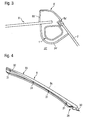
- FIG. 3 shows a substantially corresponding to the figure embodiment, in which case the A-pillar 1 'is formed by a tube profile. This profile is to the passenger compartment 22 'of an inside cover 24' covered. Laterally, the triangular window pane 2 can be seen, at the front edge of which the leg 8a 'of a panel 8' extends in the manner described above. The other leg 8b 'is similar to that in FIG FIG. 2 shown arranged and thus surrounds the lateral end of the windshield 9 '.
- FIG. 4 shows in isolation a diaphragm 8 as in the embodiment of the FIGS. 1, 2 or 3 can be used.
- the panel 8 has at its front, in the assembled state front, the engine compartment end 28 facing a flange 30, which serves for screwing to the body. Furthermore, a plurality of mounting hooks 31 can be seen, which are arranged in the vehicle outer side 32 side facing the side region 33 of the panel. They are - in the assembled state of the panel - so relatively far outward in the sloping area of the A-pillar and thus outside the immediate impact area in a collision. As a result, the endangerment of the collision victim is reduced by the mounting hooks.
- the panel 8 may preferably be made of plastic and coated on its outer, design-effective upper side 8c and / or painted.
- FIG. 5 shows the aperture 8 again (like the Figures 2 and 3 ) in cross-section to illustrate the placement and insertion of a predetermined breaking point 35.
- a clear material recess 38 can be seen in the inner region 36 of a diaphragm edge 8d. These extend along the aperture 8 in the longitudinal direction and thus substantially parallel to the respective A-pillar 1 Material recess is formed here, for example, channel-shaped.
- the panel In the event of an impact of an object or a person on the front windshield area of the vehicle, the panel would deform when exceeding a certain load at the predetermined breaking point and, for example, buckle inwards.
- the main part 8e of the diaphragm can be detached from the remaining part 8f or at least deformed by buckling. This advantageously consumes a considerable amount of the impact energy (impact energy) which occurs during the impact and causes injury. This significantly reduces the impact on the object or person.
- FIG. 6 Finally shows a mounting bracket 40 which is fixedly connected to the vehicle body, for example by riveting.
- the mounting bracket faces the mounting hooks 31 (FIG. FIG. 4 ) corresponding recesses 41, which are designed in shape so that the mounting hooks 31 can slide into the recesses and lock there.
- the mounting hooks 31 For a solid, yet releasable attachment of the panel is secured to the mounting bracket 40. This allows the panel to be replaced very easily, for example during repair after a collision.
- the diaphragm which is preferably made of plastic, can also serve the appealing design of the vehicle in a dual function and allows to maintain conventional designs of the A-pillar in shell construction or as a tube profile without significant weight increase.
Landscapes
- Engineering & Computer Science (AREA)
- Mechanical Engineering (AREA)
- Chemical & Material Sciences (AREA)
- Combustion & Propulsion (AREA)
- Transportation (AREA)
- Body Structure For Vehicles (AREA)
Description
Die Erfindung liegt auf dem Gebiet des aufprall- und crashoptimierten Designs des Frontbereichs von Kraftfahrzeugen und betrifft eine Windschutzscheibenanordnung für ein Personenkraftfahrzeug nach dem Oberbegriff des Patentanspruchs 1.The invention is in the field of impact and crash optimized design of the front area of motor vehicles and relates to a windshield assembly for a passenger vehicle according to the preamble of
Eine derartige Anordnung ist der
Die
Aus der
Dabei ist üblicherweise der Sichtbereich der seitlichen Windschutzscheibenträger (A-Säule) in die Fahrzeugseitenwand integriert und mit einer innenliegenden Verstärkung derart verschweißt, dass sich ein relativ steifes Profil bildet. Häufig vergrößert sich der Abstand zwischen den Windschutzscheibenträgern zur Motorhaube hin.In this case, usually the visual range of the lateral windshield carrier (A-pillar) is integrated into the vehicle side wall and welded to an internal reinforcement such that forms a relatively stiff profile. Frequently, the distance between the windscreen carriers increases towards the hood.
Die Fahrzeugseitenwandkontur weist aus aerodynamischen Gründen und aufgrund des Fahrzeugdesigns häufig kleine Biegeradien auf, die relativ scharfkantig sind.The vehicle side wall contour has aerodynamic reasons and due to the vehicle design often small bending radii, which are relatively sharp.
Diese Gestaltung ist im Hinblick auf das Aufprallverhalten bzw. die Gefährdung anderer Verkehrsteilnehmer nicht optimal. Bei einem frontalen Zusammenstoß - zum Beispiel bei Aufprall eines Passanten - mit dem Frontbereich des Kraftfahrzeuges besteht durch die scharfkantige Fahrzeugseitenwandkontur (A-Säule) eine erhebliche Gefährdung der Person, insbesondere im Kopfbereich.This design is not optimal with regard to the impact behavior or the endangerment of other road users. In a frontal collision - for example, in a collision of a pedestrian - with the front of the vehicle is through the sharp-edged vehicle side wall contour (A-pillar) a significant risk to the person, especially in the head area.
Der vorliegenden Erfindung liegt nun die Aufgabe zugrunde, die Windschutzscheibenanordnung eines Personenkraftfahrzeuges derart zu verbessern, dass in Aufprallsituationen, insbesondere beim Aufprall von Passanten im Windschutzscheibenbereich des Fahrzeuges, aufprallbedingte schwerwiegende Schäden weitgehend vermieden werden.The present invention is based on the object, the windshield assembly of a passenger car to be improved so that impact-related serious damage is largely avoided in impact situations, especially in the impact of passers-by in the windshield area of the vehicle.
Erfindungsgemäß wird diese Aufgabe durch eine Windschutzscheibenanordnung mit den Merkmalen des Patentanspruchs 1 gelöst.According to the invention, this object is achieved by a windshield assembly having the features of
Demgemäß ist bei einer Windschutzscheibenanordnung für ein Personenkraftfahrzeug mit einer Windschutzscheibe, die sich zwischen zwei seitlichen Windschutzscheibenträgern erstreckt, vorgesehen, dass jeder seitliche Windschutzscheibenträger frontseitig von einer Blende abgedeckt ist und dass die Blende mindestens eine Sollbruchstelle aufweist.Accordingly, in a windshield assembly for a passenger vehicle having a windshield extending between two side windshield brackets, it is provided that each side windshield support is frontally covered by a panel and that the panel has at least one predetermined breaking point.
Vorteilhafte Ausgestaltungen und Weiterbildungen der Erfindung sind Gegenstand der Unteransprüche sowie der Beschreibung unter Bezugnahme auf die Zeichnung.Advantageous embodiments and modifications of the invention are subject of the dependent claims and the description with reference to the drawing.
Die der vorliegenden Erfindung zugrunde liegende Idee besteht also unter anderem darin, bewusst eine Energie verzehrende Zone in die Blende(n) zu integrieren. Dadurch bricht bzw. kollabiert die Blende beim Auftreffen eines Gegenstandes bzw. einer Person und dem damit verbundenen Überschreiten des Belastungsschwellwertes definiert an der Sollbruchstelle. Durch die Verformung und den Bruch der Blende findet eine Energieabsorption statt, die die Aufprallenergie zumindest teilweise verzehrt und so etwaige Schäden an Personen oder Gegenständen bzw. an dem Personenkraftwagen selbst vermindert oder bestenfalls vermeidet.The idea underlying the present invention is, inter alia, to consciously integrate an energy-consuming zone into the diaphragm (s). As a result, the diaphragm breaks or collapses upon impact of an object or a person and the associated exceeding of the load threshold defined at the predetermined breaking point. Due to the deformation and the breakage of the diaphragm, an energy absorption takes place, which at least partially consumes the impact energy and thus reduces or at best avoids any damage to persons or objects or to the passenger car itself.
Dabei kann die Windschutzscheibenträgerkonstruktion an sich in üblicher Bauweise, insbesondere in sogenannter Schalenbauweise oder auch als Rohrprofil, ausgeführt sein.In this case, the windshield support structure per se in conventional construction, in particular in so-called shell construction or as a pipe profile, executed.
Ein wesentlicher Vorteil der erfindungsgemäßen Windschutzscheibenanordnung besteht damit darin, dass unter Verwendung üblicher, bewährter Fahrzeugkonstruktionen zumindest ein erheblicher Anteil der auf die Aufprallbeteiligten wirkenden Aufprallkräfte dadurch absorbiert wird, dass die Blende an ihrer mindestens einen Sollbruchstelle bricht. Durch entsprechende Materialwahl und/oder Beschichtung der Blende und/oder Anordnung der Sollbruchstelle kann dafür gesorgt werden, dass beim Sollbruch nach außen hin keine scharfen, ein zusätzliches Verletzungsrisiko darstellenden Bruchkanten entstehen.An essential advantage of the windshield assembly according to the invention is thus that under Using conventional, proven vehicle designs at least a significant proportion of impact forces acting on the impact force is absorbed by the fact that the panel breaks at its at least one predetermined breaking point. By appropriate choice of material and / or coating of the diaphragm and / or arrangement of the predetermined breaking point, care can be taken to ensure that no sharp, an additional risk of injury representing breaking edges occur during the predetermined breakage to the outside.
Die Sollbruchstelle besteht aus mindestens einer Ausnehmung im Material der Blende.The predetermined breaking point consists of at least one recess in the material of the diaphragm.
Vorzugsweise erstreckt sich die Sollbruchstelle bzw. die Materialausnehmung in Richtung des Windschutzscheibenträgers, also im Wesentlichen zwischen Dachbereich und Motorbereich des Fahrzeuges.Preferably, the predetermined breaking point or the material recess extends in the direction of the windshield carrier, ie substantially between the roof area and the engine area of the vehicle.
Nach einer weiteren vorteilhaften Ausgestaltung der Erfindung ist die Sollbruchstelle in einem innenseitigen Bereich der Blende ausgebildet, und zwar bevorzugt entlang einer Blendenkante. Die Sollbruchstelle kann dabei bevorzugt rinnen- oder nutförmig sein.According to a further advantageous embodiment of the invention, the predetermined breaking point is formed in an inner side region of the diaphragm, preferably along a diaphragm edge. The predetermined breaking point can preferably be channel-shaped or groove-shaped.
Einen besonders effektiven energieverzehrenden Effekt hat die Blende der erfindungsgemäßen Windschutzscheibenanordnung dann, wenn nach einer bevorzugten Ausgestaltung der Erfindung sich die Windschutzscheibenträger zur Fahrzeugfront hin nicht über die Oberfläche der Windschutzscheibe hinaus erstrecken. Mit anderen Worten: Bis zum vollständigen, großflächigen Aufprall eines Gegenstandes oder einer Person auf den Windschutzscheibenbereich sind allein die Blenden als energieverzehrende Elemente wirksam, so dass kein isolierter, verletzungsverursachender harter Aufprall auf die den oder die Windschutzscheibenträger erfolgen kann.A particularly effective energy-absorbing effect has the aperture of the windshield assembly according to the invention when, according to a preferred embodiment of the invention, the windshield support to the vehicle front not extend beyond the surface of the windshield out. In other words: Until the complete, large-scale impact of an object or a person on the windshield area alone the panels are energy-consuming Elements effective, so that no isolated, injury-causing hard impact on the windshield or the carrier can take place.
Montagetechnisch bevorzugt ist die Blende an einem karosserieseitigen Montageträger befestigt. Der Montageträger kann vorzugsweise aus Blech oder Kunststoff gefertigt sein und sowohl im Rohbau oder erst in der Endmontage an dem Windschutzscheibenträger (A-Säulenstruktur) befestigt werden. Die Befestigung des Montageträgers an der Karosserie erfolgt bevorzugt mittels Nietverbindungen.Mounting technology preferred, the panel is attached to a body-side mounting bracket. The mounting bracket may preferably be made of sheet metal or plastic and both in the shell or only in the final assembly to the windshield support (A-pillar structure) are attached. The attachment of the mounting bracket to the body is preferably carried out by means of riveted joints.
Nach einer für die Montage und den etwaigen Austausch der Blende bevorzugten Ausgestaltung der Erfindung weist der Montageträger mehrere Ausnehmungen auf, in die korrespondierende Montagehaken der Blende eingreifen. Dabei können die Montagehaken vorzugsweise in den korrespondierenden Ausnehmungen verrasten, so dass die Blende fest von dem Montageträger gehalten ist. Um ein ungewolltes Lösen der Blende zu verhindern, kann diese zusätzlich - bevorzugt im vorderen Fahrzeugbereich beispielsweise unterhalb des Wasserabweisers - mit der Fahrzeugkarosserie verbunden, beispielsweise verschraubt werden.After a preferred for the assembly and the possible replacement of the panel embodiment of the invention, the mounting bracket has a plurality of recesses, engage in the corresponding mounting hook of the panel. In this case, the mounting hooks can preferably engage in the corresponding recesses, so that the panel is firmly held by the mounting bracket. In order to prevent accidental release of the panel, this can additionally - preferably in the front area of the vehicle, for example, below the Wasserabweisers - connected to the vehicle body, for example, be screwed.
Nach einer vorteilhaften Fortbildung der Erfindung sind die Montagehaken im zur Fahrzeugaußenseite hin weisenden, seitlichen Bereich der Blende angeordnet. Sie befinden sich damit relativ weit außen im abfallenden Bereich der Windschutzscheibenträger (d.h. der A-Säulenkontur). Damit sind sie außerhalb des unmittelbaren Aufschlagbereiches bei einem Personenaufprall angeordnet, wodurch die Gefährdung des Aufprallopfers durch die Montagehaken weiter vermindert ist.According to an advantageous development of the invention, the mounting hooks are arranged in the vehicle outer side facing, lateral area of the panel. You are thus relatively far out in the sloping area of the windshield carrier (ie the A-pillar contour). So they are located outside the immediate impact area in a collision, whereby the endangerment of Aufprallopfers is further reduced by the mounting hooks.
Zur Gewichtsersparnis und um ein variables Design mit einfachen Mitteln zu realisieren, ist die Blende bevorzugt aus Kunststoff hergestellt.To save weight and to realize a variable design with simple means, the aperture is preferably made of plastic.
Die Erfindung wird nachfolgend anhand der in den schematischen Figuren der Zeichnung angegebenen Ausführungsbeispiele näher erläutert. Es zeigen dabei:
Figur 1- in Seitenansicht schematisch eine Karosserieseite;
Figur 2- ein erstes Ausführungsbeispiel einer erfindungsgemäßen Windschutzscheibenanordnung;
Figur 3- ein zweites Ausführungsbeispiel einer erfindungsgemäßen Windschutzscheibenanordnung;
- Figur 4
- in Seitenansicht von innen eine Kunststoffblende;
- Figur 5
- die Kunststoffblende im Querschnitt und
- Figur 6
- einen Montageträger.
- FIG. 1
- in side view schematically a body side;
- FIG. 2
- a first embodiment of a windshield assembly according to the invention;
- FIG. 3
- A second embodiment of a windshield assembly according to the invention;
- FIG. 4
- in side view from inside a plastic panel;
- FIG. 5
- the plastic cover in cross-section and
- FIG. 6
- a mounting bracket.
In allen Figuren der Zeichnung sind gleiche bzw. funktionsgleiche Elemente und Merkmale - sofern nichts Anderes angegeben ist - mit denselben Bezugszeichen versehen worden.In all figures of the drawing are the same or functionally identical elements and features - if nothing else is indicated - have been provided with the same reference numerals.
Die andere, in
Jede A-Säule 1 ist zur Frontseite 3 hin mit jeweils einer Blende 8 abgedeckt (in
Die
Wie
Zur Minderung dieser Aufprallfolgen bzw. Gefahren ist die A-Säule (Windschutzscheibenträger 1) von der Blende 8 abgedeckt, die sich mit einem Schenkel 8a entlang der Aufnahme 19 für das Dreieckfenster 2 und mit einem anderen Schenkel 8b annähernd rechtwinklig zur Windschutzscheibe 9 und im Wesentlichen entlang der A-Säule 1 erstreckt. Zur Windschutzscheibe 9 hin ist eine Zierleiste 20 vorgesehen. Zum Fahrgastraum 22 hin ist die A-Säule 1 von einer inneren Säulenverkleidung 24 verdeckt.To reduce this impact consequences or dangers, the A-pillar (windshield support 1) is covered by the
Im montierten Zustand überragt die in den Windschutzscheibenrahmen 5 eingebrachte, beispielsweise eingeklebte Windschutzscheibe 9 mit ihrer außenseitigen Oberfläche 9a die seitlichen A-Säulen 1 nicht. Mit anderen Worten: Die A-Säulen erstrecken sich zurückgesetzt hinter der Windschutzscheibenaußenseite.When mounted, the windshield frame 5 which is introduced into the windshield frame 5, for example glued in, projects beyond the lateral A-pillars 1 with its
Im Falle eines Aufpralls eines Gegenstandes oder einer Person auf den frontseitigen Windschutzscheibenbereich des Fahrzeuges würde sich die Blende beim Überschreiten einer bestimmten Belastung an der Sollbruchstelle deformieren und beispielsweise nach innen einknicken. Je nach Ausführung der Sollbruchstelle kann sich dabei der Hauptteil 8e der Blende von dem übrigen Teil 8f lösen oder aber zumindest durch Einknicken verformen. Damit wird in vorteilhafter Weise ein erheblicher Betrag der beim Aufprall auftretenden und für Verletzungen ursächlichen Aufprallenergie (Stoßenergie) verzehrt. Damit mindert sich der Aufprall für den Gegenstand bzw. die Person ganz wesentlich.In the event of an impact of an object or a person on the front windshield area of the vehicle, the panel would deform when exceeding a certain load at the predetermined breaking point and, for example, buckle inwards. Depending on the design of the predetermined breaking point, the
Mit der erfindungsgemäßen Windschutzscheibenanordnung wird im Kollisionsfall ein erheblicher Betrag der Aufprallenergie durch gezielte Deformation der Blende absorbiert, so dass die Aufprallfolgen bzw. Verletzungen zumindest vermindert werden können. Die vorzugsweise aus Kunststoff bestehende Blende kann dabei in Doppelfunktion auch dem ansprechenden Design des Fahrzeuges dienen und erlaubt ohne signifikante Gewichtserhöhung, übliche Konstruktionen der A-Säule in Schalenbauweise oder als Rohrprofil beizubehalten.With the windshield assembly according to the invention, a considerable amount of the impact energy is absorbed by targeted deformation of the diaphragm in the event of a collision, so that the impact consequences or injuries can at least be reduced. The diaphragm, which is preferably made of plastic, can also serve the appealing design of the vehicle in a dual function and allows to maintain conventional designs of the A-pillar in shell construction or as a tube profile without significant weight increase.
Obgleich die vorliegende Erfindung vorstehend anhand bevorzugter Ausführungsbeispiele beschrieben wurde, ist sie nicht darauf beschränkt, sondern auf vielfältige Art und Weise modifizierbar, ohne dass vom grundlegenden Prinzip der Erfindung abgewichen wird.Although the present invention has been described above with reference to preferred embodiments, it is not limited thereto, but modifiable in many ways, without departing from the basic principle of the invention.
So ist die Erfindung nicht auf den in den vorstehenden Figuren dargestellten, speziellen Aufbau der A-Säule mit zwei Teilträgern beschränkt.Thus, the invention is not limited to the illustrated in the preceding figures, special construction of the A-pillar with two sub-carriers.
- 11
- WindschutzscheibenträgerWindscreen beam
- 1'1'
- A-SäuleA column
- 1a, 1b1a, 1b
- Teilträgersubcarrier
- 22
- Dreiecksfensterquarterlight
- 33
- frontseitiger Bereichfrontal area
- 44
- Dachbereichroof
- 55
- WindschutzscheibenrahmenWindshield frame
- 88th
- Blendecover
- 8'8th'
- Blendecover
- 8a8a
- Schenkelleg
- 8a'8a '
- Schenkelleg
- 8b8b
- Schenkelleg
- 8b'8b '
- Schenkelleg
- 8c8c
- Oberseitetop
- 8d8d
- Blendenkantediaphragm edge
- 8e8e
- HauptteilBulk
- 8f8f
- Teilpart
- 99
- WindschutzscheibeWindshield
- 9'9 '
- WindschutzscheibeWindshield
- 9a9a
- Oberflächesurface
- 1010
- Abstanddistance
- 1111
- Halbschalehalf shell
- 1212
- SeitenwandSide wall
- 1414
- Profilsprofile
- 1919
- Aufnahmeadmission
- 2020
- Zierleistemolding
- 2222
- Fahrgastraumpassenger compartment
- 22'22 '
- Fahrgastraumpassenger compartment
- 2424
- Säulenverkleidungpillar trim
- 24'24 '
- Abdeckungcover
- 2828
- EndeThe End
- 3030
- Flanschflange
- 3131
- Montagehakenmounting hooks
- 3232
- FahrzeugaußenseiteVehicle exterior
- 3333
- BereichArea
- 3535
- SollbruchstelleBreaking point
- 3636
- BereichArea
- 3838
- Materialausnehmungmaterial recess
- 4040
- Montageträgermounting bracket
- 4141
- Ausnehmungenrecesses
Claims (11)
- A windshield arrangement for a passenger car with a windshield (9) which extends between two lateral windshield supports (1),- with each lateral windshield support (1) being covered on the front side by a cover (8), characterized in that- the cover (8) comprises a crush zone in which at least one predetermined breaking point (35) is provided at which the cover will break or collapse in a defined manner upon impact of an object and the resulting exceeding of a loading threshold, with the predetermined breaking point (35) consisting of at least one material recess (38) in the material of the cover (8).
- A windshield arrangement according to claim 1, characterized in that the predetermined breaking point (35) substantially extends along the windshield support (1).
- A windshield arrangement according to claim 2, characterized in that the predetermined breaking point (35) is arranged in the area (36) of an edge (8d) of the cover (8) which is disposed on the inside of the cover (8).
- A windshield arrangement according to at least one of the preceding claims, characterized in that the predetermined breaking point (35) is shaped in the manner of a groove or conduit.
- A windshield arrangement according to at least one of the preceding claims, characterized in that the windshield supports (1) do not extend beyond the surface (9a) of the windshield (9) in the direction towards the front of the vehicle (3).
- A windshield arrangement according to at least one of the preceding claims, characterized in that the cover (8) is fastened to a body-side mounting support (40).
- A windshield arrangement according to claim 6, characterized in that the mounting support (40) is connected with the car body by rivets.
- A windshield arrangement according to at least one of the claims 6 or 7, characterized in that the mounting support (40) comprises several recesses (41) into which the corresponding mounting hooks (31) of the cover (8) engage.
- A windshield arrangement according to claim 8, characterized in that the mounting hooks (31) latch into the respectively corresponding recesses (41).
- A windshield arrangement according to claim 8 or 9, characterized in that the mounting hooks (31) are arranged in the lateral region (33) of the cover (8) which faces to the outside of the vehicle.
- A windshield arrangement according to at least one of the preceding claims, characterized in that the cover (8) consists of plastic.
Applications Claiming Priority (1)
| Application Number | Priority Date | Filing Date | Title |
|---|---|---|---|
| DE200510049945 DE102005049945A1 (en) | 2005-10-19 | 2005-10-19 | Windshield assembly |
Publications (2)
| Publication Number | Publication Date |
|---|---|
| EP1777145A1 EP1777145A1 (en) | 2007-04-25 |
| EP1777145B1 true EP1777145B1 (en) | 2012-06-27 |
Family
ID=37654903
Family Applications (1)
| Application Number | Title | Priority Date | Filing Date |
|---|---|---|---|
| EP20060021586 Not-in-force EP1777145B1 (en) | 2005-10-19 | 2006-10-14 | Windscreen arrangement |
Country Status (2)
| Country | Link |
|---|---|
| EP (1) | EP1777145B1 (en) |
| DE (1) | DE102005049945A1 (en) |
Families Citing this family (2)
| Publication number | Priority date | Publication date | Assignee | Title |
|---|---|---|---|---|
| DE102009057943A1 (en) | 2009-12-11 | 2011-06-16 | GM Global Technology Operations LLC, ( n. d. Ges. d. Staates Delaware ), Detroit | Body structural column for a motor vehicle and motor vehicle comprising a body structural column |
| JP7338498B2 (en) * | 2020-02-10 | 2023-09-05 | トヨタ自動車株式会社 | Vehicle pillar structure |
Family Cites Families (12)
| Publication number | Priority date | Publication date | Assignee | Title |
|---|---|---|---|---|
| DE2336375A1 (en) * | 1973-07-17 | 1974-02-21 | Nissan Motor | WINDSHIELD MOUNTING |
| DE3836687C2 (en) * | 1988-10-28 | 1995-11-09 | Audi Ag | Roof molding for a motor vehicle |
| GB2293798B (en) * | 1994-10-07 | 1998-03-04 | Toyota Motor Co Ltd | Occupant protecting structures of vehicle body upper portions |
| DE19506160B4 (en) * | 1995-02-22 | 2006-05-11 | Adam Opel Ag | Frame construction for motor vehicles |
| DE60007774T2 (en) * | 1999-10-28 | 2004-10-21 | Toyota Motor Co Ltd | STRUCTURE OF A PILLAR FOR MOTOR VEHICLES |
| JP2001163054A (en) * | 1999-12-03 | 2001-06-19 | Honda Motor Co Ltd | Front door moving structure and door glass lowering structure for vehicle |
| DE10106149A1 (en) * | 2001-02-10 | 2002-09-12 | Bayerische Motoren Werke Ag | Center pillar of a motor vehicle body |
| US6415883B1 (en) * | 2002-01-24 | 2002-07-09 | Ford Global Technologies, Inc. | Deployable A-pillar covers for pedestrian protection |
| JP2004338676A (en) * | 2003-05-19 | 2004-12-02 | Takata Corp | Outer surface development type air bag device |
| DE10335030A1 (en) * | 2003-07-31 | 2005-03-03 | Daimlerchrysler Ag | Side wall for motor vehicle body has mainly vertical connection flange to roof connected to body-sided flanges, and one wall section with planking, one without |
| FR2859444B1 (en) * | 2003-09-09 | 2006-02-03 | Plastic Omnium Cie | USE OF A FENDER AND A HOOD IN COMBINATION WITH AN AIRBAG, RESTRAINT AND WING SUPPORT, WING, WING MODULE AND HOOD OF A MOTOR VEHICLE |
| DE202004010601U1 (en) * | 2004-04-08 | 2005-05-19 | Dura Automotive Plettenberg Entwicklungs- Und Vertriebs Gmbh | Pillar cover made of plastic for fixing on a vehicle or on a vehicle door comprises a U-shaped holder for an adjoining component and/or is provided with a soft plastic component and/or a fixing element integrated in the pillar cover |
-
2005
- 2005-10-19 DE DE200510049945 patent/DE102005049945A1/en not_active Ceased
-
2006
- 2006-10-14 EP EP20060021586 patent/EP1777145B1/en not_active Not-in-force
Also Published As
| Publication number | Publication date |
|---|---|
| EP1777145A1 (en) | 2007-04-25 |
| DE102005049945A1 (en) | 2007-04-26 |
Similar Documents
| Publication | Publication Date | Title |
|---|---|---|
| EP1840002B1 (en) | Motor vehicle with a deformable element for absorbing side impact forces in the side region of the vehicle | |
| EP1981737B1 (en) | Energy-absorption element, device for protecting against an impact, motor vehicle inner pannelling component and crossmember | |
| EP3668777B1 (en) | Vehicle longitudinal beam arrangement | |
| EP2046627B1 (en) | Side sill of a body of a motor vehicle | |
| EP1840005B1 (en) | Vehicle body with cross member structure for a seat area in the vehicle | |
| EP0426648B1 (en) | Vehicle door for motor-car | |
| DE19934141A1 (en) | Bumper support for improved pedestrian protection in motor vehicles | |
| DE102004007571B4 (en) | Front end for a vehicle, in particular for a motor vehicle | |
| DE102008009088B4 (en) | Body of a motor vehicle with a side skirts | |
| DE102006030504B4 (en) | Bumper for a motor vehicle | |
| DE102007014391B4 (en) | Side impact protection device installed between inner and outer panels | |
| EP1300323A2 (en) | Vehicle body element with a large surface | |
| EP1777145B1 (en) | Windscreen arrangement | |
| DE10305652A1 (en) | frontend area | |
| EP2239128B1 (en) | Vehicle component with structural reinforcement section | |
| EP1216891A2 (en) | Energy absorbing deformation element | |
| DE102012020865A1 (en) | Motor vehicle chassis has reinforcing portions that are branched from front portion and extended on passenger compartment toward the side of end wall to lateral wall portions | |
| DE202015001448U1 (en) | Vehicle column, in particular A-pillar for a motor vehicle | |
| DE102009040602A1 (en) | Bumpers and bumper kit | |
| DE102009012941A1 (en) | Safety device for use in nose of body of passenger car for protecting pedestrian, during collision or off-set crash in low speed range, has additional deformation element provided between fairing unit and mounting carrier | |
| DE102004009665B4 (en) | A-pillar for a motor vehicle body | |
| DE10309958A1 (en) | Automobile with pedestrian protection device using deformation element bridged by releasable blocking device supporting front hood and/or adjacent body component during normal driving | |
| DE102006015402B4 (en) | Front hood for a passenger car | |
| DE102010036985A1 (en) | Deformation element for use in arrangement between interior lining section and body of vehicle, is formed as one-sided open hollow profile which is fixed at inner side of interior lining section in stationary manner | |
| DE102006015409B4 (en) | Front hood for a passenger car |
Legal Events
| Date | Code | Title | Description |
|---|---|---|---|
| PUAI | Public reference made under article 153(3) epc to a published international application that has entered the european phase |
Free format text: ORIGINAL CODE: 0009012 |
|
| AK | Designated contracting states |
Kind code of ref document: A1 Designated state(s): AT BE BG CH CY CZ DE DK EE ES FI FR GB GR HU IE IS IT LI LT LU LV MC NL PL PT RO SE SI SK TR |
|
| AX | Request for extension of the european patent |
Extension state: AL BA HR MK YU |
|
| 17P | Request for examination filed |
Effective date: 20071025 |
|
| AKX | Designation fees paid |
Designated state(s): AT BE BG CH CY CZ DE DK EE ES FI FR GB GR HU IE IS IT LI LT LU LV MC NL PL PT RO SE SI SK TR |
|
| 17Q | First examination report despatched |
Effective date: 20071218 |
|
| RAP1 | Party data changed (applicant data changed or rights of an application transferred) |
Owner name: GM GLOBAL TECHNOLOGY OPERATIONS LLC |
|
| GRAP | Despatch of communication of intention to grant a patent |
Free format text: ORIGINAL CODE: EPIDOSNIGR1 |
|
| GRAS | Grant fee paid |
Free format text: ORIGINAL CODE: EPIDOSNIGR3 |
|
| GRAA | (expected) grant |
Free format text: ORIGINAL CODE: 0009210 |
|
| AK | Designated contracting states |
Kind code of ref document: B1 Designated state(s): AT BE BG CH CY CZ DE DK EE ES FI FR GB GR HU IE IS IT LI LT LU LV MC NL PL PT RO SE SI SK TR |
|
| REG | Reference to a national code |
Ref country code: GB Ref legal event code: FG4D Free format text: NOT ENGLISH |
|
| REG | Reference to a national code |
Ref country code: CH Ref legal event code: EP |
|
| REG | Reference to a national code |
Ref country code: AT Ref legal event code: REF Ref document number: 564026 Country of ref document: AT Kind code of ref document: T Effective date: 20120715 |
|
| REG | Reference to a national code |
Ref country code: IE Ref legal event code: FG4D Free format text: LANGUAGE OF EP DOCUMENT: GERMAN |
|
| REG | Reference to a national code |
Ref country code: DE Ref legal event code: R096 Ref document number: 502006011645 Country of ref document: DE Effective date: 20120823 |
|
| PG25 | Lapsed in a contracting state [announced via postgrant information from national office to epo] |
Ref country code: FI Free format text: LAPSE BECAUSE OF FAILURE TO SUBMIT A TRANSLATION OF THE DESCRIPTION OR TO PAY THE FEE WITHIN THE PRESCRIBED TIME-LIMIT Effective date: 20120627 Ref country code: LT Free format text: LAPSE BECAUSE OF FAILURE TO SUBMIT A TRANSLATION OF THE DESCRIPTION OR TO PAY THE FEE WITHIN THE PRESCRIBED TIME-LIMIT Effective date: 20120627 Ref country code: SE Free format text: LAPSE BECAUSE OF FAILURE TO SUBMIT A TRANSLATION OF THE DESCRIPTION OR TO PAY THE FEE WITHIN THE PRESCRIBED TIME-LIMIT Effective date: 20120627 |
|
| REG | Reference to a national code |
Ref country code: NL Ref legal event code: VDEP Effective date: 20120627 |
|
| REG | Reference to a national code |
Ref country code: LT Ref legal event code: MG4D Effective date: 20120627 |
|
| PG25 | Lapsed in a contracting state [announced via postgrant information from national office to epo] |
Ref country code: SI Free format text: LAPSE BECAUSE OF FAILURE TO SUBMIT A TRANSLATION OF THE DESCRIPTION OR TO PAY THE FEE WITHIN THE PRESCRIBED TIME-LIMIT Effective date: 20120627 Ref country code: LV Free format text: LAPSE BECAUSE OF FAILURE TO SUBMIT A TRANSLATION OF THE DESCRIPTION OR TO PAY THE FEE WITHIN THE PRESCRIBED TIME-LIMIT Effective date: 20120627 Ref country code: GR Free format text: LAPSE BECAUSE OF FAILURE TO SUBMIT A TRANSLATION OF THE DESCRIPTION OR TO PAY THE FEE WITHIN THE PRESCRIBED TIME-LIMIT Effective date: 20120928 |
|
| PG25 | Lapsed in a contracting state [announced via postgrant information from national office to epo] |
Ref country code: EE Free format text: LAPSE BECAUSE OF FAILURE TO SUBMIT A TRANSLATION OF THE DESCRIPTION OR TO PAY THE FEE WITHIN THE PRESCRIBED TIME-LIMIT Effective date: 20120627 Ref country code: CZ Free format text: LAPSE BECAUSE OF FAILURE TO SUBMIT A TRANSLATION OF THE DESCRIPTION OR TO PAY THE FEE WITHIN THE PRESCRIBED TIME-LIMIT Effective date: 20120627 Ref country code: SK Free format text: LAPSE BECAUSE OF FAILURE TO SUBMIT A TRANSLATION OF THE DESCRIPTION OR TO PAY THE FEE WITHIN THE PRESCRIBED TIME-LIMIT Effective date: 20120627 Ref country code: RO Free format text: LAPSE BECAUSE OF FAILURE TO SUBMIT A TRANSLATION OF THE DESCRIPTION OR TO PAY THE FEE WITHIN THE PRESCRIBED TIME-LIMIT Effective date: 20120627 Ref country code: IS Free format text: LAPSE BECAUSE OF FAILURE TO SUBMIT A TRANSLATION OF THE DESCRIPTION OR TO PAY THE FEE WITHIN THE PRESCRIBED TIME-LIMIT Effective date: 20121027 Ref country code: CY Free format text: LAPSE BECAUSE OF FAILURE TO SUBMIT A TRANSLATION OF THE DESCRIPTION OR TO PAY THE FEE WITHIN THE PRESCRIBED TIME-LIMIT Effective date: 20120627 |
|
| PG25 | Lapsed in a contracting state [announced via postgrant information from national office to epo] |
Ref country code: PL Free format text: LAPSE BECAUSE OF FAILURE TO SUBMIT A TRANSLATION OF THE DESCRIPTION OR TO PAY THE FEE WITHIN THE PRESCRIBED TIME-LIMIT Effective date: 20120627 Ref country code: IT Free format text: LAPSE BECAUSE OF FAILURE TO SUBMIT A TRANSLATION OF THE DESCRIPTION OR TO PAY THE FEE WITHIN THE PRESCRIBED TIME-LIMIT Effective date: 20120627 Ref country code: PT Free format text: LAPSE BECAUSE OF FAILURE TO SUBMIT A TRANSLATION OF THE DESCRIPTION OR TO PAY THE FEE WITHIN THE PRESCRIBED TIME-LIMIT Effective date: 20121029 |
|
| PG25 | Lapsed in a contracting state [announced via postgrant information from national office to epo] |
Ref country code: NL Free format text: LAPSE BECAUSE OF FAILURE TO SUBMIT A TRANSLATION OF THE DESCRIPTION OR TO PAY THE FEE WITHIN THE PRESCRIBED TIME-LIMIT Effective date: 20120627 |
|
| BERE | Be: lapsed |
Owner name: GM GLOBAL TECHNOLOGY OPERATIONS LLC Effective date: 20121031 |
|
| PG25 | Lapsed in a contracting state [announced via postgrant information from national office to epo] |
Ref country code: ES Free format text: LAPSE BECAUSE OF FAILURE TO SUBMIT A TRANSLATION OF THE DESCRIPTION OR TO PAY THE FEE WITHIN THE PRESCRIBED TIME-LIMIT Effective date: 20121008 Ref country code: DK Free format text: LAPSE BECAUSE OF FAILURE TO SUBMIT A TRANSLATION OF THE DESCRIPTION OR TO PAY THE FEE WITHIN THE PRESCRIBED TIME-LIMIT Effective date: 20120627 |
|
| PLBE | No opposition filed within time limit |
Free format text: ORIGINAL CODE: 0009261 |
|
| STAA | Information on the status of an ep patent application or granted ep patent |
Free format text: STATUS: NO OPPOSITION FILED WITHIN TIME LIMIT |
|
| PG25 | Lapsed in a contracting state [announced via postgrant information from national office to epo] |
Ref country code: MC Free format text: LAPSE BECAUSE OF NON-PAYMENT OF DUE FEES Effective date: 20121031 |
|
| REG | Reference to a national code |
Ref country code: CH Ref legal event code: PL |
|
| 26N | No opposition filed |
Effective date: 20130328 |
|
| REG | Reference to a national code |
Ref country code: IE Ref legal event code: MM4A |
|
| REG | Reference to a national code |
Ref country code: DE Ref legal event code: R097 Ref document number: 502006011645 Country of ref document: DE Effective date: 20130328 |
|
| PG25 | Lapsed in a contracting state [announced via postgrant information from national office to epo] |
Ref country code: IE Free format text: LAPSE BECAUSE OF NON-PAYMENT OF DUE FEES Effective date: 20121014 Ref country code: BE Free format text: LAPSE BECAUSE OF NON-PAYMENT OF DUE FEES Effective date: 20121031 Ref country code: BG Free format text: LAPSE BECAUSE OF FAILURE TO SUBMIT A TRANSLATION OF THE DESCRIPTION OR TO PAY THE FEE WITHIN THE PRESCRIBED TIME-LIMIT Effective date: 20120927 Ref country code: CH Free format text: LAPSE BECAUSE OF NON-PAYMENT OF DUE FEES Effective date: 20121031 Ref country code: LI Free format text: LAPSE BECAUSE OF NON-PAYMENT OF DUE FEES Effective date: 20121031 |
|
| REG | Reference to a national code |
Ref country code: AT Ref legal event code: MM01 Ref document number: 564026 Country of ref document: AT Kind code of ref document: T Effective date: 20121031 |
|
| PG25 | Lapsed in a contracting state [announced via postgrant information from national office to epo] |
Ref country code: AT Free format text: LAPSE BECAUSE OF NON-PAYMENT OF DUE FEES Effective date: 20121031 |
|
| PG25 | Lapsed in a contracting state [announced via postgrant information from national office to epo] |
Ref country code: TR Free format text: LAPSE BECAUSE OF FAILURE TO SUBMIT A TRANSLATION OF THE DESCRIPTION OR TO PAY THE FEE WITHIN THE PRESCRIBED TIME-LIMIT Effective date: 20120627 |
|
| PG25 | Lapsed in a contracting state [announced via postgrant information from national office to epo] |
Ref country code: LU Free format text: LAPSE BECAUSE OF NON-PAYMENT OF DUE FEES Effective date: 20121014 |
|
| PG25 | Lapsed in a contracting state [announced via postgrant information from national office to epo] |
Ref country code: HU Free format text: LAPSE BECAUSE OF FAILURE TO SUBMIT A TRANSLATION OF THE DESCRIPTION OR TO PAY THE FEE WITHIN THE PRESCRIBED TIME-LIMIT Effective date: 20061014 |
|
| PGFP | Annual fee paid to national office [announced via postgrant information from national office to epo] |
Ref country code: GB Payment date: 20151014 Year of fee payment: 10 |
|
| REG | Reference to a national code |
Ref country code: FR Ref legal event code: PLFP Year of fee payment: 11 |
|
| PGFP | Annual fee paid to national office [announced via postgrant information from national office to epo] |
Ref country code: FR Payment date: 20160919 Year of fee payment: 11 |
|
| GBPC | Gb: european patent ceased through non-payment of renewal fee |
Effective date: 20161014 |
|
| PG25 | Lapsed in a contracting state [announced via postgrant information from national office to epo] |
Ref country code: GB Free format text: LAPSE BECAUSE OF NON-PAYMENT OF DUE FEES Effective date: 20161014 |
|
| REG | Reference to a national code |
Ref country code: FR Ref legal event code: ST Effective date: 20180629 |
|
| PG25 | Lapsed in a contracting state [announced via postgrant information from national office to epo] |
Ref country code: FR Free format text: LAPSE BECAUSE OF NON-PAYMENT OF DUE FEES Effective date: 20171031 |
|
| PGFP | Annual fee paid to national office [announced via postgrant information from national office to epo] |
Ref country code: DE Payment date: 20181002 Year of fee payment: 13 |
|
| REG | Reference to a national code |
Ref country code: DE Ref legal event code: R119 Ref document number: 502006011645 Country of ref document: DE |
|
| PG25 | Lapsed in a contracting state [announced via postgrant information from national office to epo] |
Ref country code: DE Free format text: LAPSE BECAUSE OF NON-PAYMENT OF DUE FEES Effective date: 20200501 |