EP1772332A1 - Dispositif de support d'un essuie-glace - Google Patents
Dispositif de support d'un essuie-glace Download PDFInfo
- Publication number
- EP1772332A1 EP1772332A1 EP04022356A EP04022356A EP1772332A1 EP 1772332 A1 EP1772332 A1 EP 1772332A1 EP 04022356 A EP04022356 A EP 04022356A EP 04022356 A EP04022356 A EP 04022356A EP 1772332 A1 EP1772332 A1 EP 1772332A1
- Authority
- EP
- European Patent Office
- Prior art keywords
- disc
- rotation
- axis
- vehicle
- recess
- Prior art date
- Legal status (The legal status is an assumption and is not a legal conclusion. Google has not performed a legal analysis and makes no representation as to the accuracy of the status listed.)
- Granted
Links
- 238000007789 sealing Methods 0.000 claims description 25
- 238000004140 cleaning Methods 0.000 claims description 7
- 239000000853 adhesive Substances 0.000 claims description 4
- 230000001070 adhesive effect Effects 0.000 claims description 4
- 239000007788 liquid Substances 0.000 claims description 4
- 238000011144 upstream manufacturing Methods 0.000 claims description 2
- 239000011521 glass Substances 0.000 description 19
- 239000012530 fluid Substances 0.000 description 2
- 230000001681 protective effect Effects 0.000 description 2
- 238000010521 absorption reaction Methods 0.000 description 1
- 230000006978 adaptation Effects 0.000 description 1
- 230000000712 assembly Effects 0.000 description 1
- 238000000429 assembly Methods 0.000 description 1
- 238000013016 damping Methods 0.000 description 1
- 230000001419 dependent effect Effects 0.000 description 1
- 238000011161 development Methods 0.000 description 1
- 230000018109 developmental process Effects 0.000 description 1
- 230000000694 effects Effects 0.000 description 1
- 230000001771 impaired effect Effects 0.000 description 1
- 230000003287 optical effect Effects 0.000 description 1
- 239000002245 particle Substances 0.000 description 1
- 230000035515 penetration Effects 0.000 description 1
- 239000003566 sealing material Substances 0.000 description 1
- 230000007704 transition Effects 0.000 description 1
Images


Classifications
-
- B—PERFORMING OPERATIONS; TRANSPORTING
- B60—VEHICLES IN GENERAL
- B60S—SERVICING, CLEANING, REPAIRING, SUPPORTING, LIFTING, OR MANOEUVRING OF VEHICLES, NOT OTHERWISE PROVIDED FOR
- B60S1/00—Cleaning of vehicles
- B60S1/02—Cleaning windscreens, windows or optical devices
- B60S1/04—Wipers or the like, e.g. scrapers
- B60S1/043—Attachment of the wiper assembly to the vehicle
- B60S1/0436—Attachement of separate wiper shaft holders to the vehicle
-
- B—PERFORMING OPERATIONS; TRANSPORTING
- B60—VEHICLES IN GENERAL
- B60S—SERVICING, CLEANING, REPAIRING, SUPPORTING, LIFTING, OR MANOEUVRING OF VEHICLES, NOT OTHERWISE PROVIDED FOR
- B60S1/00—Cleaning of vehicles
- B60S1/02—Cleaning windscreens, windows or optical devices
- B60S1/04—Wipers or the like, e.g. scrapers
- B60S1/0452—Position of the wipers relative to the vehicle
-
- B—PERFORMING OPERATIONS; TRANSPORTING
- B60—VEHICLES IN GENERAL
- B60S—SERVICING, CLEANING, REPAIRING, SUPPORTING, LIFTING, OR MANOEUVRING OF VEHICLES, NOT OTHERWISE PROVIDED FOR
- B60S1/00—Cleaning of vehicles
- B60S1/02—Cleaning windscreens, windows or optical devices
- B60S1/04—Wipers or the like, e.g. scrapers
- B60S1/32—Wipers or the like, e.g. scrapers characterised by constructional features of wiper blade arms or blades
- B60S1/34—Wiper arms; Mountings therefor
- B60S1/3415—Wiper arms; Mountings therefor with means for supplying cleaning fluid to windscreen cleaners, e.g. washers
-
- B—PERFORMING OPERATIONS; TRANSPORTING
- B60—VEHICLES IN GENERAL
- B60S—SERVICING, CLEANING, REPAIRING, SUPPORTING, LIFTING, OR MANOEUVRING OF VEHICLES, NOT OTHERWISE PROVIDED FOR
- B60S1/00—Cleaning of vehicles
- B60S1/02—Cleaning windscreens, windows or optical devices
- B60S1/04—Wipers or the like, e.g. scrapers
- B60S1/32—Wipers or the like, e.g. scrapers characterised by constructional features of wiper blade arms or blades
- B60S1/34—Wiper arms; Mountings therefor
- B60S1/3488—Means for mounting wiper arms onto the vehicle
- B60S1/349—Means for mounting the wiper bearing to the vehicle body
Definitions
- the invention relates to a device for mounting a windshield wiper of a vehicle, and more particularly to a device for supporting a windshield wiper of a vehicle, which has a support arm which is attached to the vehicle roof at the proximal end and at the distal end cantilevered has an axis of rotation of the windshield wiper, wherein the axis of rotation to be wiped disc penetrates through a recess through the disc.
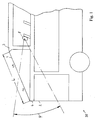
- a very flat inclined disc which has a disc length of about 2 m. If such a disc with a wiper arm to clean, so are several problems to solve. Usual Wischerarmin be about 1 m, so that when mounting the wiper arm in the region of the upper edge of the disc or the lower edge of the disc a disc with said length of about 2 m can not be completely cleaned. If a wiper arm is mounted in the region of the vehicle roof 3, see FIG. 1, then it would have to have a wiper arm length which is approximately the length L of the pane length. However, a wiper arm of such length is usually not available.
- the wiper arm is mounted with a usual length of about 1 m in the area of the front body frame 4 between the disc 1 and the driver's disc 2, so that the wiper arm can wipe the front portion 1a of the disc 1 (Wischerarmspitze is directed against the direction of travel), so Rear portion 1b of the disc 1 is not reached.
- this disadvantage may be of little importance, since the field of view ⁇ of a passenger F seen from its point of view, the rear portion 1 b of the vehicle window 1 no longer detected. If a windshield wiper arm is fastened to the body frame 4 between the disk 1 and the driver disk 2, the portion 1a of the disk 1 relevant to the field of view can thus be cleaned and wiped.
- the invention has the object to provide a device for storing a windshield wiper, so that at very flat inclined disc of the front disc area can be wiped with the windshield wiper, in the field of view of the passengers as little as possible by a windshield wiper associated drive assembly Drive motor and drive linkage is visible.
- the inventive device for supporting a windshield wiper for a vehicle has a support arm, which is attached at its proximal end to the vehicle roof, cantilevered at the distal end and at the distal end has an axis of rotation on which a windshield wiper is mounted.
- This makes it possible to clean the front disc area with the windshield wiper, wherein the support arm bridges the distance between the vehicle roof and the axis of rotation of the windshield wiper.
- the required assemblies such as drive linkage and drive motor can be mounted in a zone near the support arm or in the support arm, which zone is located in the rear of the disc. Thus, there is no obstruction of the field of view for a passenger.
- the support arm is mounted on the vehicle roof and cantilevered at its distal end, the glass pane is not loaded in the region of the recess. There is therefore no risk that the area around the recess of the disk will be overstressed due to excessive forces and moments (for example under snow load) and a breakage of the disk would result.
- the axis of rotation penetrates the disc to be wiped through a recess through the disc. This makes it possible to drive the axis of rotation from the vehicle interior.
- the support arm is arranged in the interior of the vehicle.
- the support arm and the sensitive components such as linkage and drive motor are thus safely protected from external weather conditions.
- the recess may be provided through the glass sheet at any distance from the edge of the disk. This is advantageous because thus the respective field of view is not impaired and any available wiper length can be used.
- the axis of rotation is connected by means of a sealing element with the glass pane. This is advantageous because thus the recess of the disc is sealed against external dirt or moisture.
- an intermediate disc is provided between the sealing element and the axis of rotation. This leaves it free, whether the sealing element is designed to be movable or rigid.
- the intermediate disc is rigidly connected to the glass sheet.
- the sealing element is adhesive.
- the adhesive not only fixes the washer with the glass, but also takes on a dampening function.
- the axis of rotation is connected by means of a sealing flange with the intermediate disc.
- an axial seal is provided between the sealing flange and washer. This allows an effective seal against externally acting moisture or dirt particles.
- a labyrinth seal can be provided between the sealing flange and the intermediate disc.
- the labyrinth seal is a non-contact protective seal, whereby the sealing function is achieved by a fluid throttling in the labyrinth gap.
- the labyrinth seal of the axial seal is connected upstream. Moisture acting from the outside must therefore first penetrate the labyrinth seal before it reaches the axial seal. In this embodiment, thus a very effective seal is achieved.
- a line for the window cleaning liquid is carried out through the recess of the glass pane to the outside. In cooperation with the windscreen wiper can thus achieve an effective window cleaning.
- the axis of rotation is connected to a drive linkage and a drive motor, so that the axis of rotation can be driven.
- the wiping field can be made variable.
- the device is covered to the passenger compartment by means of a cover.
- a privacy and protection against contact for the passengers is achieved.
- a monitor is connected to the cover of the device according to the invention.
- the monitor can thus be arranged at a sufficient distance from the passenger, so that the display of the monitor can be well viewed by the passenger in the first row of seats. If the monitor were mounted in the area of the vehicle roof, the distance between the passenger and the monitor would be too short.
- the vehicle having the device for mounting a windshield wiper is a bus.
- the device can be used for a panoramic window.
- FIG. 1 schematically shows a vehicle which has an upper glass pane 1 and a driver's pane 2.
- the disk 1 is inclined very flat to the horizontal, wherein it has a disk length L.
- the disc 1 has a front portion 1a and a rear portion 1b.
- the front area 1a lies in the field of view ⁇ of the passenger F, which can detect this from his eye point.
- the disk 1 is surrounded on the one hand by the vehicle roof 3 and on the other by the front body frame 4.
- the disc 1 has a front surface through which the passenger can look at the road ahead of the vehicle.
- the disc 1 is also formed so that it also has two side surfaces in addition to the front surface.
- the passenger can also view the area of the road adjacent to the left and right sides.
- FIG. 2 shows an embodiment of the device according to the invention.
- the device has a support arm 5, which is arranged in the vehicle interior and attached to its proximal end 6 on the vehicle roof 3.
- the support arm 5 protrudes without further support and thus cantilevered in the direction of the front portion 1a of the disc 1.
- an axis of rotation 8 is mounted, to which the windshield wiper 9 is mounted.
- the axis of rotation 8 penetrates the disc to be wiped 1 through a recess 10 through the disc 1. Since the support arm 5 is cantilevered, it does not support in the region of the recess 10 of the disc 1 from. Thus, the disc 1 is not burdened by the wiper arm induced forces and moments.
- the force and moment absorption takes place exclusively in the transition region of the proximal end 6 with the vehicle roof 3.
- the drive linkage 17 shown in FIG. 2 and the drive motor 18 for the windscreen wiper 9 can preferably be arranged such that it is located in the region of the support arm 5. This allows a low height can be achieved.
- the length of the support arm 5 may be designed so that with the windshield wiper 9, the entire front portion 1a of the disc 1 can wipe.
- the length of the support arm 5 is basically arbitrary, so that the position of the recess 10 in the glass pane 1 results from the length of the support arm 5 and the length of the windshield wiper 9.
- the support arm 5 can be covered with a cover 19 together with the drive linkage 17 and the drive motor 18. Preferably, this cover is no longer in the direct field of view ⁇ of the passenger F.
- this cover itself can be covered by a monitor which is connected to the cover.
- the monitor 20 e.g. a flat screen, is oriented with its display side towards the passenger interior.
- the monitor can be used to display safety advices or a television picture for entertainment to the passengers.
- FIG. 3 shows a detail of the device according to the invention.
- the axis of rotation 8 passes through the recess 10 of the glass pane 1, wherein the axis of rotation 8 is oriented perpendicular to the glass pane 1.
- an intermediate disc 12 is arranged, which is provided in its outer edge region with a sealing element 11.
- this sealing element 11 is an adhesive which fixes the position of the intermediate disc 12 with the glass pane 1 and at the same time assumes a damping function. Vibrations of the vehicle are thus not transmitted directly from the glass pane 1 on the washer 12.
- the washer 12 has a collar, on whose front side two seals are provided.
- a labyrinth seal 15 and an axial seal 14 are provided. Both seals are housed in a sealing flange 13, wherein the sealing flange 13 is fixedly connected to the axis of rotation 8.
- the sealing flange 13, the axial seal 14 and the labyrinth seal 15 thus move, the seals engaging the intermediate disk 12 on the front side of the collar.
- the sealing flange surrounds the intermediate disc collar, whereby penetration of liquid up to the seals is difficult.
- the labyrinth seal is designed axially in this embodiment.
- the labyrinth seal is a non-contact seal in which the sealing material engages in a gap which is incorporated in the collar of the intermediate disc. With a rotation of the axis of rotation occurs with correct adjustment of the labyrinth seal to no wear of the seal, whereby a high reliability in the sealing effect is achieved.
- the axial seal is oriented closer to the axis of rotation and rubbing touches the collar of the protective cover 12. This sealing system reliably prevents the ingress of dirt or moisture into the storage area of the device and thus into the interior of the vehicle.
- the receptacle for the windshield wiper 9 is attached.
- FIG. 4 shows a further embodiment of the invention.
- a conduit 16 is mounted, which can pass through the recess of the glass sheet 1 through a window cleaning liquid to the outside on the disk. For an effective cleaning of the disc 1 in cooperation with the windshield wiper 9 can be achieved.
- the conduit 16 is mounted with the washer 12 in this embodiment.
Landscapes
- Engineering & Computer Science (AREA)
- Mechanical Engineering (AREA)
- Window Of Vehicle (AREA)
- Body Structure For Vehicles (AREA)
- Fittings On The Vehicle Exterior For Carrying Loads, And Devices For Holding Or Mounting Articles (AREA)
Priority Applications (3)
| Application Number | Priority Date | Filing Date | Title |
|---|---|---|---|
| EP04022356A EP1772332B1 (fr) | 2004-09-20 | 2004-09-20 | Disposition d'essuie-glace sur un automobile |
| PL04022356T PL1772332T3 (pl) | 2004-09-20 | 2004-09-20 | Układ wycieraczki na pojeździe |
| CNB2005100076444A CN100542858C (zh) | 2004-09-20 | 2005-02-07 | 窗玻璃擦拭器的支承装置 |
Applications Claiming Priority (1)
| Application Number | Priority Date | Filing Date | Title |
|---|---|---|---|
| EP04022356A EP1772332B1 (fr) | 2004-09-20 | 2004-09-20 | Disposition d'essuie-glace sur un automobile |
Publications (2)
| Publication Number | Publication Date |
|---|---|
| EP1772332A1 true EP1772332A1 (fr) | 2007-04-11 |
| EP1772332B1 EP1772332B1 (fr) | 2012-08-08 |
Family
ID=34926622
Family Applications (1)
| Application Number | Title | Priority Date | Filing Date |
|---|---|---|---|
| EP04022356A Active EP1772332B1 (fr) | 2004-09-20 | 2004-09-20 | Disposition d'essuie-glace sur un automobile |
Country Status (3)
| Country | Link |
|---|---|
| EP (1) | EP1772332B1 (fr) |
| CN (1) | CN100542858C (fr) |
| PL (1) | PL1772332T3 (fr) |
Citations (6)
| Publication number | Priority date | Publication date | Assignee | Title |
|---|---|---|---|---|
| US2040966A (en) * | 1931-03-09 | 1936-05-19 | Murray Corp | Header construction for concealed windshield wipers |
| GB1448892A (en) * | 1974-04-29 | 1976-09-08 | Chrysler Uk | Vehicle window wipers |
| FR2673408A1 (fr) * | 1991-03-01 | 1992-09-04 | Renault | Dispositif essuie-vitre escamotable. |
| JPH11198766A (ja) * | 1998-01-19 | 1999-07-27 | Toyota Auto Body Co Ltd | ガラスハッチの開閉ノブ |
| JP2000203258A (ja) * | 1999-01-13 | 2000-07-25 | Iseki & Co Ltd | キャビンの窓ハンド |
| JP2004074940A (ja) | 2002-08-20 | 2004-03-11 | Yanmar Agricult Equip Co Ltd | トラクタの振動低減装置 |
-
2004
- 2004-09-20 EP EP04022356A patent/EP1772332B1/fr active Active
- 2004-09-20 PL PL04022356T patent/PL1772332T3/pl unknown
-
2005
- 2005-02-07 CN CNB2005100076444A patent/CN100542858C/zh active Active
Patent Citations (6)
| Publication number | Priority date | Publication date | Assignee | Title |
|---|---|---|---|---|
| US2040966A (en) * | 1931-03-09 | 1936-05-19 | Murray Corp | Header construction for concealed windshield wipers |
| GB1448892A (en) * | 1974-04-29 | 1976-09-08 | Chrysler Uk | Vehicle window wipers |
| FR2673408A1 (fr) * | 1991-03-01 | 1992-09-04 | Renault | Dispositif essuie-vitre escamotable. |
| JPH11198766A (ja) * | 1998-01-19 | 1999-07-27 | Toyota Auto Body Co Ltd | ガラスハッチの開閉ノブ |
| JP2000203258A (ja) * | 1999-01-13 | 2000-07-25 | Iseki & Co Ltd | キャビンの窓ハンド |
| JP2004074940A (ja) | 2002-08-20 | 2004-03-11 | Yanmar Agricult Equip Co Ltd | トラクタの振動低減装置 |
Non-Patent Citations (3)
| Title |
|---|
| PATENT ABSTRACTS OF JAPAN vol. 1999, no. 12 29 October 1999 (1999-10-29) * |
| PATENT ABSTRACTS OF JAPAN vol. 2000, no. 10 17 November 2000 (2000-11-17) * |
| PATENT ABSTRACTS OF JAPAN vol. 2003, no. 12 5 December 2003 (2003-12-05) * |
Also Published As
| Publication number | Publication date |
|---|---|
| CN100542858C (zh) | 2009-09-23 |
| PL1772332T3 (pl) | 2013-01-31 |
| CN1751919A (zh) | 2006-03-29 |
| EP1772332B1 (fr) | 2012-08-08 |
Similar Documents
| Publication | Publication Date | Title |
|---|---|---|
| EP1945485B1 (fr) | Systeme d'essuie-glace pour pare-brise dans des automobiles | |
| EP1529688A1 (fr) | Dispositif de caméra pour véhicules motorisés | |
| DE102008027430A1 (de) | Schutzvorrichtung für eine Bilderfassungseinheit eines Fahrzeuges | |
| DE102008026056A1 (de) | Vorrichtung zur Vergrößerung des Sehfeldes | |
| EP1714859A1 (fr) | Entraînement auxiliaire compact pour remorque | |
| DE19628181A1 (de) | Lagerung für eine Brennkraftmaschine | |
| DE3314456A1 (de) | Wischvorrichtung fuer scheiben von kraftfahrzeugen | |
| DE102011119153A1 (de) | Kardangelenkanordnung und eine kardangelenk-schutzvorrichtung | |
| EP2251229B1 (fr) | Système moniteur-caméra d'une porte de véhicule ou d'objet | |
| EP1772332B1 (fr) | Disposition d'essuie-glace sur un automobile | |
| DE4006708C2 (de) | Aufnahme für Panzerglasscheiben in einer Fahrzeugkarosserie | |
| DE3731922A1 (de) | Wischvorrichtung fuer scheiben von kraftfahrzeugen ii | |
| DE3707233A1 (de) | Scheibenwischeranlage, insbesondere fuer panoramascheiben von kraftfahrzeugen | |
| EP1238874A1 (fr) | Essuie-vitre | |
| DE602005000342T2 (de) | Vorrichtung zum Verdecken und Schützen der Scheibenwischerblätter eines Kraftfahrzeuges in der inaktiven Position | |
| EP2952421B1 (fr) | Entraînement d'assistance pour une remorque et remorque | |
| DE10348444A1 (de) | Verschwenkbares Deckelteil in einem Fahrzeug | |
| EP1245466A1 (fr) | Capot de protection pour essuie-glace | |
| DE2001556C3 (de) | Scheibenwischeranordnung für Fahrzeuge | |
| EP2076416A1 (fr) | Balai d'essuie-glace pour nettoyer une vitre | |
| DE10259562A1 (de) | Wischeranlage für ein Fahrzeug | |
| DE19835697C2 (de) | Fahrzeugpanzerung | |
| DE102004056676B4 (de) | Wischanlage für Fahrzeugscheiben | |
| DE2438752C3 (de) | Seitlich unterhalb der Frontscheibe und in Fahrtrichtung vor der Fahrerhaustür angeordnete Gerätescheibe für Fahrerhäuser, insbesondere von Schleppern, Traktoren und Baufahrzeugen | |
| DE1995388U (de) | Vorrichtung zum sauberhalten von kraftfahrzeugscheiben. |
Legal Events
| Date | Code | Title | Description |
|---|---|---|---|
| PUAI | Public reference made under article 153(3) epc to a published international application that has entered the european phase |
Free format text: ORIGINAL CODE: 0009012 |
|
| AK | Designated contracting states |
Kind code of ref document: A1 Designated state(s): AT BE BG CH CY CZ DE DK EE ES FI FR GB GR HU IE IT LI LU MC NL PL PT RO SE SI SK TR |
|
| AX | Request for extension of the european patent |
Extension state: AL HR LT LV MK |
|
| 17P | Request for examination filed |
Effective date: 20070929 |
|
| 17Q | First examination report despatched |
Effective date: 20071109 |
|
| AKX | Designation fees paid |
Designated state(s): AT BE BG CH CY CZ DE DK EE ES FI FR GB GR HU IE IT LI LU MC NL PL PT RO SE SI SK TR |
|
| RAP1 | Party data changed (applicant data changed or rights of an application transferred) |
Owner name: MAN NUTZFAHRZEUGE AG |
|
| GRAP | Despatch of communication of intention to grant a patent |
Free format text: ORIGINAL CODE: EPIDOSNIGR1 |
|
| RTI1 | Title (correction) |
Free format text: ARRANGEMENT OF A WIPER ON THE VEHICLE |
|
| GRAS | Grant fee paid |
Free format text: ORIGINAL CODE: EPIDOSNIGR3 |
|
| GRAA | (expected) grant |
Free format text: ORIGINAL CODE: 0009210 |
|
| AK | Designated contracting states |
Kind code of ref document: B1 Designated state(s): AT BE BG CH CY CZ DE DK EE ES FI FR GB GR HU IE IT LI LU MC NL PL PT RO SE SI SK TR |
|
| RAP1 | Party data changed (applicant data changed or rights of an application transferred) |
Owner name: MAN TRUCK & BUS AG |
|
| REG | Reference to a national code |
Ref country code: GB Ref legal event code: FG4D Free format text: NOT ENGLISH |
|
| REG | Reference to a national code |
Ref country code: CH Ref legal event code: EP Ref country code: AT Ref legal event code: REF Ref document number: 569576 Country of ref document: AT Kind code of ref document: T Effective date: 20120815 |
|
| REG | Reference to a national code |
Ref country code: IE Ref legal event code: FG4D Free format text: LANGUAGE OF EP DOCUMENT: GERMAN |
|
| REG | Reference to a national code |
Ref country code: DE Ref legal event code: R096 Ref document number: 502004013669 Country of ref document: DE Effective date: 20121011 |
|
| REG | Reference to a national code |
Ref country code: NL Ref legal event code: T3 |
|
| REG | Reference to a national code |
Ref country code: SE Ref legal event code: TRGR |
|
| PG25 | Lapsed in a contracting state [announced via postgrant information from national office to epo] |
Ref country code: CY Free format text: LAPSE BECAUSE OF FAILURE TO SUBMIT A TRANSLATION OF THE DESCRIPTION OR TO PAY THE FEE WITHIN THE PRESCRIBED TIME-LIMIT Effective date: 20120808 Ref country code: FI Free format text: LAPSE BECAUSE OF FAILURE TO SUBMIT A TRANSLATION OF THE DESCRIPTION OR TO PAY THE FEE WITHIN THE PRESCRIBED TIME-LIMIT Effective date: 20120808 |
|
| REG | Reference to a national code |
Ref country code: PL Ref legal event code: T3 |
|
| PG25 | Lapsed in a contracting state [announced via postgrant information from national office to epo] |
Ref country code: GR Free format text: LAPSE BECAUSE OF FAILURE TO SUBMIT A TRANSLATION OF THE DESCRIPTION OR TO PAY THE FEE WITHIN THE PRESCRIBED TIME-LIMIT Effective date: 20121109 Ref country code: PT Free format text: LAPSE BECAUSE OF FAILURE TO SUBMIT A TRANSLATION OF THE DESCRIPTION OR TO PAY THE FEE WITHIN THE PRESCRIBED TIME-LIMIT Effective date: 20121210 Ref country code: SI Free format text: LAPSE BECAUSE OF FAILURE TO SUBMIT A TRANSLATION OF THE DESCRIPTION OR TO PAY THE FEE WITHIN THE PRESCRIBED TIME-LIMIT Effective date: 20120808 |
|
| BERE | Be: lapsed |
Owner name: MAN TRUCK & BUS A.G. Effective date: 20120930 |
|
| PG25 | Lapsed in a contracting state [announced via postgrant information from national office to epo] |
Ref country code: RO Free format text: LAPSE BECAUSE OF FAILURE TO SUBMIT A TRANSLATION OF THE DESCRIPTION OR TO PAY THE FEE WITHIN THE PRESCRIBED TIME-LIMIT Effective date: 20120808 Ref country code: CZ Free format text: LAPSE BECAUSE OF FAILURE TO SUBMIT A TRANSLATION OF THE DESCRIPTION OR TO PAY THE FEE WITHIN THE PRESCRIBED TIME-LIMIT Effective date: 20120808 Ref country code: ES Free format text: LAPSE BECAUSE OF FAILURE TO SUBMIT A TRANSLATION OF THE DESCRIPTION OR TO PAY THE FEE WITHIN THE PRESCRIBED TIME-LIMIT Effective date: 20121119 Ref country code: EE Free format text: LAPSE BECAUSE OF FAILURE TO SUBMIT A TRANSLATION OF THE DESCRIPTION OR TO PAY THE FEE WITHIN THE PRESCRIBED TIME-LIMIT Effective date: 20120808 Ref country code: MC Free format text: LAPSE BECAUSE OF NON-PAYMENT OF DUE FEES Effective date: 20120930 Ref country code: DK Free format text: LAPSE BECAUSE OF FAILURE TO SUBMIT A TRANSLATION OF THE DESCRIPTION OR TO PAY THE FEE WITHIN THE PRESCRIBED TIME-LIMIT Effective date: 20120808 |
|
| REG | Reference to a national code |
Ref country code: CH Ref legal event code: PL |
|
| PG25 | Lapsed in a contracting state [announced via postgrant information from national office to epo] |
Ref country code: SK Free format text: LAPSE BECAUSE OF FAILURE TO SUBMIT A TRANSLATION OF THE DESCRIPTION OR TO PAY THE FEE WITHIN THE PRESCRIBED TIME-LIMIT Effective date: 20120808 |
|
| PLBE | No opposition filed within time limit |
Free format text: ORIGINAL CODE: 0009261 |
|
| STAA | Information on the status of an ep patent application or granted ep patent |
Free format text: STATUS: NO OPPOSITION FILED WITHIN TIME LIMIT |
|
| REG | Reference to a national code |
Ref country code: IE Ref legal event code: MM4A |
|
| 26N | No opposition filed |
Effective date: 20130510 |
|
| GBPC | Gb: european patent ceased through non-payment of renewal fee |
Effective date: 20121108 |
|
| PG25 | Lapsed in a contracting state [announced via postgrant information from national office to epo] |
Ref country code: IE Free format text: LAPSE BECAUSE OF NON-PAYMENT OF DUE FEES Effective date: 20120920 Ref country code: BE Free format text: LAPSE BECAUSE OF NON-PAYMENT OF DUE FEES Effective date: 20120930 Ref country code: CH Free format text: LAPSE BECAUSE OF NON-PAYMENT OF DUE FEES Effective date: 20120930 Ref country code: BG Free format text: LAPSE BECAUSE OF FAILURE TO SUBMIT A TRANSLATION OF THE DESCRIPTION OR TO PAY THE FEE WITHIN THE PRESCRIBED TIME-LIMIT Effective date: 20121108 Ref country code: LI Free format text: LAPSE BECAUSE OF NON-PAYMENT OF DUE FEES Effective date: 20120930 |
|
| REG | Reference to a national code |
Ref country code: DE Ref legal event code: R097 Ref document number: 502004013669 Country of ref document: DE Effective date: 20130510 |
|
| REG | Reference to a national code |
Ref country code: AT Ref legal event code: MM01 Ref document number: 569576 Country of ref document: AT Kind code of ref document: T Effective date: 20120920 |
|
| REG | Reference to a national code |
Ref country code: HU Ref legal event code: AG4A Ref document number: E017178 Country of ref document: HU |
|
| PG25 | Lapsed in a contracting state [announced via postgrant information from national office to epo] |
Ref country code: GB Free format text: LAPSE BECAUSE OF NON-PAYMENT OF DUE FEES Effective date: 20121108 |
|
| PG25 | Lapsed in a contracting state [announced via postgrant information from national office to epo] |
Ref country code: AT Free format text: LAPSE BECAUSE OF NON-PAYMENT OF DUE FEES Effective date: 20120920 |
|
| PG25 | Lapsed in a contracting state [announced via postgrant information from national office to epo] |
Ref country code: LU Free format text: LAPSE BECAUSE OF NON-PAYMENT OF DUE FEES Effective date: 20120920 |
|
| REG | Reference to a national code |
Ref country code: FR Ref legal event code: PLFP Year of fee payment: 13 |
|
| REG | Reference to a national code |
Ref country code: FR Ref legal event code: PLFP Year of fee payment: 14 |
|
| REG | Reference to a national code |
Ref country code: FR Ref legal event code: PLFP Year of fee payment: 15 |
|
| REG | Reference to a national code |
Ref country code: DE Ref legal event code: R081 Ref document number: 502004013669 Country of ref document: DE Owner name: MAN TRUCK & BUS SE, DE Free format text: FORMER OWNER: MAN TRUCK & BUS AG, 80995 MUENCHEN, DE |
|
| PGFP | Annual fee paid to national office [announced via postgrant information from national office to epo] |
Ref country code: TR Payment date: 20230908 Year of fee payment: 20 Ref country code: NL Payment date: 20230926 Year of fee payment: 20 Ref country code: IT Payment date: 20230920 Year of fee payment: 20 |
|
| PGFP | Annual fee paid to national office [announced via postgrant information from national office to epo] |
Ref country code: SE Payment date: 20230926 Year of fee payment: 20 Ref country code: PL Payment date: 20230911 Year of fee payment: 20 Ref country code: HU Payment date: 20230908 Year of fee payment: 20 Ref country code: FR Payment date: 20230926 Year of fee payment: 20 Ref country code: DE Payment date: 20230928 Year of fee payment: 20 |