EP1772332A1 - Arrangement for supporting a wiper - Google Patents
Arrangement for supporting a wiper Download PDFInfo
- Publication number
- EP1772332A1 EP1772332A1 EP04022356A EP04022356A EP1772332A1 EP 1772332 A1 EP1772332 A1 EP 1772332A1 EP 04022356 A EP04022356 A EP 04022356A EP 04022356 A EP04022356 A EP 04022356A EP 1772332 A1 EP1772332 A1 EP 1772332A1
- Authority
- EP
- European Patent Office
- Prior art keywords
- disc
- rotation
- axis
- vehicle
- recess
- Prior art date
- Legal status (The legal status is an assumption and is not a legal conclusion. Google has not performed a legal analysis and makes no representation as to the accuracy of the status listed.)
- Granted
Links
- 238000007789 sealing Methods 0.000 claims description 25
- 238000004140 cleaning Methods 0.000 claims description 7
- 239000000853 adhesive Substances 0.000 claims description 4
- 230000001070 adhesive effect Effects 0.000 claims description 4
- 239000007788 liquid Substances 0.000 claims description 4
- 238000011144 upstream manufacturing Methods 0.000 claims description 2
- 239000011521 glass Substances 0.000 description 19
- 239000012530 fluid Substances 0.000 description 2
- 230000001681 protective effect Effects 0.000 description 2
- 238000010521 absorption reaction Methods 0.000 description 1
- 230000006978 adaptation Effects 0.000 description 1
- 230000000712 assembly Effects 0.000 description 1
- 238000000429 assembly Methods 0.000 description 1
- 238000013016 damping Methods 0.000 description 1
- 230000001419 dependent effect Effects 0.000 description 1
- 238000011161 development Methods 0.000 description 1
- 230000018109 developmental process Effects 0.000 description 1
- 230000000694 effects Effects 0.000 description 1
- 230000001771 impaired effect Effects 0.000 description 1
- 230000003287 optical effect Effects 0.000 description 1
- 239000002245 particle Substances 0.000 description 1
- 230000035515 penetration Effects 0.000 description 1
- 239000003566 sealing material Substances 0.000 description 1
- 230000007704 transition Effects 0.000 description 1
Images


Classifications
-
- B—PERFORMING OPERATIONS; TRANSPORTING
- B60—VEHICLES IN GENERAL
- B60S—SERVICING, CLEANING, REPAIRING, SUPPORTING, LIFTING, OR MANOEUVRING OF VEHICLES, NOT OTHERWISE PROVIDED FOR
- B60S1/00—Cleaning of vehicles
- B60S1/02—Cleaning windscreens, windows or optical devices
- B60S1/04—Wipers or the like, e.g. scrapers
- B60S1/043—Attachment of the wiper assembly to the vehicle
- B60S1/0436—Attachement of separate wiper shaft holders to the vehicle
-
- B—PERFORMING OPERATIONS; TRANSPORTING
- B60—VEHICLES IN GENERAL
- B60S—SERVICING, CLEANING, REPAIRING, SUPPORTING, LIFTING, OR MANOEUVRING OF VEHICLES, NOT OTHERWISE PROVIDED FOR
- B60S1/00—Cleaning of vehicles
- B60S1/02—Cleaning windscreens, windows or optical devices
- B60S1/04—Wipers or the like, e.g. scrapers
- B60S1/0452—Position of the wipers relative to the vehicle
-
- B—PERFORMING OPERATIONS; TRANSPORTING
- B60—VEHICLES IN GENERAL
- B60S—SERVICING, CLEANING, REPAIRING, SUPPORTING, LIFTING, OR MANOEUVRING OF VEHICLES, NOT OTHERWISE PROVIDED FOR
- B60S1/00—Cleaning of vehicles
- B60S1/02—Cleaning windscreens, windows or optical devices
- B60S1/04—Wipers or the like, e.g. scrapers
- B60S1/32—Wipers or the like, e.g. scrapers characterised by constructional features of wiper blade arms or blades
- B60S1/34—Wiper arms; Mountings therefor
- B60S1/3415—Wiper arms; Mountings therefor with means for supplying cleaning fluid to windscreen cleaners, e.g. washers
-
- B—PERFORMING OPERATIONS; TRANSPORTING
- B60—VEHICLES IN GENERAL
- B60S—SERVICING, CLEANING, REPAIRING, SUPPORTING, LIFTING, OR MANOEUVRING OF VEHICLES, NOT OTHERWISE PROVIDED FOR
- B60S1/00—Cleaning of vehicles
- B60S1/02—Cleaning windscreens, windows or optical devices
- B60S1/04—Wipers or the like, e.g. scrapers
- B60S1/32—Wipers or the like, e.g. scrapers characterised by constructional features of wiper blade arms or blades
- B60S1/34—Wiper arms; Mountings therefor
- B60S1/3488—Means for mounting wiper arms onto the vehicle
- B60S1/349—Means for mounting the wiper bearing to the vehicle body
Definitions
- the invention relates to a device for mounting a windshield wiper of a vehicle, and more particularly to a device for supporting a windshield wiper of a vehicle, which has a support arm which is attached to the vehicle roof at the proximal end and at the distal end cantilevered has an axis of rotation of the windshield wiper, wherein the axis of rotation to be wiped disc penetrates through a recess through the disc.
- a very flat inclined disc which has a disc length of about 2 m. If such a disc with a wiper arm to clean, so are several problems to solve. Usual Wischerarmin be about 1 m, so that when mounting the wiper arm in the region of the upper edge of the disc or the lower edge of the disc a disc with said length of about 2 m can not be completely cleaned. If a wiper arm is mounted in the region of the vehicle roof 3, see FIG. 1, then it would have to have a wiper arm length which is approximately the length L of the pane length. However, a wiper arm of such length is usually not available.
- the wiper arm is mounted with a usual length of about 1 m in the area of the front body frame 4 between the disc 1 and the driver's disc 2, so that the wiper arm can wipe the front portion 1a of the disc 1 (Wischerarmspitze is directed against the direction of travel), so Rear portion 1b of the disc 1 is not reached.
- this disadvantage may be of little importance, since the field of view ⁇ of a passenger F seen from its point of view, the rear portion 1 b of the vehicle window 1 no longer detected. If a windshield wiper arm is fastened to the body frame 4 between the disk 1 and the driver disk 2, the portion 1a of the disk 1 relevant to the field of view can thus be cleaned and wiped.
- the invention has the object to provide a device for storing a windshield wiper, so that at very flat inclined disc of the front disc area can be wiped with the windshield wiper, in the field of view of the passengers as little as possible by a windshield wiper associated drive assembly Drive motor and drive linkage is visible.
- the inventive device for supporting a windshield wiper for a vehicle has a support arm, which is attached at its proximal end to the vehicle roof, cantilevered at the distal end and at the distal end has an axis of rotation on which a windshield wiper is mounted.
- This makes it possible to clean the front disc area with the windshield wiper, wherein the support arm bridges the distance between the vehicle roof and the axis of rotation of the windshield wiper.
- the required assemblies such as drive linkage and drive motor can be mounted in a zone near the support arm or in the support arm, which zone is located in the rear of the disc. Thus, there is no obstruction of the field of view for a passenger.
- the support arm is mounted on the vehicle roof and cantilevered at its distal end, the glass pane is not loaded in the region of the recess. There is therefore no risk that the area around the recess of the disk will be overstressed due to excessive forces and moments (for example under snow load) and a breakage of the disk would result.
- the axis of rotation penetrates the disc to be wiped through a recess through the disc. This makes it possible to drive the axis of rotation from the vehicle interior.
- the support arm is arranged in the interior of the vehicle.
- the support arm and the sensitive components such as linkage and drive motor are thus safely protected from external weather conditions.
- the recess may be provided through the glass sheet at any distance from the edge of the disk. This is advantageous because thus the respective field of view is not impaired and any available wiper length can be used.
- the axis of rotation is connected by means of a sealing element with the glass pane. This is advantageous because thus the recess of the disc is sealed against external dirt or moisture.
- an intermediate disc is provided between the sealing element and the axis of rotation. This leaves it free, whether the sealing element is designed to be movable or rigid.
- the intermediate disc is rigidly connected to the glass sheet.
- the sealing element is adhesive.
- the adhesive not only fixes the washer with the glass, but also takes on a dampening function.
- the axis of rotation is connected by means of a sealing flange with the intermediate disc.
- an axial seal is provided between the sealing flange and washer. This allows an effective seal against externally acting moisture or dirt particles.
- a labyrinth seal can be provided between the sealing flange and the intermediate disc.
- the labyrinth seal is a non-contact protective seal, whereby the sealing function is achieved by a fluid throttling in the labyrinth gap.
- the labyrinth seal of the axial seal is connected upstream. Moisture acting from the outside must therefore first penetrate the labyrinth seal before it reaches the axial seal. In this embodiment, thus a very effective seal is achieved.
- a line for the window cleaning liquid is carried out through the recess of the glass pane to the outside. In cooperation with the windscreen wiper can thus achieve an effective window cleaning.
- the axis of rotation is connected to a drive linkage and a drive motor, so that the axis of rotation can be driven.
- the wiping field can be made variable.
- the device is covered to the passenger compartment by means of a cover.
- a privacy and protection against contact for the passengers is achieved.
- a monitor is connected to the cover of the device according to the invention.
- the monitor can thus be arranged at a sufficient distance from the passenger, so that the display of the monitor can be well viewed by the passenger in the first row of seats. If the monitor were mounted in the area of the vehicle roof, the distance between the passenger and the monitor would be too short.
- the vehicle having the device for mounting a windshield wiper is a bus.
- the device can be used for a panoramic window.
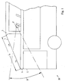
- FIG. 1 schematically shows a vehicle which has an upper glass pane 1 and a driver's pane 2.
- the disk 1 is inclined very flat to the horizontal, wherein it has a disk length L.
- the disc 1 has a front portion 1a and a rear portion 1b.
- the front area 1a lies in the field of view ⁇ of the passenger F, which can detect this from his eye point.
- the disk 1 is surrounded on the one hand by the vehicle roof 3 and on the other by the front body frame 4.
- the disc 1 has a front surface through which the passenger can look at the road ahead of the vehicle.
- the disc 1 is also formed so that it also has two side surfaces in addition to the front surface.
- the passenger can also view the area of the road adjacent to the left and right sides.
- FIG. 2 shows an embodiment of the device according to the invention.
- the device has a support arm 5, which is arranged in the vehicle interior and attached to its proximal end 6 on the vehicle roof 3.
- the support arm 5 protrudes without further support and thus cantilevered in the direction of the front portion 1a of the disc 1.
- an axis of rotation 8 is mounted, to which the windshield wiper 9 is mounted.
- the axis of rotation 8 penetrates the disc to be wiped 1 through a recess 10 through the disc 1. Since the support arm 5 is cantilevered, it does not support in the region of the recess 10 of the disc 1 from. Thus, the disc 1 is not burdened by the wiper arm induced forces and moments.
- the force and moment absorption takes place exclusively in the transition region of the proximal end 6 with the vehicle roof 3.
- the drive linkage 17 shown in FIG. 2 and the drive motor 18 for the windscreen wiper 9 can preferably be arranged such that it is located in the region of the support arm 5. This allows a low height can be achieved.
- the length of the support arm 5 may be designed so that with the windshield wiper 9, the entire front portion 1a of the disc 1 can wipe.
- the length of the support arm 5 is basically arbitrary, so that the position of the recess 10 in the glass pane 1 results from the length of the support arm 5 and the length of the windshield wiper 9.
- the support arm 5 can be covered with a cover 19 together with the drive linkage 17 and the drive motor 18. Preferably, this cover is no longer in the direct field of view ⁇ of the passenger F.
- this cover itself can be covered by a monitor which is connected to the cover.
- the monitor 20 e.g. a flat screen, is oriented with its display side towards the passenger interior.
- the monitor can be used to display safety advices or a television picture for entertainment to the passengers.
- FIG. 3 shows a detail of the device according to the invention.
- the axis of rotation 8 passes through the recess 10 of the glass pane 1, wherein the axis of rotation 8 is oriented perpendicular to the glass pane 1.
- an intermediate disc 12 is arranged, which is provided in its outer edge region with a sealing element 11.
- this sealing element 11 is an adhesive which fixes the position of the intermediate disc 12 with the glass pane 1 and at the same time assumes a damping function. Vibrations of the vehicle are thus not transmitted directly from the glass pane 1 on the washer 12.
- the washer 12 has a collar, on whose front side two seals are provided.
- a labyrinth seal 15 and an axial seal 14 are provided. Both seals are housed in a sealing flange 13, wherein the sealing flange 13 is fixedly connected to the axis of rotation 8.
- the sealing flange 13, the axial seal 14 and the labyrinth seal 15 thus move, the seals engaging the intermediate disk 12 on the front side of the collar.
- the sealing flange surrounds the intermediate disc collar, whereby penetration of liquid up to the seals is difficult.
- the labyrinth seal is designed axially in this embodiment.
- the labyrinth seal is a non-contact seal in which the sealing material engages in a gap which is incorporated in the collar of the intermediate disc. With a rotation of the axis of rotation occurs with correct adjustment of the labyrinth seal to no wear of the seal, whereby a high reliability in the sealing effect is achieved.
- the axial seal is oriented closer to the axis of rotation and rubbing touches the collar of the protective cover 12. This sealing system reliably prevents the ingress of dirt or moisture into the storage area of the device and thus into the interior of the vehicle.
- the receptacle for the windshield wiper 9 is attached.
- FIG. 4 shows a further embodiment of the invention.
- a conduit 16 is mounted, which can pass through the recess of the glass sheet 1 through a window cleaning liquid to the outside on the disk. For an effective cleaning of the disc 1 in cooperation with the windshield wiper 9 can be achieved.
- the conduit 16 is mounted with the washer 12 in this embodiment.
Abstract
Description
Die Erfindung betrifft eine Vorrichtung zur Lagerung eines Scheibenwischers eines Fahrzeuges und insbesondere eine Vorrichtung zur Lagerung eines Scheibenwischers eines Fahrzeuges, welche einen Tragarm aufweist, der am proximalen Ende am Fahrzeugdach angebracht ist und am distalen Ende freitragend eine Drehachse des Scheibenwischers aufweist, wobei die Drehachse die zu wischende Scheibe durch eine Aussparung durch die Scheibe durchdringt.The invention relates to a device for mounting a windshield wiper of a vehicle, and more particularly to a device for supporting a windshield wiper of a vehicle, which has a support arm which is attached to the vehicle roof at the proximal end and at the distal end cantilevered has an axis of rotation of the windshield wiper, wherein the axis of rotation to be wiped disc penetrates through a recess through the disc.
Bei einem Fahrzeug wie z.B. einem Omnibus kann im Dachbereich eine sehr flach geneigte Scheibe vorgesehen sein, welche eine Scheibenlänge von ca. 2 m aufweist. Ist eine derartige Scheibe mit einem Wischerarm zu reinigen, so sind mehrere Probleme zu lösen. Übliche Wischerarmlängen betragen etwa 1 m, so dass bei einer Montage des Wischerarms im Bereich des oberen Scheibenrandes oder des unteren Scheibenrandes eine Scheibe mit der genannten Länge von etwa 2 m nicht vollständig gereinigt werden kann. Wird ein Wischerarm im Bereich des Fahrzeugdaches 3 gelagert, siehe Figur 1, so müsste er eine Wischerarmlänge aufweisen, welche etwa die Länge L der Scheibenlänge beträgt. Ein Wischerarm mit einer solchen Länge ist jedoch üblicherweise nicht verfügbar. Wird der Wischerarm mit einer üblichen Länge von ca. 1 m im Bereich des vorderen Karosserierahmens 4 zwischen Scheibe 1 und Fahrerscheibe 2 gelagert, so dass der Wischerarm den vorderen Bereich 1a der Scheibe 1 wischen kann (Wischerarmspitze ist gegen Fahrrichtung gerichtet), so wird der hintere Bereich 1b der Scheibe 1 nicht erreicht. Dieser Nachteil mag jedoch von geringer Bedeutung sein, da das Sichtfeld ϕ eines Fahrgastes F von seinem Augenpunkt aus gesehen den hinteren Bereich 1b der Fahrzeugscheibe 1 nicht mehr erfasst. Wird ein Scheibenwischerarm zwischen der Scheibe 1 und der Fahrerscheibe 2 am Karosserierahmen 4 befestigt, kann somit der für das Sichtfeld ϕ relevante Anteil 1a der Scheibe 1 gereinigt und gewischt werden. Problematisch hierbei ist jedoch, dass die Lagervorrichtung des Scheibenwischers einschließlich Antriebsmotor und Antriebsgestänge in den Fahrgastraum hineinragt. Diese Baugruppen können zwar mit einer Abdeckung abgedeckt werden, liegen jedoch genau im Sichtfeld ϕ des Fahrgastes 5. Aus optischen Gründen wird dies als nachteilig bewertet.In a vehicle such as a bus can be provided in the roof area a very flat inclined disc, which has a disc length of about 2 m. If such a disc with a wiper arm to clean, so are several problems to solve. Usual Wischerarmlängen be about 1 m, so that when mounting the wiper arm in the region of the upper edge of the disc or the lower edge of the disc a disc with said length of about 2 m can not be completely cleaned. If a wiper arm is mounted in the region of the
Vor diesem Hintergrund liegt der Erfindung die Aufgabe zugrunde, eine Vorrichtung zur Lagerung eins Scheibenwischers zu schaffen, so dass bei sehr flach geneigter Scheibe der vordere Scheibenbereich mit dem Scheibenwischer gewischt werden kann, wobei im Sichtfeld der Fahrgäste möglichst wenig von einer zum Scheibenwischer zugehörigen Antriebsbaugruppe mit Antriebsmotor und Antriebsgestänge sichtbar ist.Against this background, the invention has the object to provide a device for storing a windshield wiper, so that at very flat inclined disc of the front disc area can be wiped with the windshield wiper, in the field of view of the passengers as little as possible by a windshield wiper associated drive assembly Drive motor and drive linkage is visible.
Die Lösung dieser Aufgabe ergibt sich aus den Merkmalen des Hauptanspruchs, während vorteilhafte Ausgestaltungen und Weiterbildungen der Erfindung den Unteransprüchen entnehmbar sind.The solution of this problem arises from the features of the main claim, while advantageous embodiments and further developments of the invention are the dependent claims can be removed.
Die erfindungsgemäße Vorrichtung zur Lagerung eines Scheibenwischers für ein Fahrzeug weist einen Tragarm auf, welcher an seinem proximalen Ende am Fahrzeugdach angebracht ist, am distalen Ende freitragend ist und am distalen Ende eine Drehachse aufweist, an welcher ein Scheibenwischer montiert ist. Dadurch ist es möglich, den vorderen Scheibenbereich mit dem Scheibenwischer zu reinigen, wobei der Tragarm die Distanz zwischen Fahrzeugdach und Drehachse des Scheibenwischers überbrückt. Die erforderlichen Baugruppen wie Antriebsgestänge und Antriebsmotor lassen sich in einer Zone nahe beim Tragarm oder im Tragarm montieren, wobei diese Zone im hinteren Bereich der Scheibe liegt. Somit ergibt sich keine Behinderung des Sichtfeldes für einen Fahrgast. Weil der Tragarm am Fahrzeugdach montiert und an seinem distalen Ende freitragend ist, wird die Glasscheibe im Bereich der Aussparung nicht belastet. Damit besteht keine Gefahr, dass wegen zu starker Kräfte und Momente (z.B. bei Schneelast) der Bereich um die Aussparung der Scheibe zu stark belastet wird und ein Bruch der Scheibe die Folge wäre.The inventive device for supporting a windshield wiper for a vehicle has a support arm, which is attached at its proximal end to the vehicle roof, cantilevered at the distal end and at the distal end has an axis of rotation on which a windshield wiper is mounted. This makes it possible to clean the front disc area with the windshield wiper, wherein the support arm bridges the distance between the vehicle roof and the axis of rotation of the windshield wiper. The required assemblies such as drive linkage and drive motor can be mounted in a zone near the support arm or in the support arm, which zone is located in the rear of the disc. Thus, there is no obstruction of the field of view for a passenger. Because the support arm is mounted on the vehicle roof and cantilevered at its distal end, the glass pane is not loaded in the region of the recess. There is therefore no risk that the area around the recess of the disk will be overstressed due to excessive forces and moments (for example under snow load) and a breakage of the disk would result.
Nach einer weiteren Ausführungsform durchdringt die Drehachse die zu wischende Scheibe durch eine Aussparung durch die Scheibe. Damit ist es möglich, die Drehachse vom Fahrzeuginnenraum aus anzutreiben.According to a further embodiment, the axis of rotation penetrates the disc to be wiped through a recess through the disc. This makes it possible to drive the axis of rotation from the vehicle interior.
Zudem kann bevorzugt vorgesehen sein, dass der Tragarm im Innenraum des Fahrzeuges angeordnet ist. Der Tragarm und die empfindlichen Bauelemente wie Gestänge und Antriebsmotor sind damit vor äußeren Witterungseinflüssen sicher geschützt.In addition, it can preferably be provided that the support arm is arranged in the interior of the vehicle. The support arm and the sensitive components such as linkage and drive motor are thus safely protected from external weather conditions.
Gemäß einer weiteren Ausführungsform kann die Aussparung durch die Glasscheibe in einem beliebigen Abstand vom Rand der Scheibe vorgesehen sein. Dies ist vorteilhaft, da somit das jeweilige Sichtfeld nicht beeinträchtigt wird und eine beliebige verfügbare Wischerlänge einsetzbar ist.According to a further embodiment, the recess may be provided through the glass sheet at any distance from the edge of the disk. This is advantageous because thus the respective field of view is not impaired and any available wiper length can be used.
Nach einer weiteren Ausführungsform ist die Drehachse mittels eines Dichtelementes mit der Glasscheibe verbunden. Dies ist vorteilhaft, da somit die Aussparung der Scheibe gegen von außen einwirkenden Schmutz oder Nässe abgedichtet ist.According to a further embodiment, the axis of rotation is connected by means of a sealing element with the glass pane. This is advantageous because thus the recess of the disc is sealed against external dirt or moisture.
Nach einer weiteren Ausführungsform ist zwischen Dichtelement und Drehachse eine Zwischenscheibe vorgesehen. Damit bleibt es freigestellt, ob das Dichtelement beweglich oder starr ausgebildet ist.According to a further embodiment, an intermediate disc is provided between the sealing element and the axis of rotation. This leaves it free, whether the sealing element is designed to be movable or rigid.
Nach einer weiteren Ausführungsform ist die Zwischenscheibe mit der Glasscheibe starr verbunden. Somit gibt es keine Bewegung auf der Glasoberfläche, welche eventuell uneben ist oder sich relativ rasch abnutzen kann.According to a further embodiment, the intermediate disc is rigidly connected to the glass sheet. Thus, there is no movement on the glass surface, which may be uneven or may wear out relatively quickly.
Nach einer weiteren Ausführungsform ist das Dichtelement Klebstoff. Der Klebstoff fixiert nicht nur die Zwischenscheibe mit der Glasscheibe, sondern übernimmt auch eine dämpfende Funktion.According to a further embodiment, the sealing element is adhesive. The adhesive not only fixes the washer with the glass, but also takes on a dampening function.
Nach einer weiteren Ausführungsform ist die Drehachse mittels eines Dichtungsflansches mit der Zwischenscheibe verbunden. Dies ermöglicht eine optimale Anpassung zwischen zwei zueinander abzudichtenden Teilen, wobei die Scheibe starr und der Flansch drehbar ausgebildet sein kann.According to a further embodiment, the axis of rotation is connected by means of a sealing flange with the intermediate disc. This allows an optimal adaptation between two parts to be sealed to each other, wherein the disc can be rigid and the flange can be rotatable.
Nach einer weiteren Ausführungsform ist zwischen Dichtungsflansch und Zwischenscheibe eine Axialdichtung vorgesehen. Dies ermöglicht eine wirksame Abdichtung gegenüber von außen einwirkender Nässe oder Schmutzpartikeln.According to a further embodiment, an axial seal is provided between the sealing flange and washer. This allows an effective seal against externally acting moisture or dirt particles.
Gemäß einer weiteren Ausführungsform kann zwischen Dichtungsflansch und Zwischenscheibe eine Labyrinthdichtung vorgesehen sein. Die Labyrinthdichtung ist eine berührungsfreie Schutzdichtung, wobei die Dichtfunktion durch eine Fluiddrosselung im Labyrinthspalt erreicht wird.According to a further embodiment, a labyrinth seal can be provided between the sealing flange and the intermediate disc. The labyrinth seal is a non-contact protective seal, whereby the sealing function is achieved by a fluid throttling in the labyrinth gap.
Nach einer weiteren Ausführungsform ist die Labyrinthdichtung der Axialdichtung vorgeschaltet. Von außen einwirkende Nässe muss somit zunächst die Labyrinthdichtung durchdringen, bevor sie die Axialdichtung erreicht. Bei dieser Ausführungsform wird somit eine sehr wirksame Abdichtung erzielt.According to a further embodiment, the labyrinth seal of the axial seal is connected upstream. Moisture acting from the outside must therefore first penetrate the labyrinth seal before it reaches the axial seal. In this embodiment, thus a very effective seal is achieved.
Nach einer weiteren Ausführungsform ist durch die Aussparung der Glasscheibe eine Leitung für die Scheibenreinigungsflüssigkeit nach außen durchführbar. Im Zusammenwirken mit dem Scheibenwischer lässt sich somit eine effektive Scheibenreinigung erzielen.According to a further embodiment, a line for the window cleaning liquid is carried out through the recess of the glass pane to the outside. In cooperation with the windscreen wiper can thus achieve an effective window cleaning.
Nach einer weiteren Ausführungsform ist die Drehachse mit einem Antriebsgestänge und einem Antriebsmotor verbunden, so dass die Drehachse antreibbar ist. Je nach Dimensionierung des Gestänges kann somit das Wischfeld variabel gestaltet werden.According to a further embodiment, the axis of rotation is connected to a drive linkage and a drive motor, so that the axis of rotation can be driven. Depending on the dimensions of the linkage thus the wiping field can be made variable.
Gemäß einer weiteren Ausführungsform ist die Vorrichtung zum Fahrgastinnenraum mittels einer Abdeckung abgedeckt. Damit wird ein Sichtschutz und ein Berührschutz für die Fahrgäste erreicht.According to a further embodiment, the device is covered to the passenger compartment by means of a cover. Thus, a privacy and protection against contact for the passengers is achieved.
Gemäß einer weiteren Ausführungsform ist ein Monitor mit der Abdeckung der erfindungsgemäßen Vorrichtung verbunden. Der Monitor kann somit in einem genügenden Abstand vom Fahrgast angeordnet werden, so dass auch in der ersten Sitzreihe die Anzeige des Monitors vom Fahrgast gut eingesehen werden kann. Würde der Monitor im Bereich des Fahrzeugdaches montiert, wäre der Abstand zwischen Fahrgast und Monitor zu kurz.According to a further embodiment, a monitor is connected to the cover of the device according to the invention. The monitor can thus be arranged at a sufficient distance from the passenger, so that the display of the monitor can be well viewed by the passenger in the first row of seats. If the monitor were mounted in the area of the vehicle roof, the distance between the passenger and the monitor would be too short.
Gemäß einer weiteren Ausführungsform ist das Fahrzeug, welches die Vorrichtung zur Lagerung eines Scheibenwischers aufweist, ein Omnibus. Damit ist die Vorrichtung für eine Panoramascheibe einsetzbar.According to a further embodiment, the vehicle having the device for mounting a windshield wiper is a bus. Thus, the device can be used for a panoramic window.
Im Folgenden wird die Erfindung anhand bevorzugter Ausführungsformen mit Bezugnahme auf die Zeichnung erläutert. In der Zeichnung zeigen:
Figur 1 eine schematische Darstellung eines Fahrzeuges mit einer Scheibe und dem Sichtfeld eines Fahrgastes,Figur 2 eine schematische Darstellung gemäß einer Ausführungsform der Erfindung,Figur 3 eine schematische Querschnittsdarstellung im Bereich der Drehachse der Vorrichtung gemäß einer Ausführungsform der Erfindung,Figur 4 eine schematische Darstellung einer weiteren Ausführungsform der erfindungsgemäßen Vorrichtung im Bereich der Drehachse des Scheibenwischers.
- 1 shows a schematic representation of a vehicle with a pane and the field of view of a passenger,
- FIG. 2 shows a schematic illustration according to an embodiment of the invention,
- FIG. 3 shows a schematic cross-sectional view in the region of the axis of rotation of the device according to an embodiment of the invention,
- Figure 4 is a schematic representation of another embodiment of the device according to the invention in the region of the axis of rotation of the windshield wiper.
In den Figuren sind für gleiche Teile gleiche Bezugszeichen verwendet.In the figures, like reference numerals are used for like parts.
In Figur 1 ist schematisch ein Fahrzeug dargestellt, welches eine obere Glasscheibe 1 und eine Fahrerscheibe 2 aufweist. Die Scheibe 1 ist sehr flach zur Horizontalen geneigt, wobei sie eine Scheibenlänge L aufweist. Die Scheibe 1 weist einen vorderen Bereich 1a und einen hinteren Bereich 1b auf. Der vordere Bereich 1a liegt im Sichtfeld ϕ des Fahrgastes F, welches dieser von seinem Augenpunkt aus erfassen kann. Die Scheibe 1 ist zum einen vom Fahrzeugdach 3 und zum anderen vom vorderen Karosserierahmen 4 umgeben. Die Scheibe 1 weist eine Frontfläche auf, durch welche der Fahrgast auf die vor dem Fahrzeug sich befindende Straße blicken kann. Vorzugsweise ist die Scheibe 1 auch so ausgebildet, dass sie neben der Frontfläche auch zwei Seitenflächen aufweist. Somit kann der Fahrgast auch den zur linken und rechten Seite benachbarten Bereich der Straße einsehen.FIG. 1 schematically shows a vehicle which has an
Eine Scheibenreinigung ist vorzugsweise im Bereich 1a erforderlich. Dies wird mit einem Scheibenwischer erzielt, welcher gemäß der Erfindung gelagert ist. In Figur 2 ist eine Ausführungsform der erfindungsgemäßen Vorrichtung dargestellt. Die Vorrichtung weist einen Tragarm 5 auf, welcher im Fahrzeuginnenraum angeordnet und an seinem proximalen Ende 6 am Fahrzeugdach 3 angebracht ist. Der Tragarm 5 ragt ohne weitere Stütze und somit freitragend in die Richtung zum vorderen Bereich 1a der Scheibe 1. An seinem distalen Ende 7 ist eine Drehachse 8 angebracht, an welche der Scheibenwischer 9 montiert ist. Die Drehachse 8 durchdringt die zu wischende Scheibe 1 durch eine Aussparung 10 durch die Scheibe 1. Da der Tragarm 5 freitragend ist, stützt er sich nicht im Bereich der Aussparung 10 der Scheibe 1 ab. Damit wird die Scheibe 1 durch vom Wischarm induzierte Kräfte und Momente nicht belastet. Die Kraft- und Momentenaufnahme geschieht ausschließlich im Übergangsbereich des proximalen Endes 6 mit dem Fahrzeugdach 3.A window cleaning is preferably required in the area 1a. This is achieved with a windshield wiper which is mounted according to the invention. FIG. 2 shows an embodiment of the device according to the invention. The device has a
Das in Figur 2 dargestellte Antriebsgestänge 17 und der Antriebsmotor 18 für den Scheibenwischer 9 kann vorzugsweise derart angeordnet sein, dass es sich im Bereich des Tragarmes 5 befindet. Damit kann eine geringe Bauhöhe erzielt werden. Die Länge des Tragarmes 5 kann so gestaltet sein, dass mit dem Scheibenwischer 9 der gesamte vordere Bereich 1a der Scheibe 1 wischen kann. Die Länge des Tragarms 5 ist grundsätzlich beliebig, so dass sich die Position der Aussparung 10 in der Glasscheibe 1 aus der Länge des Tragarmes 5 und der Länge des Scheibenwischers 9 ergibt. Der Tragarm 5 kann zusammen mit dem Antriebsgestänge 17 und dem Antriebsmotor 18 mit einer Abdeckung 19 abgedeckt werden. Vorzugsweise befindet sich diese Abdeckung nicht mehr im direkten Sichtfeld ϕ des Fahrgastes F. Bei einer besonderen Ausführungsform kann diese Abdeckung selbst durch einen Monitor abgedeckt werden, welcher mit der Abdeckung verbunden ist. Der Monitor 20, z.B. ein Flachbildschirm, ist mit seiner Anzeigeseite in Richtung zum Fahrgastinnenraum orientiert. Der Monitor kann dazu verwendet werden, um den Fahrgästen Sicherheitshinweise oder ein Fernsehbild zur Unterhaltung anzuzeigen.The
In Figur 3 ist ein Detail der erfindungsgemäßen Vorrichtung dargestellt. Die Drehachse 8 passiert die Aussparung 10 der Glasscheibe 1, wobei die Drehachse 8 senkrecht zur Glasscheibe 1 orientiert ist. Oberhalb der Glasscheibe 1 ist eine Zwischenscheibe 12 angeordnet, welche in ihrem äußeren Randbereich mit einem Dichtelement 11 versehen ist. Vorzugsweise ist dieses Dichtelement 11 ein Klebstoff, welcher die Position der Zwischenscheibe 12 mit der Glasscheibe 1 fixiert und gleichzeitig eine Dämpfungsfunktion übernimmt. Erschütterungen des Fahrzeugs werden somit nicht direkt von der Glasscheibe 1 auf die Zwischenscheibe 12 übertragen.FIG. 3 shows a detail of the device according to the invention. The axis of
Die Zwischenscheibe 12 weist einen Bund auf, an dessen Stirnseite zwei Dichtungen vorgesehen sind. Gemäß der in Figur 3 dargestellten Ausführungsformen ist eine Labyrinthdichtung 15 und eine Axialdichtung 14 vorgesehen. Beide Dichtungen sind in einem Dichtungsflansch 13 untergebracht, wobei der Dichtungsflansch 13 mit der Drehachse 8 fest verbunden ist. Bei ein rotierenden Drehachse 8 bewegen sich somit der Dichtungsflansch 13, die Axialdichtung 14 und die Labyrinthdichtung 15, wobei die Dichtungen an der Stirnseite des Bundes der Zwischenscheibe 12 angreifen. Vorzugsweise umgreift der Dichtungsflansch den Zwischenscheibenbund, wodurch ein Eindringen von Flüssigkeit bis zu den Dichtungen erschwert wird.The
Die Labyrinthdichtung ist in dieser Ausführungsform axial ausgeführt. Bei der Labyrinthdichtung handelt es sich um eine berührungsfreie Dichtung, bei der das Dichtmaterial in einen Spalt eingreift, welcher im Bund der Zwischenscheibe eingearbeitet ist. Bei einer Rotation der Drehachse kommt es bei korrekter Justage der Labyrinthdichtung zu keinem Verschleiß der Dichtung, wodurch eine hohe Zuverlässigkeit in der Dichtwirkung erreicht wird. Die Axialdichtung ist näher zur Drehachse orientiert und berührt schleifend den Bund der Schutzscheibe 12. Dieses Dichtsystem verhindert zuverlässig das Eindringen von Schmutz oder Nässe in den Lagerbereich der Vorrichtung und damit in den Innenraum des Fahrzeuges. Am Ende der Drehachse 8 ist die Aufnahme für den Scheibenwischer 9 angebracht.The labyrinth seal is designed axially in this embodiment. The labyrinth seal is a non-contact seal in which the sealing material engages in a gap which is incorporated in the collar of the intermediate disc. With a rotation of the axis of rotation occurs with correct adjustment of the labyrinth seal to no wear of the seal, whereby a high reliability in the sealing effect is achieved. The axial seal is oriented closer to the axis of rotation and rubbing touches the collar of the
In Figur 4 ist eine weitere Ausführungsform der Erfindung dargestellt. Zusätzlich zur Drehachse, dem Dichtungssystem und der Glasscheibe ist eine Leitung 16 angebracht, welche durch die Aussparung der Glasscheibe 1 hindurch eine Scheibenreinigungsflüssigkeit nach außen auf die Scheibe führen kann. Damit ist eine wirksame Reinigung der Scheibe 1 im Zusammenwirken mit dem Scheibenwischer 9 erreichbar. Die Leitung 16 ist bei dieser Ausfiihrungsform mit der Zwischenscheibe 12 montiert.FIG. 4 shows a further embodiment of the invention. In addition to the axis of rotation, the sealing system and the glass sheet, a conduit 16 is mounted, which can pass through the recess of the
- 11
- Glasscheibepane
- 1a1a
- vorderer Bereich der Glasscheibefront area of the glass pane
- 1b1b
- hinterer Bereich der GlasscheibeRear area of the glass pane
- 22
- Fahrerscheibedriver disc
- 33
- Fahrzeugdachvehicle roof
- 44
- vorderer Karosserierahmenfront body frame
- 55
- TragarmBeam
- 66
- proximales Ende des Tragarmesproximal end of the support arm
- 77
- distales Ende des Tragarmesdistal end of the support arm
- 88th
- Drehachseaxis of rotation
- 99
- Scheibenwischerwindshield wipers
- 1010
- Aussparung der GlasscheibeRecess of the glass pane
- 1111
- Dichtelementsealing element
- 1212
- Zwischenscheibewasher
- 1313
- Dichtungsflanschsealing flange
- 1414
- Axialdichtungaxial seal
- 1515
- Labyrinthdichtunglabyrinth seal
- 1616
- Leitung für ScheibenreinigungsflüssigkeitLine for window cleaning fluid
- 1717
- Antriebsgestängedrive linkage
- 1818
- Antriebsmotordrive motor
- 1919
- Abdeckungcover
- 2020
- Monitormonitor
- 3030
- Fahrzeugvehicle
- FF
- Fahrgastpassenger
- L'L '
-
Länge der Scheibe 1Length of the
disc 1 - aa
- freie Tragarmlängefree support arm length
- ϕφ
- Sichtfeldfield of view
Claims (18)
Priority Applications (3)
| Application Number | Priority Date | Filing Date | Title |
|---|---|---|---|
| EP04022356A EP1772332B1 (en) | 2004-09-20 | 2004-09-20 | Arrangement of a wiper on the vehicle |
| PL04022356T PL1772332T3 (en) | 2004-09-20 | 2004-09-20 | Arrangement of a wiper on the vehicle |
| CNB2005100076444A CN100542858C (en) | 2004-09-20 | 2005-02-07 | The bearing set of window glass wiper |
Applications Claiming Priority (1)
| Application Number | Priority Date | Filing Date | Title |
|---|---|---|---|
| EP04022356A EP1772332B1 (en) | 2004-09-20 | 2004-09-20 | Arrangement of a wiper on the vehicle |
Publications (2)
| Publication Number | Publication Date |
|---|---|
| EP1772332A1 true EP1772332A1 (en) | 2007-04-11 |
| EP1772332B1 EP1772332B1 (en) | 2012-08-08 |
Family
ID=34926622
Family Applications (1)
| Application Number | Title | Priority Date | Filing Date |
|---|---|---|---|
| EP04022356A Active EP1772332B1 (en) | 2004-09-20 | 2004-09-20 | Arrangement of a wiper on the vehicle |
Country Status (3)
| Country | Link |
|---|---|
| EP (1) | EP1772332B1 (en) |
| CN (1) | CN100542858C (en) |
| PL (1) | PL1772332T3 (en) |
Citations (6)
| Publication number | Priority date | Publication date | Assignee | Title |
|---|---|---|---|---|
| US2040966A (en) * | 1931-03-09 | 1936-05-19 | Murray Corp | Header construction for concealed windshield wipers |
| GB1448892A (en) * | 1974-04-29 | 1976-09-08 | Chrysler Uk | Vehicle window wipers |
| FR2673408A1 (en) * | 1991-03-01 | 1992-09-04 | Renault | Retractable window wiper device |
| JPH11198766A (en) * | 1998-01-19 | 1999-07-27 | Toyota Auto Body Co Ltd | Glass hatch opening and closing knob |
| JP2000203258A (en) * | 1999-01-13 | 2000-07-25 | Iseki & Co Ltd | Window hand of cabin |
| JP2004074940A (en) | 2002-08-20 | 2004-03-11 | Yanmar Agricult Equip Co Ltd | Vibration reducing device for tractor |
-
2004
- 2004-09-20 EP EP04022356A patent/EP1772332B1/en active Active
- 2004-09-20 PL PL04022356T patent/PL1772332T3/en unknown
-
2005
- 2005-02-07 CN CNB2005100076444A patent/CN100542858C/en active Active
Patent Citations (6)
| Publication number | Priority date | Publication date | Assignee | Title |
|---|---|---|---|---|
| US2040966A (en) * | 1931-03-09 | 1936-05-19 | Murray Corp | Header construction for concealed windshield wipers |
| GB1448892A (en) * | 1974-04-29 | 1976-09-08 | Chrysler Uk | Vehicle window wipers |
| FR2673408A1 (en) * | 1991-03-01 | 1992-09-04 | Renault | Retractable window wiper device |
| JPH11198766A (en) * | 1998-01-19 | 1999-07-27 | Toyota Auto Body Co Ltd | Glass hatch opening and closing knob |
| JP2000203258A (en) * | 1999-01-13 | 2000-07-25 | Iseki & Co Ltd | Window hand of cabin |
| JP2004074940A (en) | 2002-08-20 | 2004-03-11 | Yanmar Agricult Equip Co Ltd | Vibration reducing device for tractor |
Non-Patent Citations (3)
| Title |
|---|
| PATENT ABSTRACTS OF JAPAN vol. 1999, no. 12 29 October 1999 (1999-10-29) * |
| PATENT ABSTRACTS OF JAPAN vol. 2000, no. 10 17 November 2000 (2000-11-17) * |
| PATENT ABSTRACTS OF JAPAN vol. 2003, no. 12 5 December 2003 (2003-12-05) * |
Also Published As
| Publication number | Publication date |
|---|---|
| PL1772332T3 (en) | 2013-01-31 |
| EP1772332B1 (en) | 2012-08-08 |
| CN1751919A (en) | 2006-03-29 |
| CN100542858C (en) | 2009-09-23 |
Similar Documents
| Publication | Publication Date | Title |
|---|---|---|
| EP1945485B1 (en) | Wiper system for front windscreens of motor vehicles | |
| EP1529688A1 (en) | Kameraanordnung für Kraftfahrzeuge | |
| DE102008027430A1 (en) | Protection device for image recording unit of vehicle, has transparent disk arranged before image recording unit in moving manner, where cleaning device is formed from wash water-feeding unit, wash element and wiper element | |
| DE102008026056A1 (en) | Device for enlarging the field of view | |
| EP1714859A1 (en) | Compact auxiliary drive for a trailer | |
| DE102004059432B4 (en) | rearview mirror | |
| DE19628181A1 (en) | Bearing for an internal combustion engine | |
| DE3314456A1 (en) | Wiper device for motor vehicle windows | |
| DE102011119153A1 (en) | KARDANGELENKANORDNUNG AND A KARDANGELENK PROTECTION DEVICE | |
| EP1772332B1 (en) | Arrangement of a wiper on the vehicle | |
| DE4006708C2 (en) | Receptacle for bulletproof glass panes in a vehicle body | |
| DE3731922A1 (en) | WIPING DEVICE FOR WINDOWS OF MOTOR VEHICLES II | |
| DE3707233A1 (en) | Wiper system, in particular for wraparound windows of motor vehicles | |
| EP1238874A1 (en) | Window wiper | |
| DE602005000342T2 (en) | Device for covering and protecting the windscreen wiper blades of a motor vehicle in the inactive position | |
| DE19844017C2 (en) | windshield wipers | |
| DE10348444A1 (en) | Pivoting lid part for a vehicle comprises a lid edge that is provided with a protective profile having a flexible shear protection lip that rests in the non-deformed state in a common plane with the lid part | |
| EP1245466A1 (en) | Protective cover for wiper | |
| DE2001556C3 (en) | Windshield wiper assemblies for vehicles | |
| EP2076416A1 (en) | Wiper blade for cleaning a windscreen | |
| DE10259562A1 (en) | Wiper system for a vehicle | |
| DE19835697C2 (en) | Vehicle armor | |
| DE102004056676B4 (en) | Wiper system for vehicle windows | |
| DE2438752C3 (en) | Device window for driver's cabs, in particular of tractors, tractors and construction vehicles, arranged laterally below the windshield and in the direction of travel in front of the driver's cab door | |
| DE1995388U (en) | DEVICE FOR KEEPING MOTOR VEHICLE WINDOWS CLEAN. |
Legal Events
| Date | Code | Title | Description |
|---|---|---|---|
| PUAI | Public reference made under article 153(3) epc to a published international application that has entered the european phase |
Free format text: ORIGINAL CODE: 0009012 |
|
| AK | Designated contracting states |
Kind code of ref document: A1 Designated state(s): AT BE BG CH CY CZ DE DK EE ES FI FR GB GR HU IE IT LI LU MC NL PL PT RO SE SI SK TR |
|
| AX | Request for extension of the european patent |
Extension state: AL HR LT LV MK |
|
| 17P | Request for examination filed |
Effective date: 20070929 |
|
| 17Q | First examination report despatched |
Effective date: 20071109 |
|
| AKX | Designation fees paid |
Designated state(s): AT BE BG CH CY CZ DE DK EE ES FI FR GB GR HU IE IT LI LU MC NL PL PT RO SE SI SK TR |
|
| RAP1 | Party data changed (applicant data changed or rights of an application transferred) |
Owner name: MAN NUTZFAHRZEUGE AG |
|
| GRAP | Despatch of communication of intention to grant a patent |
Free format text: ORIGINAL CODE: EPIDOSNIGR1 |
|
| RTI1 | Title (correction) |
Free format text: ARRANGEMENT OF A WIPER ON THE VEHICLE |
|
| GRAS | Grant fee paid |
Free format text: ORIGINAL CODE: EPIDOSNIGR3 |
|
| GRAA | (expected) grant |
Free format text: ORIGINAL CODE: 0009210 |
|
| AK | Designated contracting states |
Kind code of ref document: B1 Designated state(s): AT BE BG CH CY CZ DE DK EE ES FI FR GB GR HU IE IT LI LU MC NL PL PT RO SE SI SK TR |
|
| RAP1 | Party data changed (applicant data changed or rights of an application transferred) |
Owner name: MAN TRUCK & BUS AG |
|
| REG | Reference to a national code |
Ref country code: GB Ref legal event code: FG4D Free format text: NOT ENGLISH |
|
| REG | Reference to a national code |
Ref country code: CH Ref legal event code: EP Ref country code: AT Ref legal event code: REF Ref document number: 569576 Country of ref document: AT Kind code of ref document: T Effective date: 20120815 |
|
| REG | Reference to a national code |
Ref country code: IE Ref legal event code: FG4D Free format text: LANGUAGE OF EP DOCUMENT: GERMAN |
|
| REG | Reference to a national code |
Ref country code: DE Ref legal event code: R096 Ref document number: 502004013669 Country of ref document: DE Effective date: 20121011 |
|
| REG | Reference to a national code |
Ref country code: NL Ref legal event code: T3 |
|
| REG | Reference to a national code |
Ref country code: SE Ref legal event code: TRGR |
|
| PG25 | Lapsed in a contracting state [announced via postgrant information from national office to epo] |
Ref country code: CY Free format text: LAPSE BECAUSE OF FAILURE TO SUBMIT A TRANSLATION OF THE DESCRIPTION OR TO PAY THE FEE WITHIN THE PRESCRIBED TIME-LIMIT Effective date: 20120808 Ref country code: FI Free format text: LAPSE BECAUSE OF FAILURE TO SUBMIT A TRANSLATION OF THE DESCRIPTION OR TO PAY THE FEE WITHIN THE PRESCRIBED TIME-LIMIT Effective date: 20120808 |
|
| REG | Reference to a national code |
Ref country code: PL Ref legal event code: T3 |
|
| PG25 | Lapsed in a contracting state [announced via postgrant information from national office to epo] |
Ref country code: GR Free format text: LAPSE BECAUSE OF FAILURE TO SUBMIT A TRANSLATION OF THE DESCRIPTION OR TO PAY THE FEE WITHIN THE PRESCRIBED TIME-LIMIT Effective date: 20121109 Ref country code: PT Free format text: LAPSE BECAUSE OF FAILURE TO SUBMIT A TRANSLATION OF THE DESCRIPTION OR TO PAY THE FEE WITHIN THE PRESCRIBED TIME-LIMIT Effective date: 20121210 Ref country code: SI Free format text: LAPSE BECAUSE OF FAILURE TO SUBMIT A TRANSLATION OF THE DESCRIPTION OR TO PAY THE FEE WITHIN THE PRESCRIBED TIME-LIMIT Effective date: 20120808 |
|
| BERE | Be: lapsed |
Owner name: MAN TRUCK & BUS A.G. Effective date: 20120930 |
|
| PG25 | Lapsed in a contracting state [announced via postgrant information from national office to epo] |
Ref country code: RO Free format text: LAPSE BECAUSE OF FAILURE TO SUBMIT A TRANSLATION OF THE DESCRIPTION OR TO PAY THE FEE WITHIN THE PRESCRIBED TIME-LIMIT Effective date: 20120808 Ref country code: CZ Free format text: LAPSE BECAUSE OF FAILURE TO SUBMIT A TRANSLATION OF THE DESCRIPTION OR TO PAY THE FEE WITHIN THE PRESCRIBED TIME-LIMIT Effective date: 20120808 Ref country code: ES Free format text: LAPSE BECAUSE OF FAILURE TO SUBMIT A TRANSLATION OF THE DESCRIPTION OR TO PAY THE FEE WITHIN THE PRESCRIBED TIME-LIMIT Effective date: 20121119 Ref country code: EE Free format text: LAPSE BECAUSE OF FAILURE TO SUBMIT A TRANSLATION OF THE DESCRIPTION OR TO PAY THE FEE WITHIN THE PRESCRIBED TIME-LIMIT Effective date: 20120808 Ref country code: MC Free format text: LAPSE BECAUSE OF NON-PAYMENT OF DUE FEES Effective date: 20120930 Ref country code: DK Free format text: LAPSE BECAUSE OF FAILURE TO SUBMIT A TRANSLATION OF THE DESCRIPTION OR TO PAY THE FEE WITHIN THE PRESCRIBED TIME-LIMIT Effective date: 20120808 |
|
| REG | Reference to a national code |
Ref country code: CH Ref legal event code: PL |
|
| PG25 | Lapsed in a contracting state [announced via postgrant information from national office to epo] |
Ref country code: SK Free format text: LAPSE BECAUSE OF FAILURE TO SUBMIT A TRANSLATION OF THE DESCRIPTION OR TO PAY THE FEE WITHIN THE PRESCRIBED TIME-LIMIT Effective date: 20120808 |
|
| PLBE | No opposition filed within time limit |
Free format text: ORIGINAL CODE: 0009261 |
|
| STAA | Information on the status of an ep patent application or granted ep patent |
Free format text: STATUS: NO OPPOSITION FILED WITHIN TIME LIMIT |
|
| REG | Reference to a national code |
Ref country code: IE Ref legal event code: MM4A |
|
| 26N | No opposition filed |
Effective date: 20130510 |
|
| GBPC | Gb: european patent ceased through non-payment of renewal fee |
Effective date: 20121108 |
|
| PG25 | Lapsed in a contracting state [announced via postgrant information from national office to epo] |
Ref country code: IE Free format text: LAPSE BECAUSE OF NON-PAYMENT OF DUE FEES Effective date: 20120920 Ref country code: BE Free format text: LAPSE BECAUSE OF NON-PAYMENT OF DUE FEES Effective date: 20120930 Ref country code: CH Free format text: LAPSE BECAUSE OF NON-PAYMENT OF DUE FEES Effective date: 20120930 Ref country code: BG Free format text: LAPSE BECAUSE OF FAILURE TO SUBMIT A TRANSLATION OF THE DESCRIPTION OR TO PAY THE FEE WITHIN THE PRESCRIBED TIME-LIMIT Effective date: 20121108 Ref country code: LI Free format text: LAPSE BECAUSE OF NON-PAYMENT OF DUE FEES Effective date: 20120930 |
|
| REG | Reference to a national code |
Ref country code: DE Ref legal event code: R097 Ref document number: 502004013669 Country of ref document: DE Effective date: 20130510 |
|
| REG | Reference to a national code |
Ref country code: AT Ref legal event code: MM01 Ref document number: 569576 Country of ref document: AT Kind code of ref document: T Effective date: 20120920 |
|
| REG | Reference to a national code |
Ref country code: HU Ref legal event code: AG4A Ref document number: E017178 Country of ref document: HU |
|
| PG25 | Lapsed in a contracting state [announced via postgrant information from national office to epo] |
Ref country code: GB Free format text: LAPSE BECAUSE OF NON-PAYMENT OF DUE FEES Effective date: 20121108 |
|
| PG25 | Lapsed in a contracting state [announced via postgrant information from national office to epo] |
Ref country code: AT Free format text: LAPSE BECAUSE OF NON-PAYMENT OF DUE FEES Effective date: 20120920 |
|
| PG25 | Lapsed in a contracting state [announced via postgrant information from national office to epo] |
Ref country code: LU Free format text: LAPSE BECAUSE OF NON-PAYMENT OF DUE FEES Effective date: 20120920 |
|
| REG | Reference to a national code |
Ref country code: FR Ref legal event code: PLFP Year of fee payment: 13 |
|
| REG | Reference to a national code |
Ref country code: FR Ref legal event code: PLFP Year of fee payment: 14 |
|
| REG | Reference to a national code |
Ref country code: FR Ref legal event code: PLFP Year of fee payment: 15 |
|
| REG | Reference to a national code |
Ref country code: DE Ref legal event code: R081 Ref document number: 502004013669 Country of ref document: DE Owner name: MAN TRUCK & BUS SE, DE Free format text: FORMER OWNER: MAN TRUCK & BUS AG, 80995 MUENCHEN, DE |
|
| PGFP | Annual fee paid to national office [announced via postgrant information from national office to epo] |
Ref country code: TR Payment date: 20230908 Year of fee payment: 20 Ref country code: NL Payment date: 20230926 Year of fee payment: 20 Ref country code: IT Payment date: 20230920 Year of fee payment: 20 |
|
| PGFP | Annual fee paid to national office [announced via postgrant information from national office to epo] |
Ref country code: SE Payment date: 20230926 Year of fee payment: 20 Ref country code: PL Payment date: 20230911 Year of fee payment: 20 Ref country code: HU Payment date: 20230908 Year of fee payment: 20 Ref country code: FR Payment date: 20230926 Year of fee payment: 20 Ref country code: DE Payment date: 20230928 Year of fee payment: 20 |