EP1945485B1 - Wiper system for front windscreens of motor vehicles - Google Patents
Wiper system for front windscreens of motor vehicles Download PDFInfo
- Publication number
- EP1945485B1 EP1945485B1 EP06807089A EP06807089A EP1945485B1 EP 1945485 B1 EP1945485 B1 EP 1945485B1 EP 06807089 A EP06807089 A EP 06807089A EP 06807089 A EP06807089 A EP 06807089A EP 1945485 B1 EP1945485 B1 EP 1945485B1
- Authority
- EP
- European Patent Office
- Prior art keywords
- wiper
- bearing
- axis
- fastening
- fastening part
- Prior art date
- Legal status (The legal status is an assumption and is not a legal conclusion. Google has not performed a legal analysis and makes no representation as to the accuracy of the status listed.)
- Expired - Fee Related
Links
Images

Classifications
-
- B—PERFORMING OPERATIONS; TRANSPORTING
- B60—VEHICLES IN GENERAL
- B60S—SERVICING, CLEANING, REPAIRING, SUPPORTING, LIFTING, OR MANOEUVRING OF VEHICLES, NOT OTHERWISE PROVIDED FOR
- B60S1/00—Cleaning of vehicles
- B60S1/02—Cleaning windscreens, windows or optical devices
- B60S1/04—Wipers or the like, e.g. scrapers
- B60S1/32—Wipers or the like, e.g. scrapers characterised by constructional features of wiper blade arms or blades
- B60S1/34—Wiper arms; Mountings therefor
- B60S1/3425—Constructional aspects of the arm
- B60S1/3445—Joints between elements
- B60S1/345—Joints between elements the elements being a link piece and a mounting head
-
- B—PERFORMING OPERATIONS; TRANSPORTING
- B60—VEHICLES IN GENERAL
- B60S—SERVICING, CLEANING, REPAIRING, SUPPORTING, LIFTING, OR MANOEUVRING OF VEHICLES, NOT OTHERWISE PROVIDED FOR
- B60S1/00—Cleaning of vehicles
- B60S1/02—Cleaning windscreens, windows or optical devices
- B60S1/04—Wipers or the like, e.g. scrapers
- B60S1/32—Wipers or the like, e.g. scrapers characterised by constructional features of wiper blade arms or blades
- B60S1/34—Wiper arms; Mountings therefor
- B60S1/3402—Wiper arms; Mountings therefor with means for obtaining particular wiping patterns
- B60S1/3409—Wiper arms; Mountings therefor with means for obtaining particular wiping patterns the wiper arms consisting of two or more articulated elements
-
- B—PERFORMING OPERATIONS; TRANSPORTING
- B60—VEHICLES IN GENERAL
- B60S—SERVICING, CLEANING, REPAIRING, SUPPORTING, LIFTING, OR MANOEUVRING OF VEHICLES, NOT OTHERWISE PROVIDED FOR
- B60S1/00—Cleaning of vehicles
- B60S1/02—Cleaning windscreens, windows or optical devices
- B60S1/04—Wipers or the like, e.g. scrapers
- B60S1/32—Wipers or the like, e.g. scrapers characterised by constructional features of wiper blade arms or blades
- B60S1/34—Wiper arms; Mountings therefor
- B60S1/3488—Means for mounting wiper arms onto the vehicle
- B60S1/3495—Means for mounting the drive mechanism to the wiper shaft
Definitions
- the invention relates to a wiper system for windscreens on motor vehicles.
- Wiper systems are used to maintain a clear view of a spontaneously occurring exposure of vehicle windows with the obstructive substances, especially in precipitation-related obstructions caused by adverse weather conditions.
- a movement of the wiper blade is often realized by a pivotable arm, which is connected via a hinge part with a fastening part which is pivoted about a fixed axis.
- the drive of the fastening part via a usually concealed installed wiper linkage, which transmits in conjunction with a wiper motor an alternating linear motion on a connected to the fastening part lever or a correspondingly designed bearing part.
- a pivotable fixing of the fastening part ensures an alternating pivoting movement of the fastening part, which transmits to the wiper arm.
- an elastic wiper blade is attached at the end of the pivotable wiper arm.
- the joint part is usually designed so that the pivotable arm is connected perpendicular to the pivoting plane of the fastening part deflectable with the fastening part and biased by spring force towards the front window, whereby the required contact pressure is generated on the wiper blade.
- the wiper blade can cover the largest possible area of the windshield, it is often desired to lay the swiveling axis as close as possible to or into the windshield. This requirement also partly results from the installation spaces available in vehicle construction, which make it expedient to place the wiper drive under the windshield.
- Such a windshield wiper device is known from EP-A-1 584 527 known.
- the object of the invention is to specify a possibility to have the largest possible surface area of a windscreen swept by a wiper system, without a carrying out a bearing shaft through the windscreen is required.
- the invention is based on a spatial separation of the pivot axis about which a wiper assembly is pivoted during cleaning of the windshield, of the bearing shaft, which serves to receive a mounting member which carries the wiper arm with the wiper blade.
- the pivot axis is determined in a conventional manner by a stationary shaft, a bearing pin or the like. On this pivot axis determining component, a pivotable bearing member is applied.
- this bearing part has a support structure which extends perpendicular to the pivot axis and which is designed to receive a fastening means, for example a bearing shaft.
- This fastening means serves to receive a fastening part, which is connected via a hinge part with a wiper arm.
- the aim is usually to arrange the wiper blade so that compression of the rubber lip is avoided during the removal.
- bidirectional wiper systems usually a corresponding folding of the lip of the wiper blade when changing direction, which is a largely vertical placement of the wiper blade on the disc requires. All these requirements can be met with the invention in an advantageous manner.
- Panoramic windows form in contrast to conventional windscreens a more curved boundary surface of the passenger compartment.
- the passenger compartment is surrounded in a larger solid angle range of the panoramic window, as is the case with conventional windscreens with low curvature.
- Panoramic slices therefore have, in contrast to conventional windscreens, either overall a greater curvature or surface areas with widely divergent radii of curvature.
- the use of panoramic windows is usually associated with a recessed A-pillar.
- the lateral edge areas of a panoramic window must also be included in the area covered by the wiper system. Even strongly curved lateral edge areas of a panorama window must at no time obstruct the driver's view. These specifications are covered by approval-relevant standards.
- a steeply standing wiper blade which is intended to cover the edge area of a panorama window, would be brought into contact with the window pane at a very unfavorable angle of attack by the orientation of this edge area which is changed compared to conventional windshields.
- This unfavorable angle of attack On the one hand, this would lead to a lower wiping performance and possibly increased wear of the wiper lip and, on the other hand, to very high frictional forces during the movement of the wiper blade, since the forces transmitted by the wiper linkage in the edge region of the panorama window will act to a considerable extent perpendicular to the swept surface and thus to one another additional pressing of the wiper blade would lead to the panoramic window.
- the angle at which the lip of the wiper blade is brought into contact with the window must be adapted to the respective surface area when passing over a panoramic window.
- the hinge axis deviates from the perpendicular to the main axis of the wiper arm at least in the plane in which the fastening part is pivoted.
- the deviation between the hinge axis of the hinge part and the perpendicular to the main axis of the wiper arm in the plane in which the fastening part is pivoted in the range between 5 ° and 45 °.
- An angle range between 5 ° and 30 ° has proven particularly useful.
- hinge part can be realized in various ways. It is important that it allows pivoting about a hinge axis and provides sufficient strength against attacking differently oriented moments.
- the joint part may comprise two eyes through which bearing bolts lead.
- the hinge part forms a separate component or is permanently connected to the wiper arm and / or the fastening part.
- the wiper blade can be moved between a steep end position in the strongly curved edge region of the panoramic window and a flat end position in the central, less curved region of the panoramic window.
- the pivot axis can be arranged so that only with a relatively steep wiper blade results in a significant change in the angle between the wiper arm and the fastening part.
- the wiper blade covers the relatively weakly curved central region of the panorama window with an almost constant angle of attack of the wiper lip.
- the orientation of the pivot axis about which the fastening part is pivoted and which is easily influenced by a bearing part according to the invention, and the angle by which the hinge axis of the joint part deviates from the orientation of the main axis of the wiper arm, represent parameters by their variation an adaptation of the wiper system according to the invention to different geometrical boundary conditions of different panoramic windows is possible.
- the forces required for maintaining the pivoting movement can also be optimized by varying the aforementioned parameters.
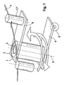
- FIG. 1 shows a schematic representation of a bearing part according to the invention 1.
- a bearing bushing 2 is pushed onto a bearing shaft 3, which is arranged stationarily below a run as a panoramic screen windscreen 4 in the vehicle interior.
- the bearing shaft 3 determines the position of the axis 5, around which the bearing part 1 can be pivoted.
- the bearing part 1 further comprises a fixedly connected to the bearing bush carrier 6, on which a bolt-shaped bearing shaft 7 is fixed at a fixed distance from the bearing bush 2 as a fastening means.
- This bearing shaft 7 serves to receive a fastening part, which can be connected at this point against rotation with the bearing part 1.
- the bearing bush 2 ensures a pivotable arrangement of the bearing part 1 on the bearing shaft. 3
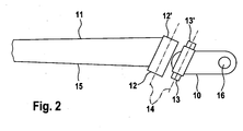
- FIG. 2 shows a representation of an advantageous hinge part, as it can be used together with a bearing part according to the invention in wiper systems on panoramic windows.
- the hinge part connects a fastening part 10 with a wiper arm 11 of a wiper system.
- the hinge part is formed hinge-shaped. Fixed to the wiper arm 11 are two cheeks 12, 12 'through the round openings lead. On the fastening part 10 bearing bolts 13, 13 'are mounted, which pass through the openings in the cheeks 12, 12'. In this way, a stable joint connection between the wiper arm 11 and the fastening part 10 is realized with a correspondingly strong design, which allows pivoting about exactly one hinge axis 14 and attacking differently oriented moments provides sufficient strength against.
- the joint part is not a separate component in the present embodiment, but is formed by a corresponding configuration of the mutually connectable ends of the wiper arm 11 and the fastening part 10.
- the illustration shows the joint part described in the separated state.
- the hinge axis 14 is inclined relative to the perpendicular to the main axis 15 of the wiper arm 11.
- an advantageous screwing in of the wiper blade during the intended pivotal movement of the fastening part 10 is enforced if an additional pivoting of the wiper arm 11 about the hinge axis 14 is associated with this pivoting movement.
- the fastening part 10 has at one end a fastening opening 16 into which the fastening means 7 engages on the bearing part 1 in order to connect the fastening part 10 to the bearing part 1 in a manner secured against rotation.
- FIG. 3 shows a schematic overall view of a wiper system according to the invention in different pivot states in front of a panoramic window 4 '.
- the arrangement consisting of wiper arm 11 with wiper blade, hinge part and fastening part 10 in approximately horizontal position, the wiper arm 11 covers the wiper blade in the present view, which is arranged so that the lip 17 of the wiper blade is approximately perpendicular to the panoramic plate 4 ' ,
- the wiper arm 11 forms an extension of the fastening part 10 and is connected thereto by an asymmetrical joint part with oblique joint axis 14.
- the fastening part 10 is pivotable about a fixed axis, which is determined by a bearing shaft 3, which ends hidden under the panoramic window.
- a bearing member 1 belonging to the invention fasteners in the form of a bolt-shaped bearing shaft 7 ', and allows a torsion-resistant, but adjustable connection of the fastening part 10 with the bearing part.
- fasteners in the form of a bolt-shaped bearing shaft 7 ', and allows a torsion-resistant, but adjustable connection of the fastening part 10 with the bearing part. 1 If the wiper assembly is pivoted in a steep position, the wiper arm 11 is erected and simultaneously pivoted out of the direction of extension of the fastening part 10 out. This pivoting takes place about the hinge axis 14, which is inclined relative to the main axis 15 of the wiper arm. The pivoting of the wiper arm 11 from the direction of extension of the fastening part 10 is therefore associated with a rotation of the wiper arm 11 about its major axis, which is illustrated by the appearance of the lip 17 of the wiper blade.
Description
Die Erfindung betrifft eine Wischeranlage für Frontscheiben an Kraftfahrzeugen.The invention relates to a wiper system for windscreens on motor vehicles.
Wischeranlagen dienen der Aufrechterhaltung einer freien Sicht bei einer spontan auftretenden Beaufschlagung von Fahrzeugscheiben mit die Sicht behindernden Substanzen, insbesondere bei niederschlagsbedingten Sichtbehinderungen durch widrige Witterungsbedingungen.Wiper systems are used to maintain a clear view of a spontaneously occurring exposure of vehicle windows with the obstructive substances, especially in precipitation-related obstructions caused by adverse weather conditions.
In modernen Kraftfahrzeugen finden sich zunehmend Frontscheiben mit gesteigerter Funktionalität. Das heißt, moderne Frontscheiben müssen neben der Gewährleistung einer ungehinderten Sicht des Fahrers weitere sicherheitsrelevante Funktionen vom mechanischen Insassenschutz bis hin zur statischen Einbeziehung in Festigkeitskalkulationen von Karosserie und Fahrgastraum erfüllen. Daraus folgen einerseits Veränderungen der Frontscheibengeometrie und Größe, andererseits Veränderungen des Frontscheibenmaterials, um den gesteigerten Sicherheits- und Festigkeitsanforderungen genügen zu können.In modern motor vehicles are increasingly windscreens with increased functionality. This means that modern windscreens must not only ensure unobstructed driver visibility, but also safety-related functions from mechanical occupant protection to static inclusion in structural and passenger compartment strength calculations. On the one hand, this results in changes to the windscreen geometry and size and, on the other, changes in the windscreen material in order to meet the increased safety and strength requirements.
Resultierend aus neuen Frontscheibenkonzepten ergeben sich teilweise erhöhte Anforderungen an einzusetzende Wischeranlagen. Ein vergrößertes Sichtfeld verändert die Sehgewohnheiten des Fahrers. Es dient zweifellos der Sicherheit, wenn diesen veränderten Sehgewohnheiten auch bei widrigen Witterungsbedingungen entsprochen wird, also die Frontscheibe möglichst vollständig von der Wischeranlage gereinigt werden kann, das heißt, die Wischer-Wischerblätter müssen unter gleichmäßigem Anpressdruck über möglichst große Flächenbereiche geführt werden.As a result of new windscreen concepts, there are sometimes increased requirements for wiper systems to be used. An enlarged field of vision changes the viewing habits of the driver. It is undoubtedly the safety, if these changed viewing habits are met even in adverse weather conditions, so the windshield can be cleaned as completely as possible from the wiper system, that is, the wiper blades must be guided under uniform contact pressure over the largest possible surface areas.
Eine Bewegung des Wischerblattes wird häufig durch einen schwenkbaren Arm realisiert, welcher über ein Gelenkteil mit einem Befestigungsteil verbunden ist, welches um eine feste Achse geschwenkt wird. Der Antrieb des Befestigungsteiles erfolgt über ein in der Regel verdeckt installiertes Wischergestänge, welches in Verbindung mit einem Wischermotor eine alternierende Linearbewegung auf einen mit dem Befestigungsteil verbundenen Hebel oder ein entsprechend ausgelegtes Lagerteil überträgt. Eine schwenkbewegliche Fixierung des Befestigungsteiles sorgt für eine alternierende Schwenkbewegung des Befestigungsteiles, die sich auf den Wischerarm überträgt. Am Ende des schwenkbaren Wischerarmes ist ein elastisches Wischerblatt angebracht. Damit das Wischerblatt der gekrümmten Fläche der Frontscheibe folgen kann, ist das Gelenkteil üblicherweise so konzipiert, dass der schwenkbare Arm senkrecht zur Schwenkebene des Befestigungsteiles auslenkbar mit dem Befestigungsteil verbunden und durch Federkraft in Richtung Frontscheibe vorgespannt ist, wodurch der erforderliche Anpressdruck am Wischerblatt erzeugt wird.A movement of the wiper blade is often realized by a pivotable arm, which is connected via a hinge part with a fastening part which is pivoted about a fixed axis. The drive of the fastening part via a usually concealed installed wiper linkage, which transmits in conjunction with a wiper motor an alternating linear motion on a connected to the fastening part lever or a correspondingly designed bearing part. A pivotable fixing of the fastening part ensures an alternating pivoting movement of the fastening part, which transmits to the wiper arm. At the end of the pivotable wiper arm an elastic wiper blade is attached. So that the wiper blade can follow the curved surface of the windshield, the joint part is usually designed so that the pivotable arm is connected perpendicular to the pivoting plane of the fastening part deflectable with the fastening part and biased by spring force towards the front window, whereby the required contact pressure is generated on the wiper blade.
Damit das Wischerblatt einen möglichst großen Flächenbereich der Frontscheibe überstreichen kann, wird häufig angestrebt, die Schwenkachse möglichst nah an oder in die Frontscheibe zu verlegen. Diese Forderung resultiert teilweise auch aus den im Fahrzeugbau zur Verfügung stehenden Einbauräumen, die eine Platzierung des Wischerantriebes unter der Frontscheibe zweckmäßig erscheinen lassen.So that the wiper blade can cover the largest possible area of the windshield, it is often desired to lay the swiveling axis as close as possible to or into the windshield. This requirement also partly results from the installation spaces available in vehicle construction, which make it expedient to place the wiper drive under the windshield.
Eine derartige Scheibenwischvorrichtung ist aus der
Es ist daher bekannt, eine die Schwenkachse der Wischeranlage bestimmende Lagerwelle, auf der ein den Wischerarm tragendes Befestigungsteil angebracht wird, durch eine Öffnung in der Frontscheibe zu führen. Diese Lösung hat jedoch den Nachteil, dass ein dafür erforderlicher Durchbruch der Frontscheibe bei vielen modernen Glasmaterialien, die für Frontscheiben eingesetzt werden, nicht mehr zulässig ist. Insbesondere bei häufig verwendeten Verbundgläsern ist eine derartige die Flächenstabilität und das Bruchverhalten beeinträchtigende Maßnahme unzulässig.It is therefore known to guide a bearing shaft which determines the pivot axis of the wiper system and on which a fastening part carrying the wiper arm is attached, through an opening in the windshield. However, this solution has the disadvantage that a required breakthrough of the windscreen in many modern glass materials, which are used for windscreens, is no longer allowed. In particular, in the case of frequently used laminated glass, such a measure which impairs the surface stability and the breaking behavior is inadmissible.
Die Aufgabe der Erfindung besteht darin, eine Möglichkeit anzugeben, einen möglichst großen Flächenbereich einer Frontscheibe von einer Wischeranlage überstreichen zu lassen, ohne dass eine Durchführung einer Lagerwelle durch die Frontscheibe erforderlich wird.The object of the invention is to specify a possibility to have the largest possible surface area of a windscreen swept by a wiper system, without a carrying out a bearing shaft through the windscreen is required.
Die Aufgabe wird erfüllt durch eine Wischeranlage mit den Merkmalen von Anspruch 1. Die abhängigen Ansprüche 2 bis 7 geben vorteilhafte Ausgestaltungen einer erfindungsgemäßen Wischeranlage an.The object is achieved by a wiper system with the features of
Die Erfindung beruht auf einer räumlichen Trennung der Schwenkachse, um welche eine Wischeranordnung während der Reinigung der Frontscheibe geschwenkt wird, von der Lagerwelle, die der Aufnahme eines Befestigungsteiles dient, das den Wischerarm mit dem Wischerblatt trägt. Die Schwenkachse wird in an sich bekannter Weise durch eine ortsfeste Welle, einen Lagerbolzen oder ähnliches festgelegt. Auf dieses die Schwenkachse bestimmende Bauteil wird ein schwenkbewegliches Lagerteil aufgebracht. Erfindungsgemäß weist dieses Lagerteil eine senkrecht zur Schwenkachse erstreckte Trägerstruktur auf, welche für die Aufnahme eines Befestigungsmittels, beispielsweise einer Lagerwelle, ausgelegt ist. Dieses Befestigungsmittel dient der Aufnahme eines Befestigungsteiles, das über ein Gelenkteil mit einem Wischerarm verbunden ist. Wird die Anordnung aus Wischerarm, Gelenkteil und Befestigungsteil verdrehsicher mit dem Befestigungsmittel an der Trägerstruktur des Lagerteiles verbunden, so bildet die Achse, um die das Lagerteil geschwenkt wird, gleichzeitig die Achse, um die die gesamte Wischeranordnung geschwenkt wird.The invention is based on a spatial separation of the pivot axis about which a wiper assembly is pivoted during cleaning of the windshield, of the bearing shaft, which serves to receive a mounting member which carries the wiper arm with the wiper blade. The pivot axis is determined in a conventional manner by a stationary shaft, a bearing pin or the like. On this pivot axis determining component, a pivotable bearing member is applied. According to the invention, this bearing part has a support structure which extends perpendicular to the pivot axis and which is designed to receive a fastening means, for example a bearing shaft. This fastening means serves to receive a fastening part, which is connected via a hinge part with a wiper arm. If the assembly of wiper arm, hinge part and fastening part is connected to the fastening structure on the support structure of the bearing part in a manner secured against rotation, then the axis about which the bearing part is pivoted simultaneously forms the axis about which the entire wiper arrangement is pivoted.
Durch die mit einer derartigen Anordnung verbundene räumliche Trennung der Schwenkachse, um welche die Wischeranordnung geschwenkt wird, von der Lagerwelle, die der Aufnahme des Befestigungsteiles dient, ist es möglich, die ortsfeste Welle, welche die Lage der Schwenkachse bestimmt, derart zu verkürzen, dass sie unter der Frontscheibe im Inneren eines Fahrzeuges angeordnet werden kann, ohne die Frontscheibe zu berühren. Eine Durchführung durch die Frontscheibe wird damit überflüssig. Die Erstreckung der Trägerstruktur wird so gewählt, dass die Lagerwelle für die Aufnahme des Befestigungsteiles unterhalb des Randes der Frontscheibe angeordnet wird und ausreichend Platz für eine Schwenkung des Lagerteiles bleibt, ohne dass es zu einer Berührung der Frontscheibe kommt.By the associated with such an arrangement spatial separation of the pivot axis about which the wiper assembly is pivoted, of the bearing shaft, which serves to receive the fastening part, it is possible to shorten the fixed shaft, which determines the position of the pivot axis, such that it can be placed under the windscreen inside a vehicle without touching the windscreen. A passage through the windscreen is thus superfluous. The extent of the support structure is chosen so that the bearing shaft for receiving the fastening part is arranged below the edge of the windshield and sufficient space for a pivoting of the bearing part remains, without causing a contact of the windscreen.
Herkömmliche Frontscheiben sind in der Regel relativ flach mit geringer Krümmung ausgeführt und weisen im gesamten von Wischerblättern zu überstreichenden Bereich geringe Krümmungsänderungen auf. Für einen Einsatz an derartigen Scheiben entsprechend ausgelegte Wischeranlagen führen mindestens ein Wischerblatt über die Scheibe, welches aus einer elastischen Halterung besteht, die ein bandförmiges Gummiprofil mit einer für ein Abziehen der Scheibe geeigneten Lippe aufnimmt. Die elastischen Eigenschaften des Wischerblattes erlauben den Ausgleich geringer Unterschiede zwischen der Krümmung der Scheibe und der Krümmung des Wischerblattes im entspannten Zustand. Dies sorgt neben einer optimierten Materialwahl und einer angepassten Lippenform am Wischerblatt in Zusammenhang mit einer entsprechenden Ausrichtung der aufgesetzten Lippe des Wischerblattes in Bezug auf die Normale der überstrichenen Zone der Scheibe für eine effektive und gleichmäßige Freihaltung der Frontscheibe von Spritz- und Niederschlagswasser. Insbesondere wird in der Regel angestrebt, das Wischerblatt so anzuordnen, dass während des Abziehens Stauchungen der Gummilippe vermieden werden. Bei bidirektional arbeitenden Wischeranlagen erfolgt meist ein entsprechendes Umklappen der Lippe des Wischerblattes beim Richtungswechsel, was ein weitgehend senkrechtes Aufsetzen des Wischerblattes auf der Scheibe erfordert. All diese Anforderungen lassen sich mit der Erfindung auf vorteilhafte Weise erfüllen.Conventional windshields are usually made relatively flat with little curvature and have in the entire area to be swept by wiper blades small changes in curvature. For use on such discs appropriately designed wiper systems lead at least one wiper blade on the disc, which consists of an elastic holder which receives a band-shaped rubber profile with a suitable for removing the disc lip. The elastic properties of the wiper blade allow the compensation of small differences between the curvature of the disc and the curvature of the wiper blade in the relaxed state. This provides, in addition to an optimized choice of material and an adapted lip shape on the wiper blade in conjunction with a corresponding orientation of the attached lip of the wiper blade with respect to the normal of the swept zone of the disc for an effective and uniform free attitude of the windshield of spray and rain water. In particular, the aim is usually to arrange the wiper blade so that compression of the rubber lip is avoided during the removal. In bidirectional wiper systems usually a corresponding folding of the lip of the wiper blade when changing direction, which is a largely vertical placement of the wiper blade on the disc requires. All these requirements can be met with the invention in an advantageous manner.
Für eine Verwendung der Erfindung an Panoramascheiben ist es jedoch möglicherweise nicht ausreichend, die Flächenerfüllung durch Verlagerung der Schwenkachse unter die Scheibe zu verbessern.However, for use of the invention on panoramic windows, it may not be sufficient to improve surface filling by displacing the pivot axis under the pane.
Panoramascheiben bilden im Gegensatz zu herkömmlichen Frontscheiben eine stärker gekrümmte Begrenzungsfläche des Fahrgastraumes. Der Fahrgastraum wird in einem größeren Raumwinkelbereich von der Panoramascheibe umgeben, als das bei herkömmlichen Frontscheiben mit geringer Krümmung der Fall ist. Panoramascheiben weisen daher im Gegensatz zu herkömmlichen Frontscheiben entweder insgesamt eine stärkere Krümmung oder Flächenbereiche mit stark voneinander abweichenden Krümmungsradien auf. Der Einsatz von Panoramascheiben.ist in der Regel mit einer zurückgesetzten A-Säule verbunden. Aus Sicherheitsgründen müssen auch die seitlichen Randbereiche einer Panoramascheibe in die von der Wischeranlage überstrichene Fläche mit einbezogen werden. Selbst stark gekrümmte seitliche Randbereiche einer Panoramascheibe dürfen zu keiner Zeit die Sicht des Fahrers behindern. Diese Vorgaben sind durch zulassungsrelevante Normen abgedeckt.Panoramic windows form in contrast to conventional windscreens a more curved boundary surface of the passenger compartment. The passenger compartment is surrounded in a larger solid angle range of the panoramic window, as is the case with conventional windscreens with low curvature. Panoramic slices therefore have, in contrast to conventional windscreens, either overall a greater curvature or surface areas with widely divergent radii of curvature. The use of panoramic windows is usually associated with a recessed A-pillar. For safety reasons, the lateral edge areas of a panoramic window must also be included in the area covered by the wiper system. Even strongly curved lateral edge areas of a panorama window must at no time obstruct the driver's view. These specifications are covered by approval-relevant standards.
Die gegenüber herkömmlichen Frontscheiben stärkere oder stark unterschiedliche Krümmung einer Panoramascheibe kann in keinem Fall durch die elastischen Eigenschaften des Wischerblattes ausgeglichen werden.The over conventional windshields stronger or greatly different curvature of a panoramic window can be compensated in any case by the elastic properties of the wiper blade.
Zudem würde ein steil stehendes Wischerblatt, weiches den Randbereich einer Panoramascheibe überstreichen soll, durch die gegenüber herkömmlichen Frontscheiben veränderte Orientierung dieses Randbereiches in einem sehr ungünstigen Angriffswinkel mit der Scheibe in Kontakt gebracht werden. Dieser ungünstige Angriffswinkel würde einerseits zu einer geringeren Wischleistung und einem evtl. erhöhten Verschleiß der Wischerlippe, andererseils zu sehr hohen Reibungskräften bei der Bewegung des Wischerblattes führen, da im Randbereich der Panoramascheibe die vom Wischergestänge übertragenen Kräfte zu einem erheblichen Teil senkrecht zur überstrichenen Fläche angreifen und damit zu einem zusätzlichen Anpressen des Wischerblattes an die Panoramascheibe führen würden. Da die Verbindung zwischen dem Wischergestänge und dem Befestigungsteil ohnehin den kurzen Hebel eines Systems darstellt, dessen langer Hebel durch den Wischerarm und das Wischerblatt gebildet wird, wären durch das Wischergestänge außerordentlich hohe Kräfte aufzubringen, um das Wischerblatt aus dem Randbereich der Panoramascheibe in den zentralen Bereich zurück zu schwenken. Bei üblicher Dimensionierung bestünde in Abhängigkeit vom Gleitverhalten der Wischerlippe auf der zu reinigenden Oberfläche zudem die Gefahr eines Blockierens des Wischers, was bei einer stark verschmutzten Frontscheibe zu einer akuten Gefährdung beteiligter Verkehrsteilnehmer führen würde. Die angesprochene Problematik wird durch bei hohen Geschwindigkeiten auftretende Windlasten noch verschärft.In addition, a steeply standing wiper blade, which is intended to cover the edge area of a panorama window, would be brought into contact with the window pane at a very unfavorable angle of attack by the orientation of this edge area which is changed compared to conventional windshields. This unfavorable angle of attack On the one hand, this would lead to a lower wiping performance and possibly increased wear of the wiper lip and, on the other hand, to very high frictional forces during the movement of the wiper blade, since the forces transmitted by the wiper linkage in the edge region of the panorama window will act to a considerable extent perpendicular to the swept surface and thus to one another additional pressing of the wiper blade would lead to the panoramic window. Since the connection between the wiper linkage and the fastening part anyway represents the short lever of a system whose long lever is formed by the wiper arm and the wiper blade, would be applied by the wiper linkage exceptionally high forces to the wiper blade from the edge region of the panoramic window in the central area to swing back. In the case of conventional dimensioning, depending on the sliding behavior of the wiper lip on the surface to be cleaned, there would also be the risk of blockage of the wiper, which would lead to an acute endangerment of road users involved in a severely contaminated windshield. The problem addressed is aggravated by occurring at high speeds wind loads.
Insbesondere der Winkel, in welchem die Lippe des Wischerblattes mit der Scheibe in Kontakt gebracht wird, muss beim Überstreichen einer Panoramascheibe somit an den jeweiligen Flächenbereich angepasst werden.In particular, the angle at which the lip of the wiper blade is brought into contact with the window must be adapted to the respective surface area when passing over a panoramic window.
Beim einem Einsatz einer erfindungsgemäßen Wischeranlage an Panoramascheiben ist es daher Vorteilhaft, zusätzlich zum erfindungsgemäßen Lagerteil zur Verbindung von Wischerarm und Befestigungsteil ein Gelenkteil zu verwenden, welches in Abhängigkeit vom Hubwinkel eine Normalenkorrektur des Wischerblattes realisiert.When using a wiper system according to the invention on panoramic windows, it is therefore advantageous to use a joint part in addition to the bearing part according to the invention for connecting wiper arm and fastening part, which realizes a normal correction of the wiper blade as a function of the stroke angle.
Dazu eignen sich beispielsweise Gelenkteile, die so ausgeführt sind, dass die Gelenkachse deutlich aus der Ebene senkrecht zur Hauptachse des Wischerarmes herausragt. Es hat sich gezeigt, dass in diesem Fall aerodynamische Vorteile mit dem Vorteil eines weitgehend senkrechten Aufsetzens der Lippe des Wischerblattes während des gesamten Wischvorganges auch vor Panoramascheiben kombiniert werden können. Ein derartiges Gelenkteil erzwingt eine Drehung des Wischerblattes um die Hauptachse des Wischerarmes, wenn sich der Winkel zwischen dem Wischerarm und dem Befestigungsteil ändert. Diese Drehung des Wischerblattes wird genutzt, um die Lippe des Wischerblattes stets annähernd senkrecht, zumindest jedoch ausreichend steil, über die Frontscheibe zu führen, auch wenn diese eine starke Krümmung aufweist.These are, for example, joint parts, which are designed so that the hinge axis clearly from the plane perpendicular to Main axis of the wiper arm protrudes. It has been shown that in this case aerodynamic advantages can be combined with the advantage of a largely vertical placement of the lip of the wiper blade during the entire wiping process even before panoramic slices. Such a hinge member forces rotation of the wiper blade about the main axis of the wiper arm as the angle between the wiper arm and the mounting member changes. This rotation of the wiper blade is used to guide the lip of the wiper blade always approximately perpendicular, but at least sufficiently steep, over the windshield, even if it has a strong curvature.
Vorteilhaft ist die Verwendung eines einachsigen Gelenkteiles, dessen Gelenkachse zumindest in der Ebene, in der das Befestigungsteil geschwenkt wird, von der Senkrechten zur Hauptachse des Wischerarmes abweicht.Advantageously, the use of a uniaxial joint part, the hinge axis deviates from the perpendicular to the main axis of the wiper arm at least in the plane in which the fastening part is pivoted.
Vorteilhafterweise liegt die Abweichung zwischen der Gelenkachse des Gelenkteiles und der Senkrechten zur Hauptachse des Wischerarmes in der Ebene, in der das Befestigungsteil geschwenkt wird, im Bereich zwischen 5° und 45°. Besonders bewährt hat sich ein Winkelbereich zwischen 5° und 30°.Advantageously, the deviation between the hinge axis of the hinge part and the perpendicular to the main axis of the wiper arm in the plane in which the fastening part is pivoted, in the range between 5 ° and 45 °. An angle range between 5 ° and 30 ° has proven particularly useful.
Ein in eine erfindungsgemäße Wischeranlage integriertes Gelenkteil lässt sich auf verschiedene Weise realisieren. Wichtig ist, dass es eine Schwenkung um eine Gelenkachse ermöglicht und angreifenden anders ausgerichteten Momenten eine ausreichende Festigkeit entgegen setzt. Beispielsweise kann das Gelenkteil zwei Augen umfassen, durch die Lagerbolzen führen. Für die Realisierung der Erfindung ist es unerheblich, ob das Gelenkteil ein separates Bauteil bildet oder unlösbar mit dem Wischerarm und/oder dem Befestigungsteil verbunden ist.An integrated in a wiper system according to the invention hinge part can be realized in various ways. It is important that it allows pivoting about a hinge axis and provides sufficient strength against attacking differently oriented moments. For example, the joint part may comprise two eyes through which bearing bolts lead. For the realization of the invention, it is irrelevant whether the hinge part forms a separate component or is permanently connected to the wiper arm and / or the fastening part.
Beim Einsatz einer erfindungsgemäßen Wischeranlage an Panoramascheiben mit schwach gekrümmten Zentralbereich und stark gekrümmten Randbereichen ist es besonders vorteilhaft, wenn das Wischerblatt zwischen einer steilen Endposition im stark gekrümmten Randbereich der Panoramascheibe und einer flachen Endposition im zentralen schwächer gekrümmten Bereich der Panoramascheibe bewegt werden kann. Bei derartigen Systemen mit außen liegender Lagerung kann die Schwenkachse so angeordnet werden, dass sich erst bei einem relativ steil stehenden Wischerblatt eine deutliche Änderung des Winkels zwischen dem Wischerarm und dem Befestigungsteil ergibt. Dadurch überstreicht das Wischerblatt den relativ schwach gekrümmten zentralen Bereich der Panoramascheibe mit nahezu konstantem Anstellwinkel der Wischerlippe. Erst bei steiler stehendem Wischerblatt erfolgt ein deutliches erfindungsgemäßes Eindrehen des Wischerblattes, was eine Anpassung der Bewegung an den stärker gekrümmten Randbereich der Panoramascheibe ermöglicht. Dadurch müssen keine starken Krümmungsunterschiede durch eine elastische Verformung des Wischerblattes ausgeglichen werden, und es kann krümmungsunabhängig ein gleichmäßiger Anpressdruck über die gesamte Länge des Wischerblattes realisiert werden.When using a wiper system according to the invention on panoramic windows with slightly curved central area and strongly curved Edge regions, it is particularly advantageous if the wiper blade can be moved between a steep end position in the strongly curved edge region of the panoramic window and a flat end position in the central, less curved region of the panoramic window. In such systems with external bearing, the pivot axis can be arranged so that only with a relatively steep wiper blade results in a significant change in the angle between the wiper arm and the fastening part. As a result, the wiper blade covers the relatively weakly curved central region of the panorama window with an almost constant angle of attack of the wiper lip. Only when the wiper blade is standing more steeply is the screwing-in of the wiper blade according to the invention significantly increased, which makes it possible to adapt the movement to the more curved edge region of the panoramic window. As a result, no strong curvature differences must be compensated by an elastic deformation of the wiper blade, and it can be independent of curvature, a uniform contact pressure over the entire length of the wiper blade realized.
Die Ausrichtung der Schwenkachse, um die das Befestigungsteil geschwenkt wird und die auf einfache Weise durch ein erfindungsgemäßes Lagerteil zu beeinflussen ist, und der Winkel, um den die Gelenkachse des Gelenkteiles von der Ausrichtung der Hauptachse des Wischerarmes abweicht, stellen Parameter dar, durch deren Variation eine Anpassung der erfindungsgemäßen Wischeranlage an unterschiedliche geometrische Randbedingungen unterschiedlicher Panoramascheiben möglich wird. Die für die Aufrechterhaltung der Schwenkbewegung erforderlichen Kräfte können durch Variation der vorgenannten Parameter ebenfalls optimiert werden.The orientation of the pivot axis about which the fastening part is pivoted and which is easily influenced by a bearing part according to the invention, and the angle by which the hinge axis of the joint part deviates from the orientation of the main axis of the wiper arm, represent parameters by their variation an adaptation of the wiper system according to the invention to different geometrical boundary conditions of different panoramic windows is possible. The forces required for maintaining the pivoting movement can also be optimized by varying the aforementioned parameters.
An einem Ausführungsbeispiel wird die Erfindung näher erläutert. Es zeigen:
- Fig. 1
- eine schematische Darstellung eines erfindungsgemäßen LagerLeiles,
- Fig. 2
- eine Darstellung eines vorteilhaften Gelenkteiles,
- Fig. 3
- eine schematische Gesamtdarstellung einer erfindungsgemäßen Wischeranlage in verschiedenen Schwenkzuständen.
- Fig. 1
- a schematic representation of a LagerLeiles invention,
- Fig. 2
- a representation of an advantageous hinge part,
- Fig. 3
- a schematic overall view of a wiper system according to the invention in different pivot states.
Auf diese Weise wird eine räumliche Trennung der Schwenkachse 5, um welche das Lagerteil, und damit die Wischeranordnung geschwenkt wird, von der Lagerwelle, die der Aufnahme des Befestigungsteiles dient, realisiert. Erst durch diese Trennung ist es möglich, die ortsfeste Welle 3, welche die Lage der Schwenkachse 5 bestimmt, derart zu verkürzen, dass sie unter der Frontscheibe 4 im Inneren eines Fahrzeuges angeordnet werden kann, ohne die Frontscheibe 4 zu berühren. Eine Durchführung durch die Frontscheibe wird damit überflüssig. Die Erstreckung des Trägers 6 wird so gewählt, dass die Lagerwelle 7 für die Aufnahme des Befestigungsteiles unterhalb des Randes der Frontscheibe 4 angeordnet wird und ausreichend Platz für eine Schwenkung des Lagerteiles 1 bleibt, ohne dass es zu einer Berührung der Frontscheibe 4 kommt. Die Pfeile verdeutlichen den Bewegungsablauf bei Betätigung der Wischeranlage. Im unteren Teil der Lagerbuchse 2 ist ein Hebel 8 angebracht, an dem das WischergesLänge angreift, was durch einen kugelförmigen Lagerkopf 9 symbolisiert wird.In this way, a spatial separation of the pivot axis 5 about which the bearing part, and thus the wiper assembly is pivoted, realized by the bearing shaft, which serves to receive the fastening part. Only by this separation, it is possible to shorten the stationary shaft 3, which determines the position of the pivot axis 5, such that it can be arranged under the windscreen 4 inside a vehicle without touching the windscreen 4. A passage through the windscreen is thus superfluous. The extent of the carrier 6 is chosen so that the bearing
Das Gelenkteil verbindet ein Befestigungsteil 10 mit einem Wischerarm 11 einer Wischeranlage. Das Gelenkteil ist scharnierförmig ausgebildet. Fest mit dem Wischerarm 11 verbunden sind zwei Wangen 12, 12' durch die runde Öffnungen führen. Am Befestigungsteil 10 sind Lagerbolzen 13, 13' angebracht, die durch die Öffnungen in den Wangen 12, 12' führen. Auf diese Weise wird bei entsprechend starker Auslegung eine stabile Gelenkverbindung zwischen dem Wischerarm 11 und dem Befestigungsteil 10 realisiert, die eine Schwenkung um genau eine Gelenkachse 14 ermöglicht und angreifenden anders ausgerichteten Momenten eine ausreichende Festigkeit entgegen setzt. Das Gelenkteil stellt im vorliegenden Ausführungsbeispiel kein separates Bauteil dar, sondern wird durch eine entsprechende Ausgestaltung der miteinander verbindbaren Enden des Wischerarmes 11 und des Befestigungsteiles 10 gebildet.The hinge part connects a
Die Darstellung zeigt das beschriebene Gelenkteil im getrennten Zustand. Die Gelenkachse 14 ist gegenüber der Senkrechten zur Hauptachse 15 des Wischerarmes 11 geneigt. Dadurch wird ein vorteilhaftes Eindrehen des Wischerblattes während der bestimmungsgemäßen Schwenkbewegung des Befestigungsteiles 10 erzwungen, wenn mit dieser Schwenkbewegung eine zusätzliche Schwenkung des Wischerarmes 11 um die Gelenkachse 14 verbunden ist. Das Befestigungsteil 10 weist an einem Ende eine Befestigungsöffnung 16 auf in die das Befestigungsmittel 7 am Lagerteil 1 eingreift, um das Befestigungsteil 10 verdrehsicher mit dem Lagerteil 1 zu verbinden.The illustration shows the joint part described in the separated state. The
Wird die Wischeranordnung in eine steile Position geschwenkt, wird der Wischerarm 11 aufgerichtet und gleichzeitig aus der Richtung der Verlängerung des Befestigungsteiles 10 heraus geschwenkt. Diese Schwenkung erfolgt um die Gelenkachse 14, die gegen die Hauptachse 15 des Wischerarmes geneigt ist. Das Ausschwenken des Wischerarmes 11 aus der Richtung der Verlängerung des Befestigungsteiles 10 ist deshalb mit einer Drehung des Wischerarmes 11 um seine Hauptachse verbunden, was durch die Sichtbarwerdung der Lippe 17 des Wischerblattes verdeutlicht wird. Auf diese Weise kann gesichert werden, dass die Lippe 17 des Wischerblattes auch im seitlichen Randbereich der Panoramascheibe 4', der gegenüber dem zentralen Bereich eine deutlich veränderte Orientierung aufweist, nahezu senkrecht oder zumindest ausreichend steil aufsetzt, um eine schonende und effektive Reinigungswirkung zu erzielen.
If the wiper assembly is pivoted in a steep position, the
Claims (7)
- Wiper system for front windscreens of motor vehicles, comprising at least one wiper blade which can be guided over the front windscreen (4) on a pivotable wiper arm (11), at least one bearing part (1) which is pivotable about an axis (5), at least one fastening part (10) which is connectable to said bearing part (1) in a manner secure against rotation, and at least one single-axis articulation part, which connects the wiper arm (11) to the fastening part (10), wherein the position of the connection of the bearing part (1) and fastening part (10) is located next to the axis (5) about which the bearing part (1) is pivoted, and the bearing part (1) comprises a bearing bushing (2) which is placed pivotable onto a positionally fixed bearing shaft (3), wherein the axis (5) runs through the front windscreen (4), wherein a support structure (6) which is connected to the bearing bushing (2) extends perpendicularly to the pivot axis (5) and is connected outside the pivot axis (5) to a fastening means (7), to which the fastening part (10) of the wiper arrangement can be fastened, characterized in that the fastening means (7) comprises a bolt-shaped bearing shaft (7'), the fastening part (10) has a fastening opening (16) into which the bolt-shaped bearing shaft (7') can be inserted, and means permitting a rotationally secure, but adjustable fastening of the fastening part (10) to the bolt-shaped bearing shaft (7') are included, wherein the positionally fixed bearing shaft (3) is arranged in the vehicle interior without touching the front windscreen (4), and the fastening means (7) to which the fastening part (10) of the wiper arrangement can be fastened is located next to the front windscreen (4) in every pivoted position of the bearing part (1).
- Wiper system according to Claim 1, characterized in that the axis of articulation (14) of the articulation part deviates from the perpendicular to the main axis (15) of the wiper arm (11) in the plane in which the fastening part (10) is pivoted.
- Wiper system according to Claim 2, characterized in that the deviation between the axis of articulation (14) of the articulation part and the perpendicular to the main axis (15) of the wiper arm (11) in the plane in which the fastening part (10) is pivoted lies within the range of between 5° and 45°.
- Wiper system according to Claim 3, characterized in that the deviation between the axis of articulation (14) of the articulation part and the perpendicular to the main axis (15) of the wiper arm (11) in the plane in which the fastening part (10) is pivoted lies within the range of between 5° and 30°.
- Wiper system according to one of Claims 2 to 4, characterized in that the articulation part comprises two eyes, through which bearing bolts (13, 13') lead.
- Wiper system according to one of Claims 2 to 5, characterized in that the articulation part is connected non-releasably to the wiper arm (11) and/or to the fastening part (10).
- Wiper system according to one of Claims 1 to 6, characterized in that at least one wiper blade can be moved between a steep end position in the sharply curved border region of a wraparound windscreen (4') and a flat end position in the central, more gently curved region of the wraparound windscreen (4').
Applications Claiming Priority (2)
| Application Number | Priority Date | Filing Date | Title |
|---|---|---|---|
| DE102005052036A DE102005052036A1 (en) | 2005-10-31 | 2005-10-31 | Wiper system for windshields in motor vehicles has wiper blade, bearing part whereby connecting position of bearing part and mounting element is arranged beside axis and bearing part swivels around axis |
| PCT/EP2006/067203 WO2007051688A1 (en) | 2005-10-31 | 2006-10-09 | Wiper system for front windscreens of motor vehicles |
Publications (2)
| Publication Number | Publication Date |
|---|---|
| EP1945485A1 EP1945485A1 (en) | 2008-07-23 |
| EP1945485B1 true EP1945485B1 (en) | 2012-12-12 |
Family
ID=37600986
Family Applications (1)
| Application Number | Title | Priority Date | Filing Date |
|---|---|---|---|
| EP06807089A Expired - Fee Related EP1945485B1 (en) | 2005-10-31 | 2006-10-09 | Wiper system for front windscreens of motor vehicles |
Country Status (8)
| Country | Link |
|---|---|
| US (1) | US8205291B2 (en) |
| EP (1) | EP1945485B1 (en) |
| JP (1) | JP5009925B2 (en) |
| KR (1) | KR101038643B1 (en) |
| CN (1) | CN101300159A (en) |
| BR (1) | BRPI0617768A2 (en) |
| DE (1) | DE102005052036A1 (en) |
| WO (1) | WO2007051688A1 (en) |
Families Citing this family (19)
| Publication number | Priority date | Publication date | Assignee | Title |
|---|---|---|---|---|
| CA2594837A1 (en) * | 2005-01-27 | 2006-08-03 | Altana Pharma Ag | Novel indolopyridines, benzofuranopyridines and benzothienopyridines |
| US20080125452A1 (en) * | 2005-01-28 | 2008-05-29 | Altana Pharma Ag | Indolopyridines,Benzofuranopyridines and Benzothienopyridines |
| US9457768B2 (en) | 2011-04-21 | 2016-10-04 | Pylon Manufacturing Corp. | Vortex damping wiper blade |
| WO2013016493A1 (en) | 2011-07-28 | 2013-01-31 | Pylon Manufacturing Corp. | Windshield wiper adapter, connector and assembly |
| US9108595B2 (en) | 2011-07-29 | 2015-08-18 | Pylon Manufacturing Corporation | Windshield wiper connector |
| JP5808625B2 (en) | 2011-09-13 | 2015-11-10 | 株式会社ミツバ | Wiper device |
| US20130219649A1 (en) | 2012-02-24 | 2013-08-29 | Pylon Manufacturing Corp. | Wiper blade |
| CA2865292C (en) | 2012-02-24 | 2018-03-13 | Pylon Manufacturing Corp. | Wiper blade |
| US10829092B2 (en) | 2012-09-24 | 2020-11-10 | Pylon Manufacturing Corp. | Wiper blade with modular mounting base |
| US10166951B2 (en) | 2013-03-15 | 2019-01-01 | Pylon Manufacturing Corp. | Windshield wiper connector |
| US9505380B2 (en) | 2014-03-07 | 2016-11-29 | Pylon Manufacturing Corp. | Windshield wiper connector and assembly |
| WO2017075066A1 (en) | 2015-10-26 | 2017-05-04 | Pylon Manufacturing Corp. | Wiper blade |
| US11040705B2 (en) | 2016-05-19 | 2021-06-22 | Pylon Manufacturing Corp. | Windshield wiper connector |
| EP3458315B1 (en) | 2016-05-19 | 2021-09-08 | Pylon Manufacturing Corp. | Windshield wiper blade |
| CN109715449A (en) | 2016-05-19 | 2019-05-03 | 电缆塔制造有限公司 | Windscreen wiper connector |
| CN109311452A (en) | 2016-05-19 | 2019-02-05 | 电缆塔制造有限公司 | Windscreen wiper connector |
| AU2017268019A1 (en) | 2016-05-19 | 2018-11-22 | Pylon Manufacturing Corp. | Windshield wiper connector |
| WO2018081791A1 (en) | 2016-10-31 | 2018-05-03 | Pylon Manufacturing Corp. | Wiper blade with cover |
| PL3480068T3 (en) * | 2017-11-07 | 2020-09-21 | Doga S.A. | Windscreen wiper device for windscreens with variable curvature |
Citations (1)
| Publication number | Priority date | Publication date | Assignee | Title |
|---|---|---|---|---|
| GB2088707A (en) * | 1980-12-03 | 1982-06-16 | Rau Swf Autozubehoer | Components for windscreen wiper drive mechanisms |
Family Cites Families (17)
| Publication number | Priority date | Publication date | Assignee | Title |
|---|---|---|---|---|
| DE630834C (en) * | 1930-09-03 | 1936-06-06 | Vauxhall Motors Ltd | Windshield wipers for upward folding or sliding windshields of motor vehicles |
| US3292200A (en) * | 1956-01-16 | 1966-12-20 | Trico Products Corp | Windshield cleaner |
| US3383731A (en) * | 1956-01-23 | 1968-05-21 | Anderson Co | Windshield wiper arm and blade assembly |
| DE1963555C3 (en) * | 1968-12-25 | 1974-05-16 | Nippondenso K.K., Kariya, Aichi (Japan) | windshield wipers |
| JPS63212153A (en) * | 1987-02-26 | 1988-09-05 | Nippon Soken Inc | Wiper unit for vehicle |
| JPS6490849A (en) * | 1987-09-30 | 1989-04-07 | Asmo Co Ltd | Wiper device |
| JP2503243B2 (en) * | 1988-03-18 | 1996-06-05 | アスモ株式会社 | Vehicle wiper device |
| JPH0781526A (en) * | 1993-07-22 | 1995-03-28 | Nippondenso Co Ltd | Vehicular wiper device |
| JP3236790B2 (en) * | 1997-03-06 | 2001-12-10 | アスモ株式会社 | Wiper arm and method of assembling wiper arm |
| JP2001219822A (en) * | 2000-02-09 | 2001-08-14 | Jidosha Denki Kogyo Co Ltd | Wiper device |
| JP3693925B2 (en) * | 2001-01-29 | 2005-09-14 | アスモ株式会社 | Vehicle wiper device |
| DE10130915A1 (en) * | 2001-06-27 | 2003-01-16 | Porsche Ag | Windscreen wiper system has motor with drive shaft which has longitudinal bore and wiper unit which has bearing with blind bore, allowing screwdriver to be used to align shaft and bearing accurately |
| JP2003276571A (en) * | 2002-03-25 | 2003-10-02 | Jidosha Denki Kogyo Co Ltd | Wiper device |
| DE10241894A1 (en) * | 2002-09-10 | 2004-03-11 | Robert Bosch Gmbh | Windscreen wiper unit has second additional drive mechanism to determine movement between eccentric bearing and wiper arm holder and connects these two components |
| JP3798368B2 (en) * | 2002-11-15 | 2006-07-19 | 本田技研工業株式会社 | Wiper device |
| JP2005014645A (en) * | 2003-06-23 | 2005-01-20 | Honda Motor Co Ltd | Wiper device |
| JP4131865B2 (en) * | 2004-04-06 | 2008-08-13 | 本田技研工業株式会社 | Wiper device |
-
2005
- 2005-10-31 DE DE102005052036A patent/DE102005052036A1/en not_active Withdrawn
-
2006
- 2006-10-09 KR KR1020087010454A patent/KR101038643B1/en not_active IP Right Cessation
- 2006-10-09 BR BRPI0617768-9A patent/BRPI0617768A2/en not_active IP Right Cessation
- 2006-10-09 CN CNA2006800406682A patent/CN101300159A/en active Pending
- 2006-10-09 EP EP06807089A patent/EP1945485B1/en not_active Expired - Fee Related
- 2006-10-09 US US12/089,733 patent/US8205291B2/en not_active Expired - Fee Related
- 2006-10-09 WO PCT/EP2006/067203 patent/WO2007051688A1/en active Application Filing
- 2006-10-09 JP JP2008538316A patent/JP5009925B2/en not_active Expired - Fee Related
Patent Citations (1)
| Publication number | Priority date | Publication date | Assignee | Title |
|---|---|---|---|---|
| GB2088707A (en) * | 1980-12-03 | 1982-06-16 | Rau Swf Autozubehoer | Components for windscreen wiper drive mechanisms |
Also Published As
| Publication number | Publication date |
|---|---|
| WO2007051688A1 (en) | 2007-05-10 |
| US8205291B2 (en) | 2012-06-26 |
| US20080250595A1 (en) | 2008-10-16 |
| CN101300159A (en) | 2008-11-05 |
| DE102005052036A1 (en) | 2007-05-03 |
| KR20080064136A (en) | 2008-07-08 |
| JP5009925B2 (en) | 2012-08-29 |
| BRPI0617768A2 (en) | 2011-08-02 |
| KR101038643B1 (en) | 2011-06-03 |
| JP2009513442A (en) | 2009-04-02 |
| EP1945485A1 (en) | 2008-07-23 |
Similar Documents
| Publication | Publication Date | Title |
|---|---|---|
| EP1945485B1 (en) | Wiper system for front windscreens of motor vehicles | |
| EP1877290B1 (en) | Wiper arm with a wiper blade | |
| EP1940660B1 (en) | Windscreen wiper arm | |
| EP1363816B1 (en) | Wiper arm with a pivoting connected wiper blade | |
| EP1501710B1 (en) | Wiper blade | |
| WO2005092680A1 (en) | Wiper blade | |
| DE4112049A1 (en) | WINDOW WIPER MOUNT | |
| DE102013222993A1 (en) | Windshield wiper device | |
| DE19906522A1 (en) | Windscreen wiper blade comprises elastic element which joins base with double wiper lip unit and allows latter to pivot such that only one of its two lips is in contact with windscreen | |
| EP1029758A2 (en) | Wiper device | |
| DE10035462A1 (en) | wiper arm | |
| DE102005052035A1 (en) | Wiper system for panorama windscreens of motor vehicles comprises articulation axis whereby articulation axis deflects from perpendicular to main axis of wiper arm, on plane on which fixing part is pivoted | |
| DE102005015038A1 (en) | Windshield wiper for vehicle, has auxiliary arm for carrying wiping sheet tiltable with respect to tip of wiping arm as well as tip of edge arm parallel to wiping arm | |
| DE602005000342T2 (en) | Device for covering and protecting the windscreen wiper blades of a motor vehicle in the inactive position | |
| DE10108184A1 (en) | Wiper device, in particular for a motor vehicle | |
| EP1147039A1 (en) | Windscreen wiper arrangement for vehicles | |
| DE4214679B4 (en) | Wiper arm for a windshield wiper system of a motor vehicle | |
| WO2000051857A1 (en) | Windshield wiper with one wiper arm | |
| EP2076416A1 (en) | Wiper blade for cleaning a windscreen | |
| DE4409479A1 (en) | Swivel arm for a window wiper | |
| DE102004026552B4 (en) | Drive device for a wiper arm of a windshield wiper system | |
| EP0717688A1 (en) | Wiper arm | |
| DE102006016809A1 (en) | Windscreen wiper for motor vehicle, has blade running sectionwise laterally adjacent to arm and fastened rotatably around axis, and attachment area provided for attachment to guidance surface of guidance unit | |
| DE3643733A1 (en) | Wiper system, in particular for motor vehicles | |
| DE19547540A1 (en) | Windscreen wiper with rattle preventer |
Legal Events
| Date | Code | Title | Description |
|---|---|---|---|
| PUAI | Public reference made under article 153(3) epc to a published international application that has entered the european phase |
Free format text: ORIGINAL CODE: 0009012 |
|
| 17P | Request for examination filed |
Effective date: 20080602 |
|
| AK | Designated contracting states |
Kind code of ref document: A1 Designated state(s): DE FR GB |
|
| RBV | Designated contracting states (corrected) |
Designated state(s): DE FR GB |
|
| 17Q | First examination report despatched |
Effective date: 20090618 |
|
| GRAP | Despatch of communication of intention to grant a patent |
Free format text: ORIGINAL CODE: EPIDOSNIGR1 |
|
| DAX | Request for extension of the european patent (deleted) | ||
| GRAS | Grant fee paid |
Free format text: ORIGINAL CODE: EPIDOSNIGR3 |
|
| GRAA | (expected) grant |
Free format text: ORIGINAL CODE: 0009210 |
|
| AK | Designated contracting states |
Kind code of ref document: B1 Designated state(s): DE FR GB |
|
| REG | Reference to a national code |
Ref country code: GB Ref legal event code: FG4D Free format text: NOT ENGLISH |
|
| REG | Reference to a national code |
Ref country code: DE Ref legal event code: R096 Ref document number: 502006012318 Country of ref document: DE Effective date: 20130131 |
|
| PLBE | No opposition filed within time limit |
Free format text: ORIGINAL CODE: 0009261 |
|
| STAA | Information on the status of an ep patent application or granted ep patent |
Free format text: STATUS: NO OPPOSITION FILED WITHIN TIME LIMIT |
|
| 26N | No opposition filed |
Effective date: 20130913 |
|
| REG | Reference to a national code |
Ref country code: DE Ref legal event code: R097 Ref document number: 502006012318 Country of ref document: DE Effective date: 20130913 |
|
| PGFP | Annual fee paid to national office [announced via postgrant information from national office to epo] |
Ref country code: FR Payment date: 20141021 Year of fee payment: 9 Ref country code: GB Payment date: 20141024 Year of fee payment: 9 |
|
| GBPC | Gb: european patent ceased through non-payment of renewal fee |
Effective date: 20151009 |
|
| PG25 | Lapsed in a contracting state [announced via postgrant information from national office to epo] |
Ref country code: GB Free format text: LAPSE BECAUSE OF NON-PAYMENT OF DUE FEES Effective date: 20151009 |
|
| REG | Reference to a national code |
Ref country code: FR Ref legal event code: ST Effective date: 20160630 |
|
| PG25 | Lapsed in a contracting state [announced via postgrant information from national office to epo] |
Ref country code: FR Free format text: LAPSE BECAUSE OF NON-PAYMENT OF DUE FEES Effective date: 20151102 |
|
| PGFP | Annual fee paid to national office [announced via postgrant information from national office to epo] |
Ref country code: DE Payment date: 20161213 Year of fee payment: 11 |
|
| REG | Reference to a national code |
Ref country code: DE Ref legal event code: R119 Ref document number: 502006012318 Country of ref document: DE |
|
| PG25 | Lapsed in a contracting state [announced via postgrant information from national office to epo] |
Ref country code: DE Free format text: LAPSE BECAUSE OF NON-PAYMENT OF DUE FEES Effective date: 20180501 |