EP1770224A1 - Befestigungsvorrichtung zur Fixierung einer Armatur an einer Spüle, die an einer Arbeitsplatte angeordnet ist - Google Patents
Befestigungsvorrichtung zur Fixierung einer Armatur an einer Spüle, die an einer Arbeitsplatte angeordnet ist Download PDFInfo
- Publication number
- EP1770224A1 EP1770224A1 EP06019426A EP06019426A EP1770224A1 EP 1770224 A1 EP1770224 A1 EP 1770224A1 EP 06019426 A EP06019426 A EP 06019426A EP 06019426 A EP06019426 A EP 06019426A EP 1770224 A1 EP1770224 A1 EP 1770224A1
- Authority
- EP
- European Patent Office
- Prior art keywords
- fastening device
- recess
- fitting
- horizontal
- furniture
- Prior art date
- Legal status (The legal status is an assumption and is not a legal conclusion. Google has not performed a legal analysis and makes no representation as to the accuracy of the status listed.)
- Granted
Links
Images




Classifications
-
- E—FIXED CONSTRUCTIONS
- E03—WATER SUPPLY; SEWERAGE
- E03C—DOMESTIC PLUMBING INSTALLATIONS FOR FRESH WATER OR WASTE WATER; SINKS
- E03C1/00—Domestic plumbing installations for fresh water or waste water; Sinks
- E03C1/12—Plumbing installations for waste water; Basins or fountains connected thereto; Sinks
- E03C1/32—Holders or supports for basins
- E03C1/33—Fastening sinks or basins in an apertured support
-
- E—FIXED CONSTRUCTIONS
- E03—WATER SUPPLY; SEWERAGE
- E03C—DOMESTIC PLUMBING INSTALLATIONS FOR FRESH WATER OR WASTE WATER; SINKS
- E03C1/00—Domestic plumbing installations for fresh water or waste water; Sinks
- E03C1/02—Plumbing installations for fresh water
- E03C1/04—Water-basin installations specially adapted to wash-basins or baths
- E03C1/0401—Fixing a tap to the sanitary appliance or to an associated mounting surface, e.g. a countertop
-
- E—FIXED CONSTRUCTIONS
- E03—WATER SUPPLY; SEWERAGE
- E03C—DOMESTIC PLUMBING INSTALLATIONS FOR FRESH WATER OR WASTE WATER; SINKS
- E03C1/00—Domestic plumbing installations for fresh water or waste water; Sinks
- E03C1/12—Plumbing installations for waste water; Basins or fountains connected thereto; Sinks
- E03C1/32—Holders or supports for basins
- E03C1/33—Fastening sinks or basins in an apertured support
- E03C1/335—Fastening sinks or basins in an apertured support the fastening means comprising a screw
Definitions
- the invention relates to a fastening device for fittings of kitchen sinks, wherein the fastening device is on the one hand on a below the kitchen sink extending portion of the valve and on the other hand on a kitchen sink supporting furniture can be fixed.
- Such a fastening device is for example from the EP-A-1 418 282 known and consists of a two-fold bent sheet-holding lug, which can be set on the one hand on the underside of the furniture, especially the countertop, and on the other hand in the fitting, so that forces acting on the valve can be absorbed directly from the countertop without the arranged on the worktop sink is stressed too much.
- This is to ensure a stable fixation of the fitting to the sink ensures its, which is also for particularly heavy fittings, for example, provided with hose showers taps, sufficient and which makes it possible to reduce the material thickness of the sink without disadvantages in terms of stability of the fixture fixation.
- a disadvantage of this known fastening device are in particular material, shape and fixing point in the field of fitting, so that a total of no remarkable increase in the stability of the fitting is achieved by this sheet metal tab.
- EP-A-1 418 282 is, however, also described as an alternative fastening device a substantially planar formed sheet holding tab, which does not have the already existing valve fitting is attached to the bottom of the sink, but at the level of the worktop lower edge, resulting in a total of a horizontal planar course.
- this sheet metal tab must be set by two nuts on the valve by mutual locking, which may be due to the undefined height position of the connection of mounting strap and fitting to act on the valve in a non-height setting forces acting up to a can lead from the vertical deviating orientation of the valve or almost to a one-sided impressions serving for fixing the valve rinse edge.
- the present invention has the object, the known fastening device with respect to their function, namely to ensure a stable fixation of the valve to the sink to further improve.
- the fastening device comprises two extending in different planes support surfaces for the furniture, namely a vertical support surface for acting on a vertical portion of the furniture and a horizontal support surface for additional loading of a horizontal portion of the furniture.
- the fastening device expediently a positionally variable adjusting element in the horizontal direction, wherein the adjusting element has the vertical and / or horizontal support surface.
- the adjusting element in the horizontal direction in particular over a range of the order of 30 mm slidably disposed on the fastening device and infinitely adjustable in different horizontal positions, in particular via a screw to the fastening device individually to the position of the To adapt supportive furniture sections.
- the fastening device and, for example, the horizontal support surface having adjusting to be positioned on the furniture or worktop underside and in this position the fastening device can then be set precisely to the other with its other end to the valve, for example the valve engages positively and in particular sets a compression fitting.
- the fastening device has a substantially circular recess for the positive engagement of the valve, in particular a threaded end surrounding its lower end and surrounding water supply
- the desired clamping connection can be produced by means of a simple screw connection and a short adjustment path for recesses adapted to the threaded connection.
- the recess is formed in the horizontal direction to penetrate through this opening water pipes such as pressure hoses, etc., so you do not have to remove the water connections before fixing the fixing device.
- the same recess can then be used for an alternative design of a fitting, if in the recess an insert can be fixed to reduce the diameter and / or change the shape of the recess for adaptation to be determined by the fastening device portion of the valve and / or the water pipes ,
- some fitting designs on the sink base on the one hand threaded rods for fixing the valve and parallel to the water pipes so that may provide two or three adjacent openings in the region of the fastening device and in this case, for example, only one of the openings, namely that for Threaded rod is used by the mentioned clamping connection for fixing the fastening device to the valve, while the other or other openings should be large enough so as not to jam the water pipes with.
- the insert is suitably releasably fastened in the recess, so that it can be easily replaced with other inserts.
- the insert, as well as the region surrounding the recess of the fastening device should be designed to be flexible in the horizontal direction, so that the fitting over the reducing the cross-section of the recess Clamp connection can be set even with the interposition of the insert.
- the fixing position of the fastening device to the fitting is vertically spaced from the kitchen sink and that the fastening device extends horizontally from the horizontal support surface of the furniture to the fitting and can be fixed at this height position.
- the attachment of the valve to the sink is improved in that the fastening device does not attack in the same area on the valve as the sink, but spaced therefrom , whereby the corresponding lever arm formed by the valve is increased.
- the known, acting in the sink mounting on the sink bottom fastening devices serve at best as more or less strongly dimensioned washers for the sink.
- FIG. 1 shows a fastening device according to the invention in a perspective side view.
- the fastening device 1 consists of a in the installed state in the horizontal direction extending plate-shaped base body 2 and a displaceable relative to this in the plane of the base adjusting element 3, which has a vertical support surface 4 and a horizontal support surface 5.
- Both the base body and the adjusting element consist of a stable and torsion-resistant plastic.
- FIG. 1 shows the adjusting element 3 in the retracted position and FIG. 2 in the maximally extended position, it being apparent from the associated bottom views in FIGS the adjustment movement is guided and limited by a groove-screw connection by two screws 6, 7, which are mounted on the adjusting element 3, along two parallel slot-shaped grooves 8, 9 along a displacement in the order of about 30 mm in the through the grooves 8, 9 predetermined direction can be moved.
- the screws and the grooves allow a stepless locking of the adjusting element 3 in the desired position, in which then only the screws 6, 7 must be tightened relative to the corresponding screw nuts 6a, 7a provided on the adjusting element, whereupon the nuts are pressed in the direction of the screw heads and so on the adjusting element is fixed to the base body 2.
- the adjusting element has - as can be seen in FIG. 4 - two bores 10, 11, which can receive two fastening screws in order to be able to fix the fastening device 1 or the adjusting element 2 on a worktop underside.
- a double-sided adhesive film 12 is provided on the upper side of the adjusting element, which provides for a first fixation of the locking element on the worktop before the screws are inserted into the holes 10, 11 and screwed tight.
- the fastening device 1 can be supported both on the underside of the associated sink supporting furniture as well as pressed with the vertical support surface 4 against a furniture cutout for the sink. Are then tightened the mounting screws by which the fastening device 1 can be fixed to the worktop or furniture base, so the vertical support surface ensures prevention of tilting movement of the fastening device with respect to Figure 1 in a clockwise direction and the horizontal support surface for preventing a tilting movement in counterclockwise.
- the fastening device 1 is in addition to the basic body 2 shown in detail in Figure 10 with a recess 12 for the adjusting especially from an approximately cylindrical recess 13 with an approximately circular cross-section.
- a recess 12 for the adjusting especially from an approximately cylindrical recess 13 with an approximately circular cross-section.
- the recess 13 has a circumferential recess edge 13a, which is broken at the opposite end of the adjusting element to the entire height in a region 13b to form two clamping jaws 30, 31, which are formed to a certain extent adjustable in distance from each other.
- FIG. 6 and 7 The use of the fastening device according to the invention is shown for example in Figures 6 and 7: There, in addition to the fastening device 1 according to the invention a metal sink 14 with a metal armature bank 15 and a sink 16 is shown.
- the sink 14 is placed on a countertop 17 so that it covers a countertop opening 18 and that at least the sink 16 extends into the worktop opening 18 down.
- the worktop cut-out 18 is bounded by a vertically extending edge 19, which together with the worktop bottom 20 forms an approximately right angle.
- the sink 14 has in the region of its armature bank 15 has a circular recess through which a valve 21 extends, which extends from the sink in the vertical direction upwards and downwards.
- a valve 21 extends from the sink in the vertical direction upwards and downwards.
- the fastening device 1 On the threaded connector 22, the fastening device 1 according to the invention is pushed from below in the vertical direction to a vertical height position in which the adjusting element 3 is flush with its horizontal support surface 5 on the worktop underside 20.
- the screw 24 is tightened to fix the fastening device 1 on the threaded connector 22 by the surrounding the recess 13 base plate recess edge 13 a of the threaded connector 22 applies and this determines the said clamp connection.
- the adjusting element 3 is moved in the horizontal direction so far in the direction of the worktop edge 19 until the vertical support surface 4 comes into planar contact with the worktop edge 19.
- the screws 6, 7 are tightened and fixed the position of the adjusting element relative to the work surface 17.
- the fixing screws can be inserted through the holes from below 10, 11 are screwed to set the adjusting element 3 and thus the entire fastening device 1 on the countertop 17.
- This insert 27 has a substantially cylindrical recess 28 with an approximately circular cross section for the threaded rod and a further recess 29 with an approximately oval cross section, through which, for example, a water pipe 30 (see Figure 9) can extend.
- the insert 27 is unilaterally pierced in a region 28b to make it so yielding that the clamping force of the screw 24 leads to a corresponding clamping of the threaded rod 26 through the edge 28a of the recess 28.
- the recess 28 is interrupted on one side so as not to hinder said clamping movement.
- the invention has the significant advantage of providing a fastening device with two oriented in different directions support surfaces available, which is due to a particularly advantageous adjustment mechanism for a permanent and positive connection of the fastening device to the respective furniture and in particular on the worktop cutout and on the worktop underside.
Landscapes
- Engineering & Computer Science (AREA)
- Health & Medical Sciences (AREA)
- Life Sciences & Earth Sciences (AREA)
- Hydrology & Water Resources (AREA)
- Public Health (AREA)
- Water Supply & Treatment (AREA)
- Environmental & Geological Engineering (AREA)
- Combinations Of Kitchen Furniture (AREA)
- Furniture Connections (AREA)
- Connection Of Plates (AREA)
Abstract

Description
- Die Erfindung betrifft eine Befestigungsvorrichtung für Armaturen von Küchenspülen, wobei die Befestigungsvorrichtung einerseits an einem unterhalb der Küchenspüle sich erstreckenden Bereich der Armatur und andererseits an einem die Küchenspüle tragenden Möbel festlegbar ist.
- Eine solche Befestigungsvorrichtung ist beispielsweise aus der
EP-A-1 418 282 bekannt und besteht aus einer zweifach abgebogenen Blech-Haltelasche, die einerseits an der Unterseite des Möbels, insbesondere der Arbeitsplatte, und andererseits im Bereich der Armaturenverschraubung festgelegt werden kann, so dass auf die Armatur einwirkende Kräfte direkt von der Arbeitsplatte aufgenommen werden können, ohne dass die auf der Arbeitsplatte angeordnete Spüle zu sehr beansprucht wird. Hierdurch soll eine stabile Fixierung der Armatur an der Spüle gewährleistet seine, welche auch für besonders schwere Armaturen, beispielsweise für mit Schlauchbrausen versehene Mischbatterien, ausreichend ist und wodurch es möglich ist, die Materialdicke der Spüle ohne Nachteile hinsichtlich der Stabilität der Armaturenfixierung zu reduzieren. - Nachteilig an dieser bekannten Befestigungsvorrichtung sind insbesondere Material, Form und Festlegungspunkt im Bereich der Armaturenverschraubung, so dass durch diese Blechlasche insgesamt keine bemerkenswerte Vergrößerung der Stabilität der Armaturenbefestigung erzielt wird.
- In einer weiteren Ausführungsform der
EP-A-1 418 282 ist allerdings auch als alternative Befestigungsvorrichtung eine im Wesentlichen eben ausgebildete Blech-Haltelasche beschrieben, die nicht über die ohnehin vorhandene Armaturenverschraubung an der Unterseite der Spüle befestigt wird, sondern auf Höhe der Arbeitsplattenunterkante, wodurch sich insgesamt ein horizontaler ebener Verlauf ergibt. Hier muss diese Blechlasche jedoch über zwei Schraubenmuttern an der Armatur durch gegenseitiges Kontern festgelegt werden, wodurch es aufgrund der undefinierten Höhenposition der Verbindung von Befestigungslasche und Armatur dazu kommen kann, dass auf die Armatur bei einem nicht höhengenauen Festlegen Kräfte einwirken, die bis hin zu einer von der Vertikalen abweichenden Orientierung der Armatur oder nahezu zu einem einseitigen Eindrücken des zur Festlegung der Armatur dienenden Spülenrandes führen kann. - Aber auch wenn man die Blechlasche höhengenau positioniert, so besteht bei der bekannten Befestigungsvorrichtung dennoch ein Dimensionierungungsleichgewicht dadurch, dass deren Befestigung an der Spüle über großdimensionierte Schraubenmuttern erfolgt, während die Festlegung an der Arbeitsplattenunterseite über eine in die üblicherweise aus Pressspan bestehende Arbeitsplattenunterseite eingeschraubte und senkrecht zu ihrer Einschraubrichtung belastete Schraube erfolgt. Hinzu kommt auch noch das dünne keinesfalls verbiegungs- bzw. verwindungssteife Blechmaterial der Blechlasche.
- Von diesem Stand der Technik ausgehend liegt der vorliegenden Erfindung die Aufgabe zugrunde, die bekannte Befestigungsvorrichtung hinsichtlich ihrer Funktion, nämlich eine stabile Fixierung der Armatur an der Spüle zu gewährleisten, weiter zu verbessern.
- Diese Aufgabe wird erfindungsgemäß dadurch gelöst, dass die Befestigungsvorrichtung zwei sich in unterschiedlichen Ebenen erstreckende Abstützflächen für das Möbel aufweist, nämlich eine vertikale Abstützfläche zur Beaufschlagung eines vertikalen Abschnittes des Möbels und eine horizontale Abstützfläche zur zusätzlichen Beaufschlagung eines horizontalen Abschnittes des Möbels. Durch die beiden zueinander geneigten - insbesondere zueinander rechtwinkligen - Abstützflächen ist sichergestellt, dass die von der Befestigungsvorrichtung aufzunehmenden Kräfte nicht nur über eine übliche Schraubverbindung erfolgt, die zum Festlegen der Befestigungsvorrichtung an der Unterseite des Möbels verwendet wird, sondern dass darüber hinaus die Befestigungsvorrichtung mit dem Möbel im Bereich der beiden Abstützflächen eine formschlüssige Verbindung eingeht, die nicht nur die angesprochene Schraubverbindung entlastet; vielmehr besitzen diese üblichen Schraubverbindungen aufgrund der beiden Abstützflächen nur noch die Aufgabe, die Position der Befestigungsvorrichtung gegenüber dem Möbel sicherzustellen, während die Kräfte von der Armatur auf das Möbel über die beiden genannten Abstützflächen übertragen werden - und zwar bei einem Verschwenken der Armaturoberseite nach vorne in Richtung zum Benutzer der Spüle durch die großflächige horizontale Abstützfläche und bei einem Verschwenken der Armatur nach hinten in Richtung vom Benutzer weg durch die vertikale Abstützfläche.
- Um die beiden Abstützflächen passgenau an dem Möbel und insbesondere an der Kante des Spülenausschnittes sowie der benachbarten Unterseite positionieren zu können, empfiehlt es sich, dass die vertikale und/oder die horizontale Abstützfläche verstellbar an der Befestigungsvorrichtung angeordnet sind, so dass sie nach dem Positionieren durch geeignete Festlegungsmittel, also insbesondere durch eine Schraubverbindung in dieser Position gegenüber der Befestigungsvorrichtung arretiert werden können. Hierzu weist die Befestigungsvorrichtung zweckmäßigerweise ein in horizontaler Richtung positionsveränderbares Verstellelement auf, wobei das Verstellelement die vertikale und/oder horizontale Abstützfläche aufweist. In diesem Fall reicht es üblicherweise aus, wenn das Verstellelement in horizontaler Richtung insbesondere über einen Bereich in der Größenordnung von 30 mm verschieblich an der Befestigungsvorrichtung angeordnet und stufenlos in verschiedenen Horizontalpositionen insbesondere über eine Schraubverbindung festlegbar ist, um die Befestigungsvorrichtung individuell an die Position der zur Abstützung dienenden Möbelabschnitte anpassen zu können.
- Was die vertikale Positionierung betrifft, so ist hierzu die Befestigungsvorrichtung und beispielsweise das die horizontale Abstützfläche aufweisende Verstellelement an der Möbel- bzw. Arbeitsplattenunterseite zu positionieren und in dieser Position kann dann die Befestigungsvorrichtung höhengenau mit ihrem anderen Ende an der Armatur festgelegt werden, indem sie beispielsweise die Armatur formschlüssig umgreift und insbesondere über eine Klemmverschraubung festlegt.
- Wenn die Befestigungsvorrichtung eine im Wesentlichen kreisförmige Aussparung zur formschlüssigen Beaufschlagung der Armatur, insbesondere eines ihr unteres Ende bildenden und Wasserleitungen umgebenden Gewindestutzens aufweist, so lässt sich bei an den Gewindestutzen angepassten Aussparungen durch eine einfache Schraubverbindung und einen kurzen Verstellweg die gewünschte Klemmverbindung herstellen. Um das Aufstecken der Befestigungsvorrichtung auf die Armatur bzw. den Gewindestutzen zu vereinfachen, empfiehlt es sich, wenn die Aussparung in Horizontalrichtung durchbrochen ausgebildet ist, um durch diese Durchbrechung Wasserleitungen wie insbesondere Druckschläuche etc. durchfädeln zu können, wodurch man nicht erst die Wasseranschlüsse entfernen muss, bevor man die Befestigungsvorrichtung festlegt.
- Die selbe Aussparung lässt sich dann für eine alternative Bauform einer Armatur verwenden, wenn in der Aussparung ein Einsatz festlegbar ist zur Reduzierung des Durchmessers und/oder Veränderung der Form der Aussparung zur Anpassung an den von der Befestigungsvorrichtung festzulegenden Bereich der Armatur und/oder der Wasserleitungen. So besitzen beispielsweise einige Armaturbauformen auf der Spülenunterseite einerseits Gewindestangen zum Festlegen der Armatur und parallel dazu die Wasserleitungen, so dass unter Umständen zwei oder drei zueinander benachbarte Öffnungen im Bereich der Befestigungsvorrichtung vorgesehen und in diesem Fall dann beispielsweise nur eine der Öffnungen, nämlich diejenige für die Gewindestange durch die angesprochene Klemmverbindung zur Festlegung der Befestigungsvorrichtung an der Armatur herangezogen wird, während die andere bzw. anderen Öffnungen groß genug dimensioniert sein sollen, um nicht die Wasserleitungen mit zu verklemmen.
- Der Einsatz ist zweckmäßigerweise lösbar in der Aussparung befestigbar, so dass er problemlos gegen andere Einsätze ausgetauscht werden kann.
- Der Einsatz sollte ebenso wie der die Aussparung umgebende Bereich der Befestigungsvorrichtung in Horizontalrichtung nachgiebig ausgeführt sein, so dass die Armatur über die den Querschnitt der Aussparung reduzierende Klemmverbindung selbst noch unter Zwischenfügung des Einsatzes festgelegt werden kann.
- Des Weiteren empfiehlt es sich, dass die Festlegungsposition der Befestigungsvorrichtung an der Armatur vertikal beabstandet von der Küchenspüle ist und dass sich die Befestigungsvorrichtung horizontal von der horizontalen Abstützfläche des Möbels zur Armatur erstreckt und auf dieser Höhenposition festlegbar ist. Hierdurch ist nicht nur das Montieren der Befestigungsvorrichtung aufgrund des ebenen Verlaufs der Befestigungsvorrichtung sehr einfach, sondern vor allem wird auch die Befestigung der Armatur an der Spüle dadurch verbessert, dass die Befestigungsvorrichtung nicht im selben Bereich an der Armatur angreift wie die Spüle, sondern hiervon beabstandet, wodurch der entsprechende von der Armatur gebildete Hebelarm vergrößert wird. Im Gegensatz dazu dienen die bekannten, im Bereich der Spülenbefestigung an der Spülenunterseite angreifende Befestigungsvorrichtungen allenfalls wie mehr oder weniger stark dimensionierte Unterlegscheiben für die Spüle.
- Weitere Merkmale und Vorteile der vorliegenden Erfindung ergeben sich aus den beigefügten Ansprüchen sowie aus der nachfolgenden Beschreibung eines Ausführungsbeispiels anhand der Zeichnung; hierbei zeigen
- Figur 1
- ein erfindungsgemäße Befestigungsvorrichtung in perspektivischer Draufsicht;
- Figur 2
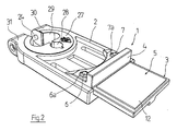
- die Befestigungsvorrichtung aus Figur 1 mit herausgefahrenem Verstellelement in perspektivischer Draufsicht;
- Figur 3
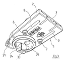
- die Befestigungsvorrichtung aus Figur 1 in perspektivischer Unteransicht;
- Figur 4
- die Befestigungsvorrichtung aus den Figuren 1 bis 3 in der Position gemäß Figur 2 in Unteransicht; und
- Figur 5
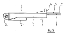
- die Befestigungsvorrichtung aus den Figuren 1 bis 4 in Seitenansicht;
- Figur 6
- die erfindungsgemäße Befestigungsvorrichtung in montierter Position in Seitenansicht;
- Figur 7
- die Befestigungsvorrichtung aus Figur 6 in geschnittener perspektivischer Seitenansicht;
- Figur 8
- die erfindungsgemäße Befestigungsvorrichtung bei Anschluss an eine alternative Armatur in Seitenansicht;
- Figur 9
- die Befestigungsvorrichtung aus Figur 8 in geschnittener perspektivischer Seitenansicht;
- Figur 10
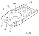
- einen Grundkörper der erfindungsgemäßen Befestigungsvorrichtung aus den vorgenannten Zeichnungen in perspektivischer Draufsicht und;
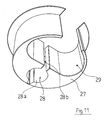
- Figur 11
- einen Einsatz zur Verwendung bei der erfindungsgemäßen Befestigungsvorrichtung aus den vorgenannten Zeichnungen.
- In Figur 1 ist eine erfindungsgemäße Befestigungsvorrichtung in perspektivischer Seitenansicht dargestellt. Die Befestigungsvorrichtung 1 besteht aus einem sich im eingebauten Zustand in Horizontalrichtung erstreckenden plattenförmigen Grundkörper 2 und einem diesem gegenüber in der Ebene des Grundkörpers verschiebbaren Verstellelement 3, welches eine vertikale Abstützfläche 4 und eine horizontale Abstützfläche 5 aufweist. Sowohl der Grundkörper als auch das Verstellelement bestehen aus einem stabilen und verwindungssteifen Kunststoff.
- Die Verschiebebewegung des Verstellelements 3 ist aus den Figuren 1 und 2 ersichtlich: Dort sieht man in Figur 1 das Verstellelement 3 in eingefahrener Position und in Figur 2 in maximal ausgefahrener Position, wobei aus den zugehörigen Unteransichten in den Figuren 3 und 4 erkennbar ist, dass die Verstellbewegung durch eine Nut-Schraubenverbindung geführt und beschränkt wird, indem zwei Schrauben 6, 7, die am Verstellelement 3 gelagert sind, entlang von zwei parallelen schlitzförmigen Nuten 8, 9 entlang eines Verschiebeweges in der Größenordnung von etwa 30 mm in der durch die Nuten 8, 9 vorgegebenen Richtung verschoben werden können. Die Schrauben und die Nuten ermöglichen eine stufenlose Arretierung des Verstellelements 3 in der gewünschten Position, in der dann lediglich die Schrauben 6, 7 gegenüber den am Verstellelement vorgesehenen entsprechenden Schraubenmuttern 6a, 7a angezogen werden müssen, woraufhin die Schraubenmuttern in Richtung der Schraubenköpfe gedrückt und so das Verstellelement am Grundkörper 2 festgelegt wird.
- Das Verstellelement weist - wie es aus Figur 4 ersichtlich ist - zwei Bohrungen 10, 11 auf, die zwei Befestigungsschrauben aufnehmen können, um die Befestigungsvorrichtung 1 bzw. das Verstellelement 2 an einer Arbeitsplattenunterseite festlegen zu können. Darüber hinaus ist auf der Oberseite des Verstellelements eine doppelseitige Klebefolie 12 vorgesehen, die für eine erste Fixierung des Feststellelements an der Arbeitsplatte sorgt, bevor die Schrauben in die Bohrungen 10, 11 eingesteckt und festgeschraubt werden.
- Dadurch dass die vertikale Abstützfläche 4 und die horizontale Abstützfläche 5 einen rechten Winkel zueinander aufweisen, kann sich die Befestigungsvorrichtung 1 sowohl an der Unterseite eines die zugehörige Spüle tragenden Möbels abstützen als auch mit der vertikalen Abstützfläche 4 gegen einen Möbelausschnitt für die Spüle gedrückt werden. Werden daraufhin die Befestigungsschrauben angezogen, durch die die Befestigungsvorrichtung 1 an der Arbeitsplatten- bzw. Möbelunterseite festgelegt werden kann, so sorgt die vertikale Abstützfläche für ein Verhindern einer Kippbewegung der Befestigungsvorrichtung bezogen auf Figur 1 im Uhrzeigersinn und die horizontale Abstützfläche für ein Verhindern einer Kippbewegung im Gegenuhrzeigersinn.
- Die Befestigungsvorrichtung 1 besteht neben dem in Figur 10 im Detail dargestellten Grundkörper 2 mit einer Vertiefung 12 für das Verstellelement vor allem auch aus einer etwa zylinderförmigen Aussparung 13 mit etwa kreisförmigem Querschnitt. Mittels dieser Aussparung 13 lässt sich die Befestigungsvorrichtung 1 und insbesondere die Grundplatte 2 auf eine Armatur aufschieben. Die Aussparung 13 weist eine umlaufende Aussparungskante 13a auf, die an dem dem Verstellelement gegenüberliegenden Ende des Grundkörpers auf der gesamten Höhe in einem Bereich 13b durchbrochen ist, um zwei Klemmbacken 30, 31 zu bilden, die in gewissem Maße abstandsveränderbar zueinander ausgebildet sind. Dadurch dass die beiden Klemmbacken 30, 31 von einer gemeinsamen Spannschraube 24 beaufschlagt sind, führt das Anziehen der Schraube 24 zu einer Abstandsverringerung der Klemmbacken, wodurch der Querschnitt der Aussparung verkleinert wird und die jeweils in die Aussparung eingeschobene Armatur festgeklemmt werden kann.
- Die Verwendung der erfindungsgemäßen Befestigungsvorrichtung ist beispielsweise in den Figuren 6 und 7 dargestellt: Dort ist neben der erfindungsgemäßen Befestigungsvorrichtung 1 eine Metallspüle 14 mit einer Metall-Armaturenbank 15 und einem Spülbecken 16 gezeigt. Die Spüle 14 ist auf eine Arbeitsplatte 17 so aufgelegt, dass sie eine Arbeitsplattenöffnung 18 abdeckt und dass zumindest das Spülbecken 16 in die Arbeitsplattenöffnung 18 nach unten hineinragt.
- Der Arbeitsplattenausschnitt 18 wird von einer sich in Vertikalrichtung erstreckenden Kante 19 begrenzt, die zusammen mit der Arbeitsplattenunterseite 20 einen ungefähr rechten Winkel bildet.
- Die Spüle 14 weist im Bereich ihrer Armaturenbank 15 eine kreisförmige Aussparung auf, durch die sich eine Armatur 21 erstreckt, die ausgehend von der Spüle in Vertikalrichtung nach oben sowie auch nach unten verläuft. Auf der Oberseite bzw. am oberen Ende der Armatur 21 sind insbesondere Wasserauslauf- und auch Betätigungsmittel wie beispielsweise Mischhebel etc. angeordnet, während auf der Spülenunterseite ein Gewindestutzen 22 vorgesehen ist, mit dessen Hilfe eine Befestigungsmutter 23 die Armatur an der Spüle 14 festlegt.
- Auf den Gewindestutzen 22 wird die erfindungsgemäße Befestigungsvorrichtung 1 von unten in Vertikalrichtung aufgeschoben bis in eine vertikale Höhenposition, in der das Verstellelement 3 mit seiner horizontalen Abstützfläche 5 an der Arbeitsplattenunterseite 20 bündig anliegt. In einem weiteren Schritt wird die Schraube 24 angezogen, um die Befestigungsvorrichtung 1 am Gewindestutzen 22 festzulegen, indem sich die die Aussparung 13 umgebende Grundplatten-Aussparungskante 13a an dem Gewindestutzen 22 anlegt und diesen über die genannte Klemmverbindung festlegt. Anschließend wird das Verstellelement 3 in Horizontalrichtung so weit in Richtung der Arbeitsplattenkante 19 verschoben, bis die vertikale Abstützfläche 4 in flächige Anlage an die Arbeitsplattenkante 19 gelangt. Hierauf werden die Schrauben 6, 7 angezogen und die Position des Verstellelements gegenüber der Arbeitsplatte 17 fixiert. Anschließend können die Befestigungsschrauben von unten durch die Bohrungen 10, 11 geschraubt werden, um das Verstellelement 3 und somit die gesamte Befestigungsvorrichtung 1 an der Arbeitsplatte 17 festzulegen.
- In den Figuren 8 und 9 ist eine alternative Ausführungsform dargestellt, bei der unter Verwendung derselben Befestigungsvorrichtung 1 eine Armatur 25 dadurch an der Armaturenbank 15 festgelegt ist, dass eine sich von der Armatur 25 nach unten erstreckende Gewindestange 26 nicht direkt von dem Aussparungsrand 13a beaufschlagt wird, sondern von einem in die Aussparung 13 eingesteckten Einsatz 27, dessen exakte Form insbesondere aus Figur 11 ersichtlich ist.
- Dieser Einsatz 27 weist eine im Wesentlichen zylinderförmige Aussparung 28 mit etwa kreisförmigem Querschnitt für die Gewindestange auf sowie eine weitere Aussparung 29 mit ungefähr ovalem Querschnitt, durch die sich beispielsweise eine Wasserleitung 30 (siehe Figur 9) erstrecken kann. Der Einsatz 27 ist einseitig in einem Bereich 28b durchbrochen, um ihn so nachgiebig zu gestalten, dass die Klemmkraft der Schraube 24 zu einer entsprechenden Klemmbeaufschlagung der Gewindestange 26 durch den Rand 28a der Aussparung 28 führt. Hierzu ist auch die Aussparung 28 einseitig durchbrochen, um die genannte Klemmbewegung nicht zu behindern.
- Zusammenfassend bietet die Erfindung den wesentlichen Vorteil, eine Befestigungsvorrichtung mit zwei in unterschiedliche Richtung orientierten Abstützflächen zur Verfügung zu stellen, die aufgrund eines besonders vorteilhaften Verstellmechanismus für eine dauerhafte und formschlüssige Verbindung der Befestigungsvorrichtung an dem jeweiligen Möbel und insbesondere am Arbeitsplattenausschnitt und an der Arbeitsplattenunterseite dient.
Claims (14)
- Befestigungsvorrichtung für Armaturen von Küchenspülen, wobei die Befestigungsvorrichtung einerseits an einem unterhalb der Küchenspüle (14) sich erstreckenden Bereich der Armatur (21, 25) und andererseits an einem die Küchenspüle (14) tragenden Möbel (17) festlegbar ist,
dadurch gekennzeichnet,
dass die Befestigungsvorrichtung (1) zwei sich in unterschiedlichen Ebenen erstreckende Abstützflächen (4, 5) für das Möbel aufweist, nämlich eine vertikale Abstützfläche (4) zur Beaufschlagung eines vertikalen Abschnittes (19) des Möbels (17) und eine horizontale Abstützfläche (5) zur zusätzlichen Beaufschlagung eines horizontalen Abschnitts (20) des Möbels (17). - Befestigungsvorrichtung nach zumindest Anspruch 1,
dadurch gekennzeichnet,
dass die vertikale und/oder die horizontale Abstützfläche (4, 5) verstellbar an der Befestigungsvorrichtung (1) angeordnet sind. - Befestigungsvorrichtung nach zumindest Anspruch 2,
dadurch gekennzeichnet,
dass die Befestigungsvorrichtung (1) ein in horizontaler Richtung positionsveränderbares Verstellelement (3) aufweist und dass das Verstellelement die vertikale und/oder horizontale Abstützfläche (4, 5) aufweist. - Befestigungsvorrichtung nach zumindest Anspruch 3,
dadurch gekennzeichnet,
dass das Verstellelement (3) in horizontaler Richtung insbesondere über einen Bereich in der Größenordnung von 30 mm verschieblich an der Befestigungsvorrichtung (1) angeordnet und stufenlos in verschiedenen Horizontalpositionen insbesondere über eine Schraubverbindung (6, 6a, 7, 7a) festlegbar ist. - Befestigungsvorrichtung nach zumindest einem der vorstehenden Ansprüche,
dadurch gekennzeichnet,
dass die Befestigungsvorrichtung (1) mit ihrem den Abstützflächen (4, 5) gegenüberliegenden freien Ende die Armatur (22, 25) formschlüssig umgreift und insbesondere über eine Klemmverbindung festlegt. - Befestigungsvorrichtung nach zumindest Anspruch 5,
dadurch gekennzeichnet,
dass die Befestigungsvorrichtung (1) eine im Wesentlichen kreisförmige Aussparung (13) zur formschlüssigen Beaufschlagung der Armatur (22, 25), insbesondere eines ihr unteres Ende bildenden und Wasserleitungen umgebenden Gewindestutzens (22) aufweist. - Befestigungsvorrichtung nach zumindest Anspruch 6,
dadurch gekennzeichnet,
dass die Aussparung (13) mit in Horizontalrichtung partiell durchbrochenem Aussparungsrand (13a) ausgebildet ist. - Befestigungsvorrichtung nach zumindest Anspruch 5,
dadurch gekennzeichnet,
dass die Klemmverbindung über eine Schraubverbindung (24) erfolgt. - Befestigungsvorrichtung nach zumindest Anspruch 6,
dadurch gekennzeichnet,
dass in der Aussparung (13) ein Einsatz (27) festlegbar ist zur Reduzierung des Durchmessers und/oder Veränderung der Form der Aussparung (13) zur Anpassung an den von der Befestigungsvorrichtung (1) festzulegenden Bereich der Armatur (22, 25) und/oder der Wasserleitungen. - Befestigungsvorrichtung nach zumindest Anspruch 9,
dadurch gekennzeichnet,
dass der Einsatz (27) in der Aussparung (13) lösbar befestigbar ist. - Befestigungsvorrichtung nach zumindest Anspruch 9,
dadurch gekennzeichnet,
dass der Einsatz (27) eine kleinere Aussparung (28) für eine Gewindestange (26) der zu befestigenden Armatur (25) und eine weitere, insbesondere größere Aussparung (29) zur Durchführung der Wasserleitungen (30) aufweist. - Befestigungsvorrichtung nach zumindest Anspruch 9,
dadurch gekennzeichnet,
dass der Einsatz (27) in Horizontalrichtung nachgiebig ausgeführt ist, so dass die Armatur (25, 26) über die Klemmverbindung unter Zwischenfügung des Einsatzes festlegbar ist. - Befestigungsvorrichtung nach zumindest einem der vorstehenden Ansprüche,
dadurch gekennzeichnet,
dass die Festlegungsposition der Befestigungsvorrichtung (1) an der Armatur (22, 25, 26) vertikal beabstandet von der Küchenspüle (14) ist. - Befestigungsvorrichtung nach zumindest einem der vorstehenden Ansprüche,
dadurch gekennzeichnet,
dass sich die Befestigungsvorrichtung (1) so ausgebildet ist, dass sie sich horizontal von der horizontalen Abstützfläche (20) des Möbels (17) zur Armatur (22, 25) erstreckt und auf dieser Höhenposition festlegbar ist.
Priority Applications (1)
| Application Number | Priority Date | Filing Date | Title |
|---|---|---|---|
| PL06019426T PL1770224T3 (pl) | 2005-09-29 | 2006-09-16 | Urządzenie mocujące do ustalania armatury do zlewozmywaka, który jest umieszczony w blacie kuchennym |
Applications Claiming Priority (1)
| Application Number | Priority Date | Filing Date | Title |
|---|---|---|---|
| DE102005046861.6A DE102005046861B4 (de) | 2005-09-29 | 2005-09-29 | Befestigungsvorrichtung für Armaturen von Küchenspülen |
Publications (2)
| Publication Number | Publication Date |
|---|---|
| EP1770224A1 true EP1770224A1 (de) | 2007-04-04 |
| EP1770224B1 EP1770224B1 (de) | 2015-12-09 |
Family
ID=37507576
Family Applications (1)
| Application Number | Title | Priority Date | Filing Date |
|---|---|---|---|
| EP06019426.3A Not-in-force EP1770224B1 (de) | 2005-09-29 | 2006-09-16 | Befestigungsvorrichtung zur Fixierung einer Armatur an einer Spüle, die an einer Arbeitsplatte angeordnet ist |
Country Status (4)
| Country | Link |
|---|---|
| EP (1) | EP1770224B1 (de) |
| DE (1) | DE102005046861B4 (de) |
| DK (1) | DK1770224T3 (de) |
| PL (1) | PL1770224T3 (de) |
Cited By (4)
| Publication number | Priority date | Publication date | Assignee | Title |
|---|---|---|---|---|
| EP2080838A2 (de) | 2008-01-18 | 2009-07-22 | Niro-Plan Ag | Befestigungsvorrichtung zum Fixieren einer Armatur an einer von einem Möbel getragenen Spüle |
| DE202009004785U1 (de) * | 2009-05-06 | 2010-09-23 | Hettich Holding Gmbh & Co. Ohg | Vorrichtung zur Ausgabe von Wasser |
| GB2481981A (en) * | 2010-07-12 | 2012-01-18 | Stephen W Finlay | Apparatus for fixing a tap to a surface |
| DE102021207776A1 (de) | 2021-07-21 | 2023-01-26 | BSH Hausgeräte GmbH | Anordnung mit einem Spülbecken und einem Wasserhahn sowie mit einer spezifischen Verspannvorrichtung, sowie Verfahren |
Citations (1)
| Publication number | Priority date | Publication date | Assignee | Title |
|---|---|---|---|---|
| EP1418282A2 (de) * | 2002-11-06 | 2004-05-12 | BLANCO GmbH + Co KG | Haltevorrichtung zum Haltern einer Armatur an einer Spüle, die an einer Arbeitsplatte angeordnet ist |
Family Cites Families (7)
| Publication number | Priority date | Publication date | Assignee | Title |
|---|---|---|---|---|
| US1626343A (en) * | 1924-07-18 | 1927-04-26 | Kersten Samuel | Mixing-valve support for laundry trays |
| US1838829A (en) * | 1930-02-24 | 1931-12-29 | H B Sherman Mfg Company | Mixing laundry faucet |
| US1813422A (en) * | 1930-09-20 | 1931-07-07 | Chase Companies Inc | Laundry tray faucet |
| US5135022A (en) * | 1991-01-17 | 1992-08-04 | Masco Corporation Of Indiana | Vertically adjustable valve fitting assembly for tubs |
| DE4345103C2 (de) * | 1993-02-01 | 1996-09-05 | Mannesmann Ag | Vorrichtung zur Befestigung von winkeligen Installationselementen |
| US5515882A (en) * | 1995-06-22 | 1996-05-14 | Hennis; Ronald H. | Apparatus for installation of a fixture on a surface |
| DE19841178A1 (de) * | 1998-09-09 | 2000-03-16 | Grohe Armaturen Friedrich | Auslaufarmatur mit Befestigungseinrichtung |
-
2005
- 2005-09-29 DE DE102005046861.6A patent/DE102005046861B4/de not_active Expired - Fee Related
-
2006
- 2006-09-16 EP EP06019426.3A patent/EP1770224B1/de not_active Not-in-force
- 2006-09-16 PL PL06019426T patent/PL1770224T3/pl unknown
- 2006-09-16 DK DK06019426.3T patent/DK1770224T3/en active
Patent Citations (1)
| Publication number | Priority date | Publication date | Assignee | Title |
|---|---|---|---|---|
| EP1418282A2 (de) * | 2002-11-06 | 2004-05-12 | BLANCO GmbH + Co KG | Haltevorrichtung zum Haltern einer Armatur an einer Spüle, die an einer Arbeitsplatte angeordnet ist |
Cited By (5)
| Publication number | Priority date | Publication date | Assignee | Title |
|---|---|---|---|---|
| EP2080838A2 (de) | 2008-01-18 | 2009-07-22 | Niro-Plan Ag | Befestigungsvorrichtung zum Fixieren einer Armatur an einer von einem Möbel getragenen Spüle |
| DE202009004785U1 (de) * | 2009-05-06 | 2010-09-23 | Hettich Holding Gmbh & Co. Ohg | Vorrichtung zur Ausgabe von Wasser |
| GB2481981A (en) * | 2010-07-12 | 2012-01-18 | Stephen W Finlay | Apparatus for fixing a tap to a surface |
| DE102021207776A1 (de) | 2021-07-21 | 2023-01-26 | BSH Hausgeräte GmbH | Anordnung mit einem Spülbecken und einem Wasserhahn sowie mit einer spezifischen Verspannvorrichtung, sowie Verfahren |
| WO2023001572A1 (de) | 2021-07-21 | 2023-01-26 | BSH Hausgeräte GmbH | Anordnung mit einem spülbecken und einem wasserhahn sowie mit einer spezifischen verspannvorrichtung, sowie verfahren |
Also Published As
| Publication number | Publication date |
|---|---|
| DE102005046861A1 (de) | 2007-04-05 |
| PL1770224T3 (pl) | 2016-06-30 |
| DE102005046861B4 (de) | 2019-02-28 |
| EP1770224B1 (de) | 2015-12-09 |
| DK1770224T3 (en) | 2016-02-29 |
Similar Documents
| Publication | Publication Date | Title |
|---|---|---|
| AT10883U1 (de) | Befestigungsvorrichtung mit einer klemmvorrichtung | |
| DE202007005020U1 (de) | Mehrzweck-Stützgestell | |
| EP1770224B1 (de) | Befestigungsvorrichtung zur Fixierung einer Armatur an einer Spüle, die an einer Arbeitsplatte angeordnet ist | |
| EP2224177B1 (de) | Hals- und Justiervorrichtung für Heizkörper | |
| DE19606713A1 (de) | Schubkasten | |
| DE29901583U1 (de) | Höhenverstellbare Rohrhalterung | |
| AT5105U1 (de) | Montagerahmen zur befestigung eines sanitärapparates | |
| DE3444994C2 (de) | Verstellbarer Scharnierarm | |
| DE202023104791U1 (de) | Gleithülsenstruktur | |
| CH690357A5 (de) | Rohranfasgerät. | |
| DE9416530U1 (de) | Einrichtung zum Abstützen einer Arbeitsplatte an einer Wand o.dgl. | |
| DE4336141C2 (de) | Montagevorrichtung für eine an einer Arbeits- oder Tischplatte anbaubare Trageinrichtung, insbesondere eine Monitor-Trageinrichtung bzw. Monitor-Schwenkarm | |
| EP1257185A1 (de) | Verbindungselement für ein möbelstück, insbesondere für einen tisch | |
| EP1371788B1 (de) | Montagegestell für Sanitärapparate | |
| DE20304749U1 (de) | Tragvorrichtung für einen Sanitärkörper | |
| EP4030103B1 (de) | Kochfeld mit steuerungsgehäuse | |
| EP1137352B1 (de) | Vorrichtung zum verbinden einer tischplatte mit einem tischbein | |
| DE10251569A1 (de) | Haltevorrichtung zum Haltern einer Armatur an einer Spüle, die an einer Arbeitsplatte angeordnet ist | |
| DE202010000963U1 (de) | Duschablaufanordnung | |
| DE29608455U1 (de) | Befestigungsvorrichtung, nämlich für Bretter, Regalbretter o.dgl. | |
| DE4040747A1 (de) | Hoehenverstellbare aufhaengung | |
| DE9403872U1 (de) | Rohrschelle | |
| EP4480466A1 (de) | Verbindungsmittel zur verbindung eines ersten teils mit einem rechteckrohr oder -balken | |
| DE102022125476A1 (de) | Befestigungsvorrichtung für ein Werkstück | |
| EP2065521B1 (de) | Befestigungssystem zur Befestigung eines Geräteeinsatzes in einer Einbauöffnung einer Arbeitsplatte. |
Legal Events
| Date | Code | Title | Description |
|---|---|---|---|
| PUAI | Public reference made under article 153(3) epc to a published international application that has entered the european phase |
Free format text: ORIGINAL CODE: 0009012 |
|
| AK | Designated contracting states |
Kind code of ref document: A1 Designated state(s): AT BE BG CH CY CZ DE DK EE ES FI FR GB GR HU IE IS IT LI LT LU LV MC NL PL PT RO SE SI SK TR |
|
| AX | Request for extension of the european patent |
Extension state: AL BA HR MK YU |
|
| 17P | Request for examination filed |
Effective date: 20070821 |
|
| 17Q | First examination report despatched |
Effective date: 20070920 |
|
| AKX | Designation fees paid |
Designated state(s): AT BE BG CH CY CZ DE DK EE ES FI FR GB GR HU IE IS IT LI LT LU LV MC NL PL PT RO SE SI SK TR |
|
| RAP1 | Party data changed (applicant data changed or rights of an application transferred) |
Owner name: FRANKE TECHNOLOGY AND TRADEMARK LTD |
|
| GRAP | Despatch of communication of intention to grant a patent |
Free format text: ORIGINAL CODE: EPIDOSNIGR1 |
|
| INTG | Intention to grant announced |
Effective date: 20150810 |
|
| GRAS | Grant fee paid |
Free format text: ORIGINAL CODE: EPIDOSNIGR3 |
|
| GRAA | (expected) grant |
Free format text: ORIGINAL CODE: 0009210 |
|
| AK | Designated contracting states |
Kind code of ref document: B1 Designated state(s): AT BE BG CH CY CZ DE DK EE ES FI FR GB GR HU IE IS IT LI LT LU LV MC NL PL PT RO SE SI SK TR |
|
| REG | Reference to a national code |
Ref country code: GB Ref legal event code: FG4D Free format text: NOT ENGLISH |
|
| REG | Reference to a national code |
Ref country code: AT Ref legal event code: REF Ref document number: 764644 Country of ref document: AT Kind code of ref document: T Effective date: 20151215 Ref country code: CH Ref legal event code: EP |
|
| REG | Reference to a national code |
Ref country code: IE Ref legal event code: FG4D Free format text: LANGUAGE OF EP DOCUMENT: GERMAN |
|
| REG | Reference to a national code |
Ref country code: DE Ref legal event code: R096 Ref document number: 502006014661 Country of ref document: DE |
|
| REG | Reference to a national code |
Ref country code: DK Ref legal event code: T3 Effective date: 20160223 |
|
| REG | Reference to a national code |
Ref country code: SE Ref legal event code: TRGR |
|
| REG | Reference to a national code |
Ref country code: LT Ref legal event code: MG4D |
|
| REG | Reference to a national code |
Ref country code: NL Ref legal event code: FP |
|
| PG25 | Lapsed in a contracting state [announced via postgrant information from national office to epo] |
Ref country code: ES Free format text: LAPSE BECAUSE OF FAILURE TO SUBMIT A TRANSLATION OF THE DESCRIPTION OR TO PAY THE FEE WITHIN THE PRESCRIBED TIME-LIMIT Effective date: 20151209 Ref country code: LT Free format text: LAPSE BECAUSE OF FAILURE TO SUBMIT A TRANSLATION OF THE DESCRIPTION OR TO PAY THE FEE WITHIN THE PRESCRIBED TIME-LIMIT Effective date: 20151209 |
|
| PG25 | Lapsed in a contracting state [announced via postgrant information from national office to epo] |
Ref country code: GR Free format text: LAPSE BECAUSE OF FAILURE TO SUBMIT A TRANSLATION OF THE DESCRIPTION OR TO PAY THE FEE WITHIN THE PRESCRIBED TIME-LIMIT Effective date: 20160310 Ref country code: LV Free format text: LAPSE BECAUSE OF FAILURE TO SUBMIT A TRANSLATION OF THE DESCRIPTION OR TO PAY THE FEE WITHIN THE PRESCRIBED TIME-LIMIT Effective date: 20151209 |
|
| PG25 | Lapsed in a contracting state [announced via postgrant information from national office to epo] |
Ref country code: IS Free format text: LAPSE BECAUSE OF FAILURE TO SUBMIT A TRANSLATION OF THE DESCRIPTION OR TO PAY THE FEE WITHIN THE PRESCRIBED TIME-LIMIT Effective date: 20151209 |
|
| PG25 | Lapsed in a contracting state [announced via postgrant information from national office to epo] |
Ref country code: CZ Free format text: LAPSE BECAUSE OF FAILURE TO SUBMIT A TRANSLATION OF THE DESCRIPTION OR TO PAY THE FEE WITHIN THE PRESCRIBED TIME-LIMIT Effective date: 20151209 |
|
| PG25 | Lapsed in a contracting state [announced via postgrant information from national office to epo] |
Ref country code: RO Free format text: LAPSE BECAUSE OF FAILURE TO SUBMIT A TRANSLATION OF THE DESCRIPTION OR TO PAY THE FEE WITHIN THE PRESCRIBED TIME-LIMIT Effective date: 20151209 Ref country code: PT Free format text: LAPSE BECAUSE OF FAILURE TO SUBMIT A TRANSLATION OF THE DESCRIPTION OR TO PAY THE FEE WITHIN THE PRESCRIBED TIME-LIMIT Effective date: 20160411 Ref country code: SK Free format text: LAPSE BECAUSE OF FAILURE TO SUBMIT A TRANSLATION OF THE DESCRIPTION OR TO PAY THE FEE WITHIN THE PRESCRIBED TIME-LIMIT Effective date: 20151209 Ref country code: EE Free format text: LAPSE BECAUSE OF FAILURE TO SUBMIT A TRANSLATION OF THE DESCRIPTION OR TO PAY THE FEE WITHIN THE PRESCRIBED TIME-LIMIT Effective date: 20151209 Ref country code: IS Free format text: LAPSE BECAUSE OF FAILURE TO SUBMIT A TRANSLATION OF THE DESCRIPTION OR TO PAY THE FEE WITHIN THE PRESCRIBED TIME-LIMIT Effective date: 20160409 |
|
| REG | Reference to a national code |
Ref country code: DE Ref legal event code: R097 Ref document number: 502006014661 Country of ref document: DE |
|
| REG | Reference to a national code |
Ref country code: FR Ref legal event code: PLFP Year of fee payment: 11 |
|
| PLBE | No opposition filed within time limit |
Free format text: ORIGINAL CODE: 0009261 |
|
| STAA | Information on the status of an ep patent application or granted ep patent |
Free format text: STATUS: NO OPPOSITION FILED WITHIN TIME LIMIT |
|
| 26N | No opposition filed |
Effective date: 20160912 |
|
| PG25 | Lapsed in a contracting state [announced via postgrant information from national office to epo] |
Ref country code: SI Free format text: LAPSE BECAUSE OF FAILURE TO SUBMIT A TRANSLATION OF THE DESCRIPTION OR TO PAY THE FEE WITHIN THE PRESCRIBED TIME-LIMIT Effective date: 20151209 |
|
| PG25 | Lapsed in a contracting state [announced via postgrant information from national office to epo] |
Ref country code: MC Free format text: LAPSE BECAUSE OF FAILURE TO SUBMIT A TRANSLATION OF THE DESCRIPTION OR TO PAY THE FEE WITHIN THE PRESCRIBED TIME-LIMIT Effective date: 20151209 |
|
| REG | Reference to a national code |
Ref country code: IE Ref legal event code: MM4A |
|
| PG25 | Lapsed in a contracting state [announced via postgrant information from national office to epo] |
Ref country code: IE Free format text: LAPSE BECAUSE OF NON-PAYMENT OF DUE FEES Effective date: 20160916 |
|
| PG25 | Lapsed in a contracting state [announced via postgrant information from national office to epo] |
Ref country code: LU Free format text: LAPSE BECAUSE OF NON-PAYMENT OF DUE FEES Effective date: 20160916 |
|
| REG | Reference to a national code |
Ref country code: FR Ref legal event code: PLFP Year of fee payment: 12 |
|
| REG | Reference to a national code |
Ref country code: AT Ref legal event code: MM01 Ref document number: 764644 Country of ref document: AT Kind code of ref document: T Effective date: 20160916 |
|
| PG25 | Lapsed in a contracting state [announced via postgrant information from national office to epo] |
Ref country code: AT Free format text: LAPSE BECAUSE OF NON-PAYMENT OF DUE FEES Effective date: 20160916 |
|
| PG25 | Lapsed in a contracting state [announced via postgrant information from national office to epo] |
Ref country code: CY Free format text: LAPSE BECAUSE OF FAILURE TO SUBMIT A TRANSLATION OF THE DESCRIPTION OR TO PAY THE FEE WITHIN THE PRESCRIBED TIME-LIMIT Effective date: 20151209 Ref country code: HU Free format text: LAPSE BECAUSE OF FAILURE TO SUBMIT A TRANSLATION OF THE DESCRIPTION OR TO PAY THE FEE WITHIN THE PRESCRIBED TIME-LIMIT; INVALID AB INITIO Effective date: 20060916 |
|
| PG25 | Lapsed in a contracting state [announced via postgrant information from national office to epo] |
Ref country code: BG Free format text: LAPSE BECAUSE OF FAILURE TO SUBMIT A TRANSLATION OF THE DESCRIPTION OR TO PAY THE FEE WITHIN THE PRESCRIBED TIME-LIMIT Effective date: 20151209 |
|
| REG | Reference to a national code |
Ref country code: FR Ref legal event code: PLFP Year of fee payment: 13 |
|
| PGFP | Annual fee paid to national office [announced via postgrant information from national office to epo] |
Ref country code: DK Payment date: 20190920 Year of fee payment: 14 Ref country code: NL Payment date: 20190923 Year of fee payment: 14 Ref country code: SE Payment date: 20190924 Year of fee payment: 14 Ref country code: FI Payment date: 20190918 Year of fee payment: 14 Ref country code: IT Payment date: 20190920 Year of fee payment: 14 |
|
| PGFP | Annual fee paid to national office [announced via postgrant information from national office to epo] |
Ref country code: PL Payment date: 20190910 Year of fee payment: 14 |
|
| PGFP | Annual fee paid to national office [announced via postgrant information from national office to epo] |
Ref country code: BE Payment date: 20190923 Year of fee payment: 14 |
|
| PGFP | Annual fee paid to national office [announced via postgrant information from national office to epo] |
Ref country code: GB Payment date: 20201123 Year of fee payment: 15 Ref country code: CH Payment date: 20201124 Year of fee payment: 15 Ref country code: FR Payment date: 20201116 Year of fee payment: 15 |
|
| REG | Reference to a national code |
Ref country code: FI Ref legal event code: MAE |
|
| REG | Reference to a national code |
Ref country code: DK Ref legal event code: EBP Effective date: 20200930 |
|
| PG25 | Lapsed in a contracting state [announced via postgrant information from national office to epo] |
Ref country code: FI Free format text: LAPSE BECAUSE OF NON-PAYMENT OF DUE FEES Effective date: 20200916 |
|
| REG | Reference to a national code |
Ref country code: NL Ref legal event code: MM Effective date: 20201001 |
|
| PGFP | Annual fee paid to national office [announced via postgrant information from national office to epo] |
Ref country code: TR Payment date: 20201210 Year of fee payment: 15 |
|
| REG | Reference to a national code |
Ref country code: BE Ref legal event code: MM Effective date: 20200930 |
|
| PG25 | Lapsed in a contracting state [announced via postgrant information from national office to epo] |
Ref country code: NL Free format text: LAPSE BECAUSE OF NON-PAYMENT OF DUE FEES Effective date: 20201001 |
|
| PG25 | Lapsed in a contracting state [announced via postgrant information from national office to epo] |
Ref country code: BE Free format text: LAPSE BECAUSE OF NON-PAYMENT OF DUE FEES Effective date: 20200930 Ref country code: SE Free format text: LAPSE BECAUSE OF NON-PAYMENT OF DUE FEES Effective date: 20200917 |
|
| REG | Reference to a national code |
Ref country code: SE Ref legal event code: EUG |
|
| PG25 | Lapsed in a contracting state [announced via postgrant information from national office to epo] |
Ref country code: IT Free format text: LAPSE BECAUSE OF NON-PAYMENT OF DUE FEES Effective date: 20200916 |
|
| PG25 | Lapsed in a contracting state [announced via postgrant information from national office to epo] |
Ref country code: DK Free format text: LAPSE BECAUSE OF NON-PAYMENT OF DUE FEES Effective date: 20200930 |
|
| REG | Reference to a national code |
Ref country code: CH Ref legal event code: PL |
|
| GBPC | Gb: european patent ceased through non-payment of renewal fee |
Effective date: 20210916 |
|
| PG25 | Lapsed in a contracting state [announced via postgrant information from national office to epo] |
Ref country code: TR Free format text: LAPSE BECAUSE OF NON-PAYMENT OF DUE FEES Effective date: 20210916 |
|
| PG25 | Lapsed in a contracting state [announced via postgrant information from national office to epo] |
Ref country code: GB Free format text: LAPSE BECAUSE OF NON-PAYMENT OF DUE FEES Effective date: 20210916 Ref country code: FR Free format text: LAPSE BECAUSE OF NON-PAYMENT OF DUE FEES Effective date: 20210930 |
|
| PG25 | Lapsed in a contracting state [announced via postgrant information from national office to epo] |
Ref country code: LI Free format text: LAPSE BECAUSE OF NON-PAYMENT OF DUE FEES Effective date: 20210930 Ref country code: CH Free format text: LAPSE BECAUSE OF NON-PAYMENT OF DUE FEES Effective date: 20210930 |
|
| PG25 | Lapsed in a contracting state [announced via postgrant information from national office to epo] |
Ref country code: PL Free format text: LAPSE BECAUSE OF NON-PAYMENT OF DUE FEES Effective date: 20200916 |
|
| P01 | Opt-out of the competence of the unified patent court (upc) registered |
Effective date: 20230602 |
|
| PGFP | Annual fee paid to national office [announced via postgrant information from national office to epo] |
Ref country code: DE Payment date: 20230829 Year of fee payment: 18 |
|
| REG | Reference to a national code |
Ref country code: DE Ref legal event code: R119 Ref document number: 502006014661 Country of ref document: DE |
|
| PG25 | Lapsed in a contracting state [announced via postgrant information from national office to epo] |
Ref country code: DE Free format text: LAPSE BECAUSE OF NON-PAYMENT OF DUE FEES Effective date: 20250401 |