EP1767582B1 - Composition élastomère fortement diélectrique et antenne diélectrique - Google Patents
Composition élastomère fortement diélectrique et antenne diélectrique Download PDFInfo
- Publication number
- EP1767582B1 EP1767582B1 EP05751264A EP05751264A EP1767582B1 EP 1767582 B1 EP1767582 B1 EP 1767582B1 EP 05751264 A EP05751264 A EP 05751264A EP 05751264 A EP05751264 A EP 05751264A EP 1767582 B1 EP1767582 B1 EP 1767582B1
- Authority
- EP
- European Patent Office
- Prior art keywords
- dielectric
- antenna
- highly
- ceramic powder
- dielectric constant
- Prior art date
- Legal status (The legal status is an assumption and is not a legal conclusion. Google has not performed a legal analysis and makes no representation as to the accuracy of the status listed.)
- Expired - Fee Related
Links
Images

Classifications
-
- C—CHEMISTRY; METALLURGY
- C08—ORGANIC MACROMOLECULAR COMPOUNDS; THEIR PREPARATION OR CHEMICAL WORKING-UP; COMPOSITIONS BASED THEREON
- C08L—COMPOSITIONS OF MACROMOLECULAR COMPOUNDS
- C08L101/00—Compositions of unspecified macromolecular compounds
- C08L101/12—Compositions of unspecified macromolecular compounds characterised by physical features, e.g. anisotropy, viscosity or electrical conductivity
-
- C—CHEMISTRY; METALLURGY
- C08—ORGANIC MACROMOLECULAR COMPOUNDS; THEIR PREPARATION OR CHEMICAL WORKING-UP; COMPOSITIONS BASED THEREON
- C08K—Use of inorganic or non-macromolecular organic substances as compounding ingredients
- C08K3/00—Use of inorganic substances as compounding ingredients
- C08K3/18—Oxygen-containing compounds, e.g. metal carbonyls
- C08K3/24—Acids; Salts thereof
-
- H—ELECTRICITY
- H01—ELECTRIC ELEMENTS
- H01Q—ANTENNAS, i.e. RADIO AERIALS
- H01Q9/00—Electrically-short antennas having dimensions not more than twice the operating wavelength and consisting of conductive active radiating elements
- H01Q9/04—Resonant antennas
- H01Q9/0407—Substantially flat resonant element parallel to ground plane, e.g. patch antenna
Definitions
- the present invention relates to a highly dielectric elastomer composition and an electrode-provided dielectric antenna mounted on a molding of the highly dielectric elastomer composition, and more particularly to a highly dielectric elastomer composition for use in electric and electronic parts used at a high-frequency band and the dielectric antenna.
- the dielectric constant of a material of an antenna incorporated in the communication apparatus becomes higher, it is possible to make the communication signal higher and the communication apparatus compact.
- the dielectric constant is a parameter indicating the degree of a polarization inside the dielectric. Therefore when the material of the antenna having a high dielectric constant can be used, it is possible to make the frequency of the communication signal high and hence shorten circuits and make the communication apparatus compact.
- the fibrous metal salt of titanic acid and/or the composite fiber of the metal salt of titanic acid and the amorphous titanium oxide integrally enclosing the fibrous metal salt of titanic acid therewith to form the integrated composite fiber are known.
- the integrated composite fiber having the mol ratio between metals M and Ti in the range of 1.005 to 1.5 is mixed with the elastomer at 5 to 80 wt% with respect to the total weight of the highly dielectric elastomer composition to allow the highly dielectric elastomer composition to have a high permittivity (patent document 1).
- the high-permittivity rubber composition (patent document 2) is an insulating material which is disposed to relax an electric field mismatching which is liable to be generated at a connection position of power cables, a termination portion thereof, and the like.
- As the property of the barium titanate powder it has a large dielectric loss tangent. Thus the barium titanate powder is unsuitable for an electronic part such the material of an antenna.
- the communication apparatus As the use mode of the communication apparatus becomes diversified, the communication apparatus is demanded to have little variations in the electrical characteristic in the range from a low temperature to a high temperature.
- the conventional highly dielectric elastomer composition is used for an electronic part that is used in a wide temperature region, the electrical characteristic of the electronic part changes greatly.
- an antenna body is formed by molding a dielectric resin material which has a small specific gravity and a small dielectric loss and is advantageous for obtaining a high gain, and an electrode is formed on the obtained molding to form a dielectric antenna.
- the rubber-like elastic material soluble in the inorganic filler and in the solvent is mixed with the styrene polymer having the syndiotactic structure (SPS) to obtain the composite dielectric material, the surface of which is roughened by etching treatment to plate the surface at an improved degree.
- the composite dielectric material is used as an antenna (patent document 3).
- a resin difficult to be plated and a resin easy to be plated are used in combination.
- the resin easy to be plated is used on the surface on which the electrode is formed so that it is used as the material of the antenna (patent document 4) .
- the electrode is made of the copper foil pattern (patent document 5) .
- the electrode is formed on the antenna body made of ceramics by screen printing (patent document 6).
- a resin material When a resin material is used as a dielectric substrate of an antenna, it is necessary to form an electrode.
- a metal plating method As methods of forming the electrode, a metal plating method, a metal foil-bonding method, and screen printing method, and the like are known. Metal plating treatment is difficult to be made . Further the metal plating treatment has a problem that a specific foundation treatment is required, as disclosed in the patent documents 3 and 4. Further when the electrode is formed by plating treatment, the electrode has a low degree of adhesion to the material of the antenna to a low degree after the foundation treatment is made. Thus there is a fear that the dielectric characteristic deteriorates. Thus the metal plating processing is unfavorable.
- the electrode When the copper foil is used as the electrode, as disclosed in the patent document 5, the electrode is liable to be oxidized. Thus when a working temperature rises, the electrode is oxidized and the permittivity decreases.
- the screen printing is applied to form the electrode on the antenna body made of ceramics but not applied to the antenna body made of the elastomer.
- Screen printing paste used to form the electrode of the antenna made of ceramics contains silica.
- a product including the printed paste is calcined at a high temperature of 500 to 600°C to vitrify it so that Ag powder is fixed. Because the elastomer is decomposed at a high temperature of 500°C, the screen printing method cannot be used for the antenna composed of the elastomer.
- Patent document 1 Japanese Patent Application Laid-Open No. 09-031244
- Patent document 2 Japanese Patent Application Laid-Open No. 2003-138067
- Patent document 3 Japanese Patent Application Laid-Open No. 2001-143531
- Patent document 4 Japanese Patent Application Laid-Open No. 2003-078322
- Patent document 5 Japanese Patent. Application Laid-Open No. 07-066620
- Patent document 6 Japanese Patent Application Laid-Open No. 06-029727
- JP2003128930 discloses a composite dielectric material in which dielectric ceramics are dispersed in an organic polymer resin.
- the dielectric material has a particular dielectric constant in the high frequency GHz band, while maintaining a high Q value.
- a highly dielectric elastomer composition of the present invention includes an elastomer and a highly dielectric ceramic powder mixed with the elastomer.
- the highly dielectric ceramic powder has a temperature coefficient ⁇ (unit: 1/°C) of a dielectric constant of the ceramic powder on 25°C standard ranging from -200 ⁇ 10 -6 to 100 ⁇ 10 -6 over a temperature range from -40°C to 100°C.
- ⁇ r (t) and ⁇ r (25) indicate the dielectric constant at a given temperature t°C in the range of -40°C to 100°C and the dielectric constant at 25°C respectively.
- the dielectric constant of the highly dielectric elastomer composition is not less than seven and a dielectric loss tangent thereof is not more than 0.01.
- the highly dielectric ceramic powder is a barium titanate-neodymium ceramic powder.
- the elastomer contains a non-polar olefin unit as a constituent unit thereof.
- the elastomer is an ethylene propylene rubber.
- a dielectric antenna of the present invention includes a molding of the highly dielectric elastomer composition and an electrode formed on the molding.
- the electrode is made of a plated copper foil.
- the electrode is formed by screen-printing by using conductive paste.
- the highly dielectric ceramic powder in which the temperature coefficient ⁇ (unit: 1/°C) of the dielectric constant is in the range of -200 ⁇ 10 -6 to 100 ⁇ 10 -6 in the temperature range of -40°C to 100°C is mixed into the elastomer.
- the barium titanate-neodymium ceramic powder is used.
- the dielectric antenna of the present invention is obtained by bonding the copper foil plated as the electrode thereof to the molding of the highly dielectric elastomer composition formed as the body thereof or by bonding the conductive paste thereto by screen printing. Consequently it is possible to make the antenna compact. Further because the antenna has a high permittivity, it is possible to realize a high-frequency communication apparatus in which the antenna is incorporated and make communication apparatus compact.
- the dielectric constant of the elastomer composition changes.
- the resonance frequency of the antenna shifts.
- the dielectric constant of the elastomer composition drops with a rise of temperature
- the resonance frequency of the antenna shifts to a high-frequency side.
- the amount of the shift can be computed with reference to equations (1) through (6) shown below.
- the highly dielectric elastomer composition has a small temperature coefficient ⁇ of the dielectric constant thereof, when it is used as the material of the antenna.
- the highly dielectric ceramic powder having the temperature coefficient a in the range of -200 ⁇ 10 -6 ⁇ 100 ⁇ 10 -6 , favorably-100 ⁇ 10 -6 ⁇ 30 ⁇ 10 -6 , and more favorably -50 ⁇ 10 -6 ⁇ 30 ⁇ 10 -6 it is possible to set the temperature coefficient ⁇ of the dielectric constant of the highly dielectric elastomer composition to -1500 ⁇ 10 -6 ⁇ ⁇ ⁇ 100 ⁇ 10 -6 , and favorably -1200 ⁇ 10 -6 ⁇ ⁇ ⁇ 50 ⁇ 10 -6 .
- the temperature coefficient ⁇ of the highly dielectric ceramic powder is less than -200 ⁇ 10 -6 , because the shift of the resonance frequency with respect to the operating frequency becomes larger than ⁇ 10%, when the highly dielectric ceramic powder is used as the material of the antenna.
- the elastomer of the highly dielectric elastomer composition of the present invention it is possible to use natural rubber and/or synthetic rubber.
- elastomers consisting of the natural rubber it is possible to list graft modified rubber formed by grafting a double bond of natural rubber, chlorinated rubber, rubber hydrochloride, cyclized rubber, maleic rubber or hydrogenated rubber with a vinyl monomer such as methyl methacrylate, acrylonitrile or ester methacrylate; a block polymer formed by kneading the natural rubber in the presence of a monomer in nitrogen current.
- elastomers containing synthetic cis-1,4-polyisoprene as a material thereof.
- elastomers consisting of the synthetic rubber it is possible to list elastomer of the polyolefin family such as isobutylene rubber, ethylene propylene rubber, ethylene propylene diene rubber, ethylene propylene terpolymer, chlorosulfonated polyethylene rubber, and the like; elastomers of the styrene family such as styrene-isoprene-styrene block copolymer (SIS), styrene-butadiene-styrene copolymer (SBS), styrene-ethylene-butylene-styrene block copolymer (SEBS), and the like; isoprene rubber, urethane rubber, epichlorohidrin rubber, silicone rubber, nylon 12, butyl rubber, butadiene rubber, polynorbornane rubber, acrylonitrile-butadiene rubber, and the like.
- SIS styrene-isopre
- thermoplastic resins can be used in combination with these elastomers within a range in which the elasticity of the elastomers do not deteriorate.
- a highly dielectric elastomer excellent in its electrical insulating property can be obtained.
- EPDM ethylene propylene rubber
- isobutylene rubber isoprene rubber
- silicone rubber silicone rubber
- the EPDM and the ethylene propylene diene rubber have a very low dielectric loss tangent respectively, they canbe preferably used for electronic parts such as an antenna and a sensor.
- ceramic powder consisting of a metal salt of titanic acid in which at least one kind of the rare earth metal such as neodymium (Nd), lanthanum (La), and the like, and one or not less than two metal elements selected from among barium (Ba), strontium (Sr), calcium (Ca), magnesium (Mg), cobalt (Co), palladium (Pd), zinc (Zn), beryllium (Be), cadmium (Cd), and bismuth (Bi).
- the rare earth metals such as Nd, La contribute to the improvement of a temperature characteristic that the dielectric constant makes a low degree of change with a temperature change.
- Metal elements such as Ba, Sr enhance the permittivity and decrease the dielectric loss tangent. That is, they contribute to the improvement of the dielectric characteristic.
- barium titanate ⁇ neodymium ceramic powder containing Ti, Ba, Nd, and Bi can be used as preferable highly dielectric ceramic powder.
- the particle diameter of the ceramic powder having a high permittivity and a low dielectric loss tangent is 0.01 to 100 ⁇ m. It is unpreferable that the average particle diameter is less than 0.01 ⁇ m, because the ceramic powder scatters at a measuring time and hence it is difficult to treat the ceramic powder. It is unpreferable that the average particle diameter of the ceramic powder is more than 100 ⁇ m, because there is a fear that a variation of the dielectric characteristic is caused inside the molding. A more practicable range is 0.1 to 20 ⁇ m.
- the dielectric constant thereof is not less than seven, and the dielectric loss tangent thereof is not more than 0.01.
- the dielectric constant of the highly dielectric elastomer composition is not less than seven and the dielectric loss tangent thereof is not more than 0.01. It is unpreferable that the dielectric constant of the highly dielectric elastomer composition is less than seven, because the effect of decreasing the wavelength of a signal propagating in a material of an electronic part is and thus it is impossible to make a product compact. It is unpreferable that the dielectric loss tangent of the highly dielectric elastomer composition is more than 0.01, because a loss inside the material of the electronic part is large.
- the material of the electronic part can be used in a high-frequency band of not less than 100 MHz.
- the mixing ratio of the highly dielectric ceramic powder is so selected as to keep the dielectric constant of the highly dielectric elastomer composition at not less than seven, the dielectric loss tangent thereof at notmore than 0.01, set the temperature coefficient ⁇ of the dielectric constant thereof to the range of -1500 ⁇ 10 -6 ⁇ 100 ⁇ 10 -6 , and allow the highly dielectric elastomer composition to have a moldability to such an extent that the highly dielectric elastomer composition can be formed into an electronic part such as an antenna.
- the mixing amount of the highly dielectric ceramic powder is 300 to 1200 parts by weight (phr) per 100 parts by weight (phr) of the elastomer.
- the highly dielectric elastomer composition which can be used in the present invention is capable of containing (1) : a coupling agent such as a silane-containing coupling agent, a titanate-containing coupling agent, a zirconia ⁇ aluminate-containing coupling agent for improving affinity and cementing performance in the interface of the elastomer and the ceramic powder and improving the mechanical strength of the highly dielectric elastomer composition, (2): a filler consisting of fine particles such as talc, calcium pyrophosphate, and the like for improving plating performance for forming an electrode, (3): an antioxidant for improving heat stability thereof to a high extent, (4): a light stabilizer such as an ultraviolet light absorber for improving light resistance thereof, (5): a halogen-containing fire-retardant assistant or a phosphorus-containing fire-retardant assistant for improving the fire-retardant property thereof, (6)
- a coupling agent such as a silane-containing coupling agent, a titanate-containing coupling
- the highly dielectric elastomer composition of the present invention is capable of containing fibers of an alkali metal salt of titanic acid such as glass fiber, a whisker of potassium titanate, and the like; fibers of a metal salt of boric acid such as fibers of titanium oxide, a whisker of magnesium borate, a whisker of aluminum borate, and the like; fibers of a metal salt of silicic acid such as a whisker of zinc silicate, a whisker of magnesium silicate; and organic and inorganic fillers such as carbon fibers, alumina fibers, aramid fibers.
- an alkali metal salt of titanic acid such as glass fiber, a whisker of potassium titanate, and the like
- fibers of a metal salt of boric acid such as fibers of titanium oxide, a whisker of magnesium borate, a whisker of aluminum borate, and the like
- fibers of a metal salt of silicic acid such as a whisker of zinc silicate, a whisker of magnesium silicate
- the method of producing the highly dielectric elastomer composition of the present invention is not limited to a specific method, but it is possible to use various mixing and molding methods .
- the highly dielectric elastomer composition maybe directly formed into a product by inj ectionmolding, extrusionmolding, and the like or formed into a to-be-moldedmaterial such as a pellet, a rod-shaped material, a plate-shaped material.
- the method of producing the dielectric antenna of the present invention from the highly dielectric elastomer composition is not limited to a specific method either, but it is possible to use the above-described various mixing and molding methods.
- the surface of the material of the antenna may be roughened with sand paper or blast treatment or surface-treated by etching with a solvent, UV etching, plasma etching, application of a primer.
- the dielectric antenna of the present invention is obtained by bonding a copper foil plated as an electrode to the molding of the highly dielectric elastomer composition formed as the body thereof or by bonding the conductive paste to the molding by screen printing.
- Fig. 1 is a perspective view of the dielectric antenna (patch antenna).
- an electrode 3 which is a radiant element is formed at a central portion of an upper surface of a dielectric substrate 2.
- a power supply pin 5 is mounted at a predetermined position of the electrode 3.
- metal plating treatment and bonding of a metal foil can be used.
- a grounding conductor 4 is formed on a lower surface of the dielectric substrate 2.
- the power supply pin 5 is electrically connected to an amplifying circuit or an originating circuit (not shown).
- a high-frequency signal is supplied to the electrode 3 through the power supply pin 5. It is possible to use a construction in which the power supply pin 5 is not used, but a power supply line or the like extended from the electrode 3 is utilized.
- a material to be plated on the copper foil is not limited to a specific material so long as the material to be plated is capable of holding conductivity to such an extent that the antenna performs its function.
- Gold (Au), platinum (Pt), silver (Ag), nickel (Ni), and tin (Sn) can be used.
- Ni and Ag are preferable because they are excellent in the oxidation resistance and conductivity thereof.
- Ni is especially preferable because it is inexpensive.
- the deposit thickness is favorably 0.1 to 5 ⁇ m and more favorably 0.5 to 3 ⁇ m. It is unpreferable that the deposit thickness is less than 0.1 ⁇ m, because the degree of improvement of the oxidation resistance is low. It is unpreferable that the deposit thickness is more than 5 ⁇ m, because the deposit thickness becomes nonuniform and there is an increase in a necessary amount of the material to be plated.
- Plating treatment includes an electroless plating method, an electroplating method, and a combination of these methods.
- the electroless plating method is preferable because the electroless plating method can be carried out easily and the deposit thickness is uniform.
- a plating solution obtained by dispersing nickel sulfate, a complexing agent, a stabilizer, a PH buffer, an appearance-adjusting agent, and a dispersing agent in a reducing bath of hypophosphite is heated to not less than about 80°C. Thereafter a metal plate is immersed in the plating solution to form a plated layer.
- plating treatment is carried out.
- the thickness of the adhesive layer is 1 to 100 ⁇ m. It is unpreferable that the thickness of the adhesive layer is less than 1 ⁇ m, because the adhesive layer is incapable of being locally present and hence an adhesive area is small. It is unpreferable that the thickness of the adhesive layer is more than 100 ⁇ m, because the dielectric characteristic (particularly, dielectric loss tangent) of the molding of the elastomer deteriorates. A more practicable range falls in 20 to 50 ⁇ m.
- the electrode has favorable adhesion to the molding of the elastomer and an excellent resistance to oxidation.
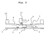
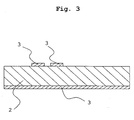
- a dielectric substrate 2 is formed from a composition containing the elastomer and the highly dielectric ceramic powder mixed therewith, and a conductive paste 6 is screen-printed on the dielectric substrate 2 to form an electrode 3.
- the above-described composition has the dielectric constant of not less than seven and the dielectric loss tangent of not more than 0.01.
- the electrode 3 at the ground side and at the radiant side is formed on the front and rear portions of the dielectric substrate 2.
- the dielectric antenna 1 is formed as a patch antenna.
- the conductive paste 6 is applied from the reverse of the screen 7 to the dielectric substrate 2 by a squeegee 11.
- the screen 7 is constructed of a shielding plate 8 on which a transmission portion 8a is selectively formed and a reticulate portion 9 disposed entirely on the lower surface of the shielding plate 8.
- the conductive paste 6 applied to the dielectric substrate 2 by the squeegee 11 permeates the transmission portion 8a of the shielding plate 8 and is printed selectively on the upper surface of the dielectric substrate 2 to form the electrode 3.
- a conductive material contained in the conductive paste to be used is not limited to a specific material so long as the conductive material is capable of holding conductivity to such an extent that the antenna performs its function.
- Au, Pt, Ag, Ni, and Sn can be used.
- Ag is especially preferable because it is excellent in the resistance to oxidation and the conductivity thereof.
- Ni is also especiallypreferable because it is inexpensive.
- the diameter of particles of the conductive material to be contained in the conductive paste is favorably 0.05 to 30 ⁇ m and more favorably 1 to 10 ⁇ m. It is difficult to treat fine particles whose diameter is less than 0.05 ⁇ m.
- the diameter of the fine particles is more than 30 ⁇ m because the thickness of the electrode is large and there is an increase in a necessary amount of the material to be used. It is unpreferable that the conductive paste is printed thickly because the thickness of a screen-printed layer is liable to be nonuniform and the volume resistivity changes.
- the mixing amount of the conductive material to be contained in the conductive paste is favorably 50 to 97 wt%.
- the mixing amount of a binder is 3 to 50 wt%.
- the mixing amount of the conductive material is more favorably 70 to 90 wt%.
- the remainder is the mixing amount of the binder. It is unpreferable that the mixing amount of the conductive material is less than 50 wt%, because the electrode is incapable of securing conductivity to such an extent that the electrode performs its function.
- the mixing amount of the conductive material is more than 97 wt% because the mixing amount of the binder is small and hence the electrode has a low degree of adhesion to the calcined material of the antenna and there is a possibility that the electrode cracks.
- the binder to be used is not limited to a specific kind, but the binder such as epoxy resin, butyral resin, polyester resin, and the like generally used can be used. Above all, epoxy-modified resin is especially preferable because it has favorable adhesion to the material of the antenna.
- the volume resistivity of the electrode is not limited to a specific value, provided that the volume resistivity thereof falls in a range in which the function of the antenna is not interfered. The volume resistivity of the electrode is favorably less than 10 -2 ⁇ cm.
- the volume resistivity of the electrode is more than 10 -2 ⁇ cm, because the conductivity of the electrode falls greatly and thereby the resonance frequency of the antenna shifts greatly and VSWR (voltage standing wave ratio) deteriorates.
- the volume resistivity of the electrode is more favorably less than 10 -3 ⁇ cm.
- the dielectric constant and dielectric loss tangent of the molding of the highly dielectric elastomer composition obtained in each example and comparison example and the temperature coefficient ⁇ of the dielectric constant of the molding thereof were measured by the following method.
- Test method 1 Measurement of dielectric constant and dielectric loss tangent at 25°C
- the molding obtained by molding the highly dielectric elastomer composition thermally and compressingly was processed into long and narrow specimens each having a dimension of 1.5 mm ⁇ 1.5 mm ⁇ 80 mm.
- a cavity resonator method pages 16 to 19 of magazine, "Electronic Monthly” published in July of 1998), the dielectric constant and dielectric loss tangent of each specimen were measured at 25°C in 1 GHz band.
- Test method 2 Measurement of dielectric constant at each temperature and temperature coefficient ⁇ of dielectric constant
- the molding of the highly dielectric elastomer composition was processed into specimens each having a predetermined configuration and a dimension of ⁇ 25 mm ⁇ t 1.5 mm.
- the dielectric constant at -40°C, 25°C, at 100°C and the temperature coefficient ⁇ of the dielectric constant were measured.
- a measuring apparatus used in the volumetric method was RF impedance/material analyzer HP4291B (produced by Agilent Technologies, Inc.).
- An electrode used was HP16453A (produced by Agilent Technologies, Inc.).
- EPDM ceramic powder of barium titanate ⁇ neodymium ("HF-120" produced by KCM Corporation Co., Ltd., dielectric constant: 120) in which the temperature coefficient ⁇ of the dielectric constant was -100 ⁇ 10 -6 , a vulcanization-accelerating agent, and a processing aid were mixed with one another at mixing ratios shown in table 1 to obtain a molding of each example having a dimension of 80 mm ⁇ 80 mm ⁇ 1.5 mm by thermal and compression molding.
- the vulcanizing condition was 170°C ⁇ 30 minutes in each example.
- the vulcanization-accelerating agent, the processing aid, and the like used were one part by weight (phr) of stearic acid ("LUNAC S-30” produced by Kao Corporation), five parts by weight (phr) of zinc oxide ("META-Z L-40" produced by INOUE CALCIUM CO., LTD.), three parts by weight (phr) of a processing aid ("SPLENDER R-100" produced by Kao Corporation), 2.5 parts by weight (phr) of a vulcanization-accelerating agent ("Soxinol M” produced by Sumitomo Chemical Co., Ltd.), and 1.5 parts by weight (phr) of sulfur (“GOLDEN FLOWER SULFUR POWDER” produced by Tsurumi Chemical Co., Ltd.).
- the dielectric constant and dielectric loss tangent of each of the obtained moldings were measured by the test method 1.
- the dielectric constant and the temperature coefficient ⁇ of the dielectric constant at each temperature were measured by the test method 2.
- Table 1 shows the results of the measurement.
- Moldings were obtained in the same condition and method as those of the example 1 except that the ceramic powder of the barium titanate ⁇ neodymium of the example 1 in which the temperature coefficient ⁇ of the dielectric constant was -100 ⁇ 10 -6 was replaced with the ceramic powder of the barium titanate ⁇ neodymium (HF-100 produced by KCM Corporation Co., Ltd., dielectric constant: 100) in which the temperature coefficient ⁇ of the dielectric constant was -40 ⁇ 10 -6 .
- Table 1 shows the results of the measurement.
- Table 1 Mixing amount Dielectric characteristic of molding EPDM Vulcanization-accelerating agent, Processing aid Ceramic powder Dielectric constant Dielectric loss tangent Dielectric constant Temperature coefficient of dielectric constant (25 to 100°C) Mixing amount Mixing amount Mixing amount Name of powder Dielectric constant Temperature coefficient of dielectric constant (Cavity resonator method: 1GHz) (Volumetric method: 1GHz) phr phr phr 25°C ⁇ 10 -6 /°C 25°C -40°C 25°C 100°C ⁇ 10 -6 /°C Example 1 100 13 400 HF-120 120 -100 10 0.002 10.9 10 9.1 -1200 2 100 13 800 HF-120 120 -100 16 0.002 17.5 16 14.6 -1200 3 100 13 1000 HF-120 120 -100 20 0.003 21.8 20 18.2 -1200 4 100 13 400 HF-100 100 -40 8 0.002 8.
- the dielectric constant of each molding at 25°C was not less than seven, the dielectric loss tangent thereof was not more than 0.01, and the temperature coefficient ⁇ of the dielectric constant thereof was -1200 ⁇ 10 -6 .
- the dielectric constant of each molding at 25°C was not less than seven, the dielectric loss tangent thereof was not more than 0.01, and the temperature coefficient of the dielectric constant thereof was -1067 ⁇ 10 -6 .
- the temperature coefficients ⁇ of the dielectric constant of the moldings were larger than -1500 ⁇ 10 -6 .
- the EPDM, ceramic powder of strontium titanate (ST-NAS" produced by KCM Corporation Co., Ltd., dielectric constant: 180) in which the temperature coefficient ⁇ of the dielectric constant was -1200 ⁇ 10 -6 , the vulcanization-accelerating agent, and the processing aid were mixed with one another at mixing ratios shown in table 2 to obtain moldings each having a dimension of 80 mm ⁇ 80 mm ⁇ 1.5 mm.
- the vulcanizing condition was 170°C ⁇ 30 minutes.
- the vulcanization-accelerating agent and the processing aid used were identical to those of the example 1.
- the dielectric constant and dielectric loss tangent of each of the obtained moldings were measured by the test method 1.
- the dielectric constant and the temperature coefficient ⁇ of the dielectric constant at each temperature were measured by the test method 2.
- Table 2 shows the results of the measurement.
- each comparison example was obtained in the same condition and method as those of the comparison example 1 except that the ceramic powder of the strontium titanate of the comparison example 1 in which the temperature coefficient ⁇ of the dielectric constant was -1200 ⁇ 10 -6 was replaced with ceramic powder of barium titanate powder (BT-32 produced by FUJI TITANIUM INDUSTRY CO., LTD., dielectric constant: 4000) in which the temperature coefficient ⁇ of the dielectric constant was -2000 ⁇ 10 -6 .
- BT-32 produced by FUJI TITANIUM INDUSTRY CO., LTD., dielectric constant: 4000
- the dielectric constant of eachmolding at 25°C was not less than seven, the dielectric loss tangent thereof was not more than 0.01, and the temperature coefficient ⁇ of the dielectric constant was -2667 ⁇ 10 -6 which was smaller than -1500 ⁇ 10 -6 .
- a shift generated when the molding is used as the material of an antenna cannot be kept within ⁇ 10% of the operating frequency.
- the dielectric constant of eachmolding at 25°C was not less than seven, the dielectric loss tangent thereof was more than 0.01, and the temperature coefficient ⁇ of the dielectric constant was -3333X 10 -6 which was smaller than -1500 ⁇ 10 -6 .
- a shift generated when the molding is used as the material of an antenna cannot be kept within ⁇ 10% of the operating frequency.
- Test method 3 (cavity resonator method) : Measurement of dielectric constant and dielectric loss tangent at 25°C
- test method 3 was carried out in a manner similar to that of the test method 1.
- the resonance frequency and the VSWR were measured by using a network analyzer.
- a gain in each resonance frequency was also measured in comparison with a reference antenna whose gain was known.
- Antennas satisfying the condition of VSWR ⁇ 2 and gain>2 dBi were marked by "good”. Antennas which did not satisfy this condition were marked by "poor".
- the ceramic powder of the barium titanate-neodymium ("HF-120" produced by KCM Corporation Co., Ltd., dielectric constant: 120) and small amount of additives including the vulcanization-accelerating agent and the processing aid were mixed with the EPDM at mixing ratios shown in table 3 to obtain a molding of each example having a dimension of 80 mm ⁇ 80 mm ⁇ 2 mm by thermal compression molding.
- the vulcanizing condition was 170°C ⁇ 30 minutes.
- the vulcanization-accelerating agent and the processing aid used were one part by weight (phr) of the stearic acid ("LUNAC S-30" produced by Kao Corporation), five parts by weight (phr) of the zinc oxide ("META-Z L-40" produced by INOUE CALCIUM CO., LTD.), three parts by weight (phr) of the processing aid ("SPLENDER R-100" produced by Kao Corporation), 2.5 parts by weight (phr) of the vulcanization-accelerating agent ("Soxinol M” produced by Sumitomo Chemical Co., Ltd.), and 1.5 parts by weight (phr) of the sulfur (“GOLDEN FLOWER SULFUR POWDER” produced by Tsurumi Chemical Co., Ltd.).
- a nickel-plated copper foil was bonded to both surfaces of each molding with an epoxy adhesive film (40 ⁇ m) by applying heat and pressure thereto to obtain a sheet of each example having a dimension of 60 mm ⁇ 60 mm ⁇ 2 mm.
- an antenna By using the material of an antenna, a patch antenna adapted to 2450 MHz was prepared.
- a power supply position and the configuration of the electrode of the antenna on the radiant surface thereof were selected according to the dielectric constant of the material of each antenna.
- An unnecessary portion was removed by etching. The etching was carried out by printing a resist of an electrode pattern and by using a solution of ferric chloride.
- Table 3 shows the kind of the electrode of each antenna, the deposit thickness, and the thickness of the copper foil.
- the property of each antenna was measured by the test method 4.
- Table 4 shows the results.
- the change in the property of each antenna was measured by the test method 5.
- Table 4 shows the results.
- Ag paste (“SILCOAT RF200" produced by FUKUDA METAL FOIL & POWDER CO., LTD.) was screen-printed on both surfaces of each molding in the same condition. After printing was conducted in a predetermined configuration on a surface of each of the moldings, they were dried at 80°C for 30 minutes. Thereafter the moldings were calcined at 150°C for 30 minutes. Table 3 shows the thickness of the electrode of each antenna and the volume resistivity thereof. The property of each antenna was measured by the test method 3. Table 4 shows the results. The change of the property of each antenna was measured by the test method 4. Table 4 shows the results.
- the ceramic powder of the strontium titanate (“ST-NAS” produced by KCM Corporation Co., Ltd., dielectric constant: 180) and small amount of additives including the vulcanization-accelerating agent and the processing aid were mixed with the EPDM at mixing ratios shown in table 3 to obtain a molding of each example having a dimension of 80 mm ⁇ 80 mm ⁇ 2 mm by carrying out thermal compression molding.
- the vulcanizing condition was 170°C ⁇ 30 minutes.
- the vulcanization-accelerating agent and the processing aid used were identical to those of the example 7.
- a silver-plated copper foil was bonded to both surfaces of each molding with an epoxy adhesive film (40 ⁇ m) by applying heat and pressure thereto to obtain a sheet of each example having a dimension of 60 mm ⁇ 60 mm ⁇ 2 mm.
- an antenna By using the material of an antenna, a patch antenna adapted to 2450 MHz was prepared.
- a power supply position and the configuration of the electrode of the antenna on the radiant surface thereof were selected according to the dielectric constant of the material of each antenna.
- An unnecessary portion was removed by etching. The etching was carried out by printing a resist of an electrode pattern and by using the solution of the ferric chloride.
- Table 3 shows the kind of the electrode of each antenna, the deposit thickness, and the thickness of the copper foil.
- the property of each antenna was measured by the test method 4.
- Table 4 shows the results.
- the change in the property of each antenna was measured by the test method 5.
- Table 4 shows the results.
- Ag paste (“SILCOAT RF200" produced by FUKUDA METAL FOIL & POWDER CO., LTD.) was screen-printed on both surfaces of the molding in the same condition. After printing was conducted in a predetermined configuration on a surface of each of the moldings, they were dried at 80°C for 30 minutes. Thereafter the moldings were calcined at 150°C for 30 minutes. Table 3 shows the thickness of the electrode of each antenna and the volume resistivity thereof. The property of each antenna was measured by the test method 3. Table 4 shows the results. The change in the property of each antenna was measured by the test method 5. Table 4 shows the results.
- the antennas of the examples 7 through 12 were judged as "good” before and after the aging test was conducted. Thus they can be used practicably.
- the ceramic powder of the barium titanate ⁇ neodymium ("HF-120" produced by KCM Corporation Co., Ltd., dielectric constant: 120) and small amount of additives including the vulcanization-accelerating agent and the processing aid were mixed with the EPDM at mixing ratios shown in table 5 to obtain a molding of each comparison example having a dimension of 80 mm ⁇ 80 mm ⁇ 2 mm by thermal compression molding.
- the vulcanizing condition was 170°C ⁇ 30 minutes.
- the vulcanization-accelerating agent and the processing aid used were identical to those of the example 7.
- An unplated copper foil was bonded to both surfaces of each molding with an epoxy adhesive film (40 ⁇ m) by applying heat and pressure thereto to obtain a sheet of each comparison example having a dimension of 60 mm ⁇ 60 mm ⁇ 2 mm.
- a patch antenna adapted to 2450 MHz was prepared.
- a power supplyposition and the configuration of the electrode of the antenna on the radiant surface thereof were selected according to the dielectric constant of the material of each antenna.
- An unnecessary portion was removed by etching. The etching was carried out by printing a resist of an electrode pattern and by using the solution of the ferric chloride.
- Table 5 shows the kind of the electrode of each antenna, and the thickness of the copper foil. The property of each antenna was measured by the test method 4. Table 6 shows the results. The change of the property of each antenna was measured by the test method 5. Table 6 shows the results.
- Table 5 BPDM Ceramic Vulcanisation-accelerating agent, Processing aid Dialectric characteristic of material of antenna (Cavity resonator method) Electrode-forming method Thickness copper foil Mixing Name amount phr Name of powder Mixing amount phr phr Dielectric constant Dielectric loss tangent ⁇ m Comparison Example 7 100 HF-120 400 13 10 0.002 Copper foil 35 8 100 BF-120 800 13 16 0.002 Copper foil 35 9 100 BF-120 1000 13 20 0.003 Copper foil 35 10 100 ST NAS 300 13 10 0.003 Copper plating - 11 100 ST NAS 600 13 20 0.004 Copper plating - 12 100 ST NAS 900 13 30 0.006 Copper plating - Table 6 Characteristic of antenna Judgement Characteristic of antenna after heat treatment at 100°C for 500 hours Judgement Resonance frequency VSWR Gain Resonance frequency VSNR Gain MHz dBi MHz dBi Comparison Example 7 2448 1.1 6 good 2435 2.6 1.9 poor 8 2445 1.2 5.8 good 2431
- the antennas of the comparison examples 7 through 12 were judged as "good” before the aging test was conducted, but after the aging test finished, VSWR>2 and gain ⁇ 2 dBi. Therefore they had inferior characteristics and unpreferable.
- the resulting highly dielectric elastomer composition can be preferably utilized as a composite material for electronic parts such as the antenna of a high-frequency communication apparatus which is dependent on temperature to a low extent.
- the electrode of the dielectric antenna is formed by bonding the plated copper foil to the molding of the highly dielectric elastomer composition or by bonding the conductive paste thereto by screen printing.
Abstract
Claims (12)
- Antenne diélectrique comprenant un moulage d'une composition élastomère fortement diélectrique et une électrode formée sur ledit moulage,
dans laquelle ladite composition élastomère fortement diélectrique comprend:un élastomère et une poudre céramique fortement diélectrique mélangée avec ledit élastomère,dans laquelle la poudre céramique fortement diélectrique possède un coefficient de température α (unité: 1/°C) d'une constante diélectrique de ladite poudre céramique sur un standard de 25°C variant de -200X10-8 à 100X10-6 sur un intervalle de température de -40°C à 100°C, le coefficient de température α de la constante diélectrique est une valeur définie par:dans laquelle (εr(t) et (εr(25) indiquent la constante diélectrique à une température donnée t dans l'intervalle de -40°C à 100°C et la constante diélectrique à 25°C respectivement.
- Antenne diélectrique selon la revendication 1, dans laquelle, à une fréquence de 1 GHz et une température de 25°C, ladite constante diélectrique de ladite composition élastomère fortement diélectrique n'est pas inférieure à sept et la tangente de perte diélectrique de celle-ci n'est pas supérieure à 0,01.
- Antenne diélectrique selon la revendication 1, dans laquelle ladite poudre céramique fortement diélectrique est une poudre céramique de titanate de baryum-néodyme.
- Antenne diélectrique selon la revendication 1, dans laquelle ledit élastomère contient une unité d'oléfine non polaire en tant qu'unité constituante de celui-ci.
- Antenne diélectrique selon la revendication 4, dans laquelle ledit élastomère est un caoutchouc d'éthylène et de propylène.
- Antenne diélectrique selon la revendication 1, qui est utilisée comme un matériau d'une partie électronique qui traite des signaux électriques ayant une fréquence qui n'est pas inférieure à 100 MHz.
- Antenne diélectrique selon la revendication 1, dans laquelle ladite composition élastomère fortement diélectrique comprend un élastomère et une poudre céramique fortement diélectrique mélangée avec ledit élastomère et, à une fréquence de 1 GHz et une température de 25°C, la constante diélectrique de ladite composition élastomère fortement diélectrique n'est pas inférieure à sept et la tangente de perte diélectrique de celle-ci n'est pas supérieure à 0,01.
- Antenne diélectrique selon la revendication 7, dans laquelle ladite électrode est composée d'une feuille de cuivre plaquée.
- Antenne diélectrique selon la revendication 8, dans laquelle ladite feuille de cuivre est plaquée avec du nickel ou de l'argent.
- Antenne diélectrique selon la revendication 7, dans laquelle ladite électrode est formée par une sérigraphie en utilisant une pâte conductrice.
- Antenne diélectrique selon la revendication 10, dans laquelle ladite pâte conductrice contient de 50 à 97% en poids d'une poudre conductrice et de 3 à 50% en poids d'un liant.
- Antenne diélectrique selon la revendication 7, qui est utilisée comme une partie électronique qui traite des signaux électriques ayant une fréquence qui n'est pas inférieure à 100 MHz.
Applications Claiming Priority (4)
| Application Number | Priority Date | Filing Date | Title |
|---|---|---|---|
| JP2004177969A JP4832729B2 (ja) | 2004-06-16 | 2004-06-16 | 高誘電性エラストマー組成物 |
| JP2004222910A JP2006042231A (ja) | 2004-07-30 | 2004-07-30 | 誘電体アンテナ |
| JP2004358623A JP2006164911A (ja) | 2004-12-10 | 2004-12-10 | 誘電体アンテナ |
| PCT/JP2005/010949 WO2005123841A1 (fr) | 2004-06-16 | 2005-06-15 | Composition élastomère fortement diélectrique et antenne diélectrique |
Publications (3)
| Publication Number | Publication Date |
|---|---|
| EP1767582A1 EP1767582A1 (fr) | 2007-03-28 |
| EP1767582A4 EP1767582A4 (fr) | 2009-12-30 |
| EP1767582B1 true EP1767582B1 (fr) | 2012-03-28 |
Family
ID=35509646
Family Applications (1)
| Application Number | Title | Priority Date | Filing Date |
|---|---|---|---|
| EP05751264A Expired - Fee Related EP1767582B1 (fr) | 2004-06-16 | 2005-06-15 | Composition élastomère fortement diélectrique et antenne diélectrique |
Country Status (3)
| Country | Link |
|---|---|
| US (1) | US7678853B2 (fr) |
| EP (1) | EP1767582B1 (fr) |
| WO (1) | WO2005123841A1 (fr) |
Cited By (2)
| Publication number | Priority date | Publication date | Assignee | Title |
|---|---|---|---|---|
| WO2015000057A1 (fr) * | 2013-07-03 | 2015-01-08 | University Of Saskatchewan | Matériaux composites pour applications microondes à base de diélectrique |
| US10784583B2 (en) | 2013-12-20 | 2020-09-22 | University Of Saskatchewan | Dielectric resonator antenna arrays |
Families Citing this family (12)
| Publication number | Priority date | Publication date | Assignee | Title |
|---|---|---|---|---|
| JP2006311372A (ja) * | 2005-04-28 | 2006-11-09 | Hitachi Ltd | 無線icタグ |
| JP2008239946A (ja) | 2007-02-28 | 2008-10-09 | Ntn Corp | 誘電性エラストマー組成物およびアンテナ用部材 |
| JP5362205B2 (ja) | 2007-04-24 | 2013-12-11 | Ntn株式会社 | 高周波用電子部品材料 |
| WO2008133130A1 (fr) * | 2007-04-24 | 2008-11-06 | Ntn Corporation | Corps moulé à base d'élastomère hautement diélectrique et matériau de composant électronique utilisable à haute fréquence |
| US8357314B2 (en) * | 2007-09-28 | 2013-01-22 | Ntn Corporation | Dielectric elastomer composition and high-frequency electronic component material |
| US7719164B2 (en) | 2008-08-06 | 2010-05-18 | Honeywell International Inc. | Patterned dielectric elastomer actuator and method of fabricating the same |
| US9122967B2 (en) * | 2010-04-14 | 2015-09-01 | Technologies Roi, Llc | Radio frequency identification tags and methods employing ceramic components, which may be suitable for use in extreme environmental conditions |
| CN101899177B (zh) * | 2010-07-09 | 2011-08-10 | 北京化工大学 | 一种高介电常数低模量介电弹性体材料及其制备方法 |
| JP5307092B2 (ja) * | 2010-08-18 | 2013-10-02 | シャープ株式会社 | アンテナ装置およびそれを備える電気機器 |
| EP2737575B1 (fr) | 2011-07-29 | 2024-05-01 | University of Saskatchewan | Antennes à résonateur à base de polymère |
| US9937526B2 (en) * | 2011-09-30 | 2018-04-10 | Apple Inc. | Antenna structures with molded and coated substrates |
| EP2951885B1 (fr) * | 2013-01-31 | 2020-01-15 | University of Saskatchewan | Antennes à résonateur à base de méta-matériaux |
Family Cites Families (16)
| Publication number | Priority date | Publication date | Assignee | Title |
|---|---|---|---|---|
| JPS6041633B2 (ja) * | 1980-03-25 | 1985-09-18 | 松下電器産業株式会社 | 誘電体共振器用磁器材料 |
| JPS57115704A (en) * | 1981-01-12 | 1982-07-19 | Matsushita Electric Ind Co Ltd | Temperature compensating dielectric porcelain composition |
| JPS59191204A (ja) * | 1983-04-15 | 1984-10-30 | 松下電器産業株式会社 | 誘電体磁器組成物 |
| JPS63259904A (ja) * | 1987-04-17 | 1988-10-27 | 日本特殊陶業株式会社 | 複合誘電体 |
| US5677029A (en) * | 1990-11-19 | 1997-10-14 | Alliedsignal Inc. | Ballistic resistant fabric articles |
| JPH0629727A (ja) | 1992-05-21 | 1994-02-04 | Ngk Insulators Ltd | スロットアンテナおよびその製造方法 |
| JP2830743B2 (ja) | 1993-06-17 | 1998-12-02 | 三菱電機株式会社 | シールドループアンテナ |
| JP3485391B2 (ja) | 1995-07-20 | 2004-01-13 | 大塚化学ホールディングス株式会社 | 高誘電性エラストマー組成物及びそれを用いた電子材料 |
| US5962122A (en) * | 1995-11-28 | 1999-10-05 | Hoechst Celanese Corporation | Liquid crystalline polymer composites having high dielectric constant |
| JP4505904B2 (ja) | 1999-11-18 | 2010-07-21 | 株式会社村田製作所 | 誘電体アンテナの製造方法 |
| CN1256735C (zh) * | 2000-04-26 | 2006-05-17 | 古河电气工业株式会社 | 介电陶瓷、树脂-陶瓷复合材料、电气部件和天线及其制造方法 |
| JP2003078322A (ja) | 2001-08-30 | 2003-03-14 | Hitachi Cable Ltd | 携帯電話機用内蔵アンテナ及び携帯電話機 |
| JP4127995B2 (ja) | 2001-10-22 | 2008-07-30 | Tdk株式会社 | 複合誘電体材料および基板 |
| JP3973877B2 (ja) * | 2001-10-31 | 2007-09-12 | 株式会社フジクラ | 高誘電率ゴム組成物 |
| JP4268371B2 (ja) | 2002-05-28 | 2009-05-27 | パナソニック電工株式会社 | 熱可塑性樹脂組成物及び成形品 |
| JP2004059702A (ja) | 2002-07-26 | 2004-02-26 | Matsushita Electric Works Ltd | 高周波用熱可塑性樹脂組成物及び成形品 |
-
2005
- 2005-06-15 WO PCT/JP2005/010949 patent/WO2005123841A1/fr active Application Filing
- 2005-06-15 US US11/629,646 patent/US7678853B2/en not_active Expired - Fee Related
- 2005-06-15 EP EP05751264A patent/EP1767582B1/fr not_active Expired - Fee Related
Cited By (2)
| Publication number | Priority date | Publication date | Assignee | Title |
|---|---|---|---|---|
| WO2015000057A1 (fr) * | 2013-07-03 | 2015-01-08 | University Of Saskatchewan | Matériaux composites pour applications microondes à base de diélectrique |
| US10784583B2 (en) | 2013-12-20 | 2020-09-22 | University Of Saskatchewan | Dielectric resonator antenna arrays |
Also Published As
| Publication number | Publication date |
|---|---|
| EP1767582A1 (fr) | 2007-03-28 |
| WO2005123841A1 (fr) | 2005-12-29 |
| US20070182640A1 (en) | 2007-08-09 |
| US7678853B2 (en) | 2010-03-16 |
| EP1767582A4 (fr) | 2009-12-30 |
Similar Documents
| Publication | Publication Date | Title |
|---|---|---|
| EP1767582B1 (fr) | Composition élastomère fortement diélectrique et antenne diélectrique | |
| EP1720217B1 (fr) | Antenne dielectrique | |
| EP1324388B1 (fr) | Méthode de refroidissement pour des composants électroniques et pellicule thermiquement conductrice associée | |
| US20230344116A1 (en) | Polymer Composition for Use in an Antenna System | |
| KR100674848B1 (ko) | 고유전율 금속-세라믹-폴리머 복합 유전체 및 이를 이용한임베디드 커패시터의 제조 방법 | |
| CN1969016A (zh) | 高介电性弹性体组合物及电介体天线 | |
| EP2775589A1 (fr) | Feuille d'émission, unité d'émission et système d'émission d'énergie électrique sans contact comportant celle-ci | |
| CN114364521A (zh) | 用于激光直接结构化的聚合物组合物 | |
| KR20010013831A (ko) | 유전성 복합 재료 조성물, 및 이로부터 제조한 필름,기판, 전자 부품 및 성형 제품 | |
| WO2010038772A1 (fr) | Etiquette rf et procédé de fabrication de cette étiquette rf | |
| US20130234912A1 (en) | Antenna apparatus | |
| EP3595004B1 (fr) | Composition thermoconductrice | |
| JPH11274843A (ja) | アンテナ装置 | |
| JP2873541B2 (ja) | 高周波通信機のアンテナ基板材料成形用樹脂組成物 | |
| JP2007043236A (ja) | 誘電体アンテナ | |
| US6442399B1 (en) | Mobile communication apparatus | |
| EP0732712B1 (fr) | Diélectrique pour condensateur et méthode de fabrication | |
| WO2005023916A2 (fr) | Pate absorbant les micro-ondes mise en forme sur place | |
| JP2006164911A (ja) | 誘電体アンテナ | |
| JP4496858B2 (ja) | 電子部品及び多層基板 | |
| KR102383379B1 (ko) | 전도성 실리콘 페이스트 및 이로부터 제조된 전자파 차폐 가스켓 | |
| JP2006042231A (ja) | 誘電体アンテナ | |
| KR102018157B1 (ko) | 전자파 차폐필름, 이를 포함하는 인쇄 회로 기판 및 이의 제조방법 | |
| CN113773615B (zh) | 用于天线振子的塑料 | |
| JPH07162111A (ja) | 複合誘電体基板 |
Legal Events
| Date | Code | Title | Description |
|---|---|---|---|
| PUAI | Public reference made under article 153(3) epc to a published international application that has entered the european phase |
Free format text: ORIGINAL CODE: 0009012 |
|
| 17P | Request for examination filed |
Effective date: 20070105 |
|
| AK | Designated contracting states |
Kind code of ref document: A1 Designated state(s): DE FR |
|
| RBV | Designated contracting states (corrected) |
Designated state(s): DE FR |
|
| DAX | Request for extension of the european patent (deleted) | ||
| A4 | Supplementary search report drawn up and despatched |
Effective date: 20091127 |
|
| RIC1 | Information provided on ipc code assigned before grant |
Ipc: C08L 21/00 20060101ALI20091120BHEP Ipc: C08L 101/12 20060101ALI20091120BHEP Ipc: H01Q 1/38 20060101ALI20091120BHEP Ipc: H01B 3/12 20060101ALI20091120BHEP Ipc: H01B 3/00 20060101ALI20091120BHEP Ipc: C08L 23/16 20060101ALI20091120BHEP Ipc: C08K 3/00 20060101ALI20091120BHEP Ipc: C08L 101/00 20060101AFI20060109BHEP |
|
| 17Q | First examination report despatched |
Effective date: 20100429 |
|
| REG | Reference to a national code |
Ref country code: DE Ref legal event code: R079 Ref document number: 602005033393 Country of ref document: DE Free format text: PREVIOUS MAIN CLASS: C08L0101000000 Ipc: C08L0101120000 |
|
| GRAP | Despatch of communication of intention to grant a patent |
Free format text: ORIGINAL CODE: EPIDOSNIGR1 |
|
| RIC1 | Information provided on ipc code assigned before grant |
Ipc: C08L 21/00 20060101ALN20110921BHEP Ipc: H01Q 9/04 20060101ALI20110921BHEP Ipc: C08K 3/22 20060101ALI20110921BHEP Ipc: C08L 101/12 20060101AFI20110921BHEP |
|
| RIC1 | Information provided on ipc code assigned before grant |
Ipc: C08L 21/00 20060101ALI20110929BHEP Ipc: H01Q 9/04 20060101ALI20110929BHEP Ipc: C08K 3/22 20060101ALI20110929BHEP Ipc: C08L 101/12 20060101AFI20110929BHEP |
|
| GRAS | Grant fee paid |
Free format text: ORIGINAL CODE: EPIDOSNIGR3 |
|
| GRAA | (expected) grant |
Free format text: ORIGINAL CODE: 0009210 |
|
| AK | Designated contracting states |
Kind code of ref document: B1 Designated state(s): DE FR |
|
| REG | Reference to a national code |
Ref country code: DE Ref legal event code: R096 Ref document number: 602005033393 Country of ref document: DE Effective date: 20120524 |
|
| PGFP | Annual fee paid to national office [announced via postgrant information from national office to epo] |
Ref country code: DE Payment date: 20120613 Year of fee payment: 8 |
|
| PGFP | Annual fee paid to national office [announced via postgrant information from national office to epo] |
Ref country code: FR Payment date: 20120619 Year of fee payment: 8 |
|
| PLBE | No opposition filed within time limit |
Free format text: ORIGINAL CODE: 0009261 |
|
| STAA | Information on the status of an ep patent application or granted ep patent |
Free format text: STATUS: NO OPPOSITION FILED WITHIN TIME LIMIT |
|
| 26N | No opposition filed |
Effective date: 20130103 |
|
| REG | Reference to a national code |
Ref country code: DE Ref legal event code: R097 Ref document number: 602005033393 Country of ref document: DE Effective date: 20130103 |
|
| REG | Reference to a national code |
Ref country code: DE Ref legal event code: R119 Ref document number: 602005033393 Country of ref document: DE Effective date: 20140101 |
|
| REG | Reference to a national code |
Ref country code: FR Ref legal event code: ST Effective date: 20140228 |
|
| PG25 | Lapsed in a contracting state [announced via postgrant information from national office to epo] |
Ref country code: DE Free format text: LAPSE BECAUSE OF NON-PAYMENT OF DUE FEES Effective date: 20140101 |
|
| PG25 | Lapsed in a contracting state [announced via postgrant information from national office to epo] |
Ref country code: FR Free format text: LAPSE BECAUSE OF NON-PAYMENT OF DUE FEES Effective date: 20130701 |