EP1764558A2 - Schließvorrichtung für eine Tür eines Haushaltsgeräts - Google Patents
Schließvorrichtung für eine Tür eines Haushaltsgeräts Download PDFInfo
- Publication number
- EP1764558A2 EP1764558A2 EP06120544A EP06120544A EP1764558A2 EP 1764558 A2 EP1764558 A2 EP 1764558A2 EP 06120544 A EP06120544 A EP 06120544A EP 06120544 A EP06120544 A EP 06120544A EP 1764558 A2 EP1764558 A2 EP 1764558A2
- Authority
- EP
- European Patent Office
- Prior art keywords
- door
- movement
- damping
- closing
- household appliance
- Prior art date
- Legal status (The legal status is an assumption and is not a legal conclusion. Google has not performed a legal analysis and makes no representation as to the accuracy of the status listed.)
- Granted
Links
Images


Classifications
-
- F—MECHANICAL ENGINEERING; LIGHTING; HEATING; WEAPONS; BLASTING
- F24—HEATING; RANGES; VENTILATING
- F24C—DOMESTIC STOVES OR RANGES ; DETAILS OF DOMESTIC STOVES OR RANGES, OF GENERAL APPLICATION
- F24C15/00—Details
- F24C15/02—Doors specially adapted for stoves or ranges
- F24C15/023—Mounting of doors, e.g. hinges, counterbalancing
-
- E—FIXED CONSTRUCTIONS
- E05—LOCKS; KEYS; WINDOW OR DOOR FITTINGS; SAFES
- E05F—DEVICES FOR MOVING WINGS INTO OPEN OR CLOSED POSITION; CHECKS FOR WINGS; WING FITTINGS NOT OTHERWISE PROVIDED FOR, CONCERNED WITH THE FUNCTIONING OF THE WING
- E05F5/00—Braking devices, e.g. checks; Stops; Buffers
- E05F5/02—Braking devices, e.g. checks; Stops; Buffers specially for preventing the slamming of swinging wings during final closing movement, e.g. jamb stops
- E05F5/027—Braking devices, e.g. checks; Stops; Buffers specially for preventing the slamming of swinging wings during final closing movement, e.g. jamb stops with closing action
-
- F—MECHANICAL ENGINEERING; LIGHTING; HEATING; WEAPONS; BLASTING
- F24—HEATING; RANGES; VENTILATING
- F24C—DOMESTIC STOVES OR RANGES ; DETAILS OF DOMESTIC STOVES OR RANGES, OF GENERAL APPLICATION
- F24C15/00—Details
- F24C15/02—Doors specially adapted for stoves or ranges
- F24C15/026—Doors specially adapted for stoves or ranges stowing of door in open position
-
- E—FIXED CONSTRUCTIONS
- E05—LOCKS; KEYS; WINDOW OR DOOR FITTINGS; SAFES
- E05Y—INDEXING SCHEME ASSOCIATED WITH SUBCLASSES E05D AND E05F, RELATING TO CONSTRUCTION ELEMENTS, ELECTRIC CONTROL, POWER SUPPLY, POWER SIGNAL OR TRANSMISSION, USER INTERFACES, MOUNTING OR COUPLING, DETAILS, ACCESSORIES, AUXILIARY OPERATIONS NOT OTHERWISE PROVIDED FOR, APPLICATION THEREOF
- E05Y2201/00—Constructional elements; Accessories therefor
- E05Y2201/40—Motors; Magnets; Springs; Weights; Accessories therefor
- E05Y2201/404—Function thereof
- E05Y2201/416—Function thereof for counterbalancing
-
- E—FIXED CONSTRUCTIONS
- E05—LOCKS; KEYS; WINDOW OR DOOR FITTINGS; SAFES
- E05Y—INDEXING SCHEME ASSOCIATED WITH SUBCLASSES E05D AND E05F, RELATING TO CONSTRUCTION ELEMENTS, ELECTRIC CONTROL, POWER SUPPLY, POWER SIGNAL OR TRANSMISSION, USER INTERFACES, MOUNTING OR COUPLING, DETAILS, ACCESSORIES, AUXILIARY OPERATIONS NOT OTHERWISE PROVIDED FOR, APPLICATION THEREOF
- E05Y2900/00—Application of doors, windows, wings or fittings thereof
- E05Y2900/30—Application of doors, windows, wings or fittings thereof for domestic appliances
- E05Y2900/308—Application of doors, windows, wings or fittings thereof for domestic appliances for ovens
-
- F—MECHANICAL ENGINEERING; LIGHTING; HEATING; WEAPONS; BLASTING
- F24—HEATING; RANGES; VENTILATING
- F24C—DOMESTIC STOVES OR RANGES ; DETAILS OF DOMESTIC STOVES OR RANGES, OF GENERAL APPLICATION
- F24C15/00—Details
- F24C15/18—Arrangement of compartments additional to cooking compartments, e.g. for warming or for storing utensils or fuel containers; Arrangement of additional heating or cooking apparatus, e.g. grills
Definitions
- the invention is based on a closing device for a first element of a household appliance designed as a door according to the preamble of claim 1.
- the invention is based on a closure device for a first element of a domestic appliance designed as a door, with closing means for actively moving the door to a second element and a damping means arranged on the same element as the closing means with an energy dissipation element for damping the movement of the door.
- the damping means damps the movement of the door to the second element at least predominantly in a damping region arranged shortly before a closed position.
- the door can be braked softly shortly before its closed position, without an operator having to press against a strong damping of a damping element during the entire closing movement.
- An operator can close the door with almost any force or speed, the door always being soft in its closed position by the damping means in combination with the closing means is moved.
- the energy dissipation element can in this case act pneumatically or hydraulically.
- the damping energy absorption of the energy dissipation element is expediently dependent on the closing speed of the door.
- a spring-back of the door from the closed position can be effectively prevented if the Energydissipationselement is powerless at a door arranged in the closed position. Without a movement of the door, the Energydissipationselement is expediently powerless.
- the closing means can apply a force on the door, for example, pull on the door or press on the door.
- the damping means is arranged on the same element as the moving means, so it can be arranged on the door or on the element to which the door is moved, such as the rest of the body of the household appliance.
- the damping range can range from the closed position to a distance of 30 ° before the closed position, in particular 20 ° before the closed position.
- the damping area advantageously extends from the closed position to 15 cm, in particular only up to 10 cm, before the closed position.
- the damping means dampens the movement of the door to the second element exclusively in the damping region.
- the door outside the damping range can be moved very easily and without a large force resistance.
- a compact and easy-to-mount moving device can be provided when the damping means and the moving means are combined in one element.
- a good balance between a damping force and a force of movement can be achieved on the door.
- the closing means causes the movement of the first element to the second element at least predominantly in a movement region arranged shortly before the closed position.
- a good interaction between damping and active movement of the door can be achieved, in particular if the movement range and the damping range are identical.
- the door outside the range of motion of a movement of the closing means is independent movable, whereby a combination of the damping means with the closing means can be achieved particularly easily.
- a simple and reliable coupling of the door to the closing means can be achieved if the closing means has a first stable position in which it rests when the door is arranged outside the movement range. Expediently, between the stable position and the movement region, a potential peak to be overcome by the closing means is arranged, which can be overcome by a rotational movement of the closing means. In this way, the closing means can be reliably maintained in the first stable position in a simple manner until the door is coupled to the closing means.
- the invention is particularly advantageously applicable to a door which, when moved to the second element, undergoes a translational trajectory, e.g. with a door on a baking cart or a retractable in the household appliance door.
- a particularly simple installation of the closing means and the damping means can be achieved by a housing which surrounds and carries the closing means, the damping means and a holding means for holding an element of the door.
- the housing expediently has an opening to the inlet of a holding element of the door for moving the door.
- the movement device can be coupled in a simple manner with the door for moving the door.
- the invention is also based on a household appliance with a device housing, a door, a closing means for actively closing the door, a damping means for damping the movement of the door and a holding means for holding an element of the door. It is proposed that the closing means, the damping means and the retaining means are surrounded by a housing within the device housing. As a result, a simple assembly of the closing means and the damping means can be achieved. This is especially true when the closing means and the damping means are attached to the housing.
- a space-saving housing of the housing can be achieved if the housing is mounted below a slot connected to the door.
- a cost-saving and modular construction of home appliances can be achieved by a system with at least a first and a second household appliance as described above are achieved, wherein the housing of the first household appliance is attached to a different location within the household appliance than the housing of the second household appliance. In particular, both cases are identical, whereby the manufacturing cost of the housing or the entire movement device with the closing means and the damping means can be kept low.
- the modular design can be made particularly effective when the housing of the first household appliance under a slot connected to a door - for example, in a stove with a baking tray - and the housing of the second household appliance side of a door - for example, in a stove with a retractable door - is attached.
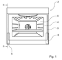
- FIG 1 shows a front view of a schematically illustrated household appliance 2, which is designed as a stove.
- the stove has a door 4, which is shown in the figure in its closed position and which limits a cooking chamber 6 located behind it.
- the door 4 is connected to two closing devices 8 for closing the door 4.
- the closing devices 8 are arranged within a device housing 9 of the household appliance 2.
- FIG. 1 A sectional side view through one of the closing devices 8 and laterally on the door 4 is shown in FIG.
- the door 4 is pivotally mounted about two pivot axes 10, 12, wherein the first pivot axis 10 extends through a fastened in the hull of the household appliance 2 bolt 14. This pivot axis 10 is therefore stationary in the household appliance 2.
- the second pivot axis 12 is movably mounted with the door 4 in a bolt 18 in a rail 16 and moves when opening and closing the door 4 with the door 4 in a holding element 20 to the rear, as shown in Figure 3, or forward within a housing 22 of the locking device eighth
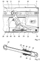
- FIG. 4 shows a side view into the closing device 8 with the holding element 20, the pivot axis 12 arranged therein, a damping and closing means 24 and a gripping arm 26 connected to the damping and closing means 24.
- the damping and closing means 24 is shown in FIG a sectional view shown. It comprises a closing means 28 with a compression spring 30, which is wound around a piston 32 and pushes it into a chamber 34.
- the chamber 34 together with a damping ring 36 is part of a damping means 38 for damping the movement of the door 4.
- the damping ring 36 and the chamber 34 thus together form an energy dissipation element.
- a compensation opening 40 ensures a constant air pressure in the region of the compression spring 30.
- the damping and closing means 24 is connected with its piston 32 at a mounting opening 42 by a screw 44 with the gripping arm 26, wherein the piston 32 is rotatably mounted relative to the gripping arm 26 about a pivot axis 46.
- the gripper arm 26 is rotatably mounted about a pivot axis 48 relative to the housing 22.
- the Damping and closing means 24 in turn is rotatably mounted about a further pivot axis 50.
- the holding member 20 In the open position of the door 4, the holding member 20 is in the position shown in Figure 3 in the rear region of the household appliance 2.
- the door 4 is first raised by an operator on a handle 52, wherein the door 4 fastened retaining element 20 in the rail 16 slides forward.
- the gripping arm 26 rests in this case - pressed against a stop 58 - in a stable waiting position shown in FIGS. 4 and 6 until the holding element 20 has slid so far forward in the rail 16 that it has the position shown in FIGS. 4 and 6 reached.
- a projection 54 of the holding member 20 is inserted into a recess 56 of the gripping arm 26.
- the projection 54 presses on the gripper arm 26 and pivots it about the pivot axis 48 in a clockwise direction.
- the connected to the gripping arm 26 piston 32 is thereby pulled up, whereby the compression spring 30 is pressed a small piece against its direction of pressure.
- the holding means 20 forward of the gripping arm 26 is pressed further to the right and the projection 54 presses further into the recess 56 into it.
- the compression spring 30 is moved beyond its tense point and can now relax again, the piston 32 is pulled into the chamber 34 and thus the gripping arm 26 to the right and thus forward.
- the projection 54 which is securely mounted in the recess 56 is thus likewise pulled forward and with it the retaining element 20 which presses the door 4 into its closed position shown in FIG. In this closed position, the projection 54, as shown in Figure 7, completely in the recess 56.
- the door 4 passes through during its closing movement a curved translational trajectory toward its closed position.
- the closing means 28 must first overcome a small potential mountain during its movement from its stable position shown in FIGS. 4 and 6 until, in a subsequent movement region, it can pull the holding means 20 forward and thus the door 4 in the direction of its closed position.
- the holding member 20 is moved about 15 cm within the rail 16, as shown in Figure 4.
- the damping means 38 also comes into action, since within the range of movement of the piston 32 is pulled into the chamber 34 and thereby the damping ring 36 is moved. In this way, a soft, soft pulling the door 4 is achieved in its closed position.
- the damping means 38 damps the movement of the door 4 hereby exclusively in a shortly before the closed position of the door 4 arranged damping region which is identical to the movement range of the closing means 28th
- the locking device 8 with its housing 22, which surrounds the closing means 28, the damping means 38 and the holding means for holding an element of the door 4 gripping arm 26 and carries, by fastening means 60 laterally to a Device housing 62 of the household appliance 2, for example, an inner housing of the household appliance 2 attached.
- the housing 22 in this case has an opening 64 which serves for the inlet of the holding element 20 and forms the rail 16 at its edges.
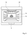
- FIG. 8 shows another household appliance 68 with an insert 70 designed as a baking carriage, which is rigidly connected to a door 72 of the domestic appliance 68.
- a closing device 8 is arranged, which is identical to the two closing devices 8 shown in FIGS. 1 to 7.
- an unillustrated holding element of the door 72 and the drawer 70 whereby the door 72 and the drawer 70 are moved in their closed position by a damping and closing means upon closing movement after reaching a movement range.
- the household appliances 2 and 68 are designed so that the locking devices 8 can be modularly attached to one or the other household appliance 2, 68 without having to be adapted for this purpose.
Landscapes
- Engineering & Computer Science (AREA)
- Chemical & Material Sciences (AREA)
- Combustion & Propulsion (AREA)
- Mechanical Engineering (AREA)
- General Engineering & Computer Science (AREA)
- Electric Ovens (AREA)
- Drawers Of Furniture (AREA)
- Fluid-Damping Devices (AREA)
Abstract
Description
- Die Erfindung geht aus von einer Schließvorrichtung für ein als Tür ausgeführtes erstes Element eines Haushaltsgeräts nach dem Oberbegriff des Anspruchs 1.
- Aus der
EP 0 478 523 A1 ist eine Tür für eine Geschirrspülmaschine bekannt, die durch ein Federelement in eine Schließposition gezogen wird. Um ein unerwünschtes Herunterfallen der Tür entgegen der Federkraft des Federelements auf einen Öffnungsanschlag zu verhindern, wird die Tür zusätzlich durch einen Dämpfer gehalten, der die Öffnungsbewegung der Tür dämpft. - Es ist die Aufgabe der vorliegenden Erfindung, eine Schließvorrichtung für eine Tür eines Haushaltsgeräts anzugeben, die insbesondere hinsichtlich ihrer Handhabbarkeit verbessert ist.
- Diese Aufgabe wird erfindungsgemäß durch die Merkmale des Patentanspruchs 1 gelöst. Vorteilhafte Ausgestaltungen und Weiterbildungen der Erfindung können den Unteransprüchen entnommen werden.
- Die Erfindung geht aus von einer Schließvorrichtung für ein als Tür ausgeführtes erstes Element eines Haushaltsgeräts, mit einem Schließmittel zur aktiven Bewegung der Tür zu einem zweiten Element und einem an dem gleichen Element wie das Schließmittel angeordneten Dämpfungsmittel mit einem Energiedissipationselement zum Dämpfen der Bewegung der Tür.
- Es wird vorgeschlagen, dass das Dämpfungsmittel die Bewegung der Tür zum zweiten Element zumindest vorwiegend in einem kurz vor einer Schließstellung angeordneten Dämpfungsbereich dämpft. Die Tür kann kurz vor ihrer Schließstellung weich abgebremst werden, ohne dass ein Bediener während der gesamten Schließbewegung gegen eine starke Dämpfung eines Dämpfungselements andrücken muss. Ein Bediener kann die Tür mit nahezu beliebiger Kraft oder Geschwindigkeit schließen, wobei die Tür durch das Dämpfungsmittel im Verbund mit dem Schließmittel stets weich in ihre Schließstellung bewegt wird. Durch die Verwendung eines Energiedissipationselements kann die von der Bewegung der Tür aufgenommene Energie vollständig in Wärme umgewandelt werden, wodurch einem ungewollten Zurückspringen der Tür aus der Endstellung entgegengewirkt wird. Das Energiedissipationselement kann hierbei pneumatisch oder hydraulisch wirken. Die Dämpfungsenergieaufnahme des Energiedissipationselements ist zweckmäßigerweise abhängig von der Schließgeschwindigkeit der Tür. Ein Zurückfedern der Tür aus der Schließstellung kann wirksam verhindert werden, wenn das Energiedissipationselement bei einer in Schließstellung angeordneten Tür kraftlos ist. Ohne eine Bewegung der Tür ist das Energiedissipationselement zweckmäßigerweise kraftlos. Durch die aktive Bewegung kann das Schließmittel eine Kraft auf die Tür aufbringen, beispielsweise an der Tür ziehen oder an der Tür drücken. Das Dämpfungsmittel ist am gleichen Element wie das Bewegungsmittel angeordnet, kann also an der Tür oder an dem Element, auf das die Tür zu bewegt wird, wie beispielsweise der restliche Korpus des Haushaltsgeräts, angeordnet sein. Der Dämpfungsbereich kann von der Schließstellung bis zu einer Entfernung von 30° vor der Schließstellung, insbesondere 20° vor der Schließstellung, reichen. Bei translatorisch bewegbaren Türen reicht der Dämpfungsbereich vorteilhafterweise von der Schließstellung bis 15 cm, insbesondere nur bis 10 cm vor die Schließstellung.
- In einer vorteilhaften Ausgestaltung der Erfindung dämpft das Dämpfungsmittel die Bewegung der Tür zum zweiten Element ausschließlich im Dämpfungsbereich. Hierdurch kann die Tür außerhalb des Dämpfungsbereichs sehr leicht und ohne einen großen Kraftwiderstand bewegt werden.
- Eine kompakte und leicht zu montierende Bewegungsvorrichtung kann geschaffen werden, wenn das Dämpfungsmittel und das Bewegungsmittel in einem Element zusammengefasst sind. Außerdem kann eine gute Abstimmung zwischen einer Dämpfungskraft und einer Bewegungskraft auf die Tür erzielt werden.
- Vorteilhafterweise veranlasst das Schließmittel die Bewegung des ersten Elements zum zweiten Element zumindest vorwiegend in einem kurz vor der Schließstellung angeordneten Bewegungsbereich. Hierdurch kann ein gutes Zusammenwirken zwischen Dämpfung und aktiver Bewegung der Tür erreicht werden, insbesondere, wenn der Bewegungsbereich und der Dämpfungsbereich identisch sind. Zweckmäßigerweise ist hierbei die Tür außerhalb des Bewegungsbereichs von einer Bewegung des Schließmittels unabhängig bewegbar, wodurch eine Kombination des Dämpfungsmittels mit dem Schließmittel besonders einfach erreicht werden kann.
- Ein einfaches und zuverlässiges Ankoppeln der Tür an das Schließmittel kann erreicht werden, wenn das Schließmittel eine erste stabile Stellung aufweist, in der es bei außerhalb des Bewegungsbereichs angeordneter Tür ruht. Zweckmäßigerweise ist zwischen der stabilen Stellung und dem Bewegungsbereich ein von dem Schließmittel zu überwindender Potentialberg angeordnet, der durch eine rotatorische Bewegung des Schließmittels überwindbar ist. Hierdurch kann das Schließmittel auf einfache Weise zuverlässig in der ersten stabilen Stellung gehalten bleiben, bis die Tür am Schließmittel ankoppelt.
- Die Erfindung ist besonders vorteilhaft anwendbar bei einer Tür, die bei einer Bewegung zum zweiten Element eine translatorische Bewegungsbahn durchläuft, wie z.B. bei einer Tür an einem Backwagen oder einer im Haushaltsgerät versenkbaren Tür.
- Eine besonders einfache Montage des Schließmittels und des Dämpfungsmittels kann durch ein Gehäuse erreicht werden, das das Schließmittel, das Dämpfungsmittel und ein Haltemittel zum Halten eines Elements der Tür umgreift und trägt. Hierbei hat das Gehäuse zweckmäßigerweise eine Öffnung zum Einlass eines Halteelements der Tür zum Bewegen der Tür. Hierdurch kann die Bewegungsvorrichtung in einfacher Weise mit der Tür zum Bewegen der Tür gekoppelt werden.
- Die Erfindung geht außerdem aus von einem Haushaltsgerät mit einem Gerätegehäuse, einer Tür, einem Schließmittel zum aktiven Schließen der Tür, einem Dämpfungsmittel zum Dämpfen der Bewegung der Tür und einem Haltemittel zum Halten eines Elements der Tür. Es wird vorgeschlagen, dass das Schließmittel, das Dämpfungsmittel und das Haltemittel von einem Gehäuse innerhalb des Gerätegehäuses umgeben sind. Hierdurch kann eine einfache Montage des Schließmittels und des Dämpfungsmittels erreicht werden. Dies gilt insbesondere, wenn das Schließmittel und das Dämpfungsmittel am Gehäuse befestigt sind.
- Eine Platz sparende Unterbringung des Gehäuses kann erreicht werden, wenn das Gehäuse unterhalb eines mit der Tür verbundenen Einschubs befestigt ist. Ein kostensparender und modularer Aufbau von Haushaltsgeräten kann durch ein System mit zumindest einem ersten und einem zweiten wie oben beschriebenen Haushaltsgerät erreicht werden, wobei das Gehäuse des ersten Haushaltsgeräts an einer anderen Stelle innerhalb des Haushaltsgeräts befestigt ist als das Gehäuse des zweiten Haushaltsgeräts. Insbesondere sind beide Gehäuse identisch, wodurch die Herstellungskosten des Gehäuses bzw. der gesamten Bewegungsvorrichtung mit dem Schließmittel und dem Dämpfungsmittel gering gehalten werden können. Der modulare Aufbau kann besonders effektiv gestaltet werden, wenn das Gehäuse des ersten Haushaltsgeräts unter einem mit einer Tür verbundenen Einschub - beispielsweise bei einem Herd mit einem Backwagen - und das Gehäuse des zweiten Haushaltsgeräts seitlich einer Tür - beispielsweise bei einem Herd mit einer versenkbaren Tür - befestigt ist.
- Weitere Vorteile ergeben sich aus der folgenden Zeichnungsbeschreibung. In der Zeichnung sind Ausführungsbeispiele der Erfindung dargestellt. Die Zeichnung, die Beschreibung und die Ansprüche enthalten zahlreiche Merkmale in Kombination. Der Fachmann wird die Merkmale zweckmäßigerweise auch einzeln betrachten und zu sinnvollen weiteren Kombinationen zusammenfassen.
- Es zeigen:
- Fig. 1
- eine schematische Ansicht auf die Front eines Backofens mit einer Tür,
- Fig. 2
- eine schematische Schnittdarstellung seitlich auf die Tür und durch eine Schließvorrichtung,
- Fig. 3
- den seitlichen Schnitt durch die Schließvorrichtung aus Figur 2 und auf die geöffnete Tür,
- Fig. 4
- eine Ansicht in die Schließvorrichtung aus Figur 3,
- Fig. 5
- eine Schnittdarstellung durch ein kombiniertes Element aus einem Schließmittel und einem Dämpfungsmittel,
- Fig. 6
- eine perspektivische Ansicht in die Schließvorrichtung beim Einkoppeln eines Halteelements der Tür in das Schließmittel,
- Fig. 7
- die Ansicht aus Figur 6 bei fast geschlossener Tür und
- Fig. 8
- eine schematische Frontansicht auf einen Backofen mit einer Tür eines Backwagens.
- Figur 1 zeigt eine Frontansicht auf ein schematisch dargestelltes Haushaltsgerät 2, das als Herd ausgeführt ist. Der Herd weist eine Tür 4 auf, die in der Figur in ihrer geschlossenen Stellung gezeigt ist und die einen dahinter liegenden Garraum 6 begrenzt. Die Tür 4 ist mit zwei Schließvorrichtungen 8 zum Schließen der Tür 4 verbunden. Die Schließvorrichtungen 8 sind innerhalb eines Gerätegehäuses 9 des Haushaltsgeräts 2 angeordnet.
- Eine geschnittene Seitenansicht durch eine der Schließvorrichtungen 8 und seitlich auf die Tür 4 ist in Figur 2 gezeigt. Zum Öffnen und Schließen der Tür 4 ist die Tür 4 um zwei Schwenkachsen 10, 12 schwenkbar gelagert, wobei die erste Schwenkachse 10 durch einen im Rumpf des Haushaltsgeräts 2 befestigten Bolzen 14 verläuft. Diese Schwenkachse 10 ist daher ortsfest im Haushaltsgerät 2. Die zweite Schwenkachse 12 ist beweglich mit der Tür 4 in einem Bolzen 18 in einer Schiene 16 gelagert und bewegt sich beim Öffnen und Schließen der Tür 4 mit der Tür 4 in einem Halteelement 20 nach hinten, wie in Figur 3 gezeigt ist, beziehungsweise nach vorn innerhalb eines Gehäuses 22 der Schließvorrichtung 8.
- Figur 4 zeigt eine Seitenansicht in die Schließvorrichtung 8 mit dem Halteelement 20, der darin angeordneten Schwenkachse 12, einem Dämpfungs- und Schließmittel 24 und einem mit dem Dämpfungs- und Schließmittel 24 verbundenen Greifarm 26. Das Dämpfungs- und Schließmittel 24 ist in Figur 5 in einer Schnittdarstellung gezeigt. Es umfasst ein Schließmittel 28 mit einer Druckfeder 30, die um einen Kolben 32 gewunden ist und diesen in eine Kammer 34 eindrückt. Die Kammer 34 ist zusammen mit einem Dämpfungsring 36 Bestandteil eines Dämpfungsmittels 38 zum Dämpfen der Bewegung der Tür 4. Bei einer Bewegung des Kolbens 32 in die Kammer 34 hinein wird Luft in der Kammer 34 komprimiert und kann unter Entwicklung von Wärme den Dämpfungsring 36 umströmen und hierdurch mechanische Energie aus der Tür 4 in Wärmeenergie umwandeln und dissipieren. Der Dämpfungsring 36 und die Kammer 34 bilden somit zusammen ein Energiedissipationselement. Eine Ausgleichsöffnung 40 sorgt für einen konstanten Luftdruck im Bereich der Druckfeder 30.
- Das Dämpfungs- und Schließmittel 24 ist mit seinem Kolben 32 an einer Befestigungsöffnung 42 durch eine Schraubverbindung 44 mit dem Greifarm 26 verbunden, wobei der Kolben 32 relativ zum Greifarm 26 um eine Schwenkachse 46 drehbar gelagert ist. Der Greifarm 26 ist um eine Schwenkachse 48 relativ zum Gehäuse 22 drehbar gelagert. Das Dämpfungs- und Schließmittel 24 wiederum ist um eine weitere Schwenkachse 50 drehbar gelagert.
- In der geöffneten Stellung der Tür 4 befindet sich das Halteelement 20 in der in Figur 3 gezeigten Position im hinteren Bereich des Haushaltsgeräts 2. Zum Schließen der Tür 4 wird die Tür 4 von einem Bediener an einem Handgriff 52 zunächst angehoben, wobei das an der Tür 4 befestigte Halteelement 20 in der Schiene 16 nach vorn gleitet. Der Greifarm 26 ruht hierbei - gedrückt an einen Anschlag 58 - in einer in den Figuren 4 und 6 gezeigten stabilen Wartestellung, bis das Halteelement 20 so weit in der Schiene 16 nach vorn geglitten ist, dass es die in den Figuren 4 und 6 gezeigte Position erreicht. In dieser Position ist ein Vorsprung 54 des Halteelements 20 in eine Ausnehmung 56 des Greifarms 26 eingeführt.
- Bei einer weiteren Schließbewegung der Tür 4 drückt der Vorsprung 54 an den Greifarm 26 und verschwenkt diesen um die Schwenkachse 48 im Uhrzeigersinn. Der mit dem Greifarm 26 verbundene Kolben 32 wird hierdurch nach oben gezogen, wodurch die Druckfeder 30 ein kleines Stück gegen ihre Druckrichtung zusammengepresst wird. Bei einer noch weiteren Bewegung des Haltemittels 20 nach vorn wird der Greifarm 26 weiter nach rechts gedrückt und der Vorsprung 54 drückt weiter in die Ausnehmung 56 hinein. Außerdem ist die Druckfeder 30 über ihren gespanntesten Punkt hinaus bewegt und kann sich nun wieder entspannen, wobei der Kolben 32 in die Kammer 34 und somit der Greifarm 26 nach rechts und damit nach vorn gezogen wird. Der in der Ausnehmung 56 sicher gelagerte Vorsprung 54 wird hierdurch ebenfalls nach vorn gezogen und mit ihm das Halteelement 20, das die Tür 4 in ihre in Figur 2 gezeigte Schließposition drückt. In dieser Schließposition befindet sich der Vorsprung 54, wie in Figur 7 gezeigt, vollständig in der Ausnehmung 56. Die Tür 4 durchläuft bei ihrer Schließbewegung eine gekrümmte translatorische Bewegungsbahn zu ihrer Schließstellung hin.
- Das Schließmittel 28 muss bei seiner Bewegung aus seiner in den Figuren 4 und 6 gezeigten stabilen Stellung zunächst einen kleinen Potentialberg überwinden, bis es in einem anschließenden Bewegungsbereich das Haltemittel 20 nach vorn und damit die Tür 4 in Richtung ihrer Schließposition ziehen kann. In diesem Bewegungsbereich, in dem das Schließmittel 28 die Bewegung der Tür 4 zur Schließposition hin veranlasst, wird das Halteelement 20 etwa 15 cm innerhalb der Schiene 16 bewegt, wie in Figur 4 gezeigt ist. Während dieses Bewegungsbereichs tritt auch das Dämpfungsmittel 38 in Aktion, da innerhalb des Bewegungsbereichs der Kolben 32 in die Kammer 34 gezogen und hierdurch der Dämpfungsring 36 bewegt wird. Auf diese Weise wird ein gedämpftes, sanftes Einziehen der Tür 4 in ihre Schließstellung erreicht. Das Dämpfungsmittel 38 dämpft die Bewegung der Tür 4 hierdurch ausschließlich in einem kurz vor der Schließstellung der Tür 4 angeordneten Dämpfungsbereich, der identisch ist mit dem Bewegungsbereich des Schließmittels 28.
- Wie in den Figuren 1 und 6 gezeigt, ist die Schließvorrichtung 8 mit ihrem Gehäuse 22, das das Schließmittel 28, das Dämpfungsmittel 38 und den als Haltemittel zum Halten eines Elements der Tür 4 ausgeführten Greifarm 26 umgibt und trägt, durch Befestigungsmittel 60 seitlich an einem Gerätegehäuse 62 des Haushaltsgeräts 2, beispielsweise einem Innengehäuse des Haushaltsgeräts 2, befestigt. Das Gehäuse 22 weist hierbei eine Öffnung 64 auf, die zum Einlass des Halteelements 20 dient und an ihren Rändern die Schiene 16 bildet.
- Figur 8 zeigt ein weiteres Haushaltsgerät 68 mit einem als Backwagen ausgeführten Einschub 70, der mit einer Tür 72 des Haushaltsgeräts 68 starr verbunden ist. Zum Öffnen eines hinter der Tür 72 angeordneten Garraums 74 können die Tür 72 und der Einschub 70 nach vorn ausgezogen werden. Unterhalb des Einschubs 70 ist eine Schließvorrichtung 8 angeordnet, die mit den beiden in den Figuren 1 bis 7 gezeigten Schließvorrichtungen 8 identisch ist. In diese Schließvorrichtung 8 ragt ein nicht dargestelltes Halteelement der Tür 72 bzw. des Einschubs 70, wodurch die Tür 72 und der Einschub 70 bei einer Schließbewegung nach Erreichen eines Bewegungsbereichs durch ein Dämpfungs- und Schließmittel in ihre Schließstellung bewegt werden. Die Haushaltsgeräte 2 und 68 sind so ausgeführt, dass die Schließvorrichtungen 8 modular an dem einen oder anderen Haushaltsgerät 2, 68 befestigt werden können, ohne hierfür angepasst werden zu müssen.
-
- 2
- Haushaltsgerät
- 4
- Tür
- 6
- Garraum
- 8
- Schließvorrichtung
- 9
- Gerätegehäuse
- 10
- Schwenkachse
- 12
- Schwenkachse
- 14
- Bolzen
- 16
- Schiene
- 18
- Bolzen
- 20
- Halteelement
- 22
- Gehäuse
- 24
- Dämpfungs- und Schließmittel
- 26
- Greifarm
- 28
- Schließmittel
- 30
- Druckfeder
- 32
- Kolben
- 34
- Kammer
- 36
- Dämpfungsring
- 38
- Dämpfungsmittel
- 40
- Ausgleichsöffnung
- 42
- Befestigungsöffnung
- 44
- Schraubverbindung
- 46
- Schwenkachse
- 48
- Schwenkachse
- 50
- Schwenkachse
- 52
- Handgriff
- 54
- Vorsprung
- 56
- Ausnehmung
- 58
- Anschlag
- 60
- Befestigungsmittel
- 62
- Gerätegehäuse
- 64
- Öffnung
- 68
- Haushaltsgerät
- 70
- Einschub
- 72
- Tür
- 74
- Garraum
Claims (16)
- Schließvorrichtung (8) für ein als Tür (4, 72) ausgeführtes erstes Element eines Haushaltsgeräts (2, 68), mit einem Schließmittel (28) zur aktiven Bewegung der Tür (4, 72) zu einem zweiten Element und einem an dem gleichen Element wie das Schließmittel (28) angeordneten Dämpfungsmittel (38) mit einem Energiedissipationselement zum Dämpfen der Bewegung der Tür (4, 72), dadurch gekennzeichnet, dass das Dämpfungsmittel (38) die Bewegung der Tür (4, 72) zum zweiten Element zumindest vorwiegend in einem kurz vor einer Schließstellung angeordneten Dämpfungsbereich dämpft.
- Schließvorrichtung (8) nach Anspruch 1, dadurch gekennzeichnet, dass das Dämpfungsmittel (38) die Bewegung der Tür (4, 72) zum zweiten Element ausschließlich im Dämpfungsbereich dämpft.
- Schließvorrichtung (8) nach Anspruch 1 oder 2, dadurch gekennzeichnet, dass das Dämpfungsmittel (38) und das Schließmittel (28) in einem Element zusammengefasst sind.
- Schließvorrichtung (8) nach einem der vorhergehenden Ansprüche, dadurch gekennzeichnet, dass das Schließmittel (28) die Bewegung der Tür (4, 72) zum zweiten Element zumindest vorwiegend in einem kurz vor der Schließstellung angeordneten Bewegungsbereich veranlasst.
- Schließvorrichtung (8) nach Anspruch 4, dadurch gekennzeichnet, dass der Bewegungsbereich und der Dämpfungsbereich identisch sind.
- Schließvorrichtung (8) nach Anspruch 4 oder 5, dadurch gekennzeichnet, dass die Tür (4, 72) außerhalb des Bewegungsbereichs von einer Bewegung des Schließmittels (28) unabhängig bewegbar ist.
- Schließvorrichtung (8) nach einem der Ansprüche 4 bis 6, dadurch gekennzeichnet, dass das Schließmittel (28) eine erste stabile Stellung aufweist, in der es bei außerhalb des Bewegungsbereichs angeordneter Tür (4, 72) ruht.
- Schließvorrichtung (8) nach Anspruch 7, dadurch gekennzeichnet, dass zwischen der stabilen Stellung und dem Bewegungsbereich ein von dem Schließmittel (28) zu überwindender Potentialberg angeordnet ist, der durch eine rotatorische Bewegung des Schließmittels (28) überwindbar ist.
- Schließvorrichtung (8) nach einem der vorhergehenden Ansprüche, dadurch gekennzeichnet, dass die Tür (4, 72) bei der Bewegung zum zweiten Element eine translatorische Bewegungsbahn durchläuft.
- Schließvorrichtung (8) nach einem der vorhergehenden Ansprüche, gekennzeichnet durch ein Gehäuse (22), das das Schließmittel (28), das Dämpfungsmittel (38) und ein Haltemittel zum Halten eines Elements der Tür (4, 72) umgreift und trägt.
- Schließvorrichtung (8) nach Anspruch 10, dadurch gekennzeichnet, dass das Gehäuse (22) eine Öffnung (64) zum Einlass eines Halteelements (20) der Tür (4, 72) zum Bewegen der Tür (4, 72) aufweist.
- Haushaltsgerät (2, 68) mit einem Gerätegehäuse (9), einer Tür (4, 72), einem Schließmittel (28) zum aktiven Schließen der Tür (4, 72), einem Dämpfungsmittel (38) zum Dämpfen der Bewegung der Tür (4, 72) und einem Haltemittel zum Halten eines Elements der Tür (4, 72), dadurch gekennzeichnet, dass das Schließmittel (28), das Dämpfungsmittel (38) und das Haltemittel von einem Gehäuse (22) innerhalb des Gerätegehäuses (9) umgeben sind.
- Haushaltsgerät (68) nach Anspruch 12, dadurch gekennzeichnet, dass das Gehäuse (22) unterhalb eines mit der Tür (4, 72) verbundenen Einschubs (70) befestigt ist.
- System mit zumindest einem ersten und einem zweiten Haushaltsgerät (2, 68) nach Anspruch 12 oder 13, dadurch gekennzeichnet, dass das Gehäuse (22) des ersten Haushaltsgeräts (68) an einer anderen Stelle innerhalb des Haushaltsgeräts (68) befestigt ist als das Gehäuse (22) des zweiten Haushaltsgeräts (2).
- System nach Anspruch 14, dadurch gekennzeichnet, dass das Gehäuse (22) des ersten Haushaltsgeräts (68) unter einem mit einer Tür (72) verbundenen Einschub (70) und das Gehäuse (22) des zweiten Haushaltsgeräts (2) seitlich einer Tür (4) befestigt ist.
- System nach Anspruch 15 oder 16, dadurch gekennzeichnet, dass die Tür (72) des ersten Haushaltsgeräts (68) mit einem Backwagen bewegbar ist und die Tür (4) des zweiten Haushaltsgeräts (2) als versenkbare Tür (4) ausgestaltet ist.
Applications Claiming Priority (1)
| Application Number | Priority Date | Filing Date | Title |
|---|---|---|---|
| DE102005044343A DE102005044343A1 (de) | 2005-09-16 | 2005-09-16 | Schließvorrichtung für eine Tür eines Haushaltsgeräts |
Publications (3)
| Publication Number | Publication Date |
|---|---|
| EP1764558A2 true EP1764558A2 (de) | 2007-03-21 |
| EP1764558A3 EP1764558A3 (de) | 2018-03-28 |
| EP1764558B1 EP1764558B1 (de) | 2020-04-29 |
Family
ID=37496964
Family Applications (1)
| Application Number | Title | Priority Date | Filing Date |
|---|---|---|---|
| EP06120544.9A Active EP1764558B1 (de) | 2005-09-16 | 2006-09-13 | Haushaltsgerät |
Country Status (2)
| Country | Link |
|---|---|
| EP (1) | EP1764558B1 (de) |
| DE (1) | DE102005044343A1 (de) |
Cited By (5)
| Publication number | Priority date | Publication date | Assignee | Title |
|---|---|---|---|---|
| DE102008017778A1 (de) * | 2008-04-08 | 2009-10-15 | BSH Bosch und Siemens Hausgeräte GmbH | Schließvorrichtung |
| EP2574712A1 (de) * | 2011-09-27 | 2013-04-03 | BSH Bosch und Siemens Hausgeräte GmbH | Haushaltsgerät mit einem Aufnahmeraum und einer Tür zum Verschließen des Aufnahmeraums, sowie Verfahren zum Betätigen einer Tür eines Haushaltsgeräts |
| WO2016165846A1 (de) * | 2015-04-13 | 2016-10-20 | BSH Hausgeräte GmbH | Haushaltsgerät mit einer in einem verstauraum versenkbaren tür mit elliptischer kulisse zur bewegung eines lagerbügels einer tür-lagereinheit |
| WO2019184042A1 (zh) * | 2018-03-29 | 2019-10-03 | 无锡小天鹅电器有限公司 | 轨道机构及具有其的洗衣机 |
| US20220154943A1 (en) * | 2019-02-22 | 2022-05-19 | BSH Hausgeräte GmbH | Cooking appliance having a specific damping unit between guide tracks of a guide device for a lowerable door |
Families Citing this family (4)
| Publication number | Priority date | Publication date | Assignee | Title |
|---|---|---|---|---|
| DE102007029696A1 (de) * | 2007-06-27 | 2009-01-08 | BSH Bosch und Siemens Hausgeräte GmbH | Haushaltsgerät, insbesondere Backofen |
| DE102008018867A1 (de) | 2008-04-15 | 2009-10-22 | BSH Bosch und Siemens Hausgeräte GmbH | Hausgerätvorrichtung |
| ATE525948T1 (de) | 2008-05-08 | 2011-10-15 | Electrolux Home Prod Corp | GESCHIRRSPÜLER MIT DÄMPFMITTEL ZUM DÄMPFEN BEIM SCHLIEßEN DER TÜRE |
| DE102009026634A1 (de) | 2009-06-02 | 2010-12-09 | BSH Bosch und Siemens Hausgeräte GmbH | Hausgerätvorrichtung |
Citations (1)
| Publication number | Priority date | Publication date | Assignee | Title |
|---|---|---|---|---|
| EP0478523A1 (de) | 1990-09-25 | 1992-04-01 | Aktiebolaget Electrolux | Vorrichtung für eine Geschirrspülertür |
Family Cites Families (15)
| Publication number | Priority date | Publication date | Assignee | Title |
|---|---|---|---|---|
| DE7027952U (de) * | 1970-07-24 | 1971-04-08 | Siemens Elektrogeraete Gmbh | Doppelbackofen. |
| DE2352889A1 (de) * | 1973-10-22 | 1975-04-30 | Licentia Gmbh | Bratofen |
| DE2939717A1 (de) * | 1979-09-29 | 1981-04-16 | Fa. Georg Sahm, 3440 Eschwege | Einrichtung fuer automatischen spulenwechsel in textilmaschinen |
| DE8515431U1 (de) * | 1985-05-24 | 1987-05-14 | Bosch-Siemens Hausgeräte GmbH, 8000 München | Backofen |
| JPH0450388Y2 (de) * | 1987-02-04 | 1992-11-27 | ||
| DE3933719C2 (de) * | 1989-10-09 | 1994-02-03 | Bosch Siemens Hausgeraete | Beschickungstür für Haushaltsgeräte |
| GB2252787B (en) * | 1991-02-12 | 1995-02-08 | Stoves Ltd | Improvements in or relating to door hinge mechanisms |
| DE19522254C2 (de) * | 1995-06-20 | 1998-04-30 | Peter Hoffmann | Pneumatischer Türpuffer zum Verhindern des Zuschlagens einer sich drehenden oder gleitenden Tür, Klappe, Schublade oder dergleichen |
| GB9912856D0 (en) * | 1999-06-03 | 1999-08-04 | Belling Appliances Ltd | Cooker with powered doors |
| JP4337243B2 (ja) * | 2000-07-24 | 2009-09-30 | パナソニック株式会社 | 高周波加熱調理器 |
| KR100446492B1 (ko) * | 2001-07-05 | 2004-09-01 | 삼성전자주식회사 | 저장고용 힌지장치 및 이를 갖춘 저장고 |
| US6789293B2 (en) * | 2001-09-27 | 2004-09-14 | Mansfield Assemblies Co. | Dampened hinge system for appliance door |
| DE20306043U1 (de) * | 2003-04-15 | 2004-08-26 | Liebherr-Hausgeräte Ochsenhausen GmbH | Kühl- und/oder Gefriergerät |
| DE10360384A1 (de) * | 2003-12-22 | 2005-07-28 | Electrolux Home Products Corporation N.V. | Vorrichtung zum Verschließen der Zugangsöffnung eines Innenraums eines Haushaltsgeräts |
| DE10360386A1 (de) * | 2003-12-22 | 2005-07-14 | Electrolux Home Products Corporation N.V. | Tür zum Verschließen der Beschickungsöffnung eines Garraums eines Garofens, insbesondere eines Haushaltsgarofens |
-
2005
- 2005-09-16 DE DE102005044343A patent/DE102005044343A1/de not_active Withdrawn
-
2006
- 2006-09-13 EP EP06120544.9A patent/EP1764558B1/de active Active
Patent Citations (1)
| Publication number | Priority date | Publication date | Assignee | Title |
|---|---|---|---|---|
| EP0478523A1 (de) | 1990-09-25 | 1992-04-01 | Aktiebolaget Electrolux | Vorrichtung für eine Geschirrspülertür |
Cited By (9)
| Publication number | Priority date | Publication date | Assignee | Title |
|---|---|---|---|---|
| DE102008017778A1 (de) * | 2008-04-08 | 2009-10-15 | BSH Bosch und Siemens Hausgeräte GmbH | Schließvorrichtung |
| EP2574712A1 (de) * | 2011-09-27 | 2013-04-03 | BSH Bosch und Siemens Hausgeräte GmbH | Haushaltsgerät mit einem Aufnahmeraum und einer Tür zum Verschließen des Aufnahmeraums, sowie Verfahren zum Betätigen einer Tür eines Haushaltsgeräts |
| WO2016165846A1 (de) * | 2015-04-13 | 2016-10-20 | BSH Hausgeräte GmbH | Haushaltsgerät mit einer in einem verstauraum versenkbaren tür mit elliptischer kulisse zur bewegung eines lagerbügels einer tür-lagereinheit |
| CN107405043A (zh) * | 2015-04-13 | 2017-11-28 | Bsh家用电器有限公司 | 具有能够被降下进入到存放空间中的门的家用器具,所述门具有用于使门支撑单元的支撑弓形件运动的椭圆槽 |
| DE102015206577B4 (de) * | 2015-04-13 | 2025-01-16 | BSH Hausgeräte GmbH | Haushaltsgerät mit einer in einem Verstauraum versenkbaren Tür mit elliptischer Kulisse zur Bewegung eines Lagerbügels einer Tür-Lagereinheit |
| WO2019184042A1 (zh) * | 2018-03-29 | 2019-10-03 | 无锡小天鹅电器有限公司 | 轨道机构及具有其的洗衣机 |
| US20220154943A1 (en) * | 2019-02-22 | 2022-05-19 | BSH Hausgeräte GmbH | Cooking appliance having a specific damping unit between guide tracks of a guide device for a lowerable door |
| CN113454393B (zh) * | 2019-02-22 | 2024-06-07 | Bsh家用电器有限公司 | 在用于可降低门的引导装置的引导轨道之间具有特定阻尼单元的烹饪器具 |
| US12146664B2 (en) * | 2019-02-22 | 2024-11-19 | BSH Hausgeräte GmbH | Cooking appliance having a specific damping unit between guide tracks of a guide device for a lowerable door |
Also Published As
| Publication number | Publication date |
|---|---|
| EP1764558A3 (de) | 2018-03-28 |
| EP1764558B1 (de) | 2020-04-29 |
| DE102005044343A1 (de) | 2007-03-22 |
Similar Documents
| Publication | Publication Date | Title |
|---|---|---|
| EP1979684B1 (de) | Haushaltsgerät | |
| EP3143228B1 (de) | Scharnier | |
| EP3494270B1 (de) | Dämpfereinrichtung | |
| EP3045639A1 (de) | Scharnier für ein haushaltsgerät sowie verfahren zum betreiben eines solchen scharniers | |
| DE102015008709A1 (de) | Parksperrenmodul | |
| DE202004021727U1 (de) | Scharnier | |
| DE102015117004B3 (de) | Bewegungseinrichtung für Schubladen | |
| EP2574712A1 (de) | Haushaltsgerät mit einem Aufnahmeraum und einer Tür zum Verschließen des Aufnahmeraums, sowie Verfahren zum Betätigen einer Tür eines Haushaltsgeräts | |
| EP2362050A2 (de) | Scharniervorrichtung, Haushaltsgerät mit einer Tür und Verfahren zum Nachrüsten eines Dämpfers | |
| DE102015113811A1 (de) | Verschluss für eine Tür, Schublade, Klappe oder dergleichen | |
| EP2746703B1 (de) | Tür für ein Haushaltskältegerät mit einem zerlegefrei positionell verschiebbaren Griffteil sowie Haushaltskältegerät und Verfahren zur Positionierung eines Griffteils | |
| DE102014100541B4 (de) | Scharniereinrichtung | |
| DE102005044343A1 (de) | Schließvorrichtung für eine Tür eines Haushaltsgeräts | |
| DE102006019332A1 (de) | Scharnier-Anordnung | |
| DE102008018867A1 (de) | Hausgerätvorrichtung | |
| EP2099333A2 (de) | Teleskopführungsschiene für möbelauszüge wie schubkästen oder dergleichen | |
| DE102009014233A1 (de) | Verschluss für eine Tür eines Gargeräts, Gargerät und Verfahren zum Betreiben eines Gargerätes | |
| DE29912563U1 (de) | Öffnungsvorrichtung für eine Schranktür | |
| DE102004028790B4 (de) | Drehfallenschloss | |
| DE102016202570A1 (de) | Haushaltskältegerät mit einer spezifischen Führungsvorrichtung eines Türholms an einer Tür | |
| EP3377836B1 (de) | Haushaltsgeräte und verfahren zum öffnen eines haushaltsgeräts | |
| DE102016108676B4 (de) | Scharniereinrichtung und Gargerät mit wenigstens einer Scharniereinrichtung | |
| EP1258685A1 (de) | Haushaltsgerät, insbesondere Backofen | |
| DE102014117330A1 (de) | Schließvorrichtung für eine Haube, Klappe oder Tür | |
| EP4013931B1 (de) | Verstellmechanismus für eine kraftfahrzeugschlossanordnung |
Legal Events
| Date | Code | Title | Description |
|---|---|---|---|
| PUAI | Public reference made under article 153(3) epc to a published international application that has entered the european phase |
Free format text: ORIGINAL CODE: 0009012 |
|
| AK | Designated contracting states |
Kind code of ref document: A2 Designated state(s): AT BE BG CH CY CZ DE DK EE ES FI FR GB GR HU IE IS IT LI LT LU LV MC NL PL PT RO SE SI SK TR |
|
| AX | Request for extension of the european patent |
Extension state: AL BA HR MK YU |
|
| RAP1 | Party data changed (applicant data changed or rights of an application transferred) |
Owner name: BSH HAUSGERAETE GMBH |
|
| RIC1 | Information provided on ipc code assigned before grant |
Ipc: E05F 5/02 20060101ALI20171002BHEP Ipc: A47L 15/42 20060101ALI20171002BHEP Ipc: F24C 15/02 20060101AFI20171002BHEP |
|
| PUAL | Search report despatched |
Free format text: ORIGINAL CODE: 0009013 |
|
| AK | Designated contracting states |
Kind code of ref document: A3 Designated state(s): AT BE BG CH CY CZ DE DK EE ES FI FR GB GR HU IE IS IT LI LT LU LV MC NL PL PT RO SE SI SK TR |
|
| AX | Request for extension of the european patent |
Extension state: AL BA HR MK RS |
|
| RIC1 | Information provided on ipc code assigned before grant |
Ipc: E05F 5/02 20060101ALI20180220BHEP Ipc: A47L 15/42 20060101ALI20180220BHEP Ipc: F24C 15/18 20060101ALI20180220BHEP Ipc: F24C 15/02 20060101AFI20180220BHEP |
|
| STAA | Information on the status of an ep patent application or granted ep patent |
Free format text: STATUS: REQUEST FOR EXAMINATION WAS MADE |
|
| 17P | Request for examination filed |
Effective date: 20180928 |
|
| RBV | Designated contracting states (corrected) |
Designated state(s): AT BE BG CH CY CZ DE DK EE ES FI FR GB GR HU IE IS IT LI LT LU LV MC NL PL PT RO SE SI SK TR |
|
| STAA | Information on the status of an ep patent application or granted ep patent |
Free format text: STATUS: EXAMINATION IS IN PROGRESS |
|
| AKX | Designation fees paid |
Designated state(s): AT BE BG CH CY CZ DE DK EE ES FI FR GB GR HU IE IS IT LI LT LU LV MC NL PL PT RO SE SI SK TR |
|
| AXX | Extension fees paid |
Extension state: RS Extension state: AL Extension state: MK Extension state: HR Extension state: BA |
|
| 17Q | First examination report despatched |
Effective date: 20181121 |
|
| GRAP | Despatch of communication of intention to grant a patent |
Free format text: ORIGINAL CODE: EPIDOSNIGR1 |
|
| STAA | Information on the status of an ep patent application or granted ep patent |
Free format text: STATUS: GRANT OF PATENT IS INTENDED |
|
| INTG | Intention to grant announced |
Effective date: 20191220 |
|
| GRAS | Grant fee paid |
Free format text: ORIGINAL CODE: EPIDOSNIGR3 |
|
| GRAA | (expected) grant |
Free format text: ORIGINAL CODE: 0009210 |
|
| STAA | Information on the status of an ep patent application or granted ep patent |
Free format text: STATUS: THE PATENT HAS BEEN GRANTED |
|
| REG | Reference to a national code |
Ref country code: DE Ref legal event code: R081 Ref document number: 502006016414 Country of ref document: DE Owner name: BSH HAUSGERAETE GMBH, DE Free format text: FORMER OWNER: BSH BOSCH UND SIEMENS HAUSGERAETE GMBH, 81739 MUENCHEN, DE |
|
| AK | Designated contracting states |
Kind code of ref document: B1 Designated state(s): AT BE BG CH CY CZ DE DK EE ES FI FR GB GR HU IE IS IT LI LT LU LV MC NL PL PT RO SE SI SK TR |
|
| REG | Reference to a national code |
Ref country code: GB Ref legal event code: FG4D Free format text: NOT ENGLISH |
|
| REG | Reference to a national code |
Ref country code: CH Ref legal event code: EP |
|
| REG | Reference to a national code |
Ref country code: DE Ref legal event code: R096 Ref document number: 502006016414 Country of ref document: DE |
|
| REG | Reference to a national code |
Ref country code: AT Ref legal event code: REF Ref document number: 1263902 Country of ref document: AT Kind code of ref document: T Effective date: 20200515 |
|
| REG | Reference to a national code |
Ref country code: IE Ref legal event code: FG4D Free format text: LANGUAGE OF EP DOCUMENT: GERMAN |
|
| REG | Reference to a national code |
Ref country code: NL Ref legal event code: MP Effective date: 20200429 |
|
| REG | Reference to a national code |
Ref country code: LT Ref legal event code: MG4D |
|
| PG25 | Lapsed in a contracting state [announced via postgrant information from national office to epo] |
Ref country code: LT Free format text: LAPSE BECAUSE OF FAILURE TO SUBMIT A TRANSLATION OF THE DESCRIPTION OR TO PAY THE FEE WITHIN THE PRESCRIBED TIME-LIMIT Effective date: 20200429 Ref country code: GR Free format text: LAPSE BECAUSE OF FAILURE TO SUBMIT A TRANSLATION OF THE DESCRIPTION OR TO PAY THE FEE WITHIN THE PRESCRIBED TIME-LIMIT Effective date: 20200730 Ref country code: IS Free format text: LAPSE BECAUSE OF FAILURE TO SUBMIT A TRANSLATION OF THE DESCRIPTION OR TO PAY THE FEE WITHIN THE PRESCRIBED TIME-LIMIT Effective date: 20200829 Ref country code: PT Free format text: LAPSE BECAUSE OF FAILURE TO SUBMIT A TRANSLATION OF THE DESCRIPTION OR TO PAY THE FEE WITHIN THE PRESCRIBED TIME-LIMIT Effective date: 20200831 Ref country code: SE Free format text: LAPSE BECAUSE OF FAILURE TO SUBMIT A TRANSLATION OF THE DESCRIPTION OR TO PAY THE FEE WITHIN THE PRESCRIBED TIME-LIMIT Effective date: 20200429 Ref country code: FI Free format text: LAPSE BECAUSE OF FAILURE TO SUBMIT A TRANSLATION OF THE DESCRIPTION OR TO PAY THE FEE WITHIN THE PRESCRIBED TIME-LIMIT Effective date: 20200429 |
|
| PG25 | Lapsed in a contracting state [announced via postgrant information from national office to epo] |
Ref country code: LV Free format text: LAPSE BECAUSE OF FAILURE TO SUBMIT A TRANSLATION OF THE DESCRIPTION OR TO PAY THE FEE WITHIN THE PRESCRIBED TIME-LIMIT Effective date: 20200429 Ref country code: BG Free format text: LAPSE BECAUSE OF FAILURE TO SUBMIT A TRANSLATION OF THE DESCRIPTION OR TO PAY THE FEE WITHIN THE PRESCRIBED TIME-LIMIT Effective date: 20200729 |
|
| PG25 | Lapsed in a contracting state [announced via postgrant information from national office to epo] |
Ref country code: NL Free format text: LAPSE BECAUSE OF FAILURE TO SUBMIT A TRANSLATION OF THE DESCRIPTION OR TO PAY THE FEE WITHIN THE PRESCRIBED TIME-LIMIT Effective date: 20200429 |
|
| PG25 | Lapsed in a contracting state [announced via postgrant information from national office to epo] |
Ref country code: CZ Free format text: LAPSE BECAUSE OF FAILURE TO SUBMIT A TRANSLATION OF THE DESCRIPTION OR TO PAY THE FEE WITHIN THE PRESCRIBED TIME-LIMIT Effective date: 20200429 Ref country code: RO Free format text: LAPSE BECAUSE OF FAILURE TO SUBMIT A TRANSLATION OF THE DESCRIPTION OR TO PAY THE FEE WITHIN THE PRESCRIBED TIME-LIMIT Effective date: 20200429 Ref country code: ES Free format text: LAPSE BECAUSE OF FAILURE TO SUBMIT A TRANSLATION OF THE DESCRIPTION OR TO PAY THE FEE WITHIN THE PRESCRIBED TIME-LIMIT Effective date: 20200429 Ref country code: EE Free format text: LAPSE BECAUSE OF FAILURE TO SUBMIT A TRANSLATION OF THE DESCRIPTION OR TO PAY THE FEE WITHIN THE PRESCRIBED TIME-LIMIT Effective date: 20200429 Ref country code: IT Free format text: LAPSE BECAUSE OF FAILURE TO SUBMIT A TRANSLATION OF THE DESCRIPTION OR TO PAY THE FEE WITHIN THE PRESCRIBED TIME-LIMIT Effective date: 20200429 Ref country code: DK Free format text: LAPSE BECAUSE OF FAILURE TO SUBMIT A TRANSLATION OF THE DESCRIPTION OR TO PAY THE FEE WITHIN THE PRESCRIBED TIME-LIMIT Effective date: 20200429 |
|
| REG | Reference to a national code |
Ref country code: DE Ref legal event code: R097 Ref document number: 502006016414 Country of ref document: DE |
|
| PG25 | Lapsed in a contracting state [announced via postgrant information from national office to epo] |
Ref country code: SK Free format text: LAPSE BECAUSE OF FAILURE TO SUBMIT A TRANSLATION OF THE DESCRIPTION OR TO PAY THE FEE WITHIN THE PRESCRIBED TIME-LIMIT Effective date: 20200429 Ref country code: PL Free format text: LAPSE BECAUSE OF FAILURE TO SUBMIT A TRANSLATION OF THE DESCRIPTION OR TO PAY THE FEE WITHIN THE PRESCRIBED TIME-LIMIT Effective date: 20200429 |
|
| PLBE | No opposition filed within time limit |
Free format text: ORIGINAL CODE: 0009261 |
|
| STAA | Information on the status of an ep patent application or granted ep patent |
Free format text: STATUS: NO OPPOSITION FILED WITHIN TIME LIMIT |
|
| 26N | No opposition filed |
Effective date: 20210201 |
|
| PG25 | Lapsed in a contracting state [announced via postgrant information from national office to epo] |
Ref country code: MC Free format text: LAPSE BECAUSE OF FAILURE TO SUBMIT A TRANSLATION OF THE DESCRIPTION OR TO PAY THE FEE WITHIN THE PRESCRIBED TIME-LIMIT Effective date: 20200429 |
|
| REG | Reference to a national code |
Ref country code: CH Ref legal event code: PL |
|
| GBPC | Gb: european patent ceased through non-payment of renewal fee |
Effective date: 20200913 |
|
| PG25 | Lapsed in a contracting state [announced via postgrant information from national office to epo] |
Ref country code: SI Free format text: LAPSE BECAUSE OF FAILURE TO SUBMIT A TRANSLATION OF THE DESCRIPTION OR TO PAY THE FEE WITHIN THE PRESCRIBED TIME-LIMIT Effective date: 20200429 |
|
| REG | Reference to a national code |
Ref country code: BE Ref legal event code: MM Effective date: 20200930 |
|
| PG25 | Lapsed in a contracting state [announced via postgrant information from national office to epo] |
Ref country code: LU Free format text: LAPSE BECAUSE OF NON-PAYMENT OF DUE FEES Effective date: 20200913 |
|
| PG25 | Lapsed in a contracting state [announced via postgrant information from national office to epo] |
Ref country code: FR Free format text: LAPSE BECAUSE OF NON-PAYMENT OF DUE FEES Effective date: 20200930 |
|
| PG25 | Lapsed in a contracting state [announced via postgrant information from national office to epo] |
Ref country code: CH Free format text: LAPSE BECAUSE OF NON-PAYMENT OF DUE FEES Effective date: 20200930 Ref country code: BE Free format text: LAPSE BECAUSE OF NON-PAYMENT OF DUE FEES Effective date: 20200930 Ref country code: GB Free format text: LAPSE BECAUSE OF NON-PAYMENT OF DUE FEES Effective date: 20200913 Ref country code: LI Free format text: LAPSE BECAUSE OF NON-PAYMENT OF DUE FEES Effective date: 20200930 Ref country code: IE Free format text: LAPSE BECAUSE OF NON-PAYMENT OF DUE FEES Effective date: 20200913 |
|
| REG | Reference to a national code |
Ref country code: AT Ref legal event code: MM01 Ref document number: 1263902 Country of ref document: AT Kind code of ref document: T Effective date: 20200913 |
|
| PG25 | Lapsed in a contracting state [announced via postgrant information from national office to epo] |
Ref country code: AT Free format text: LAPSE BECAUSE OF NON-PAYMENT OF DUE FEES Effective date: 20200913 |
|
| PG25 | Lapsed in a contracting state [announced via postgrant information from national office to epo] |
Ref country code: TR Free format text: LAPSE BECAUSE OF FAILURE TO SUBMIT A TRANSLATION OF THE DESCRIPTION OR TO PAY THE FEE WITHIN THE PRESCRIBED TIME-LIMIT Effective date: 20200429 Ref country code: CY Free format text: LAPSE BECAUSE OF FAILURE TO SUBMIT A TRANSLATION OF THE DESCRIPTION OR TO PAY THE FEE WITHIN THE PRESCRIBED TIME-LIMIT Effective date: 20200429 |
|
| REG | Reference to a national code |
Ref country code: DE Ref legal event code: R084 Ref document number: 502006016414 Country of ref document: DE |
|
| PGFP | Annual fee paid to national office [announced via postgrant information from national office to epo] |
Ref country code: DE Payment date: 20250930 Year of fee payment: 20 |