EP1762830A2 - Füllstandsmesssystem mit einer verbesserten Kondensationskammerskonstruktion - Google Patents
Füllstandsmesssystem mit einer verbesserten Kondensationskammerskonstruktion Download PDFInfo
- Publication number
- EP1762830A2 EP1762830A2 EP06254601A EP06254601A EP1762830A2 EP 1762830 A2 EP1762830 A2 EP 1762830A2 EP 06254601 A EP06254601 A EP 06254601A EP 06254601 A EP06254601 A EP 06254601A EP 1762830 A2 EP1762830 A2 EP 1762830A2
- Authority
- EP
- European Patent Office
- Prior art keywords
- liquid
- liquid level
- condensing chamber
- leg
- vessel
- Prior art date
- Legal status (The legal status is an assumption and is not a legal conclusion. Google has not performed a legal analysis and makes no representation as to the accuracy of the status listed.)
- Withdrawn
Links
Images


Classifications
-
- G—PHYSICS
- G01—MEASURING; TESTING
- G01F—MEASURING VOLUME, VOLUME FLOW, MASS FLOW OR LIQUID LEVEL; METERING BY VOLUME
- G01F23/00—Indicating or measuring liquid level or level of fluent solid material, e.g. indicating in terms of volume or indicating by means of an alarm
- G01F23/14—Indicating or measuring liquid level or level of fluent solid material, e.g. indicating in terms of volume or indicating by means of an alarm by measurement of pressure
- G01F23/16—Indicating, recording, or alarm devices being actuated by mechanical or fluid means, e.g. using gas, mercury, or a diaphragm as transmitting element, or by a column of liquid
- G01F23/162—Indicating, recording, or alarm devices being actuated by mechanical or fluid means, e.g. using gas, mercury, or a diaphragm as transmitting element, or by a column of liquid by a liquid column
-
- G—PHYSICS
- G21—NUCLEAR PHYSICS; NUCLEAR ENGINEERING
- G21C—NUCLEAR REACTORS
- G21C17/00—Monitoring; Testing ; Maintaining
- G21C17/02—Devices or arrangements for monitoring coolant or moderator
- G21C17/035—Moderator- or coolant-level detecting devices
-
- Y—GENERAL TAGGING OF NEW TECHNOLOGICAL DEVELOPMENTS; GENERAL TAGGING OF CROSS-SECTIONAL TECHNOLOGIES SPANNING OVER SEVERAL SECTIONS OF THE IPC; TECHNICAL SUBJECTS COVERED BY FORMER USPC CROSS-REFERENCE ART COLLECTIONS [XRACs] AND DIGESTS
- Y02—TECHNOLOGIES OR APPLICATIONS FOR MITIGATION OR ADAPTATION AGAINST CLIMATE CHANGE
- Y02E—REDUCTION OF GREENHOUSE GAS [GHG] EMISSIONS, RELATED TO ENERGY GENERATION, TRANSMISSION OR DISTRIBUTION
- Y02E30/00—Energy generation of nuclear origin
- Y02E30/30—Nuclear fission reactors
Definitions
- This invention relates to an apparatus for measuring liquid level in a vessel using a pressure differential, for example, the liquid level present in a reactor pressure vessel (RPV) of a boiling water reactor (BWR), advanced boiling water reactor (ABWR) or advanced boiling water reactor II (ABWR II), and, more particularly, to an apparatus having increased tolerance for non-condensable gases that may be introduced into one or more passages of the measuring apparatus.
- a pressure differential for example, the liquid level present in a reactor pressure vessel (RPV) of a boiling water reactor (BWR), advanced boiling water reactor (ABWR) or advanced boiling water reactor II (ABWR II)
- one liquid level monitored in this fashion is the level of coolant, typically water or a dilute aqueous solution incorporating additive compounds for suppressing corrosion or improving the performance of the coolant in some fashion.
- coolant typically water or a dilute aqueous solution incorporating additive compounds for suppressing corrosion or improving the performance of the coolant in some fashion.
- other applications of this technology may include, for example, chemical reactors, conventional fired boilers or other vessels from which the liquid or a component of the liquid is being evaporated along with at least one non-condensable gas, i.e., a gas that does not condense under the operating conditions maintained in the vessel.
- liquid level instrumentation and liquid level measurement system typically constitute a key parameter utilized by one or more control systems, for example a liquid level controller, a feed-liquid controller, a blow-down controller, and other controllers provided for maintaining appropriate operating conditions and/or safety margins within the monitored vessel and/or the associated system. Accordingly, the liquid level instrumentation and liquid level measurement system must operate with sufficient accuracy over a wide range of conditions, even including significant departures from the typically controlled operating regime associated with startups, shutdowns and/or errors or accidents.
- the output of the liquid level instrumentation and measurement system will typically be routed to various control machinery and equipment including, for example, reactor protection systems associated with nuclear reactors.
- reactor protection systems typically include a combination of vessels, pipes, sensors and electronics that will cooperate to maintain the safe operation of the reactor. Accordingly, it is important that the liquid level instrumentation measurement system produce signals that accurately reflect the actual status of the liquid level within the monitored vessel.
- FIG. 1 One such prior art apparatus is illustrated in FIG. 1 as applied to a pressurized liquid reactor or a boiling water reactor.
- liquid level instrumentation measurement system 1 is attached to a pressure vessel 10.
- Pressure vessel 10 and most of liquid level instrumentation measurement system 1 are disposed in a drywell (or primary containment) structure 12 adjacent the reactor building 14.
- a portion of liquid level instrumentation measurement system 1, including a reference leg 16 and a differential pressure detector 18, is located in reactor building 14.
- Coolant 20 is supplied to pressure vessel 10 to establish a liquid level 22 covering the reactor fuel 24 with the coolant being confined in the lower space 26 of pressure vessel 10 below liquid level 22.
- Fuel 24 is supported in pressure vessel 10 by a base 32 and heats coolant 20 and producing steam or vapor 30 that collects in the upper space 28 of pressure vessel 10 above liquid level 22.
- the liquid level instrumentation measurement system 1 is attached to pressure vessel 10 through an upper tap 36, above liquid level 22, via an upwardly inclined steam inlet 38 that is surrounded by insulation 40 that directs the steam 30 into at least one condensing chamber 50.
- a reference leg 16 connects the condensing chamber 50 to a differential pressure detector 18 with liquid formed by the condensing steam 30 being returned to the pressure vessel 10 via variable leg 44 through a lower tap 42 positioned below the nominal liquid level 22.
- the liquid level within the pressure vessel 10 may then be determined by measuring the difference in pressure between two columns of liquid maintained in the reference leg and the variable leg.
- FIG. 2 Another embodiment for measuring the liquid level within a vessel is illustrated in FIG. 2.
- a condensation vessel 1 is connected through a steam line 4 to a reactor pressure vessel 2.
- the steam line 4 of the condensation vessel 1 opens into the reactor pressure vessel 2 at a pressure vessel mouth 15 and is connected to the condensation vessel 1 through an entrance 5.
- the steam line 4 runs in an ascending gradient from the pressure vessel mouth 15 to the entrance 5 of the condensation vessel 1.
- a condensate zone 6 is provided which is continuously filled with condensate up to the height of the entrance 5 with excess condensate flowing directly back into the reactor pressure vessel 2 through the steam line 4.
- a steam zone 3 is provided above the condensate zone 6 whereby steam is constantly introduced into this region from the reactor pressure vessel 2 through the steam line 4.
- the steam line is typically configured to be relatively short and of sufficient diameter whereby there is essentially no pressure drop between the reactor pressure vessel and the condensation vessel 1. Accordingly, the pressure within the steam zone 3 will typically correspond closely to the pressure within the reactor pressure vessel 2.
- the steam zone 3 is connected to a differential pressure transducer 20 which serves for measuring the filling level, through a differential pressure measuring line 17 provided below the condensate zone 6.
- a discharge device 7 of the condensation vessel 1 has an additional condensate zone 7a provided at an upper end 11 of the steam zone 3.
- a cooling stage 9 adjacent which is a U-line 10, a siphon that merges into a condensate discharge line 8.
- the condensate discharge line 8 passes through the condensation vessel 1 above the condensate zone 6 and runs, in the steam line 4, from the entrance 5 of the condensation vessel into the reactor pressure vessel 2.
- the U-line 10 is filled with additional condensate to such an extent that some of this additional condensate constantly flows back into the reactor pressure vessel 2 through the condensate discharge line 8.
- the additional condensate collected in the U-line 10 will contain, in dissolved form, the non-condensable gas(es) which enter the condensation vessel 1 through the steam line 4 from the reactor pressure vessel 2 along with the steam.
- non-condensable gases as a result of their low density will tend to accumulate in the upper end 11 of the steam zone 3, from where it passes together with condensing steam into the U-line 10. In this manner, non-condensable gases are removed from the condensation vessel 1 through the additional condensate zone 7a and are fed back into the reactor pressure vessel 2, thereby reducing the accumulation of non-condensable gas in the condensation vessel 1
- FIG. 3 Another embodiment is illustrated in FIG. 3.
- a reactor pressure vessel of which only a lateral outer wall 2 is illustrated, is filled with water up to a normal filling level N during normal operation. Above the filling level N, the interior 4 of the pressure vessel is filled with steam.
- An essential element for activating the cooling measure is the configuration of a ifferential-pressure measurement pipe 8 having an upside-down U-pipe configuration provided parallel to the outer wall 2.
- the differential-pressure measurement pipe 8 contains a first pipe leg 8A that merges via an arcuate upper connecting portion 8B into a second pipe leg 8C.
- the two pipe legs 8A, 8C run preferably parallel to one another and also parallel to the outer wall 2. They extend in this case from below in the region of the critical filling level K upward as far as a height below the normal filling level N. While the second pipe leg 8C is essentially closed on an end face, the first pipe leg 8A is flow-connected to the interior 4.
- the differential-pressure measurement pipe 8 is therefore closed at one end and is connected only at its other end to the interior 4. It is essential, in this case, that the first pipe leg 8A be flow-connected to the interior 4 in the region of the critical filling level K.
- the first pipe leg 8A is connected indirectly to the interior 4 of the pressure vessel 2. Specifically, the first pipe leg 8A extends with its lower region into a jacket pipe 12 that surrounds the pipe leg and ends with its lower end 10 in the jacket pipe. The lower end 10 is open to from a flow path out of the first pipe leg 8A into the jacket pipe 12 with the upper end of the jacket pipe 12 being closed relative to the first pipe leg 8A and configured to be leak-tight.
- the jacket pipe 12 provides a first flow path 14A into the riser pipe 16 below the critical filling level K with the upper region of the jacket pipe 12 being similarly connected to the riser pipe 16 above the critical filling level K via a second flow path 14B.
- the riser pipe 16 in turn, is connected to the interior 4 of the reactor pressure vessel at a point below the critical filling level K via a lower issue region 16A and above the critical filling level K by an upper issue region 16B.
- the lower issue region 16A is followed first by a siphon-shaped region of the riser pipe 16 that also runs parallel to the outer wall 2 (and therefore also parallels the differential-pressure measurement pipe 8 upward as far as the upper issue region 16B).
- a measurement device 18 configured for detecting the differential pressure between the two pipe legs 8A, 8C is provided.
- the measurement device 18 is also connected via a first measurement line 18A to the arcuate first flow path 14A in a region in where it issues into the riser pipe 16.
- the measurement device 18 is connected via a second measurement line 18B to the lower end of the second pipe leg 8C. The lower end is closed with the exception of the flow connection to the measurement device 18.
- the pressure condition present in the two pipe legs 8A, 8C is communicated via the corresponding measurement lines 18A, 18B to the measurement device 18.
- the measurement device 18 was configured as a passive pulse generator for converting a change in the sensed pressure differential between the two measurement lines 18A, 18B into an axial movement.
- the measurement device 18 may be provided with a pressure plate 19, one side of which is acted upon by the pressure from the first pipe leg 8A and the other side of which is acted upon by the pressure from the second pipe leg 8C.
- a pneumatic valve 22 that is disposed in a compressed-gas line 24. Normally pressurized nitrogen is provided and maintained in the compressed-gas line 24.
- the compressed-gas line 24 leads to a shutoff valve 26 operable for opening/closing a flood line 28.
- a venting valve 30 may also be provided at the highest point of the differential-pressure measurement pipe 8 ( i.e., the upper point of the arcuate portion 8B).
- the reactor pressure vessel is filled with coolant to a normal filling level N that lies above the arcuate portion 8B.
- N a normal filling level
- the differential-pressure measurement pipe 8 When the differential-pressure measurement pipe 8 is being filled for the first time, water penetrates from the interior 4, via the lower issue region 16A, via the riser pipe 16 and via the first flow path 14A, into the lower end 10 of the first pipe leg 8A.
- the air and/or other non-condensables initially present in the differential-pressure measurement pipe 8 can escape via the venting valve 30 during initial filling. Accordingly, the measurement system can be provided with substantially no gas non-condensable gas remaining in the differential-pressure measurement pipe 8.
- the pressure values in the two pipe legs 8A, 8C which are detected by the measurement device 18 via the two measurement lines 18A, 18B are also determined by the pressure of the water columns contained in the two pipe legs 8A, 8C
- the reduced filling level R will correspond generally to the liquid level established in the riser pipe 16 as a result of the fluidic communicating between the riser pipe and the interior 4. Because the jacket pipe 12 is, in turn, in fluidic connection with the riser pipe 16 via the two flow paths 14A, 14B, the reduced filling level R will also be reflected in the jacket pipe 12. Accordingly, the jacket pipe 12 will be filled with water below and steam above the reduced filling level R, thereby heating the first pipe leg 8A. When steam flows into the jacket pipe 12 for the first time via the second flow path 14B, the steam condenses on the cold first pipe leg 8A to form condensate that flows downwardly inside the jacket pipe 12 and passes back into the reactor pressure vessel.
- Non-condensable gases are generated as a byproduct of the fission process and will tend to be a generally stoichiometric mixture of hydrogen and oxygen (i.e., 2:1), but will generally also include smaller amounts of other elements such as nitrogen).
- the source of these non-condensable gases primarily oxygen and nitrogen, is air.
- the non-condensable gases As the steam or other vapor enters condensing chamber and condenses to form a liquid condensate the non-condensable gases remain in a gaseous state and begin to accumulate in the condensing chamber, thereby increasing the concentration of the non-condensable gases in the vapor space of the condensing chamber. As the concentration of the non-condensable gases increases, a portion of the gases will dissolve in the liquid present in the condensing chamber. The condensate (carrying the dissolved gases) will flow into one or more other portions of the apparatus and, in this manner may be returned to the monitored vessel.
- the primary mechanism for removing the non-condensable gases from condensing chamber is via the dissolved gases contained in a spillover flow of excess condensate.
- the accumulation of the non-condensable gases will be maintained at a level near the equilibrium level.
- the concentrations of oxygen and hydrogen present in the steam entering the condensing chamber will typically be in the range of about 13 ppmv and 25 ppmv (parts per million by volume), respectively in accord with Henry's Law.
- Non-condensable gases can, however, accumulate in condensing chamber at levels above the ideal equilibrium condition if, for example, a leak in the reference leg or elsewhere in the system reduces spillover flow, thereby limiting the removal of non-condensable gas removal or allowing the introduction of additional gases.
- Another source for the accumulation of non-condensable gases is simply the function of Henry's Law which provides that the amount of gas dissolved in liquid will be proportional to the partial pressure of gas above the liquid surface. Accordingly, gas dissolved in a liquid may be released or "stripped" from the liquid when the liquid enters a region in which the partial pressure of non-condensable gases is less than the concentration maintained in condensing chamber.
- the simultaneous occurrence of three conditions will increase the likelihood that non-condensable gases will be released in the reference leg of a pressure differential liquid level measuring system including: (1) an elevated level of non-condensable gases must exist in condensing chamber; (2) the non-condensable gases must be drawn into reference leg by, for example, a small leak; and (3) a subsequent depressurization of the non-condensable gas saturated liquid within the reference leg.
- These conditions can and do occur and can result in significant measurement errors, particularly during non-routine operations such as rapid depressurization and normal shutdowns (typically involving a relatively slow depressurization).
- the degree of the error induced by the release of gas in the reference leg will depend on a combination of factors including the geometry of reference leg, the amount and composition of initial non-condensable gases, and the depressurization rate. Liquid loss or displacement in the reference leg will directly impact the reference pressure sensed by differential pressure detector and, consequently, the measurement of liquid level in monitored vessel will be sensed as containing more liquid, in some instances much more liquid, than is actually present in the vessel.
- liquid level measurement systems may include procedures and/or structures intended to prevent or suppress the accumulation of non-condensable gases in the reference leg will produce more reliable measurements and improve the margin of safety for plant operation.
- a number of alternative modifications to liquid level measurement systems have been proposed to address the problem of measurement errors caused by non-condensable gases.
- One proposal involves venting condensing chamber to the main steam line, thereby using positive steam flow through condensing chamber to prevent non-condensable gases from accumulating in condensing chamber.
- a second proposal involves positioning an accumulator below the condensing chamber to reduce the liquid level measurement error to a small, quantifiable value.
- a third proposal involves manually backfilling the reference leg with regular frequency.
- a fourth proposal involves an automatic keepfill system that would provide continuous backfill of reference leg.
- a fifth proposal involves installing a temperature monitor in condensing chamber and backfilling only when the temperature decreases.
- Sixth proposal involves repositioning the condensing chamber below the vessel nozzle.
- a seventh proposal involves venting condensing chamber to variable leg using steam flow through condensing chamber to prevent accumulation of non-condensable gases.
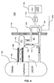
- a liquid level measurement system for measuring a liquid level in a monitored vessel that contains a volume of liquid having an upper surface, and vapor with non-condensable gases comprising a condensing chamber configured to hold a first volume of liquid and to condense the vapor; a steam leg extending between the monitored vessel and the condensing chamber for introducing the vapor and non-condensable gases into the condensing chamber; a variable leg for receiving liquid from the condensing chamber and introducing it into the monitored vessel at a point below the upper surface of the liquid; a reference leg for receiving liquid from a liquid source and introducing the liquid into the condensing chamber; and a differential pressure sensor arranged between the variable leg and the reference leg for measuring a pressure difference.
- an embodiment of a liquid level measuring system 100 will include a monitored vessel 102, such as the RPV of an advanced boiling water reactor (ABWR).
- the monitored vessel 102 will include a lower portion 106 containing a liquid and upper portion 104 primarily containing vapor or steam generated by the evaporation of the liquid.
- the improved condensation chamber (CC) 110 is a smaller vessel with at least three connections which include connections to a reference leg (RL) 118, a variable leg (VL) 114 and a steam leg (SL) 108.
- the RL 118 provides a path for liquid from the make up water system such as from a control rod drive (CRD) drive water system 122 to flow through control valve (PPC) 120 into the CC 110 and begin to accumulate in the CC along with any condensate produced within the CC.
- the VL 114 allows excess liquid to flow from the CC 110 and back into the liquid portion 106 of the monitored vessel 102, thereby maintained both a substantially constant fluid level within the CC (and also the RL 118) and a liquid level within the lower portion of the VL that generally corresponds to the liquid level in the monitored vessel.
- the liquid level within the monitored vessel 102 may then be determined by evaluating the pressure differential ( ⁇ P) determined by sensor 124 between the VL 114, the lower level corresponding to the level within the monitored vessel, and the RL 118, a substantially constant value determined by the relative height of the surface of the liquid maintained within the CC 110.
- the output from the sensor 124 may be transmitted continuously, periodically and/or on demand to appropriate logging and/or control devices through line 124a. As will be appreciated, this difference depends on the relative placement, internal configuration and liquid load of the CC 110 and the monitored vessel 102 respectively.
- the opening from the CC 110 into the VL 114 opening is configured whereby the VL opening is positioned at a higher relative position than the opening from the RL 118 into the CC.
- the VL opening is also positioned at a lower relative position than the opening from the SL 108.
- the SL 108 is connected to the RPV instrument line nozzle safe end.
- Non-condensable gases accumulating in the CC 110 during operation of the vessel and/or system will be generally continuously dissolved in and/or entrained in the liquid entering the CC from the RL 118 and/or the condensate forming in the CC will be carried with the overflow through the VL 114 and returned to the lower portion 106 of the monitored vessel 102.
- the improved CC design will prevent any downward flow of the potentially non-condensable gases enriched water present in the CC 110 from entering the RL opening within the CC. Further, introduction of water through the RL 118 and the "circulating" nature of the movement of fluids through the disclosed system, it is expected that the improved CC design will also reduce the degree of thermal stresses experienced by the CC/line connections during continuous operation. Further, the non-condensable gases accumulating in the CC 110 will tend be continuously returned to the RPV through the SL 108 through simple convection due to their relative bouyancy.
- FIG. 5 A more detailed view of an exemplary embodiment of a condensation chamber according to the invention is illustrated in FIG. 5 which generally corresponds to a portion of FIG. 4.
- the SL 108 extending from the monitored vessel 102 to the CC 110 will typically be relatively short, insulated and of sufficient diameter to avoid condensation of the vapor or steam before reaching the CC.
- a portion of the CC 110 may be provided with heat transfer means, typically utilizing forced and/or natural convection, for cooling one or more inner surfaces of the CC to a temperature sufficient to condense the vapor or steam entering from the monitored vessel 102.
- the VL 114 may be provided with a projection, dam or other structure within the CC 110 that effectively raises the level of the opening into the VL relative to the opening into the CC provided for the RL 118.
- a wide range of fittings and CC configurations may be utilized to establish this vertical separation between the two openings.
- the size of the CC 110, the relative temperatures and flow rates of the liquid entering from the RL 118 and the rate at which condensate is being produced within the CC will determine to some extent the range of liquid temperatures that will be applied to the various components. Through selection of appropriate temperatures and flow rates, one skilled in the art would be able to reduce the range of temperatures to which the components will be exposed during operation, thereby providing way to reduce the thermal stress on the components.
Applications Claiming Priority (1)
| Application Number | Priority Date | Filing Date | Title |
|---|---|---|---|
| US11/220,672 US7845223B2 (en) | 2005-09-08 | 2005-09-08 | Condensing chamber design |
Publications (2)
| Publication Number | Publication Date |
|---|---|
| EP1762830A2 true EP1762830A2 (de) | 2007-03-14 |
| EP1762830A3 EP1762830A3 (de) | 2011-01-05 |
Family
ID=37565124
Family Applications (1)
| Application Number | Title | Priority Date | Filing Date |
|---|---|---|---|
| EP06254601A Withdrawn EP1762830A3 (de) | 2005-09-08 | 2006-09-04 | Füllstandsmesssystem mit einer verbesserten Kondensationskammerskonstruktion |
Country Status (5)
| Country | Link |
|---|---|
| US (1) | US7845223B2 (de) |
| EP (1) | EP1762830A3 (de) |
| JP (1) | JP5291869B2 (de) |
| CN (1) | CN1928515A (de) |
| TW (1) | TWI379984B (de) |
Cited By (3)
| Publication number | Priority date | Publication date | Assignee | Title |
|---|---|---|---|---|
| EP2199759A3 (de) * | 2008-12-22 | 2017-10-25 | General Electric Company | System und Verfahren zum Messen eines Pegels einer Flüssigkeit in einem Behälter |
| CN107358984A (zh) * | 2017-06-07 | 2017-11-17 | 中国核电工程有限公司 | 反应堆严重事故后安全壳内气体浓度监测系统 |
| TWI791274B (zh) * | 2020-09-16 | 2023-02-01 | 巫協森 | 線上測量溶液自動校正液位、容量與濃度的方法及系統 |
Families Citing this family (4)
| Publication number | Priority date | Publication date | Assignee | Title |
|---|---|---|---|---|
| JP6081127B2 (ja) * | 2011-11-11 | 2017-02-15 | 株式会社東芝 | 原子炉水位計の水張り設備 |
| JP6270333B2 (ja) * | 2013-04-16 | 2018-01-31 | 日立Geニュークリア・エナジー株式会社 | 原子炉水位計測装置 |
| US10576393B2 (en) * | 2015-12-18 | 2020-03-03 | General Electric Company | System and method for condensing moisture in a bioreactor gas stream |
| CN111337101A (zh) * | 2020-03-13 | 2020-06-26 | 国家能源集团宁夏煤业有限责任公司 | 液位测量装置 |
Family Cites Families (29)
| Publication number | Priority date | Publication date | Assignee | Title |
|---|---|---|---|---|
| US2232840A (en) * | 1938-02-24 | 1941-02-25 | United Gas Improvement Co | Distillation control |
| US2678434A (en) * | 1949-09-22 | 1954-05-11 | Reliance Gauge Column Company | Electrically operated boiler alarm control device |
| US2870635A (en) * | 1955-10-20 | 1959-01-27 | Justus T Vollbrecht | Compensated water level indicator |
| DE1185830B (de) * | 1962-07-27 | 1965-01-21 | Siemens Ag | Hydrostatischer Fluessigkeitsstandmesser fuer Behaelter von heissen kondensierenden Fluessigkeiten |
| US3164991A (en) * | 1963-02-05 | 1965-01-12 | Robert E Potthoff | Liquid level indicator |
| GB1124961A (en) * | 1965-05-03 | 1968-08-21 | Elliott Brothers London Ltd | Improvements in or relating to apparatus for water level measurement in pressure vessels |
| DE2206957C3 (de) * | 1971-02-12 | 1975-03-20 | Fiat S.P.A., Turin (Italien) | Einrichtung zur Messung des Wasserstandes in Dampferzeugern |
| US4299116A (en) * | 1979-12-03 | 1981-11-10 | Atlantic Richfield Company | Methods involving differential pressure determinations |
| DE3046933C2 (de) * | 1979-12-20 | 1982-12-23 | Tokyo Shibaura Denki K.K., Kawasaki, Kanagawa | Wasserstandsmeßvorrichtung für einen Kernreaktor |
| US4389888A (en) * | 1979-12-21 | 1983-06-28 | Tokyo Shibaura Denki Kabushiki Kaisha | Level meter |
| US4332166A (en) * | 1980-08-08 | 1982-06-01 | International Telephone And Telegraph Corporation | Temperature compensation apparatus for a liquid filled conduit |
| JPS58140689A (ja) * | 1982-02-16 | 1983-08-20 | 株式会社東芝 | 原子炉圧力容器内の水位測定装置 |
| JPS58155317A (ja) * | 1982-03-12 | 1983-09-16 | Hitachi Ltd | 水位計測装置 |
| US4927594A (en) * | 1988-08-10 | 1990-05-22 | Westinghouse Electric Corp. | Thermocouple based control rod position indication system |
| JPH0694506A (ja) * | 1992-09-11 | 1994-04-05 | Hitachi Ltd | 差圧式水位測定装置 |
| US5297174A (en) * | 1993-05-26 | 1994-03-22 | Westinghouse Electric Corp. | Safety system grade apparatus and method for detecting a dropped control rod and malfunctioning exit thermocouples in a pressurized water reactor |
| US5365555A (en) * | 1993-06-23 | 1994-11-15 | General Electric Company | Water level measurement system |
| JP3230923B2 (ja) * | 1994-03-29 | 2001-11-19 | 株式会社東芝 | 原子炉水位測定装置 |
| US5475720A (en) * | 1994-04-08 | 1995-12-12 | Pennsylvania Power & Light Company | Non-condensable gas tolerant condensing chamber |
| DE4421273C2 (de) * | 1994-06-21 | 1996-05-23 | Siemens Ag | Kondensgefäß zur Dampfdruckmessung, Verwendung des Kondensgefäßes für eine Füllstandsmessung und eine Dampfdurchsatzmessung sowie Verfahren zum Betrieb eines Kondensgefäßes |
| US5541969A (en) * | 1994-08-24 | 1996-07-30 | Combustion Engineering, Inc. | Midloop water level monitor |
| US5533074A (en) * | 1995-05-02 | 1996-07-02 | Mansell; Timothy E. | Nuclear reactor coolant level monitoring system |
| DE19648688B4 (de) * | 1996-11-25 | 2006-11-09 | Robert Bosch Gmbh | Verfahren zur Erfassung der Füllstandsmenge eines Tanksystems |
| US5811690A (en) * | 1997-03-20 | 1998-09-22 | Hershey; George E. | Differential pressure transmitter with highly accurate temperature compensation |
| US5901603A (en) * | 1998-07-16 | 1999-05-11 | Isco Inc. | Liquid level monitor |
| FR2784311B1 (fr) * | 1998-10-09 | 2000-12-08 | Air Liquide | Dispositif d'agitation d'un liquide dans un reacteur et d'injection d'un gaz dans ce liquide |
| JP2001317982A (ja) * | 2000-05-02 | 2001-11-16 | Ishikawajima Harima Heavy Ind Co Ltd | ドラムレベル計測装置 |
| DE10156495C1 (de) | 2001-11-16 | 2003-01-02 | Framatome Anp Gmbh | Vorrichtung und Verfahren zum Kühlen eines Reaktordruckbehälters einer Siedewasser-Reaktoranlage |
| US7251998B2 (en) * | 2005-05-25 | 2007-08-07 | Bae Systems Information And Electronic Systems Integration Inc. | Liquid measurement system having a plurality of differential pressure probes |
-
2005
- 2005-09-08 US US11/220,672 patent/US7845223B2/en not_active Expired - Fee Related
-
2006
- 2006-08-28 TW TW095131622A patent/TWI379984B/zh active
- 2006-09-04 EP EP06254601A patent/EP1762830A3/de not_active Withdrawn
- 2006-09-07 JP JP2006243298A patent/JP5291869B2/ja active Active
- 2006-09-08 CN CNA2006101513838A patent/CN1928515A/zh active Pending
Non-Patent Citations (1)
| Title |
|---|
| None |
Cited By (3)
| Publication number | Priority date | Publication date | Assignee | Title |
|---|---|---|---|---|
| EP2199759A3 (de) * | 2008-12-22 | 2017-10-25 | General Electric Company | System und Verfahren zum Messen eines Pegels einer Flüssigkeit in einem Behälter |
| CN107358984A (zh) * | 2017-06-07 | 2017-11-17 | 中国核电工程有限公司 | 反应堆严重事故后安全壳内气体浓度监测系统 |
| TWI791274B (zh) * | 2020-09-16 | 2023-02-01 | 巫協森 | 線上測量溶液自動校正液位、容量與濃度的方法及系統 |
Also Published As
| Publication number | Publication date |
|---|---|
| EP1762830A3 (de) | 2011-01-05 |
| TWI379984B (en) | 2012-12-21 |
| JP5291869B2 (ja) | 2013-09-18 |
| US7845223B2 (en) | 2010-12-07 |
| JP2007071878A (ja) | 2007-03-22 |
| CN1928515A (zh) | 2007-03-14 |
| TW200730777A (en) | 2007-08-16 |
| US20080083276A1 (en) | 2008-04-10 |
Similar Documents
| Publication | Publication Date | Title |
|---|---|---|
| US7845223B2 (en) | Condensing chamber design | |
| US5566571A (en) | Differential pressure detecting equipment capable of preventing accumulation of non-condensible gases | |
| EP0580798B1 (de) | Wassermenge- und speisewasserregelsystem für einen dampferzeuger | |
| US5475720A (en) | Non-condensable gas tolerant condensing chamber | |
| US6865244B2 (en) | Device and method for cooling a reactor pressure vessel of a boiling water reactor plant | |
| US5533074A (en) | Nuclear reactor coolant level monitoring system | |
| JP2007064635A (ja) | 原子炉状態監視装置および原子炉状態監視方法 | |
| WO2012096165A1 (ja) | 水位計測システムおよびその非凝縮性ガス排出装置 | |
| JP3182293B2 (ja) | 水位測定系 | |
| JP5033464B2 (ja) | 液体タンクの液位計測装置 | |
| EP4276854A1 (de) | Strömungssteuerungsvorrichtung, abwärmeabführsystem und strömungsstabilisierungsverfahren | |
| US4643025A (en) | System for measuring liquid level in a pressurized vessel | |
| JP6905451B2 (ja) | 水素濃度測定システム | |
| US4521371A (en) | Vessel liquid level indication | |
| JPH06331784A (ja) | 原子炉水位測定装置 | |
| JP3216465B2 (ja) | 原子炉水位測定装置 | |
| CN117705222A (zh) | 核反应堆t型管两相夹带实验的管内液位精确测量装置及方法 | |
| JP2007101537A (ja) | 改善されたオンライン蒸気流量速度測定デバイスおよび方法 | |
| JPH10177086A (ja) | 原子炉一次冷却材流量の測定装置及び測定方法 | |
| JPS6193986A (ja) | 原子炉非常用減圧装置 | |
| JPH0464098A (ja) | 原子炉プロセス計測制御装置 | |
| JPS5887497A (ja) | 原子炉の水位検知装置 | |
| JPH0362236B2 (de) | ||
| Cai | Column Performance Testing Procedures | |
| JPS6085343A (ja) | 蒸気系圧力検出装置 |
Legal Events
| Date | Code | Title | Description |
|---|---|---|---|
| PUAI | Public reference made under article 153(3) epc to a published international application that has entered the european phase |
Free format text: ORIGINAL CODE: 0009012 |
|
| AK | Designated contracting states |
Kind code of ref document: A2 Designated state(s): AT BE BG CH CY CZ DE DK EE ES FI FR GB GR HU IE IS IT LI LT LU LV MC NL PL PT RO SE SI SK TR |
|
| AX | Request for extension of the european patent |
Extension state: AL BA HR MK YU |
|
| PUAL | Search report despatched |
Free format text: ORIGINAL CODE: 0009013 |
|
| AK | Designated contracting states |
Kind code of ref document: A3 Designated state(s): AT BE BG CH CY CZ DE DK EE ES FI FR GB GR HU IE IS IT LI LT LU LV MC NL PL PT RO SE SI SK TR |
|
| AX | Request for extension of the european patent |
Extension state: AL BA HR MK RS |
|
| 17P | Request for examination filed |
Effective date: 20110705 |
|
| AKX | Designation fees paid |
Designated state(s): DE ES SE |
|
| 17Q | First examination report despatched |
Effective date: 20110922 |
|
| GRAP | Despatch of communication of intention to grant a patent |
Free format text: ORIGINAL CODE: EPIDOSNIGR1 |
|
| INTG | Intention to grant announced |
Effective date: 20190103 |
|
| STAA | Information on the status of an ep patent application or granted ep patent |
Free format text: STATUS: THE APPLICATION IS DEEMED TO BE WITHDRAWN |
|
| 18D | Application deemed to be withdrawn |
Effective date: 20190514 |