EP1759079B1 - Fahrzeugkomponente und verfahren zur sicherung eines schwenkbaren bauteils gegen öffnen im crashfall - Google Patents
Fahrzeugkomponente und verfahren zur sicherung eines schwenkbaren bauteils gegen öffnen im crashfall Download PDFInfo
- Publication number
- EP1759079B1 EP1759079B1 EP05850411.9A EP05850411A EP1759079B1 EP 1759079 B1 EP1759079 B1 EP 1759079B1 EP 05850411 A EP05850411 A EP 05850411A EP 1759079 B1 EP1759079 B1 EP 1759079B1
- Authority
- EP
- European Patent Office
- Prior art keywords
- component
- pivotable
- rotational axis
- crash
- pivotable component
- Prior art date
- Legal status (The legal status is an assumption and is not a legal conclusion. Google has not performed a legal analysis and makes no representation as to the accuracy of the status listed.)
- Expired - Lifetime
Links
Images



Classifications
-
- B—PERFORMING OPERATIONS; TRANSPORTING
- B60—VEHICLES IN GENERAL
- B60N—SEATS SPECIALLY ADAPTED FOR VEHICLES; VEHICLE PASSENGER ACCOMMODATION NOT OTHERWISE PROVIDED FOR
- B60N2/00—Seats specially adapted for vehicles; Arrangement or mounting of seats in vehicles
- B60N2/24—Seats specially adapted for vehicles; Arrangement or mounting of seats in vehicles for particular purposes or particular vehicles
- B60N2/42—Seats specially adapted for vehicles; Arrangement or mounting of seats in vehicles for particular purposes or particular vehicles the seat constructed to protect the occupant from the effect of abnormal g-forces, e.g. crash or safety seats
- B60N2/43—Safety locks
-
- B—PERFORMING OPERATIONS; TRANSPORTING
- B60—VEHICLES IN GENERAL
- B60R—VEHICLES, VEHICLE FITTINGS, OR VEHICLE PARTS, NOT OTHERWISE PROVIDED FOR
- B60R5/00—Compartments within vehicle body primarily intended or sufficiently spacious for trunks, suit-cases, or the like
- B60R5/006—Compartments within vehicle body primarily intended or sufficiently spacious for trunks, suit-cases, or the like stowing or holding means for elongated articles, e.g. skis inside vehicles
-
- E—FIXED CONSTRUCTIONS
- E05—LOCKS; KEYS; WINDOW OR DOOR FITTINGS; SAFES
- E05B—LOCKS; ACCESSORIES THEREFOR; HANDCUFFS
- E05B77/00—Vehicle locks characterised by special functions or purposes
- E05B77/02—Vehicle locks characterised by special functions or purposes for accident situations
- E05B77/04—Preventing unwanted lock actuation, e.g. unlatching, at the moment of collision
- E05B77/06—Preventing unwanted lock actuation, e.g. unlatching, at the moment of collision by means of inertial forces
-
- E—FIXED CONSTRUCTIONS
- E05—LOCKS; KEYS; WINDOW OR DOOR FITTINGS; SAFES
- E05C—BOLTS OR FASTENING DEVICES FOR WINGS, SPECIALLY FOR DOORS OR WINDOWS
- E05C3/00—Fastening devices with bolts moving pivotally or rotatively
- E05C3/12—Fastening devices with bolts moving pivotally or rotatively with latching action
- E05C3/14—Fastening devices with bolts moving pivotally or rotatively with latching action with operating handle or equivalent member rigid with the latch
-
- E—FIXED CONSTRUCTIONS
- E05—LOCKS; KEYS; WINDOW OR DOOR FITTINGS; SAFES
- E05C—BOLTS OR FASTENING DEVICES FOR WINGS, SPECIALLY FOR DOORS OR WINDOWS
- E05C5/00—Fastening devices with bolts moving otherwise than only rectilinearly and only pivotally or rotatively
-
- Y—GENERAL TAGGING OF NEW TECHNOLOGICAL DEVELOPMENTS; GENERAL TAGGING OF CROSS-SECTIONAL TECHNOLOGIES SPANNING OVER SEVERAL SECTIONS OF THE IPC; TECHNICAL SUBJECTS COVERED BY FORMER USPC CROSS-REFERENCE ART COLLECTIONS [XRACs] AND DIGESTS
- Y10—TECHNICAL SUBJECTS COVERED BY FORMER USPC
- Y10T—TECHNICAL SUBJECTS COVERED BY FORMER US CLASSIFICATION
- Y10T292/00—Closure fasteners
- Y10T292/08—Bolts
- Y10T292/0801—Multiple
- Y10T292/0803—Sliding and swinging
- Y10T292/0805—Combined motion
- Y10T292/0806—Lever-operating means
-
- Y—GENERAL TAGGING OF NEW TECHNOLOGICAL DEVELOPMENTS; GENERAL TAGGING OF CROSS-SECTIONAL TECHNOLOGIES SPANNING OVER SEVERAL SECTIONS OF THE IPC; TECHNICAL SUBJECTS COVERED BY FORMER USPC CROSS-REFERENCE ART COLLECTIONS [XRACs] AND DIGESTS
- Y10—TECHNICAL SUBJECTS COVERED BY FORMER USPC
- Y10T—TECHNICAL SUBJECTS COVERED BY FORMER US CLASSIFICATION
- Y10T292/00—Closure fasteners
- Y10T292/42—Rigid engaging means
-
- Y—GENERAL TAGGING OF NEW TECHNOLOGICAL DEVELOPMENTS; GENERAL TAGGING OF CROSS-SECTIONAL TECHNOLOGIES SPANNING OVER SEVERAL SECTIONS OF THE IPC; TECHNICAL SUBJECTS COVERED BY FORMER USPC CROSS-REFERENCE ART COLLECTIONS [XRACs] AND DIGESTS
- Y10—TECHNICAL SUBJECTS COVERED BY FORMER USPC
- Y10T—TECHNICAL SUBJECTS COVERED BY FORMER US CLASSIFICATION
- Y10T292/00—Closure fasteners
- Y10T292/42—Rigid engaging means
- Y10T292/444—Swinging catch
Definitions
- the present invention relates to a vehicle component, preferably the backrest of a seat, which comprises a pivotable component, preferably a through-loading flap, with a latch, wherein the latch has a latching hook, which in case of operation is rotatable about a first axis of rotation from a locking position into an unlocking position, wherein the unlocked pivotable member is foldable about a second axis of rotation in an opening direction from a substantially vertical rest position to a substantially horizontal through-loading position. Furthermore, the present invention relates to a method for securing a pivotable component.
- the passenger compartment and the load compartment in vehicles are often separated by hinged walls, seats or through loading flaps, so that the passenger compartment can be used at least partially as a cargo space.
- This is for example in the DE 41 06 973 A disclosed.
- through-loading flaps have the advantage that long items such as skis can be loaded into a car without having to fold down a seat.
- Object of the present invention is to provide an inexpensive, easy to manufacture and easy to assemble vehicle component, which has a pivoting component with a lock that does not open in an accident.
- the displacement of the axis of rotation according to the invention relative to the pivotable component and / or the latching hook relative to the axis of rotation ensures that the pivotable component can not be unlocked and therefore no luggage can penetrate through the pivotable component into the passenger compartment, if the pivoting component before the crash in the locked resting position was.
- the first axis of rotation relative to the pivotable component, and / or the latching hook relative to the first axis of rotation from a working position in a crash position 29lebbar.
- the pivotable component and / or the latching hook therefore a recess, preferably a link, particularly preferably a slot on, by means of which the first axis of rotation relative to the pivotable member and / or the latching hook is controlled relative to the first axis of rotation 29lebbar.
- the recess leads the axis of rotation and / or the latching hook in the event of a crash in the preferred crash position, so that the pivotable component is no longer unlocked.
- the lock comprises a closing piece, which is fixedly connected to the vehicle component, wherein the latching hook cooperates in the operating case and in the rest position of the pivotable component with the closing piece and prevents flaps of the pivotable member and wherein the pivotable member by rotation of the latching hook to the first axis of rotation and around the closing piece is unlocked around.
- the interaction of the Locking piece with the latching hook locks the pivoting component in case of operation in a simple and secure manner.
- the pivotable component of the locking hook in the event of a crash and in the locked rest position of the pivotable component of the locking hooks frictionally between the striker and the pivotal component and transmits acting in an accident in the opening direction of the pivoting member force on the striker. Due to the frictional connection of the latching hook to the closing piece and the pivotable component and the arrangement between the closing piece and the pivotable component, the forces occurring in an accident are introduced into the structure of the vehicle component and thus at least not completely affect the vehicle occupants.
- the latching hook has a latching means, preferably a nose, which cooperates with the pivotable component and, in the event of a crash and in the locked rest position of the pivotable component, prevents unlocking of the latching hook.
- a locking means in the context of the invention is any means that secures the position of a component and prevents a change in position.
- the latching means secures the unlocking of the pivotable component by preventing the change in the position of the latching hook in the event of a crash.
- the locking means may deform plastically and / or elastically in an accident and optionally act as latching.
- the lock on an unlocking lever which is rotatable about the first axis of rotation and by the rotation of the latching hook is rotatable in the operating case from the locking position to the unlocked position.
- the lock comprises a means, preferably a spring, which holds the first axis of rotation and / or the latching hook in the operating position and preferably returns to the operating position after the crash.
- the agent increases the reliability of the lock and allows the preferred transfer of the latching hook from the crash position in the Operating position after an accident preferably due to the restoring force of the spring that the first axis of rotation and / or the latching hook is transferred back to the operating position, so that the further use of the vehicle component without repair costs is possible if the vehicle component was not damaged in the crash.
- the means can additionally serve to reset the release lever always in its locking position.
- the first axis of rotation shifts relative to the pivotable component and / or the latching hook relative to the first axis of rotation against the force of the means. This ensures that the unlocking of the pivotable component is not already prevented by operating forces occurring, but that for a minimum force is required, which preferably does not occur in the operating case.
- the agent can also be an agent that is plastically deformed during the crash.
- At least the unlocking lever and the locking hook of the latch are made in one piece.
- the number of components is low and the locking cost and easy to manufacture and assemble.
- the pivotable member and / or the lock are made of plastic, which is inexpensive and whereby the vehicle component has a low weight.
- the vehicle component according to the invention is sure that, in the event of a crash, no luggage can penetrate from the cargo space into the passenger compartment through a pivotable component of the vehicle component when the swiveling component was in the locked idle state before the crash.
- the locking of the pivotable component is simple and inexpensive to manufacture and assemble and the vehicle component has a low weight.
- the pivotable component can be reused after a crash without repair effort, if the vehicle component was not damaged in the crash.
- the swiveling component is easy to operate for a passenger.
- Another object of the present invention is a method for securing a pivotable component against opening in the event of a crash according to claim 11.
- the procedure is easy to carry out.
- FIG. 1 shows a vertical cross section through a vehicle component 1 according to the invention, here by a backrest of a seat. Therefore, the term backrest for the vehicle component 1 is used in the following.
- the backrest 1 separates a passenger compartment 4 from a load compartment 20 and has a pivotable component 2, here a through-loading flap, for example for skis.
- the term flap is used for the pivotable component 2.
- the flap 2 is reversibly foldable in the operating case of a here shown and substantially vertical rest position in a substantially horizontal loading position about a second axis of rotation 5 in an open direction, which is represented by the arrow 3.
- the through-loading flap 2 can be reversibly locked to the backrest 1 by means of a lock 8 of the rest position.
- the locking or unlocking of the lock 8 takes place with the release lever 6, which in the case of operation about a first axis of rotation 11, the in FIG. 2 is shown, is rotatable, whereby the flap 2 can be unlocked in an unlocking position.
- Operational case in the sense of the explanations means the normal usage situation of the vehicle in contrast to the crash situation.
- the flap has a recessed grip 7.
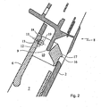
- FIG. 2 shows the lock 8 of the loading hatch 2 from FIG. 1 in a vertical cross-section. Shown is the flap 2, which has the recessed grip 7 for easier handling of the unlocking lever 6.
- the unlocking lever 6 is rotatable about a first axis of rotation 11.
- the illustration shows the lock 8 in the operating case in the locked position.
- the first axis of rotation 11 is located in the operating position 18. Also visible is a recess 12, here a slot in which the first axis of rotation 11 shifts relative to the flap 2 in a crash position 19 in the event of a crash in the embodiment shown here.
- the first axis of rotation 11 is formed here by a bolt 13.
- a closing piece 9 is rotated.
- the closing piece 9 is in a receptacle 10 for the closing piece. 9 arranged.
- the latching hook 17 is arranged in the locking position between the striker 9 and the flap 2 and rotates around the striker 9 upon rotation about the first axis of rotation 11 so that the flap 2 is unlocked.
- the latching hook 17 on a locking means 16, here a nose is secured to secure in the event of a crash.
- FIG. 3 shows the lock 8 FIG. 2 in locking position during operation.
- the latching hook 17 and / or the first axis of rotation 11 or the pin 13, which forms the first axis of rotation 11 in this embodiment, are held in the operating position 18 by a means 14, here a spring.
- a means 14 here a spring.
- the term spring is used for the means 14.
- the release lever is held by the spring in the illustrated locking position.
- FIG. 4 shows the lock FIG. 2 in unlocking position during operation.
- the flap 2 By rotation of the unlocking lever 6 against the spring force of the spring 14 and thereby of the latching hook 17 about the first axis of rotation 11 and the pin 13, the flap 2 is unlocked, wherein the pin 13 remains in the operating position 18.
- the spring 14 is tensioned when unlocking and leads the latching hook 17 preferably in the locking position.
- FIG. 5 shows the lock FIG. 2 in locking position in the event of a crash.
- the first axis of rotation 11 and the pin 13 is displaced in the recess 12 relative to the flap 2 in the crash position 19 to the right in this embodiment.
- the latching hook 17 acts frictionally between the stationary arranged closing piece 9 and the flap 2, and introduces the forces occurring in the structure of the seat.
- the latching hook 17 has a latching means 16, here a nose, which rests at least partially in the event of a crash on the flap 2 and prevents the unlocking of the latching hook 17 ..
- the displacement of the first axis of rotation 11 takes place against the force of the spring 14 and is after Crash due to the restoring force of the spring 14 again transferred to the operating position 18.
- FIG. 6a shows the flap 2 with the lock 8 FIG. 2 in a horizontal cross-section in the locking position during operation.
- the release lever 6 and the latching hook 17 with the latching means 16 are integrally and about the pin 13, which forms the first axis of rotation 11, rotatable.
- the bolt 13 is held in two recesses 12 of the flap 2 in the operating position 18 of two springs 14.
- the closing piece 9 is arranged in the receptacle 10 for the closing piece 9, so that the latching hook 17 is arranged between the closing piece 9 and the flap 2 and the flap 2 is locked.
- FIG. 6b shows the flap 2 with the lock 8 FIG. 2 in a horizontal cross section in the locking position in the event of a crash.
- the bolt 3 By acting on the flap 2 in the opening direction 3 of the flap 2 force 15, the bolt 3 moves in the recesses 12 against the force of the springs 14 in the crash position 19.
- the latching hook 17 In this position, the latching hook 17 is frictionally between the closing means 9 and the flap 2 arranged and the locking lug 16 prevents the unlocking of the latching hook 17th
- the vehicle component is useful in a variety of vehicle types, such as automobiles, aircraft, or ships. It is for example a seat of a vehicle or a wall.
Landscapes
- Engineering & Computer Science (AREA)
- Mechanical Engineering (AREA)
- Aviation & Aerospace Engineering (AREA)
- Transportation (AREA)
- Lock And Its Accessories (AREA)
- Seats For Vehicles (AREA)
Description
- Die vorliegende Erfindung betrifft eine Fahrzeugkomponente, vorzugsweise die Rückenlehne eines Sitzes, die ein schwenkbares Bauteil, vorzugsweise eine Durchladeklappe, mit einer Verriegelung umfasst, wobei die Verriegelung einen Rasthaken aufweist, der im Betriebsfall um eine erste Drehachse von einer Verriegelungsposition in eine Entriegelungsposition drehbar ist, wobei das entriegelte schwenkbare Bauteil um eine zweite Drehachse in einer Öffnenrichtung von einer Im wesentlichen vertikalen Ruheposition in eine im wesentlichen horizontale Durchladeposition klappbar ist. Des weiteren betrifft die vorliegende Erfindung ein Verfahren zur Sicherung eines schwenkbaren Bauteils.
- Zur Vergrößerung des Ladevolumens sind In Fahrzeugen häufig der Fahrgastraum und der Laderaum durch klappbare Wände, Sitze oder durch Durchladeklappen getrennt, so dass der Fahrgastraum zumindest teilweise als Laderaum nutzbar Ist. Dies ist beispielsweise in der
DE 41 06 973 A offenbart. Insbesondere Durchladeklappen haben den Vorteil, dass lange Gegenstände wie Skier in einen PKW geladen werden können, ohne dass ein Sitz umgeklappt werden muss. Um zu gewährleisten, dass zumindest bei zugeklappten Wänden, Sitzen oder Durchladeldappen bei einem Unfall kein Gepäck in den Fahrgastraum dringt oder die Durchladeklappe aufspringt, muss sichergestellt werden, dass durch die bei einem Unfall auf die Wände, Sitze oder die Durchladeklappe wirkenden Kräfte diese nicht aufklappen. - Aufgabe der vorliegenden Erfindung ist eine kostengünstige, einfach herstellbare und einfach montierbare Fahrzeugkomponente zur Verfügung zu stellen, die ein schwenkbares Bauteil mit einer Verriegelung aufweist, die bei einem Unfall nicht aufklappt.
- Die Aufgabe wird gelöst mit einer Fahrzeugkomponente gemäß Patentanspruch 1.
- Die erfindungsgemäße Verschiebung der Drehachse relativ zum schwenkbaren Bauteil und/oder des Rasthakens relativ zur Drehachse stellt sicher, dass das schwenkbare Bauteil nicht entriegelbar ist und daher kein Gepäck durch das schwenkbare Bauteil in den Fahrgastraum dringen kann, wenn sich das schwenkbare Bauteil vor dem Crash in der verriegelten Ruheposition befand. Eine Ausführungsform, In der der Rasthaken im Crashfall reversibel so mit dem schwenkbaren Bauteil zusammenwirkt, dass dieses nicht entriegelbar ist, lässt eine Weiterverwendung der Fahrzeugkomponente ohne Reparaturaufwand zu, wenn diese nicht bei dem Crash beschädigt wurde.
- Erfindungsgemäß ist die erste Drehachse relativ zu dem schwenkbaren Bauteil, und/oder der Rasthaken relativ zur ersten Drehachse, von einer Betriebsposition in eine Crashposition verschlebbar. Vorzugsweise weist das schwenkbare Bauteil und/oder der Rasthaken deshalb eine Ausnehmung, bevorzugt eine Kulisse, besonders bevorzugt ein Langloch, auf, mittels der die erste Drehachse relativ zu dem schwenkbaren Bauteil und/oder der Rasthaken relativ zur ersten Drehachse kontrolliert verschlebbar ist. Die Ausnehmung führt die Drehachse und/oder den Rasthaken im Crashfall in die bevorzugte Crashposition, so dass das schwenkbare Bauteil nicht mehr entriegelbar ist.
- In einer bevorzugten Ausführungsform umfasst die Verriegelung ein Schließstück, welches ortsfest mit der Fahrzeugkomponente verbunden ist, wobei der Rasthaken im Betriebsfall und In Ruheposition des schwenkbaren Bauteils mit dem Schließstück zusammenwirkt und ein Klappen des schwenkbaren Bauteils verhindert und wobei das schwenkbare Bauteil durch Drehung des Rasthakens um die erste Drehachse und um das Schließstück herum entriegelbar ist. Das Zusammenwirken des Schließstücks mit dem Rasthaken verriegelt das schwenkbare Bauteil im Betriebsfall in einer einfachen und sicheren Weise.
- Vorzugsweise wirkt im Crashfall und in verriegelter Ruheposition des schwenkbaren Bauteils der Rasthaken kraftschlüssig zwischen dem Schließstück und dem schwenkbaren Bauteil und überträgt die bei einem Unfall in Öffnenrichtung des schwenkbaren Bauteils wirkende Kraft auf das Schließstück. Aufgrund der kraftschlüssigen Verbindung des Rasthakens zum Schließstück und dem schwenkbaren Bauteil und der Anordnung zwischen dem Schließstück und dem schwenkbaren Bauteil werden die bei einem Unfall auftretenden Kräfte in die Struktur der Fahrzeugkomponente eingeleitet und wirken somit zumindest nicht vollständig auf die Fahrzeuginsassen ein.
- In einer bevorzugten Ausführungsform weist der Rasthaken ein Rastmittel, bevorzugt eine Nase, auf, das mit dem schwenkbaren Bauteil zusammenwirkt und im Crashfall und in verriegelter Ruheposition des schwenkbaren Bauteils das Entriegeln des Rasthakens verhindert. Ein Rastmittel im Sinne der Erfindung ist jedes Mittel, dass die Position eines Bauteils sichert und eine Veränderung der Position verhindert. Das Rastmittel sichert die Entriegelung des schwenkbaren Bauteils, indem es im Crashfall die Änderung der Position des Rasthakens verhindert. Das Rastmittel kann sich bei einem Unfall plastisch und/oder elastisch verformen und gegebenenfalls auch so rastend wirken.
- In einer bevorzugten Ausführungsform weist die Verriegelung einen Entriegelungshebel auf, der um die erste Drehachse drehbar ist und durch dessen Drehung der Rasthaken im Betriebsfall von der Verriegelungsposition in die Entriegelungsposition drehbar ist. Mit dem Entriegelungshebel ist eine einfache Bedienung des schwenkbaren Bauteils möglich.
- In einer bevorzugten Ausführungsform umfasst die Verriegelung ein Mittel, bevorzugt eine Feder, das die erste Drehachse und/oder den Rasthaken in der Betriebsposition hält und vorzugsweise nach dem Crash wieder in die Betriebsposition überführt. Das Mittel erhöht die Betriebssicherheit der Verriegelung und ermöglicht durch die bevorzugte Überführung des Rasthakens aus der Crashposition in die Betriebsposition nach einem Unfall bevorzugt aufgrund der Rückstellkraft der Feder, dass die erste Drehachse und/oder der Rasthaken wieder In die Betriebsposition überführt wird, so dass die Weiterverwendung der Fahrzeugkomponente ohne Reparaturaufwand möglich ist, wenn die Fahrzeugkomponente bei dem Crash nicht beschädigt wurde. Das Mittel kann zusätzlich dazu dienen den Entriegelungshebel Immer in seine Verriegelungsposition zurückzustellen. Bevorzugt verschiebt sich im Crashfall die erste Drehachse relativ zu dem schwenkbaren Bauteil und/oder der Rasthaken relativ zur ersten Drehachse gegen die Kraft des Mittels. Dadurch ist sichergestellt, dass das Entriegeln des schwenkbaren Bauteils nicht bereits durch Im Betriebsfall auftretende Kräfte verhindert wird, sondern dass dafür eine Mindestkraft erforderlich ist, die im Betriebsfall bevorzugt nicht auftritt. Das Mittel kann auch ein Mittel sein, das beim Crash plastisch verformt wird.
- Vorzugsweise sind zumindest der Entriegelungshebel und der Rasthaken der Verriegelung einstückig hergestellt. Dadurch ist die Bauteilezahl gering und die Verriegelung kostengünstig und einfach herstell- und montierbar. Bevorzugt sind das schwenkbare Bauteil und/oder die Verriegelung aus Kunststoff hergestellt, was kostengünstig ist und wodurch die Fahrzeugkomponente ein geringes Gewicht aufweist.
- Die erfindungsgemäße Fahrzeugkomponente steilt sicher, dass bei einem Crash kein Gepäck durch ein schwenkbares Bauteil der Fahrzeugkomponente vom Laderaum in den Fahrgastraum dringen kann, wenn sich das schwenkbare Bauteil vor dem Crash im verriegelten Ruhezustand befand. Die Verriegelung des schwenkbaren Bauteils ist einfach und kostengünstig herstell- und montierbar und die Fahrzeugkomponente weist ein geringes Gewicht auf. Bevorzugt kann das schwenkbare Bauteil nach einem Crash ohne Reparaturaufwand wiederverwendet werden, wenn die Fahrzeugkomponente bei dem Crash nicht beschädigt wurde. Das schwenkbare Bauteil ist für einen Fahrgast einfach bedienbar.
- Ein weiterer Gegenstand der vorliegenden Erfindung ist ein Verfahren zur Sicherung , eines schwenkbaren Bauteils gegen Öffnen Im Crashfall gemäß Patentanspruch 11.
- Das Verfahren ist einfach durchführbar.
- Im folgenden wird die Erfindung durch
Figuren 1 - 6b erläutert. Die Erläuterungen sind lediglich beispielhaft und schränken den allgemeinen Erfindungsgedanken nicht ein. Die Erläuterungen geiten gleichermaßen für die erfindungsgemäße Fahrzeugkomponente und das erfindungsgemäße Verfahren. - Figur 1
- zeigt einen vertikalen Querschnitt durch eine erfindungsgemäße Fahrzeugkomponente, hier durch eine Rückenlehne eines Sitzes.
- Figur 2
- zeigt die Verriegelung des schwenkbaren Bauteils, hier einer Durchladeklappe, der Fahrzeugkomponente aus
Figur 1 in einem vertikalen Querschnitt. - Figur 3
- zeigt die Verriegelung aus
Figur 2 In Verriegelungsposition Im Betriebsfall. - Figur 4
- zeigt die Verriegelung aus
Figur 2 in Entriegelungsposition im Betriebsfall. - Figur 5
- zeigt die Verriegelung aus
Figur 2 in Verriegelungsposition im Crashfall. - Figur 6a
- zeigt das schwenkbare Bauteil 2 mit der Verriegelung 8 aus
Figur 2 in einem horizontalen Querschnitt in Verriegelungsposition im Betriebsfall. - Figur 6b
- zeigt das schwenkbare Bauteil 2 mit der Verriegelung 8 aus
Figur 2 in einem horizontalen Querschnitt in Verriegelungsposition im Crashfall. -
Figur 1 zeigt einen vertikalen Querschnitt durch eine erfindungsgemäße Fahrzeugkomponente 1, hier durch eine Rückenlehne eines Sitzes. Daher wird im folgenden der Begriff Rückenlehne für die Fahrzeugkomponente 1 verwendet. Die Rückenlehne 1 trennt einen Fahrgastraum 4 von einem Laderaum 20 und weist ein schwenkbares Bauteil 2 auf, hier eine Durchladeklappe, beispielsweise für Skier. Im folgenden wird daher der Begriff Klappe für das schwenkbare Bauteil 2 verwendet. Die Klappe 2 ist im Betriebsfall von einer hier dargestellten und im wesentlichen vertikalen Ruheposition in eine im wesentlichen horizontale Durchladeposition um eine zweite Drehachse 5 in einer Öffnenrichtung reversibel klappbar, was durch den Pfeil 3 dargestellt ist. Die Durchladeklappe 2 ist mit der Rückenlehne 1 mittels einer Verriegelung 8 der Ruheposition reversibel verriegelbar. Die Ver- bzw. Entriegelung der Verriegelung 8 erfolgt mit dem Entriegelungshebel 6, der im Betriebsfall um eine erste Drehachse 11, die inFigur 2 dargestellt ist, drehbar ist, wodurch die Klappe 2 in eine Entriegelungsposition entriegelbar ist. Betriebsfall im Sinne der Erläuterungen bedeutet die normale Nutzungssituation des Fahrzeugs im Gegensatz zu der Crashsituation. Zur leichteren Handhabung des Entriegelungshebels 6 weist die , Klappe eine Griffmulde 7 auf. -
Figur 2 zeigt die Verriegelung 8 der Durchladeklappe 2 ausFigur 1 in einem vertikalen Querschnitt. Dargestellt ist die Klappe 2, die die Griffmulde 7 zur einfacheren Handhabung des Entriegelungshebels 6 aufweist. Der Entriegelungshebel 6 ist um eine erste Drehachse 11 drehbar. Die Darstellung zeigt die Verriegelung 8 im Betriebsfall in Verriegelungsposition. Die erste Drehachse 11 befindet sich in der Betriebsposition 18. Sichtbar ist ebenfalls eine Ausnehmung 12, hier ein Langloch, in dem sich im Crashfall in der hier dargestellten Ausführungsform die erste Drehachse 11 relativ zur Klappe 2 in eine Crashposition 19 verschiebt. Die erste Drehachse 11 wird hier durch einen Bolzen 13 gebildet. Bei Drehung des Entriegelungshebels 6 um die erste Drehachse 11 wird der Rasthaken 17, der in dieser Ausführungsform der Fahrzeugkomponente 1 einstückig mit dem Entriegelungshebel 6 ist, um die erste Drehachse 11 und um ein Schließstück 9 gedreht. Das Schließstück 9 ist in einer Aufnahme 10 für das Schließstück 9 angeordnet. Der Rasthaken 17 ist in der Verriegelungsposition zwischen dem Schließstück 9 und der Klappe 2 angeordnet und dreht sich bei Drehung um die erste Drehachse 11 um das Schließstück 9 herum, so dass die Klappe 2 entriegelt wird. Zur Sicherung im Crashfall weist der Rasthaken 17 ein Rastmittel 16 auf, hier eine Nase. -
Figur 3 zeigt die Verriegelung 8 ausFigur 2 in Verriegelungsposition im Betriebsfall. Der Rasthaken 17 und/oder die erste Drehachse 11 bzw. der Bolzen 13, der in dieser Ausführungsform die erste Drehachse 11 bildet, werden durch ein Mittel 14, hier eine Feder, in der Betriebsposition 18 gehalten. Im folgenden wird der Begriff Feder für das Mittel 14 verwendet. Zusätzlich wird der Entriegelungshebel durch die Feder in der dargestellten Verriegelungsposition gehalten. -
Figur 4 zeigt die Verriegelung ausFigur 2 in Entriegelungsposition im Betriebsfall. Durch Drehung des Entriegelungshebels 6 gegen die Federkraft der Feder 14 und dadurch des Rasthakens 17 um die erste Drehachse 11 bzw. den Bolzen 13 wird die Klappe 2 entriegelt, wobei der Bolzen 13 in der Betriebsposition 18 verbleibt. Dadurch, dass sich die Drehachse 11 in der linken Betriebsposition befindet kann die Rastnase an der Klappe 2 vorbeigedreht werden. Die Feder 14 wird beim Entriegeln gespannt und führt den Rasthaken 17 bevorzugt in die Verriegelungsposition zurück. -
Figur 5 zeigt die Verriegelung ausFigur 2 in Verriegelungsposition im Crashfall. Durch eine Kraft 15 in Öffnungsrichtung 3 der Klappe 2 wird in dieser Ausführungsform die erste Drehachse 11 bzw. der Bolzen 13 in der Ausnehmung 12 relativ zur Klappe 2 in die Crashposition 19 nach rechts verschoben. Dadurch kann der Rasthaken nicht mehr an der Klappe 2 vorbei in die Entriegelungsposition drehen. Der Rasthaken 17 wirkt kraftschlüssig zwischen dem ortsfest angeordneten Schließstück 9 und der Klappe 2, und leitet die auftretenden Kräfte in die Struktur des Sitzes ein. Zusätzlich weist der Rasthaken 17 ein Rastmittel 16, hier eine Nase auf, das im Crashfall an der Klappe 2 zumindest teilweise anliegt und das Entriegeln des Rasthakens 17 verhindert.. Die Verschiebung der ersten Drehachse 11 erfolgt gegen die Kraft der Feder 14 und wird nach dem Crash aufgrund der Rückstellkraft der Feder 14 wieder in die Betriebsposition 18 überführt. -
Figur 6a zeigt die Klappe 2 mit der Verriegelung 8 ausFigur 2 in einem horizontalen Querschnitt in Verriegelungsposition im Betriebsfall. Der Entriegelungshebel 6 und der Rasthaken 17 mit dem Rastmittel 16 sind einstückig und um den Bolzen 13, der die erste Drehachse 11 bildet, drehbar. Der Bolzen 13 ist in zwei Ausnehmungen 12 der Klappe 2 in Betriebsposition 18 von zwei Federn 14 gehalten. Das Schließstück 9 ist in der Aufnahme 10 für das Schließstück 9 angeordnet, so dass der Rasthaken 17 zwischen dem Schließstück 9 und der Klappe 2 angeordnet und die Klappe 2 verriegelt ist. -
Figur 6b zeigt die Klappe 2 mit der Verriegelung 8 ausFigur 2 in einem horizontalen Querschnitt in Verriegelungsposition im Crashfall. Durch eine auf die Klappe 2 in Öffnenrichtung 3 der Klappe 2 wirkende Kraft 15 verschiebt sich der Bolzen 3 in den Ausnehmungen 12 gegen die Kraft der Federn 14 in die Crashposition 19. In dieser Position ist der Rasthaken 17 kraftschlüssig zwischen dem Schließmittel 9 und der Klappe 2 angeordnet und die Rastnase 16 verhindert das Entriegeln des Rasthakens 17. - Die Fahrzeugkomponente ist in einer Vielzahl von Fahrzeugtypen verwendbar, beispielsweise in Kraftfahrzeugen, Flugzeugen oder Schiffen. Sie ist beispielsweise ein Sitz eines Fahrzeugs oder eine Wand.
-
- 1
- Fahrzeugkomponente, beispielsweise Rückenlehne eines Sitzes
- 2
- Schwenkbares Bauteil, beispielsweise Klappe oder Durchladeklappe
- 3
- Öffnenrichtung des schwenkbaren Bauteils
- 4
- Fahrzeuginnenraum
- 5
- Zweite Drehachse
- 6
- Entriegelungshebel
- 7
- Griffmulde
- 8
- Verriegelung
- 9
- Schließstück
- 10
- Aufnahme für das Schließstück
- 11
- Erste Drehachse
- 12
- Ausnehmung, beispielsweise Kulisse oder Langloch
- 13
- Bolzen, der die erste Drehachse bildet
- 14
- Feder
- 15
- In Öffnenrichtung wirkende Kraft
- 16
- Rastmittel, beispielsweise Nase
- 17
- Rasthaken
- 18
- Betriebsposition
- 19
- Crashposition
- 20
- Laderaum
Claims (11)
- Fahrzeugkomponente (1) zur Trennung des Fahrgastraums und des Laderaums, die ein schwenkbares Bauteil (2) mit einer Verriegelung (8) umfasst, wobei die Verriegelung (8) einen Rasthaken (17) aufweist, der im Betriebsfall und bei verriegeltem Bauteil mit einem Schließstück (9) zusammenwirkt und im Betriebsfall um eine erste Drehachse (11) von einer Verriegelungsposition in eine Entriegelungsposition drehbar ist, wobei das entriegelte schwenkbare Bauteil (2) um eine zweite Drehachse (5) in einer Öffnenrichtung (3) von einer im wesentlichen vertikalen Ruheposition in eine im wesentlichen horizontale Durchladeposition (3) klappbar ist, so dass der Fahrgastraum zumindest teilweise als Laderaum nutzbar ist, dadurch gekennzeichnet, dass sich bei einem in der verriegelten Ruheposition befindlichen schwenkbaren Bauteil (2) durch eine in Öffnenrichtung (3) des schwenkbaren Bauteils (2) wirkende Kraft (15) die erste Drehachse (11) relativ zu dem schwenkbaren Bauteil (2), und/oder der Rasthaken (17) relativ zur ersten Drehachse (11), von einer Betriebsposition (18) in eine Crashposition (19) verschiebt, so dass der Rasthaken (17) vorzugsweise reversibel so mit dem schwenkbaren Bauteil (2) zusammenwirkt, dass es nicht entriegelbar ist.
- Fahrzeugkomponente (1) nach Anspruch 1, dadurch gekennzeichnet, dass das schwenkbare Bauteil und/oder der Rasthaken (17) eine Ausnehmung (12), bevorzugt eine Kulisse, besonders bevorzugt ein Langloch, aufweist, mittels der die erste Drehachse (11) relativ zu dem schwenkbaren Bauteil (2) und/oder der Rasthaken (17) relativ zur ersten Drehachse (11) verschiebbar ist.
- Fahrzeugkomponente (1) nach einem der vorherigen Ansprüche, dadurch gekennzeichnet, dass die Verriegelung (8) ein Schließstück (9) umfasst, welches ortsfest mit der Fahrzeugkomponente (1) verbunden ist, dass der Rasthaken (17) im Betriebsfall und in Ruheposition des schwenkbaren Bauteils (2) mit dem Schließstück (9) zusammenwirkt und dadurch ein Klappen des schwenkbaren Bauteils (2) verhindert und dass das schwenkbare Bauteil (2) durch Drehung des Rasthakens (17) um die erste Drehachse (11) und um das Schließstück (9) herum entriegelbar ist.
- Fahrzeugkomponente (1) nach einem der vorherigen Ansprüche, dadurch gekennzeichnet, dass im Crashfall und in verriegelter Ruheposition des schwenkbaren Bauteils (2) der Rasthaken (17) kraftschlüssig zwischen dem Schließstück (9) und dem schwenkbaren Bauteil (2) wirkt und die in Öffnenrichtung (3) des schwenkbaren Bauteils (2) wirkende Kraft (15) auf das Schließstück (9) überträgt.
- Fahrzeugkomponente (1) nach einem der vorherigen Ansprüche, dadurch gekennzeichnet, dass der Rasthaken (17) ein Rastmittel (16), bevorzugt eine Nase, aufweist, das mit dem schwenkbaren Bauteil (2) zusammenwirkt und im Crashfall und in verriegelter Ruheposition des schwenkbaren Bauteils (2) das Entriegeln des Rasthakens (17) verhindert.
- Fahrzeugkomponente (1) nach einem der vorherigen Ansprüche, dadurch gekennzeichnet, dass die Verriegelung (8) einen Entriegelungshebel (6) aufweist, der im Betriebsfall um die erste Drehachse (11) drehbar ist und durch dessen Drehung der Rasthaken (17) von der Verriegelungsposition in die Entriegelungsposition drehbar ist.
- Fahrzeugkomponente (1) nach einem der vorherigen Ansprüche, dadurch gekennzeichnet, dass die Verriegelung (8) ein Mittel (14), bevorzugt eine Feder, umfasst, das die erste Drehachse (11) und/oder den Rasthaken (17) in der Betriebsposition (18) hält und vorzugsweise nach dem Crash wieder in die Betriebsposition (18) überführt.
- Fahrzeugkomponente (1) nach einem der vorherigen Ansprüche, dadurch gekennzeichnet, dass sich im Crashfall die erste Drehachse (11) relativ zu dem schwenkbaren Bauteil (2) und/oder der Rasthaken (17) relativ zur ersten Drehachse (11) gegen die Kraft des Mittels (14) verschiebt.
- Fahrzeugkomponente (1) nach einem der voranstehenden Ansprüche, dadurch gekennzeichnet, dass das Mittel (14) den Entriegelungshebel (6) in der Verriegelungsposition hält.
- Fahrzeugkomponente (1) nach einem der vorherigen Ansprüche, dadurch gekennzeichnet, dass zumindest der Entriegelungshebel (6) und der Rasthaken (17) der Verriegelung (8) einstückig sind.
- Verfahren zur Sicherung eines schwenkbaren Bauteils (2) einer Fahrzeugkomponente (1) gemäß Anspruch 1 gegen Öffnen im Crashfall, mittels einer Verriegelung (8), die einen Rasthaken (17) aufweist, der im Betriebsfall um eine erste Drehachse (11) von einer Verriegelungsposition in eine Entriegelungsposition drehbar ist, verriegelbar ist, wobei das entriegelte schwenkbare Bauteil (2) um eine zweite Drehachse (5) in einer Öffnenrichtung (3) von einer im wesentlichen vertikalen Ruheposition in eine im wesentlichen horizontale Durchladeposition (3) klappbar ist, dadurch gekennzeichnet, dass die erste Drehachse (11) im Crashfall in verriegelter Ruheposition des schwenkbaren Bauteils (2) durch eine in Öffnenrichtung (3) des schwenkbaren Bauteils (2) wirkende Kraft vorzugsweise reversibel so verschoben wird, dass das schwenkbare Bauteil (2) nicht entriegelt werden kann, indem der Rasthaken (17) relativ zur ersten Drehachse (11), von einer Betriebsposition (18) in eine Crashposition (19) verschoben wird, so dass der Rasthaken (17) vorzugsweise reversibel so mit dem schwenkbaren Bauteil (2) zusammenwirkt, dass es nicht entriegelbar ist.
Applications Claiming Priority (2)
| Application Number | Priority Date | Filing Date | Title |
|---|---|---|---|
| DE200410028846 DE102004028846B3 (de) | 2004-06-16 | 2004-06-16 | Fahrzeugkomponente und Verfahren zur Sicherung einer Klappe gegen Öffnen im Crashfall |
| PCT/EP2005/052636 WO2006063871A1 (de) | 2004-06-16 | 2005-06-08 | Fahrzeugkomponente und verfahren zur sicherung eines schwenkbaren bauteils gegen öffnen im crashfall |
Publications (2)
| Publication Number | Publication Date |
|---|---|
| EP1759079A1 EP1759079A1 (de) | 2007-03-07 |
| EP1759079B1 true EP1759079B1 (de) | 2015-12-09 |
Family
ID=35456916
Family Applications (1)
| Application Number | Title | Priority Date | Filing Date |
|---|---|---|---|
| EP05850411.9A Expired - Lifetime EP1759079B1 (de) | 2004-06-16 | 2005-06-08 | Fahrzeugkomponente und verfahren zur sicherung eines schwenkbaren bauteils gegen öffnen im crashfall |
Country Status (5)
| Country | Link |
|---|---|
| US (1) | US8864184B2 (de) |
| EP (1) | EP1759079B1 (de) |
| JP (1) | JP4733118B2 (de) |
| DE (1) | DE102004028846B3 (de) |
| WO (1) | WO2006063871A1 (de) |
Families Citing this family (4)
| Publication number | Priority date | Publication date | Assignee | Title |
|---|---|---|---|---|
| DE102007060319B4 (de) * | 2007-03-21 | 2016-04-28 | Johnson Controls Gmbh | Durchladeklappe für einen Fahrzeugsitz |
| JP5308046B2 (ja) * | 2008-03-27 | 2013-10-09 | ダイハツ工業株式会社 | 車両用シートの取付け構造 |
| DE102009058988A1 (de) | 2009-12-18 | 2011-06-22 | Dr. Ing. h.c. F. Porsche Aktiengesellschaft, 70435 | Kraftfahrzeug |
| FR2976870A1 (fr) * | 2011-06-21 | 2012-12-28 | Peugeot Citroen Automobiles Sa | Dispositif de fixation securisee du rang arriere d'un vehicule automobile a la tole de fond de coffre et vehicule automobile associe. |
Family Cites Families (28)
| Publication number | Priority date | Publication date | Assignee | Title |
|---|---|---|---|---|
| US3679259A (en) * | 1970-11-25 | 1972-07-25 | Ford Motor Co | Seat back latch |
| US4010979A (en) * | 1976-05-24 | 1977-03-08 | Fisher Iii Alfred J | Latch structure for vehicle seats |
| US4143913A (en) * | 1977-07-15 | 1979-03-13 | The Firestone Tire & Rubber Company | Seat back hinge |
| DE2941235A1 (de) * | 1979-10-11 | 1981-04-23 | Volkswagenwerk Ag, 3180 Wolfsburg | Verriegelungseinrichtung fuer eine lehne in einem fahrzeug |
| US4365837A (en) * | 1981-03-05 | 1982-12-28 | Hoover Universal, Inc. | Inertial lock |
| JPS58181612A (ja) * | 1982-04-20 | 1983-10-24 | Asahi Glass Co Ltd | 電磁シ−ルド性を有するプラスチツク成形品の製法 |
| CA1232527A (en) * | 1985-10-25 | 1988-02-09 | Martyn Hiscox | Inertial latching mechanism for seat assemblies |
| US4733912A (en) * | 1986-10-30 | 1988-03-29 | Fisher Dynamics Corporation | Inertia sensitive seat hinge mechanism |
| DE3825781A1 (de) * | 1988-07-29 | 1990-02-01 | Bayerische Motoren Werke Ag | Der rueckenlehne eines kraftfahrzeugsitzes zugeordnete armlehne |
| DE4106973C2 (de) * | 1991-03-05 | 1994-10-06 | Daimler Benz Ag | Transportvorrichtung, insbesondere für Skier in einem Kraftwagen |
| US5546502A (en) * | 1993-03-19 | 1996-08-13 | Ricoh Company, Ltd. | Automatic invocation of computational resources without user intervention |
| DE4312732C1 (de) * | 1993-04-20 | 1994-12-01 | Keiper Recaro Gmbh Co | Drehgelenk für Rückenlehnen einer Sitzbank im Kraftfahrzeugfond |
| US5425568A (en) * | 1994-04-11 | 1995-06-20 | General Motors Corporation | Van-type vehicle seat with a seatback-mounted armrest |
| JPH08256875A (ja) * | 1995-03-20 | 1996-10-08 | Araco Corp | 車両用アームレストのロック機構 |
| US5577805A (en) * | 1995-10-10 | 1996-11-26 | General Motors Corporation | Van-type vehicle seat |
| DE59608133D1 (de) * | 1995-11-20 | 2001-12-13 | Volkswagen Ag | Kraftfahrzeug mit einer Rücksitzbank |
| US6236768B1 (en) * | 1997-10-14 | 2001-05-22 | Massachusetts Institute Of Technology | Method and apparatus for automated, context-dependent retrieval of information |
| DE19756344A1 (de) * | 1997-12-18 | 1999-06-24 | Bayerische Motoren Werke Ag | Sicherungseinrichtung an einem Türgriff eines Kraftfahrzeugs |
| JP3487179B2 (ja) * | 1998-06-12 | 2004-01-13 | 三菱自動車工業株式会社 | トランクスルー装置 |
| JP3406530B2 (ja) * | 1999-01-11 | 2003-05-12 | 株式会社タチエス | 車両用ヒンジ付きシートのシートバック構造 |
| US6581050B1 (en) * | 1999-04-20 | 2003-06-17 | Microsoft Corporation | Learning by observing a user's activity for enhancing the provision of automated services |
| DE10004021C1 (de) * | 2000-01-31 | 2001-06-28 | Butz Peter Verwaltung | Transportbehälter-Einrichtung für den Einbau in Kraftfahrzeuge, wie z. B. Durchladeeinrichtung |
| US6523029B1 (en) * | 2000-03-24 | 2003-02-18 | Bitmobile Technologies | System and method for embedded information retrieval in a distributed free-text application environment |
| FR2828149B1 (fr) * | 2000-12-26 | 2003-12-05 | Plasthom S A | Dispositif de verrouillage notamment d'un dossier de siege arriere rabattable de vehicule automobile |
| FR2820696B1 (fr) * | 2001-02-15 | 2003-08-08 | Faurecia Sieges Automobile | Siege de vehicule dote d'un dossier rabattable |
| DE10132701B4 (de) * | 2001-07-05 | 2008-11-06 | Keiper Gmbh & Co.Kg | Beschlag für einen Fahrzeugsitz |
| US7225187B2 (en) * | 2003-06-26 | 2007-05-29 | Microsoft Corporation | Systems and methods for performing background queries from content and activity |
| US20060074883A1 (en) * | 2004-10-05 | 2006-04-06 | Microsoft Corporation | Systems, methods, and interfaces for providing personalized search and information access |
-
2004
- 2004-06-16 DE DE200410028846 patent/DE102004028846B3/de not_active Expired - Fee Related
-
2005
- 2005-06-08 EP EP05850411.9A patent/EP1759079B1/de not_active Expired - Lifetime
- 2005-06-08 US US11/629,602 patent/US8864184B2/en not_active Expired - Fee Related
- 2005-06-08 WO PCT/EP2005/052636 patent/WO2006063871A1/de not_active Ceased
- 2005-06-08 JP JP2007515935A patent/JP4733118B2/ja not_active Expired - Fee Related
Also Published As
| Publication number | Publication date |
|---|---|
| US8864184B2 (en) | 2014-10-21 |
| DE102004028846B3 (de) | 2006-08-17 |
| EP1759079A1 (de) | 2007-03-07 |
| WO2006063871A1 (de) | 2006-06-22 |
| JP4733118B2 (ja) | 2011-07-27 |
| US20090134633A1 (en) | 2009-05-28 |
| JP2008502528A (ja) | 2008-01-31 |
Similar Documents
| Publication | Publication Date | Title |
|---|---|---|
| EP2342096B1 (de) | Verriegelungselement für einen fahrzeugsitz | |
| EP2675654B1 (de) | Verriegelungseinrichtung einer umklappbaren rückenlehne eines sitzes | |
| EP1829746A2 (de) | Haltevorrichtung für Ladegut | |
| DE102016208560B4 (de) | Motorhaubenschlossbaugruppe für ein fahrzeug und verfahren zum betätigen derselben | |
| DE202008014250U1 (de) | Fahrzeugsitz | |
| DE4435835A1 (de) | Kraftfahrzeugsitz mit einer nach vorn schwenkbaren Rückenlehne | |
| DE102009058988A1 (de) | Kraftfahrzeug | |
| EP4555171A1 (de) | Schlosshalter für einen kraftfahrzeug-türverschluss | |
| EP1810885B1 (de) | Vorrichtung zur Halterung von Ladegut | |
| DE102022109222B4 (de) | Verriegelungsvorrichtung für einen zugangssitz eines fahrzeugs | |
| DE102004028846B3 (de) | Fahrzeugkomponente und Verfahren zur Sicherung einer Klappe gegen Öffnen im Crashfall | |
| DE102007060319B4 (de) | Durchladeklappe für einen Fahrzeugsitz | |
| EP0999092A2 (de) | Verriegelungsanordnung für einen Fahrzeugsitz | |
| EP2216206B1 (de) | Betätigungsgriff an einem Ladeboden für ein Fahrzeug | |
| DE102018214096B4 (de) | Mittelkonsole für ein Fahrzeug, sowie Fahrzeug mit einer Mittelkonsole | |
| DE102007028500A1 (de) | Vorrichtung zur karosserieseitigen Verriegelung einer Lehne eines Fahrzeugsitzes in unterschiedlichen Neigungspositionen | |
| EP0267450B1 (de) | Rückenlehnenverriegelung für einen mit Sicherheitsgurten ausgerüsteten Fahrzeugsitz | |
| DE19742813A1 (de) | Crash-Verriegelung | |
| DE10146528B4 (de) | Entriegelungsvorrichtung für eine klappbare Rückenlehne eines Kraftfahrzeugsitzes | |
| DE102022117241A1 (de) | Kraftfahrzeugverschluss, insbesondere Kraftfahrzeugtürverschluss | |
| EP0345565B1 (de) | Kraftfahrzeug mit einer umklappbaren Hintersitz-Rückenlehne und Kopfstützen | |
| JP2008502528A5 (de) | ||
| DE102021205181A1 (de) | Verriegelungsmechanismus zur Verrieglung einer Staufachklappe an einer Staufachstruktur, Staufachanordnung für ein Fahrzeug mit dem Verriegelungsmechanismus und Fahrzeug mit der Staufachanordnung | |
| DE102022117244A1 (de) | Schlosshalter für einen Kraftfahrzeugtürverschluss | |
| DE102024000333A1 (de) | Türschloss für ein Fahrzeug und Fahrzeug mit mindestens einem solchen Türschloss |
Legal Events
| Date | Code | Title | Description |
|---|---|---|---|
| PUAI | Public reference made under article 153(3) epc to a published international application that has entered the european phase |
Free format text: ORIGINAL CODE: 0009012 |
|
| 17P | Request for examination filed |
Effective date: 20070116 |
|
| AK | Designated contracting states |
Kind code of ref document: A1 Designated state(s): AT BE BG CH CY CZ DE DK EE ES FI FR GB GR HU IE IS IT LI LT LU MC NL PL PT RO SE SI SK TR |
|
| RIN1 | Information on inventor provided before grant (corrected) |
Inventor name: THIES, MARCUS Inventor name: IRGANG, ANDREAS Inventor name: JANZEN, MICHAEL Inventor name: LETTENMAYER, LARS |
|
| DAX | Request for extension of the european patent (deleted) | ||
| 17Q | First examination report despatched |
Effective date: 20120424 |
|
| RIC1 | Information provided on ipc code assigned before grant |
Ipc: E05B 77/06 20140101ALI20150318BHEP Ipc: B60N 2/433 20060101ALI20150318BHEP Ipc: E05C 5/00 20060101AFI20150318BHEP |
|
| GRAP | Despatch of communication of intention to grant a patent |
Free format text: ORIGINAL CODE: EPIDOSNIGR1 |
|
| INTG | Intention to grant announced |
Effective date: 20150617 |
|
| GRAS | Grant fee paid |
Free format text: ORIGINAL CODE: EPIDOSNIGR3 |
|
| GRAA | (expected) grant |
Free format text: ORIGINAL CODE: 0009210 |
|
| AK | Designated contracting states |
Kind code of ref document: B1 Designated state(s): AT BE BG CH CY CZ DE DK EE ES FI FR GB GR HU IE IS IT LI LT LU MC NL PL PT RO SE SI SK TR |
|
| REG | Reference to a national code |
Ref country code: GB Ref legal event code: FG4D Free format text: NOT ENGLISH |
|
| REG | Reference to a national code |
Ref country code: DE Ref legal event code: R081 Ref document number: 502005015037 Country of ref document: DE Owner name: ADIENT LUXEMBOURG HOLDING S.A.R.L., LU Free format text: FORMER OWNER: JOHNSON CONTROLS GMBH, 51399 BURSCHEID, DE |
|
| REG | Reference to a national code |
Ref country code: AT Ref legal event code: REF Ref document number: 764659 Country of ref document: AT Kind code of ref document: T Effective date: 20151215 Ref country code: CH Ref legal event code: EP |
|
| REG | Reference to a national code |
Ref country code: IE Ref legal event code: FG4D Free format text: LANGUAGE OF EP DOCUMENT: GERMAN |
|
| REG | Reference to a national code |
Ref country code: DE Ref legal event code: R096 Ref document number: 502005015037 Country of ref document: DE |
|
| REG | Reference to a national code |
Ref country code: LT Ref legal event code: MG4D |
|
| REG | Reference to a national code |
Ref country code: NL Ref legal event code: MP Effective date: 20151209 |
|
| PG25 | Lapsed in a contracting state [announced via postgrant information from national office to epo] |
Ref country code: LT Free format text: LAPSE BECAUSE OF FAILURE TO SUBMIT A TRANSLATION OF THE DESCRIPTION OR TO PAY THE FEE WITHIN THE PRESCRIBED TIME-LIMIT Effective date: 20151209 Ref country code: ES Free format text: LAPSE BECAUSE OF FAILURE TO SUBMIT A TRANSLATION OF THE DESCRIPTION OR TO PAY THE FEE WITHIN THE PRESCRIBED TIME-LIMIT Effective date: 20151209 |
|
| PG25 | Lapsed in a contracting state [announced via postgrant information from national office to epo] |
Ref country code: SE Free format text: LAPSE BECAUSE OF FAILURE TO SUBMIT A TRANSLATION OF THE DESCRIPTION OR TO PAY THE FEE WITHIN THE PRESCRIBED TIME-LIMIT Effective date: 20151209 Ref country code: FI Free format text: LAPSE BECAUSE OF FAILURE TO SUBMIT A TRANSLATION OF THE DESCRIPTION OR TO PAY THE FEE WITHIN THE PRESCRIBED TIME-LIMIT Effective date: 20151209 Ref country code: GR Free format text: LAPSE BECAUSE OF FAILURE TO SUBMIT A TRANSLATION OF THE DESCRIPTION OR TO PAY THE FEE WITHIN THE PRESCRIBED TIME-LIMIT Effective date: 20160310 Ref country code: NL Free format text: LAPSE BECAUSE OF FAILURE TO SUBMIT A TRANSLATION OF THE DESCRIPTION OR TO PAY THE FEE WITHIN THE PRESCRIBED TIME-LIMIT Effective date: 20151209 |
|
| REG | Reference to a national code |
Ref country code: FR Ref legal event code: PLFP Year of fee payment: 12 |
|
| PG25 | Lapsed in a contracting state [announced via postgrant information from national office to epo] |
Ref country code: IS Free format text: LAPSE BECAUSE OF FAILURE TO SUBMIT A TRANSLATION OF THE DESCRIPTION OR TO PAY THE FEE WITHIN THE PRESCRIBED TIME-LIMIT Effective date: 20151209 |
|
| PG25 | Lapsed in a contracting state [announced via postgrant information from national office to epo] |
Ref country code: CZ Free format text: LAPSE BECAUSE OF FAILURE TO SUBMIT A TRANSLATION OF THE DESCRIPTION OR TO PAY THE FEE WITHIN THE PRESCRIBED TIME-LIMIT Effective date: 20151209 Ref country code: IT Free format text: LAPSE BECAUSE OF FAILURE TO SUBMIT A TRANSLATION OF THE DESCRIPTION OR TO PAY THE FEE WITHIN THE PRESCRIBED TIME-LIMIT Effective date: 20151209 |
|
| PG25 | Lapsed in a contracting state [announced via postgrant information from national office to epo] |
Ref country code: IS Free format text: LAPSE BECAUSE OF FAILURE TO SUBMIT A TRANSLATION OF THE DESCRIPTION OR TO PAY THE FEE WITHIN THE PRESCRIBED TIME-LIMIT Effective date: 20160409 Ref country code: RO Free format text: LAPSE BECAUSE OF FAILURE TO SUBMIT A TRANSLATION OF THE DESCRIPTION OR TO PAY THE FEE WITHIN THE PRESCRIBED TIME-LIMIT Effective date: 20151209 Ref country code: PT Free format text: LAPSE BECAUSE OF FAILURE TO SUBMIT A TRANSLATION OF THE DESCRIPTION OR TO PAY THE FEE WITHIN THE PRESCRIBED TIME-LIMIT Effective date: 20160411 Ref country code: EE Free format text: LAPSE BECAUSE OF FAILURE TO SUBMIT A TRANSLATION OF THE DESCRIPTION OR TO PAY THE FEE WITHIN THE PRESCRIBED TIME-LIMIT Effective date: 20151209 Ref country code: SK Free format text: LAPSE BECAUSE OF FAILURE TO SUBMIT A TRANSLATION OF THE DESCRIPTION OR TO PAY THE FEE WITHIN THE PRESCRIBED TIME-LIMIT Effective date: 20151209 |
|
| REG | Reference to a national code |
Ref country code: DE Ref legal event code: R097 Ref document number: 502005015037 Country of ref document: DE |
|
| PLBE | No opposition filed within time limit |
Free format text: ORIGINAL CODE: 0009261 |
|
| STAA | Information on the status of an ep patent application or granted ep patent |
Free format text: STATUS: NO OPPOSITION FILED WITHIN TIME LIMIT |
|
| PG25 | Lapsed in a contracting state [announced via postgrant information from national office to epo] |
Ref country code: PL Free format text: LAPSE BECAUSE OF FAILURE TO SUBMIT A TRANSLATION OF THE DESCRIPTION OR TO PAY THE FEE WITHIN THE PRESCRIBED TIME-LIMIT Effective date: 20151209 Ref country code: DK Free format text: LAPSE BECAUSE OF FAILURE TO SUBMIT A TRANSLATION OF THE DESCRIPTION OR TO PAY THE FEE WITHIN THE PRESCRIBED TIME-LIMIT Effective date: 20151209 |
|
| PGFP | Annual fee paid to national office [announced via postgrant information from national office to epo] |
Ref country code: DE Payment date: 20160630 Year of fee payment: 12 |
|
| 26N | No opposition filed |
Effective date: 20160912 |
|
| PG25 | Lapsed in a contracting state [announced via postgrant information from national office to epo] |
Ref country code: SI Free format text: LAPSE BECAUSE OF FAILURE TO SUBMIT A TRANSLATION OF THE DESCRIPTION OR TO PAY THE FEE WITHIN THE PRESCRIBED TIME-LIMIT Effective date: 20151209 |
|
| PG25 | Lapsed in a contracting state [announced via postgrant information from national office to epo] |
Ref country code: BE Free format text: LAPSE BECAUSE OF NON-PAYMENT OF DUE FEES Effective date: 20160630 |
|
| PG25 | Lapsed in a contracting state [announced via postgrant information from national office to epo] |
Ref country code: MC Free format text: LAPSE BECAUSE OF FAILURE TO SUBMIT A TRANSLATION OF THE DESCRIPTION OR TO PAY THE FEE WITHIN THE PRESCRIBED TIME-LIMIT Effective date: 20151209 |
|
| REG | Reference to a national code |
Ref country code: CH Ref legal event code: PL |
|
| GBPC | Gb: european patent ceased through non-payment of renewal fee |
Effective date: 20160608 |
|
| REG | Reference to a national code |
Ref country code: IE Ref legal event code: MM4A |
|
| REG | Reference to a national code |
Ref country code: DE Ref legal event code: R081 Ref document number: 502005015037 Country of ref document: DE Owner name: ADIENT LUXEMBOURG HOLDING S.A.R.L., LU Free format text: FORMER OWNER: JOHNSON CONTROLS GMBH, 51399 BURSCHEID, DE |
|
| PG25 | Lapsed in a contracting state [announced via postgrant information from national office to epo] |
Ref country code: CH Free format text: LAPSE BECAUSE OF NON-PAYMENT OF DUE FEES Effective date: 20160630 Ref country code: LI Free format text: LAPSE BECAUSE OF NON-PAYMENT OF DUE FEES Effective date: 20160630 |
|
| PG25 | Lapsed in a contracting state [announced via postgrant information from national office to epo] |
Ref country code: IE Free format text: LAPSE BECAUSE OF NON-PAYMENT OF DUE FEES Effective date: 20160608 Ref country code: GB Free format text: LAPSE BECAUSE OF NON-PAYMENT OF DUE FEES Effective date: 20160608 |
|
| REG | Reference to a national code |
Ref country code: FR Ref legal event code: PLFP Year of fee payment: 13 |
|
| PGFP | Annual fee paid to national office [announced via postgrant information from national office to epo] |
Ref country code: FR Payment date: 20170621 Year of fee payment: 13 |
|
| REG | Reference to a national code |
Ref country code: AT Ref legal event code: MM01 Ref document number: 764659 Country of ref document: AT Kind code of ref document: T Effective date: 20160608 |
|
| PG25 | Lapsed in a contracting state [announced via postgrant information from national office to epo] |
Ref country code: AT Free format text: LAPSE BECAUSE OF NON-PAYMENT OF DUE FEES Effective date: 20160608 |
|
| REG | Reference to a national code |
Ref country code: DE Ref legal event code: R119 Ref document number: 502005015037 Country of ref document: DE |
|
| PG25 | Lapsed in a contracting state [announced via postgrant information from national office to epo] |
Ref country code: DE Free format text: LAPSE BECAUSE OF NON-PAYMENT OF DUE FEES Effective date: 20180103 |
|
| PG25 | Lapsed in a contracting state [announced via postgrant information from national office to epo] |
Ref country code: HU Free format text: LAPSE BECAUSE OF FAILURE TO SUBMIT A TRANSLATION OF THE DESCRIPTION OR TO PAY THE FEE WITHIN THE PRESCRIBED TIME-LIMIT; INVALID AB INITIO Effective date: 20050608 Ref country code: CY Free format text: LAPSE BECAUSE OF FAILURE TO SUBMIT A TRANSLATION OF THE DESCRIPTION OR TO PAY THE FEE WITHIN THE PRESCRIBED TIME-LIMIT Effective date: 20151209 |
|
| PG25 | Lapsed in a contracting state [announced via postgrant information from national office to epo] |
Ref country code: TR Free format text: LAPSE BECAUSE OF FAILURE TO SUBMIT A TRANSLATION OF THE DESCRIPTION OR TO PAY THE FEE WITHIN THE PRESCRIBED TIME-LIMIT Effective date: 20151209 Ref country code: LU Free format text: LAPSE BECAUSE OF NON-PAYMENT OF DUE FEES Effective date: 20160608 |
|
| PG25 | Lapsed in a contracting state [announced via postgrant information from national office to epo] |
Ref country code: BG Free format text: LAPSE BECAUSE OF FAILURE TO SUBMIT A TRANSLATION OF THE DESCRIPTION OR TO PAY THE FEE WITHIN THE PRESCRIBED TIME-LIMIT Effective date: 20151209 |
|
| PG25 | Lapsed in a contracting state [announced via postgrant information from national office to epo] |
Ref country code: FR Free format text: LAPSE BECAUSE OF NON-PAYMENT OF DUE FEES Effective date: 20180630 |