EP1757245A1 - Zahnimplantat - Google Patents
Zahnimplantat Download PDFInfo
- Publication number
- EP1757245A1 EP1757245A1 EP05405487A EP05405487A EP1757245A1 EP 1757245 A1 EP1757245 A1 EP 1757245A1 EP 05405487 A EP05405487 A EP 05405487A EP 05405487 A EP05405487 A EP 05405487A EP 1757245 A1 EP1757245 A1 EP 1757245A1
- Authority
- EP
- European Patent Office
- Prior art keywords
- dental implant
- implant according
- post
- hexagon
- thread
- Prior art date
- Legal status (The legal status is an assumption and is not a legal conclusion. Google has not performed a legal analysis and makes no representation as to the accuracy of the status listed.)
- Granted
Links
- 239000004053 dental implant Substances 0.000 title claims description 60
- 239000007943 implant Substances 0.000 claims abstract description 18
- 230000000750 progressive effect Effects 0.000 claims description 7
- 238000010276 construction Methods 0.000 claims description 6
- 239000011324 bead Substances 0.000 claims description 2
- 210000000988 bone and bone Anatomy 0.000 description 7
- 239000004568 cement Substances 0.000 description 3
- 238000003780 insertion Methods 0.000 description 3
- 230000037431 insertion Effects 0.000 description 3
- 238000000034 method Methods 0.000 description 3
- 210000001519 tissue Anatomy 0.000 description 3
- RTAQQCXQSZGOHL-UHFFFAOYSA-N Titanium Chemical compound [Ti] RTAQQCXQSZGOHL-UHFFFAOYSA-N 0.000 description 2
- 210000002808 connective tissue Anatomy 0.000 description 2
- 230000007774 longterm Effects 0.000 description 2
- 229910052719 titanium Inorganic materials 0.000 description 2
- 239000010936 titanium Substances 0.000 description 2
- 208000006386 Bone Resorption Diseases 0.000 description 1
- 241000086116 Tricheilostoma bicolor Species 0.000 description 1
- 208000027418 Wounds and injury Diseases 0.000 description 1
- 238000010521 absorption reaction Methods 0.000 description 1
- 230000006978 adaptation Effects 0.000 description 1
- 210000003484 anatomy Anatomy 0.000 description 1
- 238000004873 anchoring Methods 0.000 description 1
- 230000005540 biological transmission Effects 0.000 description 1
- 230000024279 bone resorption Effects 0.000 description 1
- 230000006835 compression Effects 0.000 description 1
- 238000007906 compression Methods 0.000 description 1
- 230000008878 coupling Effects 0.000 description 1
- 238000010168 coupling process Methods 0.000 description 1
- 238000005859 coupling reaction Methods 0.000 description 1
- 238000005520 cutting process Methods 0.000 description 1
- 230000006378 damage Effects 0.000 description 1
- 230000003247 decreasing effect Effects 0.000 description 1
- 230000001419 dependent effect Effects 0.000 description 1
- 238000009826 distribution Methods 0.000 description 1
- 230000000694 effects Effects 0.000 description 1
- 230000035876 healing Effects 0.000 description 1
- 208000015181 infectious disease Diseases 0.000 description 1
- 208000014674 injury Diseases 0.000 description 1
- 230000010354 integration Effects 0.000 description 1
- 210000002698 mandibular nerve Anatomy 0.000 description 1
- 238000004519 manufacturing process Methods 0.000 description 1
- 210000004877 mucosa Anatomy 0.000 description 1
- 230000017074 necrotic cell death Effects 0.000 description 1
- 238000004806 packaging method and process Methods 0.000 description 1
- 230000001737 promoting effect Effects 0.000 description 1
- 238000010079 rubber tapping Methods 0.000 description 1
- 210000004872 soft tissue Anatomy 0.000 description 1
Images


Classifications
-
- A—HUMAN NECESSITIES
- A61—MEDICAL OR VETERINARY SCIENCE; HYGIENE
- A61C—DENTISTRY; APPARATUS OR METHODS FOR ORAL OR DENTAL HYGIENE
- A61C8/00—Means to be fixed to the jaw-bone for consolidating natural teeth or for fixing dental prostheses thereon; Dental implants; Implanting tools
-
- A—HUMAN NECESSITIES
- A61—MEDICAL OR VETERINARY SCIENCE; HYGIENE
- A61C—DENTISTRY; APPARATUS OR METHODS FOR ORAL OR DENTAL HYGIENE
- A61C8/00—Means to be fixed to the jaw-bone for consolidating natural teeth or for fixing dental prostheses thereon; Dental implants; Implanting tools
- A61C8/0018—Means to be fixed to the jaw-bone for consolidating natural teeth or for fixing dental prostheses thereon; Dental implants; Implanting tools characterised by the shape
- A61C8/0022—Self-screwing
-
- A—HUMAN NECESSITIES
- A61—MEDICAL OR VETERINARY SCIENCE; HYGIENE
- A61C—DENTISTRY; APPARATUS OR METHODS FOR ORAL OR DENTAL HYGIENE
- A61C8/00—Means to be fixed to the jaw-bone for consolidating natural teeth or for fixing dental prostheses thereon; Dental implants; Implanting tools
- A61C8/0018—Means to be fixed to the jaw-bone for consolidating natural teeth or for fixing dental prostheses thereon; Dental implants; Implanting tools characterised by the shape
- A61C8/0022—Self-screwing
- A61C8/0025—Self-screwing with multiple threads
Definitions
- the present invention relates to a dental implant having a threaded conical attachment which progressively widens from the rounded apical end.
- a dental implant is from the US-B1-6 402 515 known.
- the simple, progressive thread disclosed therein is intended to enhance the growth of the dental implant in the bone.
- a screw-implantable dental implant is known in which groove-shaped recesses are impressed on a relatively coarse thread, which extend in the direction of the threads and there produce a so-called micro-thread in order to increase the contact area between the dental implant and bone tissue.
- the grub screw itself is essentially cylindrical and the thread is not progressively formed.
- US-A-5 403 136 discloses a threaded screw-threaded dental implant having a decreasing pitch thread against the cervical end.
- the essential part of the pin is cylindrical and flat at the apical end.
- US-A1-2004 / 0006346 discloses a dental implant pin that is substantially cylindrical and has a flat apical end.
- the pin has two different threads, a relatively coarse single thread and then a so-called micro-thread, which is designed here as a triple thread.
- WO2004 / 103202 discloses, as the former US Patent, a tapered dental implant with a progressive thread.
- a first object of the present invention to provide a dental implant, which ensures in a combination of different features minimally invasive insertion, tissue care and good primary stability and good growth of the bone. This object is achieved with the dental implant according to claim 1.
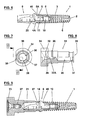
- Figures 1, 1A and 1B show a dental implant 1, preferably made of pure titanium, with the rounded apical end 2, the progressive, multiple thread 3, in this embodiment, a double-threaded, self-tapping thread extending from the apical end after another, widened cervical end 4 and what is followed by a micro-thread 5, also a multiple thread, eg a three-start thread.
- the micro-thread 5 adjoins the cervical end 4 towards a taper 5A and the implant has an inwardly directed chamfer 4A. Both measures allow a better growth of the bone and thus prevent its absorption and promote the growth of connective tissue at the cervical end of the implant. When using a construction with a curved step, the taper and bevel increase the effective biological width.
- the rounded apical end prevents the insertion of the dental implant largely injury of anatomical structures such as sinus floor, nasal floor, mandibular nerve or mucosa.
- the dental implant 1 also has a conical shape, which tapers towards the apical end 2, whereby the primary stability increases compared to a cylindrical dental implant shape when screwed into a straight cavity and leads to a perfect adaptation in the cervical region.
- the progressive multi-thread significantly improves the primary stability.
- a high mechanical primary stability is the most important prerequisite for the immediate or early loading of the dental implant.
- the progressive thread micro-movements of the inserted dental implant are largely prevented, thereby promoting its healing and the integration of the bone.
- the dental implant also has cutting grooves in the apical region 6, for example, two, which also serve as relief grooves for the bone chips.
- FIGS. 1A and 1B show that the dental implant has a hexagon socket 7 at the cervical end, followed by a threaded hole 8.
- Figures 2 and 3 show a structure 9, which is fastened by means of a retaining screw 10, see Fig. 4, to the dental implant.
- the structure is preferably also made of pure titanium and has a trained as a hexagon connection part 11 which fits into the hexagon socket 7 of the dental implant.
- This hexagon 11 is followed by a multi-functional post 12, which, starting from the connecting part, has a platform 13 and tapers from there to the end. Near the platform 13 is a circumferential groove 14 and along the post two opposing flats 15 are arranged.
- the groove in the cervical area of the post allows the use of a snap-on technique for different parts, which is easy to handle, very precise and time-saving. This applies in particular to the transfer, for the attachment of the provisional crown or for taking impressions with a multifunctional snap-on cap, see FIGS. 7 to 9.
- the groove serves to enable an optimum distribution of the cement at the onset of the final restoration ,
- the structure is formed as a sleeve and has a through hole with two different diameters. Seen from the cervical end 16, the diameter of the bore 17 is greater than that of the adjoining bore 18, thus forming a shoulder 19 on which the head of the retaining screw supported. At the cervical end, a hexagon socket 25 is arranged, by means of which the implant is screwed with the structure by a hexagon driver in the bone.
- the retaining screw 10 serves to fasten the structure to the dental implant and is designed accordingly.
- the retaining screw includes a head 20 with hexagon socket 21, a cylindrical part 22 and between a paragraph 23 and then to the cylindrical part a thread 24, which corresponds to the threaded hole 8 in the dental implant.
- a compilation of the dental implant with the structure it is apparent that the retaining screw 10 extends through the structure and can be screwed with a hexagon driver in the dental implant.
- the paragraph 23 of the retaining screw 10 is supported on the shoulder 19 of the structure, so that when tightening the retaining screw, the structure and the dental implant is contracted and secured.
- the two flats 15 of the post once serve to cement the crown against rotation and to achieve an axle-oriented positioning. This enables precise transfer.
- the posts are preferably coded by e.g. bicolor are marked to avoid confusion.
- the flat surfaces can be left unprocessed or undyed.
- the hexagon 11 and the hexagon socket 7 of the dental implant have a conicity of 0.5 ° -7 °.
- the biological width, the connective tissue cover at the cervical implant end, is 1.5 to 3.5 mm, according to Tarnow and other authors.
- the pre-prepared step 40 on the mounting portion of the assembly of about 1.7 to 2.1 mm, preferably 1.9 mm, above the dental implant end, takes into account this biological width of the soft tissues, which provides significant benefits for long-term success from an aesthetic and functional point of view. This effect is assisted by the taper 5A and taper 4A at the cervical end of the implant.
- the described construction with the post with a circumferential groove for a snap-on technique is not only advantageous for the implant 1 described above but also for other types of implants, in which case the connecting part must be designed entprechend and instead of a hexagon may have other coupling means.
- the closure screw 27 of FIG. 5 which has a countersunk head 28 with hexagon socket 29 and a thread 30 which fits into the thread 8 of the dental implant.
- this screw plug is screwed in at the rear part of a snap-on cap 31 in a corresponding recess 32 and secured by means of a cover 33.
- the snap-on cap allows the dentist and dental technician to work together to save time and precision.
- the snap-on cap has at its apical end 35 a bore 36 with constriction 37, which corresponds to the groove 14 of the body post.
- the snap-on cap can be snapped onto the mounting post to be securely fastened there.
- it has a bead 26 at its periphery.
- the snap-on cap In order for the snap-on cap to be used as a screwing aid, it must be held against rotation with respect to the mounting post. This is achieved in that the snap-on cap in the inner bore 36 has two opposing planar surfaces 38 which cooperate with the two flats 15 of the body post.
- the locking screw 27 is inserted in a receiving ring 34 of the cap, which has a flattening 39, which serves to secure a crown.
- FIGS. 10 to 12 show a transfer part 41 which can be connected directly to the implant 1 and not to the structure as in the previous example.
- the transfer part has at its apical end 42 a hexagon 43 which consists of two halves 43A and 43B, the halves being separated by a gap 43C, whereby they are resilient.
- This hexagon corresponds to the hexagon socket 7 of the implant and may also have a taper of 0.5 ° to 7 °.
- transfer part 41 corresponds to those of the snap-on cap 31 according to FIGS 7-9. This also applies to the inclusion of a closure screw 27.
- FIG. 12 the implant with the transfer part is shown partially cut away.
Landscapes
- Health & Medical Sciences (AREA)
- Animal Behavior & Ethology (AREA)
- Orthopedic Medicine & Surgery (AREA)
- Dentistry (AREA)
- Epidemiology (AREA)
- Life Sciences & Earth Sciences (AREA)
- Oral & Maxillofacial Surgery (AREA)
- General Health & Medical Sciences (AREA)
- Public Health (AREA)
- Veterinary Medicine (AREA)
- Dental Prosthetics (AREA)
- Materials For Medical Uses (AREA)
- Dental Preparations (AREA)
- Prostheses (AREA)
Abstract
Description
- Die vorliegende Erfindung bezieht sich auf ein Zahnimplantat, mit einem konischen Befestigungsteil mit einem Gewinde, das vom abgerundeten apikalen Ende ausgehend progressiv breiter wird. Ein solches Zahnimplantat ist aus der
US-B1-6 402 515 bekannt. Das dort offenbarte einfache, progressive Gewinde ist vorgesehen, das Anwachsen des Zahnimplantats im Knochen zu verbessern. - Aus der
WO-2004/098442 ist ein einschraubbares Zahnimplantat bekannt, bei dem auf ein relativ grobes Gewinde rillenförmige Vertiefungen eingeprägt sind, die in Richtung der Gewindegänge verlaufen und dort ein sogenanntes Mikrogewinde ergeben, um die Kontaktfläche zwischen Zahnimplantat und Knochengewebe zu vergrössern. Der Gewindestift selber ist im Wesentlichen zylindrisch und das Gewinde ist nicht progressiv ausgebildet. -
US-A-5 403 136 offenbart ein Zahnimplantat mit Schraubengewinde, das gegen das zervikale Ende ein Gewinde mit abnehmender Steigung aufweist. Der wesentliche Teil des Stiftes ist zylindrisch und am apikalen Ende eben ausgebildet. -
US-A1-2004/0006346 offenbart einen Zahnimplantatstift, der im Wesentlichen zylindrisch ausgebildet ist und ein ebenes apikales Ende aufweist. Der Stift weist zwei verschiedene Gewinde auf, ein relativ grobes Einfachgewinde sowie anschliessend ein sogenanntes Mikrogewinde, das hier als Dreifachgewinde ausgeführt ist. -
WO2004/103202 offenbart, wie das erstgenannte US-Patent, ein konisches Zahnimplantat mit einem progressiven Gewinde. - Es ist von diesem Stand der Technik ausgehend eine erste Aufgabe der vorliegenden Erfindung, ein Zahnimplantat zu schaffen, das in einer Kombination von verschiedenen Merkmalen minimalinvasives Einbringen, Gewebeschonung und gute Primärstabilität sowie gutes Anwachsen des Knochens gewährleistet. Diese Aufgabe wird mit dem Zahnimplantat gemäss Patentanspruch 1 gelöst.
- Es ist eine weitere Aufgabe der Erfindung, ein Zahnimplantat zu schaffen, das einfach und kostengünstig herzustellen ist und neben einer guten Verankerung einen Aufbau enthält, der die nachfolgenden Arbeitsgänge vereinfacht. Diese Aufgabe wird mit dem Zahnimplantat gemäss Patentanspruch 4 gelöst.
- Weitere Vorteile, wie z. B. eine gute Handhabung, sind in den abhängigen Ansprüchen definiert.
- Die Erfindung wird im Folgenden anhand von Zeichnungen von Ausführungsbeispielen näher erläutert werden.
- Fig. 1
- zeigt ein erfindungsgemässes Zahnimplantat in Draufsicht,
- Fig. 1A
- zeigt eine Ansicht von links der Fig. 1,
- Fig. 1B
- zeigt einen teilweisen Schnitt der Fig. 1,
- Fig. 2
- zeigt einen Aufbau für das Zahnimplantat von Fig. 1 in Frontansicht,
- Fig. 3
- zeigt den Aufbau gemäss dem Schnitt III - III in Fig. 2,
- Fig. 4
- zeigt eine Halteschraube,
- Fig. 5
- zeigt eine Verschlussschraube,
- Fig. 6
- zeigt einen mit dem Zahnimplantat verschraubten Aufbau,
- Fig. 7
- zeigt eine Snap-on-Kappe in Frontansicht,
- Fig. 8
- zeigt die Snap-on-Kappe gemäss der Linie VIII - VIII in Fig.7,
- Fig. 9
- zeigt ein versandfertiges, mit einem Aufbau zusammengesetztes Zahnimplantat und einer Snap-on-Kappe,
- Fig. 10
- zeigt eine Ausführungsvariante zur Ausführung gemäss Fig. 7, mit einem Transferteil in Frontansicht,
- Fig. 11
- zeigt das Transferteil gemäss der Linie XI - XI in Fig. 10, und
- Fig. 12
- zeigt ein versandfertiges Zahnimplantat mit einem Transferteil.
- Die Figuren 1, 1A und 1B zeigen ein Zahnimplantat 1, vorzugsweise aus reinem Titan gefertigt, mit dem abgerundeten apikalen Ende 2, dem progressiven, Mehrfachgewinde 3, in diesem Ausführungsbeispiel ein zweigängiges, selbstschneidendes Gewinde, das sich vom apikalen Ende her nach dem anderen, zervikalen Ende 4 hin verbreitert und woran sich ein Mikro-Gewinde 5 anschliesst, ebenfalls ein Mehrfachgewinde, z.B. ein dreigängiges Gewinde.
- Dem Mikrogewinde 5 schliesst sich zum zervikalen Ende 4 hin eine Verjüngung 5A an und das Implantat weist eine nach Innen gerichtete Abschrägung 4A auf. Beide Massnahmen ermöglichen ein besseres Anwachsen des Knochens und verhindern somit seine Resorption und fördern das Wachstum des Bindegewebes beim zervikalen Ende des Implantats. Bei der Verwendung eines Aufbaus mit einer gewölbten Stufe wird mit der Verjüngung und der Abschrägung die wirksame biologische Breite vergrössert.
- Das abgerundete apikale Ende verhindert beim Eindrehen des Zahnimplantates weitgehend die Verletzung anatomischer Strukturen wie Sinusboden, Nasenboden, Nervus mandibularus oder Schleimhaut.
- Das Zahnimplantat 1 weist ferner eine konische Form auf, die sich zum apikalen Ende 2 hin verjüngt, wodurch sich die Primärstabilität im Vergleich zu einer zylindrischen Zahnimplantatform beim Eindrehen in eine gerade Kavität erhöht und zu einer perfekten Adaption im zervikalen Bereich führt.
- Das progressive Mehrfachgewinde verbessert die Primärstabilität erheblich. Eine hohe mechanische Primärstabilität ist für die Sofort- bzw. Frühbelastung des Zahnimplantates die wichtigste Voraussetzung. Durch das progressive Gewinde werden Mikrobewegungen des inserierten Zahnimplantats weitgehend verhindert und dadurch dessen Einheilung und die Integration des Knochens gefördert.
- Im zervikalen Bereich geht das progressive Gewinde in ein Mehrfach-Mikrogewinde über, um in der Corticalis eine zu hohe Kompression und eine Nekrose zu vermeiden. Das Zahnimplantat weist ferner im apikalen Bereich Schneidnuten 6 auf, beispielsweise zwei, die auch als Entlastungsnuten für die Knochenspäne dienen.
- Aus den Figuren 1A und 1B geht hervor, dass das Zahnimplantat am zervikalen Ende einen Innensechskant 7 aufweist, dem sich eine Bohrung 8 mit Gewinde anschliesst.
- Die Figuren 2 und 3 zeigen einen Aufbau 9, der mittels einer Halteschraube 10, siehe Fig. 4, am Zahnimplantat befestigbar ist. Der Aufbau ist vorzugsweise auch aus Reintitan gefertigt und weist ein als Sechskant ausgebildetes Verbindungsteil 11 auf, der in den Innensechskant 7 des Zahnimplantats passt. Diesem Sechskant 11 schliesst sich ein multifunktionaler Pfosten 12 an, der, vom Verbindungsteil ausgehend, eine Plattform 13 aufweist und sich von dort zum Ende hin verjüngt. Nahe der Plattform 13 befindet sich eine umlaufende Rille 14 und längs des Pfostens sind zwei sich gegenüberliegende Abflachungen 15 angeordnet.
- Die Rille im zervikalen Bereich des Pfostens ermöglicht den Einsatz einer Snap-on-Technik für verschiedene Teile, die einfach zu handhaben, sehr präzise und zeitsparend ist. Dies gilt insbesondere für den Transfer, für die Befestigung der provisorischen Krone oder für die Abdrucknahme mit einer multifunktionalen Snap-on-Kappe, siehe Figuren 7 - 9. Ausserdem dient die Rille dazu, beim Einsetzen der endgültigen Versorgung eine optimale Verteilung des Befestigungszementes zu ermöglichen.
- Wie aus Fig. 2 hervorgeht, ist der Aufbau als Hülse ausgebildet und weist eine durchgehende Bohrung mit zwei verschiedenen Durchmessern auf. Vom zervikalen Ende 16 aus gesehen ist der Durchmesser der Bohrung 17 grösser als derjenige der anschliessenden Bohrung 18, womit ein Absatz 19 gebildet wird, auf dem sich der Kopf der Halteschraube abstützt. Am zervikalen Ende ist ein Innensechskant 25 angeordnet, mittels welchem das Implantat mit dem Aufbau durch einen Sechskantdreher in den Knochen eingedreht wird.
- Die Halteschraube 10 dient dazu, den Aufbau am Zahnimplantat zu befestigen und ist dementsprechend ausgebildet. In Fig. 4 von links nach rechts beschrieben enthält die Halteschraube einen Kopf 20 mit Innensechskant 21, ein zylindrisches Teil 22 und dazwischen einen Absatz 23 und anschliessend an den zylindrischen Teil ein Gewinde 24, das der Bohrung mit Gewinde 8 im Zahnimplantat entspricht.
- Aus Fig. 6, eine Zusammenstellung des Zahnimplantats mit dem Aufbau, geht hervor, dass sich die Halteschraube 10 durch den Aufbau hindurch erstreckt und mit einem Sechskantdreher in das Zahnimplantat eingeschraubt werden kann. Dabei stützt sich der Absatz 23 der Halteschraube 10 auf dem Absatz 19 des Aufbaus ab, so dass beim Eindrehen der Halteschraube der Aufbau und das Zahnimplantat zusammengezogen und gesichert wird.
- Wie aus der Zusammenstellung von Fig. 6 hervorgeht, besitzt der Aufbaupfosten 12 einen kleineren Durchmesser als das Zahnimplantat, um die Gewebeanlagerung von Weich- und Hartgewebe zu unterstützen und langfristig die Knochenresorption sowie die Infektionsgefahr zu verhindern. Der multifunktionale Pfosten 12 ist einheitlich für alle Zahnimplantate dieses Systems, auch bei unterschiedlichen Durchmessern zu verwenden und dient
- a) als Transferpfosten von der doppelt sterilen Verpackung in die vorgebohrte Kavität,
- b) zum Eindrehen in die vorgebohrte Kavität,
- c) als provisorischer Pfosten und
- d) als endgültiger Pfosten.
- Die beiden Abflachungen 15 des Pfostens dienen einmal dazu, die Krone verdrehsicher einzuzementieren und ein achsengerechtes Positionieren zu erreichen. Dadurch wird der präzise Transfer ermöglicht.
- Die Pfosten sind vorzugsweise kodiert, indem sie z.B. bicolor markiert sind, um Verwechslungen zu vermeiden. Dabei können die flachen Flächen unbearbeitet oder ungefärbt belassen werden.
- Um eine stabile Press-Fit-Passung zwischen Aufbau und Zahnimplantat zu erzielen, weist der Sechskant 11 und der Innensechskant 7 des Zahnimplantats eine Konizität von 0,5° - 7° auf. Dadurch wird auch eine exakte Übertragung ermöglicht, weil keine Wackelbewegungen auftreten können, die bei geraden Flächen wegen der notwendigen Toleranz unvermeidbar sind.
- Die biologische Breite, der Bindegewegüberzug beim zervikalen Implantatende, beträgt nach Tarnow und anderen Autoren 1,5 bis 3,5 mm. Die vorpräparierte Stufe 40 am Befestigungsteil des Aufbaus von etwa 1,7 bis 2,1 mm, vorzugsweise 1,9 mm, über dem Zahnimplantatende, berücksichtigt diese biologische Breite der Weichteile, was erhebliche Vorteile für den Langzeiterfolg aus ästhetischer und funktioneller Sicht bringt. Dieser Effekt wird durch die Verjüngung 5A und die Abschrägung 4A am zervikalen Implantatende unterstützt.
- Der beschriebene Aufbau mit dem Pfosten mit einer umlaufenden Rille für eine Snap-on Technik ist nicht nur für das Eingangs beschriebene Implantat 1 vorteilhaft sondern auch für andere Typen von Implantaten, wobei dann das Verbindungsteil entprechend ausgebildet sein muss und anstatt einen Sechskant andere Kopplungsmittel aufweisen kann.
- Falls das Zahnimplantat ohne Aufbau einwachsen soll ist es unerlässlich, seine Öffnung 7 und 8 zu verschliessen. Dazu dient die Verschlussschraube 27 von Fig. 5, die einen Versenkkopf 28 mit Innensechskant 29 und ein Gewinde 30 aufweist, das in das Gewinde 8 des Zahnimplantates passt.
- In der zum Versand fertigen Verpackung gemäss Fig. 9 ist diese Verschlussschraube am hinteren Teil einer Snap-on-Kappe 31 in einer entsprechenden Ausnehmung 32 eingedreht und mittels einer Abdeckung 33 gesichert.
- Die multifunktionale Snap-on-Kappe 31 ist aus einem ausbrennbaren Kunststoff gefertigt und kann, wie ihr Name aussagt, verschiedene Funktionen ausführen:
- a) Als Einbringhilfe für den Transfer aus der sterilen Verpackung in die vorgebohrte Kavität und zum Eindrehen von ein bis zwei Umdrehungen dienen.
- b) Als Basis für die provisorische Krone dienen, die exakt eingepasst werden kann. Die Befestigung der Krone erfolgt mittels der beschriebenen Snap-on-Technik und provisorischem Zement.
- c) Der exakten Übertragung als Abdruckkappe in Verbindung mit vorgefertigten Labor-Zahnimplantaten dienen. Die Form der Snap-on-Kappe ist auf den Pfosten des Aufbaus abgestimmt.
- d) Als vormodellierte Kronenbasis für den Zahntechniker und als Basis für die endgültige Versorgung dienen, nach dem der Techniker den Aufnahmering 34 weggefräst hat.
- Die Snap-on-Kappe ermöglicht in der Zusammenarbeit von Zahnarzt und Zahntechniker insgesamt einen ökonomischen Arbeitsablauf mit Zeitersparnis und hoher Präzision.
- Die Snap-on-Kappe weist an ihrem apikalen Ende 35 eine Bohrung 36 mit Einschnürung 37 auf, die der Rille 14 des Aufbaupfostens entspricht. Somit kann die Snap-on-Kappe auf den Aufbaupfosten aufgeschnappt werden, um dort sicher befestigt zu sein. Ausserdem weist sie an ihrem Umfang einen Wulst 26 auf.
- Damit die Snap-on-Kappe als Eindrehhilfe verwendet werden kann, muss sie gegenüber dem Aufbaupfosten drehsicher gehalten werden. Dies wird dadurch erreicht, dass die Snap-on-Kappe in der Innenbohrung 36 zwei sich gegenüberliegende ebene Flächen 38 aufweist, die mit den beiden Abflachungen 15 des Aufbaupfostens zusammenwirken.
- Die Verschlussschraube 27 ist in einem Aufnahmering 34 der Kappe eingesetzt, der eine Abflachung 39 aufweist, die der Sicherung einer Krone dient.
- In den Figuren 10 - 12 ist ein Transferteil 41 dargestellt, der direkt mit dem Implantat 1 verbunden werden kann und nicht mit dem Aufbau wie im vorhergehenden Beispiel. Dazu weist das Transferteil an seinem apikalen Ende 42 einen Sechskant 43 auf, der aus zwei Hälften 43A und 43B besteht, wobei die Hälften durch einen Spalt 43C getrennt sind, wodurch sie federnd sind. Dieser Sechskant entspricht dem Innensechskant 7 des Implantats und kann ebenfalls eine Konizität von 0,5° bis 7° aufweisen.
- Die übrigen Ausbildungen und Merkmale sowie Vorteile und Anwendungsmöglichkeiten des Transferteils 41 entsprechen denjenigen der Snap-on-Kappe 31 gemäss den Figuren 7-9. Dies gilt auch für die Aufnahme einer Verschlussschraube 27. In Figur 12 ist das Implantat mit dem Transferteil teilweise geschnitten eingezeichnet.
Claims (18)
- Zahnimplantat, mit einem konischen Schraubteil mit einem Gewinde, das vom abgerundeten apikalen Ende ausgehend progressiv breiter wird, dadurch gekennzeichnet, dass sich dem progressiven Mehrfachgewinde (3) ein Mehrfach-Mikrogewinde (15) mit kleinerer Steigung anschliesst.
- Zahnimplantat nach Anspruch 1, dadurch gekennzeichnet, dass es einen sich verjüngenden Innensechskant (7) aufweist, wobei die Konizität 0,5° bis 7° beträgt.
- Zahnimplantat nach Anspruch 1 oder 2, dadurch gekennzeichnet, dass sich dem Mikrogewinde (5) gegen das zervikale Ende (4) hin eine gegen die Mitte gerichtete Verjüngung (5A) anschliesst.
- Zahnimplantat nach einem der Ansprüche 1 bis 3, dadurch gekennzeichnet, dass das zervikale Ende (4) eine nach Innen gerichtete Abschrägung (4A) aufweist.
- Zahnimplantat nach einem der Ansprüche 1 bis 4 mit einen Aufbau, dadurch gekennzeichnet, dass der Aufbau (9) ein Verbindungsteil (11) und einen Pfosten (12) mit einer Rille (14) aufweist.
- Zahnimplantat nach Anspruch 5, dadurch gekennzeichnet, dass der Aufbau als Hülse ausgebildet ist und mittels einer Halteschraube (10) am Implantat befestigbar ist.
- Zahnimplantat nach Anspruch 6, dadurch gekennzeichnet, dass das Implantat eine Bohrung mit Gewinde (8) und die Halteschraube ein entsprechendes Gewinde (24) aufweist.
- Zahnimplantat nach einem der Ansprüche 5 bis 7, dadurch gekennzeichnet, dass das Verbindungsteil ein Sechskant (11) ist.
- Zahnimplantat nach einem der Ansprüche 5 bis 8, dadurch gekennzeichnet, dass das an den Sechskant (11) anschliessende gewölbte Teil (40) des Aufbaus bemessen ist, eine biologische Breite von ca. 2 mm zu erzeugen.
- Zahnimplantat nach einem der Ansprüche 5 bis 9, dadurch gekennzeichnet, dass der Pfosten (12) einen kleineren Durchmesser aufweist als das Zahnimplantat.
- Zahnimplantat nach einem der Ansprüche 5 bis 10, dadurch gekennzeichnet, dass der Pfosten (12) Abflachungen (15) aufweist.
- Zahnimplantat nach einem der Ansprüche 5 bis 11, dadurch gekennzeichnet, dass der Pfosten (12) an seinem zervikalen Ende (16) einen Innensechskant (25) aufweist.
- Zahnimplantat nach einem der Ansprüche 5 bis 12, dadurch gekennzeichnet, dass der Innensechskant (7) des Implantats und der Sechskant (11) des Aufbaus eine Konizität von 0,5° bis 7° aufweisen.
- Zahnimplantat mit Aufbau nach einem der Ansprüche 5 bis 13, mit einer multifunktionalen Snap-on-Kappe (31), die in der Rille (14) von Pfosten (12) eingeschnappt ist.
- Zahnimplantat nach Anspruch 14, dadurch gekennzeichnet, dass die Snap-on-Kappe am apikalen Ende (35) eine Bohrung (36) mit einem der Rille (14) am Pfosten (12) entsprechenden Innenwulst (37) und den Abflachungen (15) am Pfosten (12) entsprechenden Innenflächen (38) aufweist.
- Zahnimplantat nach einem der Ansprüche 1 bis 4, dadurch gekennzeichnet, dass daran ein Transferteil (41) angeordnet ist, wobei das Transferteil ein als Sechskant (43) ausgebildetes, in den Innensechskant (7) des Implantats steckbares Verbindungsteil aufweist.
- Zahnimplantat nach Anspruch 16, dadurch gekennzeichnet, dass der Sechskant (43) federnd ausgebildet ist und zwei Hälften (43A, 43B) sowie einen dazwischen angeordneten Spalt (43C) aufweist.
- Zahnimplantat nach einem der Ansprüche 14 bis 17, dadurch gekennzeichnet, dass die Snap-on-Kappe oder das Transferteil am zervikalen Ende eine verschliessbare Bohrung (32) zur Aufnahme einer Verschlussschraube (27) für das Implantat enthält.
Priority Applications (10)
| Application Number | Priority Date | Filing Date | Title |
|---|---|---|---|
| PL05405487T PL1757245T3 (pl) | 2005-08-22 | 2005-08-22 | Implant zęba |
| DE502005009966T DE502005009966D1 (de) | 2005-08-22 | 2005-08-22 | Zahnimplantat |
| EP05405487A EP1757245B1 (de) | 2005-08-22 | 2005-08-22 | Zahnimplantat |
| PT05405487T PT1757245E (pt) | 2005-08-22 | 2005-08-22 | Implante dentário |
| AT05405487T ATE474520T1 (de) | 2005-08-22 | 2005-08-22 | Zahnimplantat |
| DK05405487.9T DK1757245T3 (da) | 2005-08-22 | 2005-08-22 | Tandimplantat |
| KR1020087006935A KR20080036658A (ko) | 2005-08-22 | 2006-08-18 | 치아 임플란트 |
| RU2008105777/14A RU2426516C2 (ru) | 2005-08-22 | 2006-08-18 | Зубной имплантат |
| US12/064,590 US8632336B2 (en) | 2005-08-22 | 2006-08-18 | Tooth implant |
| PCT/CH2006/000439 WO2007022655A1 (de) | 2005-08-22 | 2006-08-18 | Zahnimplantat |
Applications Claiming Priority (1)
| Application Number | Priority Date | Filing Date | Title |
|---|---|---|---|
| EP05405487A EP1757245B1 (de) | 2005-08-22 | 2005-08-22 | Zahnimplantat |
Publications (2)
| Publication Number | Publication Date |
|---|---|
| EP1757245A1 true EP1757245A1 (de) | 2007-02-28 |
| EP1757245B1 EP1757245B1 (de) | 2010-07-21 |
Family
ID=35462447
Family Applications (1)
| Application Number | Title | Priority Date | Filing Date |
|---|---|---|---|
| EP05405487A Expired - Lifetime EP1757245B1 (de) | 2005-08-22 | 2005-08-22 | Zahnimplantat |
Country Status (10)
| Country | Link |
|---|---|
| US (1) | US8632336B2 (de) |
| EP (1) | EP1757245B1 (de) |
| KR (1) | KR20080036658A (de) |
| AT (1) | ATE474520T1 (de) |
| DE (1) | DE502005009966D1 (de) |
| DK (1) | DK1757245T3 (de) |
| PL (1) | PL1757245T3 (de) |
| PT (1) | PT1757245E (de) |
| RU (1) | RU2426516C2 (de) |
| WO (1) | WO2007022655A1 (de) |
Cited By (4)
| Publication number | Priority date | Publication date | Assignee | Title |
|---|---|---|---|---|
| ES2321573A1 (es) * | 2007-12-07 | 2009-06-08 | Juan Carlos Garcia Saban | Implante dental post-extraccion. |
| FR2942952A1 (fr) * | 2009-03-16 | 2010-09-17 | Gerard Scortecci | Implant dentaire a insertion axiale assurant une distraction crestale |
| WO2012126466A1 (de) * | 2011-03-22 | 2012-09-27 | Riemser Arzneimittel Ag | Zahnimplantat mit einem ersten konischen und einem zweiten zylindrischen schraubteil |
| EP2101676B1 (de) | 2006-12-14 | 2015-03-04 | Dentsply Implants Manufacturing GmbH | Anordnung zur insertion von implantaten |
Families Citing this family (25)
| Publication number | Priority date | Publication date | Assignee | Title |
|---|---|---|---|---|
| EP1757246A1 (de) * | 2005-08-22 | 2007-02-28 | Novident SA | Aufbau für ein Zahnimplantat |
| USD611511S1 (en) * | 2006-03-22 | 2010-03-09 | Bti, I+D, S.L. | Ridge expander drill |
| EP2231057A2 (de) | 2007-10-26 | 2010-09-29 | Council of Scientific & Industrial Research | Zahnimplantat |
| US20100151420A1 (en) * | 2008-12-11 | 2010-06-17 | Ranck Roger S | Fixtures for dental implants |
| US20100151423A1 (en) * | 2008-12-11 | 2010-06-17 | Ranck Roger S | Temporary restorations and related methods |
| US20100209877A1 (en) * | 2009-02-13 | 2010-08-19 | Stephen Hogan | Components for use with implants and related methods |
| US20100159421A1 (en) * | 2008-12-18 | 2010-06-24 | Sreenivas Koka | Dental Implant Component Placement and Fixation Device |
| KR101134342B1 (ko) * | 2010-04-22 | 2012-04-09 | 주식회사 메가젠임플란트 | 치과용 임플란트의 픽스츄어 및 그를 구비하는 임플란트 시술용 세트 |
| ES2798575T3 (es) * | 2010-05-05 | 2020-12-11 | Holger Zipprich | Implante dental |
| US20110306014A1 (en) * | 2010-06-11 | 2011-12-15 | Conte Gregory J | Components, Systems and Related Methods for Temporary Prosthetics |
| WO2012059908A1 (en) * | 2010-11-01 | 2012-05-10 | Ilya Mushayev | Multi-threaded dental implant |
| DE102010051176A1 (de) | 2010-11-15 | 2012-05-16 | Urs Brodbeck | Dental-Implantatsystem und Verfahren zur Herstellung eines Dental-Implantatsystems |
| DE102011009906A1 (de) | 2011-01-31 | 2012-08-02 | Holger Zipprich | Dental- Implantatsystem |
| WO2012115969A2 (en) | 2011-02-21 | 2012-08-30 | Aeton Medical Llc | Abutment and abutment systems for use with implants |
| EP2502600A1 (de) * | 2011-03-21 | 2012-09-26 | Biodenta Swiss AG | Dental-Implantatsystem |
| DE102011052644B4 (de) * | 2011-07-19 | 2013-05-29 | Zv3 - Zircon Vision Gmbh | Aufbauteil für einen künstlichen Zahnersatz, künstlicher Zahnersatz und Verfahren zur Herstellung und/oder Implantierung eines künstlichen Zahnersatzes |
| US8827702B2 (en) * | 2011-09-12 | 2014-09-09 | Cortex Dental Implant Industries, Ltd. | Driver and method |
| GB201212125D0 (en) | 2012-07-09 | 2012-08-22 | Nobel Biocare Services Ag | Abutment system and dental methods |
| WO2015026256A1 (ru) * | 2013-08-19 | 2015-02-26 | Sanisalov Evgenij Aleksandrovich | Стоматологический имплантат |
| BR102013027205B1 (pt) * | 2013-10-22 | 2020-10-27 | Jjgc Indústria E Comércio De Materiais Dentários S.A. | sistema de componente protético multifuncional |
| US10258434B1 (en) | 2017-05-14 | 2019-04-16 | Evollution IP Holding, Inc. | CIP for scanned and embedded low profile snap-in winged dual use dental impression post |
| CN107811716B (zh) * | 2017-12-06 | 2021-01-15 | 魏洪武 | 一种口腔种植体 |
| ES1220239Y (es) * | 2018-10-01 | 2019-02-07 | Terrats Medical S L | Pieza de capuchón para escaneado dental |
| CN110141382A (zh) * | 2019-05-29 | 2019-08-20 | 陕西科技大学 | 一种牙齿种植体及其种植方法 |
| KR102357622B1 (ko) * | 2021-05-21 | 2022-02-08 | 장현성 | 치과용 솔리드 어버트먼트 |
Citations (10)
| Publication number | Priority date | Publication date | Assignee | Title |
|---|---|---|---|---|
| US5403136A (en) | 1991-06-25 | 1995-04-04 | Synthes (U.S.A.) | Threaded fastener especially for orthopaedic purposes |
| US20020025505A1 (en) * | 1997-04-09 | 2002-02-28 | Beaty Keith D. | Implant delivery system |
| WO2002017814A1 (en) * | 2000-08-30 | 2002-03-07 | Nobel Biocare Ab | Impression cap |
| US6402515B1 (en) | 2001-01-10 | 2002-06-11 | Sulzer Dental Inc. | Dental implant with variable profile thread |
| US20040006346A1 (en) | 2001-08-15 | 2004-01-08 | Anders Holmen | Implant, arrangement comprising an implant, and method for inserting said implant in bone tissue |
| US20040101808A1 (en) * | 2002-11-13 | 2004-05-27 | Porter Stephan S. | Dental implant system |
| DE10315399A1 (de) * | 2003-02-21 | 2004-09-02 | Schröder, Ralf, Dr. | Zahnimplantat mit Grundkörper und Implantatpfosten sowie Grundkörper und Implantatpfosten für ein Zahnimplantat |
| US20040219488A1 (en) * | 2000-12-09 | 2004-11-04 | Young-Wook Choi | Dental implant and head for a compacttion drill |
| WO2004098442A1 (de) | 2003-05-03 | 2004-11-18 | Wolfgang Dinkelacker | Einschraubbares knochenimplantat |
| WO2004103202A1 (en) | 2003-05-21 | 2004-12-02 | Ophir Fromovich | Condensing skeletal implant that facilitate insertion |
Family Cites Families (36)
| Publication number | Priority date | Publication date | Assignee | Title |
|---|---|---|---|---|
| US82498A (en) * | 1868-09-29 | Improvement in automatic boiler-feeders | ||
| US4850870C1 (en) | 1987-10-23 | 2001-07-24 | Implant Innovations Inc | Prosthodontic restoration components |
| US5030095A (en) * | 1989-08-16 | 1991-07-09 | Niznick Gerald A | Angled abutment for endosseous implants |
| KR920010387B1 (ko) | 1990-07-14 | 1992-11-27 | 이종진 | 치아 임플랜트 |
| US5106300A (en) | 1990-09-26 | 1992-04-21 | Voitik Anton J | Dental implant attachment structure and method |
| GB9208442D0 (en) | 1992-04-16 | 1992-06-03 | Asher George B | Tooth & selection joint & jig(dental implants) |
| DE4342058A1 (de) | 1993-12-09 | 1995-06-22 | Eberle Medizintech Elemente | Enossales Einzelzahnimplantat |
| US6068479A (en) | 1995-02-21 | 2000-05-30 | Kwan; Norman Ho-Kwong | Dental implant system |
| US5829977A (en) | 1995-05-25 | 1998-11-03 | Implant Innovations, Inc. | Two-piece dental abutment |
| US5816809A (en) | 1995-09-20 | 1998-10-06 | Genetic Implant Systems, Inc. | Dental prosthesis support device and method of using same |
| DE19620394C1 (de) * | 1996-05-21 | 1997-09-18 | Degussa | Prothetischer Aufbaupfosten für Zahnimplantate |
| US5782918A (en) * | 1996-12-12 | 1998-07-21 | Folsom Metal Products | Implant abutment system |
| AUPO715197A0 (en) * | 1997-06-02 | 1997-06-26 | Behrend, Donald Albert | Occlusal registration coping system |
| US6168436B1 (en) | 1997-06-18 | 2001-01-02 | O'brien Gary | Universal dental implant abutment system |
| SE9702981D0 (sv) * | 1997-08-19 | 1997-08-19 | Astra Ab | Dental implant systems |
| GB2355051B (en) * | 1997-10-09 | 2002-02-27 | Nenad Sesic | Strain-inducing conical screw for stimulating bone transplant growth |
| US6159008A (en) * | 1998-07-13 | 2000-12-12 | Steri-Oss Inc. | Implant carrier with gripping fingers |
| SE9802571D0 (sv) * | 1998-07-17 | 1998-07-17 | Astra Ab | Implant |
| US6508650B2 (en) * | 1999-05-10 | 2003-01-21 | Neal B. Gittleman | Winged impression cap for reduced height dental impression post |
| US20070037123A1 (en) | 2000-10-26 | 2007-02-15 | Mansueto Robert F | High-strength dental-implant w/curvilinear-indexing and tool-free delivery-system |
| US6464500B1 (en) | 2001-05-22 | 2002-10-15 | Don Dragoljub Popovic | Dental implant and abutment system |
| US6824386B2 (en) * | 2001-11-01 | 2004-11-30 | Astra Tech Ab | Components for improved impression making |
| US6655961B2 (en) * | 2001-12-03 | 2003-12-02 | Richard Day Cottrell | Modified dental implant fixture |
| US6991461B2 (en) | 2001-12-28 | 2006-01-31 | Gittleman Neal B | Expandable dental implant apparatus |
| EP1474063B1 (de) | 2002-01-11 | 2009-04-22 | Nobel Biocare AB | Zahnimplantatseinbringungssystem |
| EP1626670A2 (de) | 2003-02-21 | 2006-02-22 | Ralf Schröder | Zahnimplantat mit grundkörper und implantatpfosten sowie grundkörper und implantatpfosten für ein zahnimplantat |
| AU2004220672A1 (en) | 2003-03-13 | 2004-09-23 | Young Ku Heo | Method for treating a screw-cement retained prosthesis, abutment and implant for a screw-cement retained prosthesis |
| PT1529498E (pt) * | 2003-11-05 | 2014-09-17 | Dentsply Implants Mfg Gmbh | Implante não metálico de várias peças |
| US20050233281A1 (en) | 2004-04-19 | 2005-10-20 | Gittleman Neal B | Uniquely positioned, winged, low profile impression cap for use with triple tray |
| US7632096B2 (en) | 2004-10-18 | 2009-12-15 | Gittleman Neal B | Rotating winged low profile impression transfer cap |
| US7677891B2 (en) * | 2005-02-01 | 2010-03-16 | Implant Direct Int'l, Inc. | Tapered endosseous dental implants with external multiple lead threads |
| US7785107B2 (en) | 2005-02-01 | 2010-08-31 | Niznick Gerald A | Multi-functional fixture mount |
| DE102005005402B4 (de) | 2005-02-05 | 2011-02-17 | Friadent Gmbh | Dentalimplantat sowie Implantatsystem |
| KR100696324B1 (ko) | 2005-07-15 | 2007-03-19 | 이석원 | 치과용 임플란트 장치 |
| EP1757246A1 (de) | 2005-08-22 | 2007-02-28 | Novident SA | Aufbau für ein Zahnimplantat |
| UA27037U (en) * | 2007-06-19 | 2007-10-10 | Dental implant |
-
2005
- 2005-08-22 DK DK05405487.9T patent/DK1757245T3/da active
- 2005-08-22 AT AT05405487T patent/ATE474520T1/de active
- 2005-08-22 PL PL05405487T patent/PL1757245T3/pl unknown
- 2005-08-22 PT PT05405487T patent/PT1757245E/pt unknown
- 2005-08-22 EP EP05405487A patent/EP1757245B1/de not_active Expired - Lifetime
- 2005-08-22 DE DE502005009966T patent/DE502005009966D1/de not_active Expired - Lifetime
-
2006
- 2006-08-18 US US12/064,590 patent/US8632336B2/en not_active Expired - Fee Related
- 2006-08-18 RU RU2008105777/14A patent/RU2426516C2/ru not_active IP Right Cessation
- 2006-08-18 KR KR1020087006935A patent/KR20080036658A/ko not_active Withdrawn
- 2006-08-18 WO PCT/CH2006/000439 patent/WO2007022655A1/de not_active Ceased
Patent Citations (10)
| Publication number | Priority date | Publication date | Assignee | Title |
|---|---|---|---|---|
| US5403136A (en) | 1991-06-25 | 1995-04-04 | Synthes (U.S.A.) | Threaded fastener especially for orthopaedic purposes |
| US20020025505A1 (en) * | 1997-04-09 | 2002-02-28 | Beaty Keith D. | Implant delivery system |
| WO2002017814A1 (en) * | 2000-08-30 | 2002-03-07 | Nobel Biocare Ab | Impression cap |
| US20040219488A1 (en) * | 2000-12-09 | 2004-11-04 | Young-Wook Choi | Dental implant and head for a compacttion drill |
| US6402515B1 (en) | 2001-01-10 | 2002-06-11 | Sulzer Dental Inc. | Dental implant with variable profile thread |
| US20040006346A1 (en) | 2001-08-15 | 2004-01-08 | Anders Holmen | Implant, arrangement comprising an implant, and method for inserting said implant in bone tissue |
| US20040101808A1 (en) * | 2002-11-13 | 2004-05-27 | Porter Stephan S. | Dental implant system |
| DE10315399A1 (de) * | 2003-02-21 | 2004-09-02 | Schröder, Ralf, Dr. | Zahnimplantat mit Grundkörper und Implantatpfosten sowie Grundkörper und Implantatpfosten für ein Zahnimplantat |
| WO2004098442A1 (de) | 2003-05-03 | 2004-11-18 | Wolfgang Dinkelacker | Einschraubbares knochenimplantat |
| WO2004103202A1 (en) | 2003-05-21 | 2004-12-02 | Ophir Fromovich | Condensing skeletal implant that facilitate insertion |
Cited By (11)
| Publication number | Priority date | Publication date | Assignee | Title |
|---|---|---|---|---|
| EP2101676B1 (de) | 2006-12-14 | 2015-03-04 | Dentsply Implants Manufacturing GmbH | Anordnung zur insertion von implantaten |
| ES2321573A1 (es) * | 2007-12-07 | 2009-06-08 | Juan Carlos Garcia Saban | Implante dental post-extraccion. |
| WO2009071712A1 (es) * | 2007-12-07 | 2009-06-11 | Juan Carlos Garcia Saban | Implante dental post - extracción |
| ES2321573B1 (es) * | 2007-12-07 | 2010-03-26 | Juan Carlos Garcia Saban | Implante dental post-extraccion. |
| CN101909543A (zh) * | 2007-12-07 | 2010-12-08 | J·C·加西亚萨万 | 拔牙后的牙齿植入件 |
| JP2011505884A (ja) * | 2007-12-07 | 2011-03-03 | サバン フアン カルロス ガルシア | 抜歯後歯科インプラント |
| RU2459594C2 (ru) * | 2007-12-07 | 2012-08-27 | САБАН Хуан Карлос ГАРСИЯ | Постэкстракционный дентальный имплантат |
| FR2942952A1 (fr) * | 2009-03-16 | 2010-09-17 | Gerard Scortecci | Implant dentaire a insertion axiale assurant une distraction crestale |
| WO2010105965A1 (en) * | 2009-03-16 | 2010-09-23 | Scortecci Gerard | Dental implant for axial insertion to provide a crestal distraction |
| WO2012126466A1 (de) * | 2011-03-22 | 2012-09-27 | Riemser Arzneimittel Ag | Zahnimplantat mit einem ersten konischen und einem zweiten zylindrischen schraubteil |
| EP2688512A1 (de) * | 2011-03-22 | 2014-01-29 | RIEMSER Pharma GmbH | Zahnimplantat mit einem ersten konischen und einem zweiten zylindrischen schraubteil |
Also Published As
| Publication number | Publication date |
|---|---|
| ATE474520T1 (de) | 2010-08-15 |
| US8632336B2 (en) | 2014-01-21 |
| RU2426516C2 (ru) | 2011-08-20 |
| DE502005009966D1 (de) | 2010-09-02 |
| PT1757245E (pt) | 2010-10-21 |
| US20080241792A1 (en) | 2008-10-02 |
| DK1757245T3 (da) | 2010-11-15 |
| RU2008105777A (ru) | 2009-09-27 |
| KR20080036658A (ko) | 2008-04-28 |
| WO2007022655A1 (de) | 2007-03-01 |
| EP1757245B1 (de) | 2010-07-21 |
| PL1757245T3 (pl) | 2011-01-31 |
Similar Documents
| Publication | Publication Date | Title |
|---|---|---|
| EP1757245B1 (de) | Zahnimplantat | |
| EP1757246A1 (de) | Aufbau für ein Zahnimplantat | |
| DE69115931T2 (de) | Vorrichtung sowie verfahren zum befestigen eines elements beim ersatz eines teils eines gebisses | |
| DE69828587T2 (de) | Knochen- verankerungselement | |
| DE102010055433B4 (de) | Knochenschraube und Vorrichtung zur Knochendistraktion | |
| EP2667820B1 (de) | Zahnersatz-system | |
| DE60002235T2 (de) | Vorrichtung für ein enossales Zahnimplantat | |
| DE20122337U1 (de) | Distraktionsvorrichtung | |
| DE10260222A1 (de) | Rohrförmiges Element für ein in der Wirbelsäulen- oder der Knochenchirurgie zu verwendendes Implantat und Implantat mit einem solchen Element | |
| EP0438048A1 (de) | Dentalimplantat | |
| DE2540077A1 (de) | Implantierbare vorrichtung | |
| EP2364124A1 (de) | Dentalimplantat zur insertion in einen kieferknochen und zum befestigen von zahnersatz | |
| EP1850784B1 (de) | Zahnimplantat | |
| EP2674127B1 (de) | Implantat | |
| DE102005006979A1 (de) | Keramisches enossales Zahnimplantat | |
| DE69830407T2 (de) | Implantatsystem | |
| EP3542751A1 (de) | Dentalimplantatsystem | |
| CH696800A5 (de) | Implantat zum Halten und /oder Bilden eines Zahnersatzes und verschiedene Zubehörteile zu einem Implantat. | |
| EP0786975B1 (de) | Implantat-system für extra-orale applikationen und die orthodontie | |
| DE102007046879B4 (de) | Dentalimplantat | |
| EP1462066B1 (de) | Kieferimplantat mit abgewinkeltem Pfostenverlauf | |
| EP3386426B1 (de) | Dentalimplantatsystem | |
| EP3777755A1 (de) | Dentalimplantat und dentalimplantatsystem | |
| DE10356920A1 (de) | In einen menschlichen Kiefer endostal einschraubbares Dentalimplantat zur Aufnahme und Fixierung eines Zahnersatzes | |
| EP1440670A1 (de) | Temporärer Aufsatz für Kieferimplantate |
Legal Events
| Date | Code | Title | Description |
|---|---|---|---|
| PUAI | Public reference made under article 153(3) epc to a published international application that has entered the european phase |
Free format text: ORIGINAL CODE: 0009012 |
|
| AK | Designated contracting states |
Kind code of ref document: A1 Designated state(s): AT BE BG CH CY CZ DE DK EE ES FI FR GB GR HU IE IS IT LI LT LU LV MC NL PL PT RO SE SI SK TR |
|
| AX | Request for extension of the european patent |
Extension state: AL BA HR MK YU |
|
| RAP1 | Party data changed (applicant data changed or rights of an application transferred) |
Owner name: CURASAN AG |
|
| RIN1 | Information on inventor provided before grant (corrected) |
Inventor name: PETERS, FABIAN Inventor name: ROESSLER, HANS-DIETER |
|
| 17P | Request for examination filed |
Effective date: 20070823 |
|
| 17Q | First examination report despatched |
Effective date: 20070924 |
|
| AKX | Designation fees paid |
Designated state(s): AT BE BG CH CY CZ DE DK EE ES FI FR GB GR HU IE IS IT LI LT LU LV MC NL PL PT RO SE SI SK TR |
|
| RAP1 | Party data changed (applicant data changed or rights of an application transferred) |
Owner name: RIEMSER ARZNEIMITTEL AG |
|
| GRAP | Despatch of communication of intention to grant a patent |
Free format text: ORIGINAL CODE: EPIDOSNIGR1 |
|
| GRAS | Grant fee paid |
Free format text: ORIGINAL CODE: EPIDOSNIGR3 |
|
| GRAA | (expected) grant |
Free format text: ORIGINAL CODE: 0009210 |
|
| AK | Designated contracting states |
Kind code of ref document: B1 Designated state(s): AT BE BG CH CY CZ DE DK EE ES FI FR GB GR HU IE IS IT LI LT LU LV MC NL PL PT RO SE SI SK TR |
|
| REG | Reference to a national code |
Ref country code: GB Ref legal event code: FG4D Free format text: NOT ENGLISH |
|
| REG | Reference to a national code |
Ref country code: CH Ref legal event code: EP |
|
| REG | Reference to a national code |
Ref country code: IE Ref legal event code: FG4D |
|
| REF | Corresponds to: |
Ref document number: 502005009966 Country of ref document: DE Date of ref document: 20100902 Kind code of ref document: P |
|
| REG | Reference to a national code |
Ref country code: CH Ref legal event code: NV Representative=s name: AMMANN PATENTANWAELTE AG BERN |
|
| REG | Reference to a national code |
Ref country code: DK Ref legal event code: T3 |
|
| REG | Reference to a national code |
Ref country code: NL Ref legal event code: VDEP Effective date: 20100721 |
|
| LTIE | Lt: invalidation of european patent or patent extension |
Effective date: 20100721 |
|
| PG25 | Lapsed in a contracting state [announced via postgrant information from national office to epo] |
Ref country code: NL Free format text: LAPSE BECAUSE OF FAILURE TO SUBMIT A TRANSLATION OF THE DESCRIPTION OR TO PAY THE FEE WITHIN THE PRESCRIBED TIME-LIMIT Effective date: 20100721 Ref country code: FI Free format text: LAPSE BECAUSE OF FAILURE TO SUBMIT A TRANSLATION OF THE DESCRIPTION OR TO PAY THE FEE WITHIN THE PRESCRIBED TIME-LIMIT Effective date: 20100721 Ref country code: LT Free format text: LAPSE BECAUSE OF FAILURE TO SUBMIT A TRANSLATION OF THE DESCRIPTION OR TO PAY THE FEE WITHIN THE PRESCRIBED TIME-LIMIT Effective date: 20100721 |
|
| REG | Reference to a national code |
Ref country code: PL Ref legal event code: T3 |
|
| REG | Reference to a national code |
Ref country code: IE Ref legal event code: FD4D |
|
| BERE | Be: lapsed |
Owner name: RIEMSER ARZNEIMITTEL A.G. Effective date: 20100831 |
|
| PG25 | Lapsed in a contracting state [announced via postgrant information from national office to epo] |
Ref country code: SI Free format text: LAPSE BECAUSE OF FAILURE TO SUBMIT A TRANSLATION OF THE DESCRIPTION OR TO PAY THE FEE WITHIN THE PRESCRIBED TIME-LIMIT Effective date: 20100721 Ref country code: IS Free format text: LAPSE BECAUSE OF FAILURE TO SUBMIT A TRANSLATION OF THE DESCRIPTION OR TO PAY THE FEE WITHIN THE PRESCRIBED TIME-LIMIT Effective date: 20101121 Ref country code: CY Free format text: LAPSE BECAUSE OF FAILURE TO SUBMIT A TRANSLATION OF THE DESCRIPTION OR TO PAY THE FEE WITHIN THE PRESCRIBED TIME-LIMIT Effective date: 20100721 Ref country code: BG Free format text: LAPSE BECAUSE OF FAILURE TO SUBMIT A TRANSLATION OF THE DESCRIPTION OR TO PAY THE FEE WITHIN THE PRESCRIBED TIME-LIMIT Effective date: 20101021 |
|
| PG25 | Lapsed in a contracting state [announced via postgrant information from national office to epo] |
Ref country code: LV Free format text: LAPSE BECAUSE OF FAILURE TO SUBMIT A TRANSLATION OF THE DESCRIPTION OR TO PAY THE FEE WITHIN THE PRESCRIBED TIME-LIMIT Effective date: 20100721 Ref country code: SE Free format text: LAPSE BECAUSE OF FAILURE TO SUBMIT A TRANSLATION OF THE DESCRIPTION OR TO PAY THE FEE WITHIN THE PRESCRIBED TIME-LIMIT Effective date: 20100721 Ref country code: GR Free format text: LAPSE BECAUSE OF FAILURE TO SUBMIT A TRANSLATION OF THE DESCRIPTION OR TO PAY THE FEE WITHIN THE PRESCRIBED TIME-LIMIT Effective date: 20101022 Ref country code: MC Free format text: LAPSE BECAUSE OF NON-PAYMENT OF DUE FEES Effective date: 20100831 |
|
| PG25 | Lapsed in a contracting state [announced via postgrant information from national office to epo] |
Ref country code: IE Free format text: LAPSE BECAUSE OF FAILURE TO SUBMIT A TRANSLATION OF THE DESCRIPTION OR TO PAY THE FEE WITHIN THE PRESCRIBED TIME-LIMIT Effective date: 20100721 |
|
| PLBE | No opposition filed within time limit |
Free format text: ORIGINAL CODE: 0009261 |
|
| STAA | Information on the status of an ep patent application or granted ep patent |
Free format text: STATUS: NO OPPOSITION FILED WITHIN TIME LIMIT |
|
| PG25 | Lapsed in a contracting state [announced via postgrant information from national office to epo] |
Ref country code: IT Free format text: LAPSE BECAUSE OF FAILURE TO SUBMIT A TRANSLATION OF THE DESCRIPTION OR TO PAY THE FEE WITHIN THE PRESCRIBED TIME-LIMIT Effective date: 20100721 Ref country code: RO Free format text: LAPSE BECAUSE OF FAILURE TO SUBMIT A TRANSLATION OF THE DESCRIPTION OR TO PAY THE FEE WITHIN THE PRESCRIBED TIME-LIMIT Effective date: 20100721 Ref country code: CZ Free format text: LAPSE BECAUSE OF FAILURE TO SUBMIT A TRANSLATION OF THE DESCRIPTION OR TO PAY THE FEE WITHIN THE PRESCRIBED TIME-LIMIT Effective date: 20100721 Ref country code: SK Free format text: LAPSE BECAUSE OF FAILURE TO SUBMIT A TRANSLATION OF THE DESCRIPTION OR TO PAY THE FEE WITHIN THE PRESCRIBED TIME-LIMIT Effective date: 20100721 Ref country code: EE Free format text: LAPSE BECAUSE OF FAILURE TO SUBMIT A TRANSLATION OF THE DESCRIPTION OR TO PAY THE FEE WITHIN THE PRESCRIBED TIME-LIMIT Effective date: 20100721 |
|
| 26N | No opposition filed |
Effective date: 20110426 |
|
| PG25 | Lapsed in a contracting state [announced via postgrant information from national office to epo] |
Ref country code: BE Free format text: LAPSE BECAUSE OF NON-PAYMENT OF DUE FEES Effective date: 20100831 |
|
| REG | Reference to a national code |
Ref country code: DE Ref legal event code: R097 Ref document number: 502005009966 Country of ref document: DE Effective date: 20110426 |
|
| PG25 | Lapsed in a contracting state [announced via postgrant information from national office to epo] |
Ref country code: LU Free format text: LAPSE BECAUSE OF NON-PAYMENT OF DUE FEES Effective date: 20100822 Ref country code: HU Free format text: LAPSE BECAUSE OF FAILURE TO SUBMIT A TRANSLATION OF THE DESCRIPTION OR TO PAY THE FEE WITHIN THE PRESCRIBED TIME-LIMIT Effective date: 20110122 |
|
| PG25 | Lapsed in a contracting state [announced via postgrant information from national office to epo] |
Ref country code: TR Free format text: LAPSE BECAUSE OF FAILURE TO SUBMIT A TRANSLATION OF THE DESCRIPTION OR TO PAY THE FEE WITHIN THE PRESCRIBED TIME-LIMIT Effective date: 20100721 |
|
| REG | Reference to a national code |
Ref country code: CH Ref legal event code: PUE Owner name: RIEMSER PHARMA GMBH, DE Free format text: FORMER OWNER: RIEMSER ARZNEIMITTEL AG, DE |
|
| REG | Reference to a national code |
Ref country code: DE Ref legal event code: R082 Ref document number: 502005009966 Country of ref document: DE Representative=s name: HERTIN ANWALTSSOZIETAET, DE Effective date: 20130124 Ref country code: PT Ref legal event code: PC4A Owner name: RIEMSER PHARMA GMBH, DE Effective date: 20130306 Ref country code: DE Ref legal event code: R082 Ref document number: 502005009966 Country of ref document: DE Representative=s name: HERTIN UND PARTNER RECHTS- UND PATENTANWAELTE, DE Effective date: 20130124 Ref country code: DE Ref legal event code: R082 Ref document number: 502005009966 Country of ref document: DE Representative=s name: HERTIN & PARTNER RECHTS- UND PATENTANWAELTE PA, DE Effective date: 20130124 Ref country code: DE Ref legal event code: R081 Ref document number: 502005009966 Country of ref document: DE Owner name: RIEMSER PHARMA GMBH, DE Free format text: FORMER OWNER: RIEMSER ARZNEIMITTEL AG, 17493 GREIFSWALD, DE Effective date: 20130124 |
|
| REG | Reference to a national code |
Ref country code: FR Ref legal event code: TP Owner name: RIEMSER PHARMA GMBH, DE Effective date: 20130610 |
|
| REG | Reference to a national code |
Ref country code: ES Ref legal event code: PC2A Owner name: RIEMSER PHARMA GMBH Effective date: 20130710 |
|
| REG | Reference to a national code |
Ref country code: GB Ref legal event code: 732E Free format text: REGISTERED BETWEEN 20130711 AND 20130717 |
|
| REG | Reference to a national code |
Ref country code: CH Ref legal event code: NV Representative=s name: AMMANN PATENTANWAELTE AG BERN, CH |
|
| REG | Reference to a national code |
Ref country code: AT Ref legal event code: PC Ref document number: 474520 Country of ref document: AT Kind code of ref document: T Owner name: RIEMSER PHARMA GMBH, DE Effective date: 20140409 |
|
| PGFP | Annual fee paid to national office [announced via postgrant information from national office to epo] |
Ref country code: DE Payment date: 20140827 Year of fee payment: 10 Ref country code: CH Payment date: 20140827 Year of fee payment: 10 Ref country code: DK Payment date: 20140819 Year of fee payment: 10 |
|
| PGFP | Annual fee paid to national office [announced via postgrant information from national office to epo] |
Ref country code: FR Payment date: 20140814 Year of fee payment: 10 Ref country code: ES Payment date: 20140812 Year of fee payment: 10 Ref country code: GB Payment date: 20140801 Year of fee payment: 10 Ref country code: PL Payment date: 20140721 Year of fee payment: 10 Ref country code: AT Payment date: 20140829 Year of fee payment: 10 |
|
| PGFP | Annual fee paid to national office [announced via postgrant information from national office to epo] |
Ref country code: PT Payment date: 20140224 Year of fee payment: 10 |
|
| REG | Reference to a national code |
Ref country code: PT Ref legal event code: MM4A Free format text: LAPSE DUE TO NON-PAYMENT OF FEES Effective date: 20160222 Ref country code: DE Ref legal event code: R119 Ref document number: 502005009966 Country of ref document: DE |
|
| REG | Reference to a national code |
Ref country code: DK Ref legal event code: EBP Effective date: 20150831 |
|
| REG | Reference to a national code |
Ref country code: CH Ref legal event code: PL |
|
| REG | Reference to a national code |
Ref country code: AT Ref legal event code: MM01 Ref document number: 474520 Country of ref document: AT Kind code of ref document: T Effective date: 20150822 |
|
| GBPC | Gb: european patent ceased through non-payment of renewal fee |
Effective date: 20150822 |
|
| PG25 | Lapsed in a contracting state [announced via postgrant information from national office to epo] |
Ref country code: LI Free format text: LAPSE BECAUSE OF NON-PAYMENT OF DUE FEES Effective date: 20150831 Ref country code: CH Free format text: LAPSE BECAUSE OF NON-PAYMENT OF DUE FEES Effective date: 20150831 |
|
| PG25 | Lapsed in a contracting state [announced via postgrant information from national office to epo] |
Ref country code: PT Free format text: LAPSE BECAUSE OF NON-PAYMENT OF DUE FEES Effective date: 20160222 Ref country code: AT Free format text: LAPSE BECAUSE OF NON-PAYMENT OF DUE FEES Effective date: 20150822 |
|
| REG | Reference to a national code |
Ref country code: FR Ref legal event code: ST Effective date: 20160429 |
|
| PG25 | Lapsed in a contracting state [announced via postgrant information from national office to epo] |
Ref country code: GB Free format text: LAPSE BECAUSE OF NON-PAYMENT OF DUE FEES Effective date: 20150822 Ref country code: DE Free format text: LAPSE BECAUSE OF NON-PAYMENT OF DUE FEES Effective date: 20160301 |
|
| PG25 | Lapsed in a contracting state [announced via postgrant information from national office to epo] |
Ref country code: DK Free format text: LAPSE BECAUSE OF NON-PAYMENT OF DUE FEES Effective date: 20150831 Ref country code: FR Free format text: LAPSE BECAUSE OF NON-PAYMENT OF DUE FEES Effective date: 20150831 |
|
| REG | Reference to a national code |
Ref country code: ES Ref legal event code: FD2A Effective date: 20160927 |
|
| PG25 | Lapsed in a contracting state [announced via postgrant information from national office to epo] |
Ref country code: PL Free format text: LAPSE BECAUSE OF NON-PAYMENT OF DUE FEES Effective date: 20150822 |
|
| PG25 | Lapsed in a contracting state [announced via postgrant information from national office to epo] |
Ref country code: ES Free format text: LAPSE BECAUSE OF NON-PAYMENT OF DUE FEES Effective date: 20150823 |