EP1756544B1 - Dispositifs de diagnostic intégrant des éléments fluidiques et procédés de fabrication - Google Patents
Dispositifs de diagnostic intégrant des éléments fluidiques et procédés de fabrication Download PDFInfo
- Publication number
- EP1756544B1 EP1756544B1 EP05749838.8A EP05749838A EP1756544B1 EP 1756544 B1 EP1756544 B1 EP 1756544B1 EP 05749838 A EP05749838 A EP 05749838A EP 1756544 B1 EP1756544 B1 EP 1756544B1
- Authority
- EP
- European Patent Office
- Prior art keywords
- chamber
- card
- fluid
- valve
- module
- Prior art date
- Legal status (The legal status is an assumption and is not a legal conclusion. Google has not performed a legal analysis and makes no representation as to the accuracy of the status listed.)
- Active
Links
Images


Classifications
-
- G—PHYSICS
- G01—MEASURING; TESTING
- G01N—INVESTIGATING OR ANALYSING MATERIALS BY DETERMINING THEIR CHEMICAL OR PHYSICAL PROPERTIES
- G01N27/00—Investigating or analysing materials by the use of electric, electrochemical, or magnetic means
- G01N27/26—Investigating or analysing materials by the use of electric, electrochemical, or magnetic means by investigating electrochemical variables; by using electrolysis or electrophoresis
-
- B—PERFORMING OPERATIONS; TRANSPORTING
- B01—PHYSICAL OR CHEMICAL PROCESSES OR APPARATUS IN GENERAL
- B01L—CHEMICAL OR PHYSICAL LABORATORY APPARATUS FOR GENERAL USE
- B01L3/00—Containers or dishes for laboratory use, e.g. laboratory glassware; Droppers
- B01L3/50—Containers for the purpose of retaining a material to be analysed, e.g. test tubes
- B01L3/502—Containers for the purpose of retaining a material to be analysed, e.g. test tubes with fluid transport, e.g. in multi-compartment structures
- B01L3/5027—Containers for the purpose of retaining a material to be analysed, e.g. test tubes with fluid transport, e.g. in multi-compartment structures by integrated microfluidic structures, i.e. dimensions of channels and chambers are such that surface tension forces are important, e.g. lab-on-a-chip
- B01L3/502707—Containers for the purpose of retaining a material to be analysed, e.g. test tubes with fluid transport, e.g. in multi-compartment structures by integrated microfluidic structures, i.e. dimensions of channels and chambers are such that surface tension forces are important, e.g. lab-on-a-chip characterised by the manufacture of the container or its components
-
- B—PERFORMING OPERATIONS; TRANSPORTING
- B01—PHYSICAL OR CHEMICAL PROCESSES OR APPARATUS IN GENERAL
- B01L—CHEMICAL OR PHYSICAL LABORATORY APPARATUS FOR GENERAL USE
- B01L3/00—Containers or dishes for laboratory use, e.g. laboratory glassware; Droppers
- B01L3/50—Containers for the purpose of retaining a material to be analysed, e.g. test tubes
- B01L3/502—Containers for the purpose of retaining a material to be analysed, e.g. test tubes with fluid transport, e.g. in multi-compartment structures
- B01L3/5027—Containers for the purpose of retaining a material to be analysed, e.g. test tubes with fluid transport, e.g. in multi-compartment structures by integrated microfluidic structures, i.e. dimensions of channels and chambers are such that surface tension forces are important, e.g. lab-on-a-chip
- B01L3/502715—Containers for the purpose of retaining a material to be analysed, e.g. test tubes with fluid transport, e.g. in multi-compartment structures by integrated microfluidic structures, i.e. dimensions of channels and chambers are such that surface tension forces are important, e.g. lab-on-a-chip characterised by interfacing components, e.g. fluidic, electrical, optical or mechanical interfaces
-
- B—PERFORMING OPERATIONS; TRANSPORTING
- B01—PHYSICAL OR CHEMICAL PROCESSES OR APPARATUS IN GENERAL
- B01L—CHEMICAL OR PHYSICAL LABORATORY APPARATUS FOR GENERAL USE
- B01L3/00—Containers or dishes for laboratory use, e.g. laboratory glassware; Droppers
- B01L3/50—Containers for the purpose of retaining a material to be analysed, e.g. test tubes
- B01L3/502—Containers for the purpose of retaining a material to be analysed, e.g. test tubes with fluid transport, e.g. in multi-compartment structures
- B01L3/5027—Containers for the purpose of retaining a material to be analysed, e.g. test tubes with fluid transport, e.g. in multi-compartment structures by integrated microfluidic structures, i.e. dimensions of channels and chambers are such that surface tension forces are important, e.g. lab-on-a-chip
- B01L3/502723—Containers for the purpose of retaining a material to be analysed, e.g. test tubes with fluid transport, e.g. in multi-compartment structures by integrated microfluidic structures, i.e. dimensions of channels and chambers are such that surface tension forces are important, e.g. lab-on-a-chip characterised by venting arrangements
-
- B—PERFORMING OPERATIONS; TRANSPORTING
- B01—PHYSICAL OR CHEMICAL PROCESSES OR APPARATUS IN GENERAL
- B01L—CHEMICAL OR PHYSICAL LABORATORY APPARATUS FOR GENERAL USE
- B01L3/00—Containers or dishes for laboratory use, e.g. laboratory glassware; Droppers
- B01L3/50—Containers for the purpose of retaining a material to be analysed, e.g. test tubes
- B01L3/502—Containers for the purpose of retaining a material to be analysed, e.g. test tubes with fluid transport, e.g. in multi-compartment structures
- B01L3/5027—Containers for the purpose of retaining a material to be analysed, e.g. test tubes with fluid transport, e.g. in multi-compartment structures by integrated microfluidic structures, i.e. dimensions of channels and chambers are such that surface tension forces are important, e.g. lab-on-a-chip
- B01L3/50273—Containers for the purpose of retaining a material to be analysed, e.g. test tubes with fluid transport, e.g. in multi-compartment structures by integrated microfluidic structures, i.e. dimensions of channels and chambers are such that surface tension forces are important, e.g. lab-on-a-chip characterised by the means or forces applied to move the fluids
-
- B—PERFORMING OPERATIONS; TRANSPORTING
- B01—PHYSICAL OR CHEMICAL PROCESSES OR APPARATUS IN GENERAL
- B01L—CHEMICAL OR PHYSICAL LABORATORY APPARATUS FOR GENERAL USE
- B01L3/00—Containers or dishes for laboratory use, e.g. laboratory glassware; Droppers
- B01L3/50—Containers for the purpose of retaining a material to be analysed, e.g. test tubes
- B01L3/502—Containers for the purpose of retaining a material to be analysed, e.g. test tubes with fluid transport, e.g. in multi-compartment structures
- B01L3/5027—Containers for the purpose of retaining a material to be analysed, e.g. test tubes with fluid transport, e.g. in multi-compartment structures by integrated microfluidic structures, i.e. dimensions of channels and chambers are such that surface tension forces are important, e.g. lab-on-a-chip
- B01L3/502738—Containers for the purpose of retaining a material to be analysed, e.g. test tubes with fluid transport, e.g. in multi-compartment structures by integrated microfluidic structures, i.e. dimensions of channels and chambers are such that surface tension forces are important, e.g. lab-on-a-chip characterised by integrated valves
-
- B—PERFORMING OPERATIONS; TRANSPORTING
- B01—PHYSICAL OR CHEMICAL PROCESSES OR APPARATUS IN GENERAL
- B01L—CHEMICAL OR PHYSICAL LABORATORY APPARATUS FOR GENERAL USE
- B01L7/00—Heating or cooling apparatus; Heat insulating devices
-
- B—PERFORMING OPERATIONS; TRANSPORTING
- B32—LAYERED PRODUCTS
- B32B—LAYERED PRODUCTS, i.e. PRODUCTS BUILT-UP OF STRATA OF FLAT OR NON-FLAT, e.g. CELLULAR OR HONEYCOMB, FORM
- B32B37/00—Methods or apparatus for laminating, e.g. by curing or by ultrasonic bonding
- B32B37/06—Methods or apparatus for laminating, e.g. by curing or by ultrasonic bonding characterised by the heating method
-
- B—PERFORMING OPERATIONS; TRANSPORTING
- B32—LAYERED PRODUCTS
- B32B—LAYERED PRODUCTS, i.e. PRODUCTS BUILT-UP OF STRATA OF FLAT OR NON-FLAT, e.g. CELLULAR OR HONEYCOMB, FORM
- B32B37/00—Methods or apparatus for laminating, e.g. by curing or by ultrasonic bonding
- B32B37/10—Methods or apparatus for laminating, e.g. by curing or by ultrasonic bonding characterised by the pressing technique, e.g. using action of vacuum or fluid pressure
-
- B—PERFORMING OPERATIONS; TRANSPORTING
- B32—LAYERED PRODUCTS
- B32B—LAYERED PRODUCTS, i.e. PRODUCTS BUILT-UP OF STRATA OF FLAT OR NON-FLAT, e.g. CELLULAR OR HONEYCOMB, FORM
- B32B38/00—Ancillary operations in connection with laminating processes
- B32B38/04—Punching, slitting or perforating
-
- G—PHYSICS
- G01—MEASURING; TESTING
- G01N—INVESTIGATING OR ANALYSING MATERIALS BY DETERMINING THEIR CHEMICAL OR PHYSICAL PROPERTIES
- G01N27/00—Investigating or analysing materials by the use of electric, electrochemical, or magnetic means
- G01N27/26—Investigating or analysing materials by the use of electric, electrochemical, or magnetic means by investigating electrochemical variables; by using electrolysis or electrophoresis
- G01N27/28—Electrolytic cell components
- G01N27/30—Electrodes, e.g. test electrodes; Half-cells
- G01N27/327—Biochemical electrodes, e.g. electrical or mechanical details for in vitro measurements
- G01N27/3271—Amperometric enzyme electrodes for analytes in body fluids, e.g. glucose in blood
- G01N27/3272—Test elements therefor, i.e. disposable laminated substrates with electrodes, reagent and channels
-
- G—PHYSICS
- G01—MEASURING; TESTING
- G01N—INVESTIGATING OR ANALYSING MATERIALS BY DETERMINING THEIR CHEMICAL OR PHYSICAL PROPERTIES
- G01N27/00—Investigating or analysing materials by the use of electric, electrochemical, or magnetic means
- G01N27/26—Investigating or analysing materials by the use of electric, electrochemical, or magnetic means by investigating electrochemical variables; by using electrolysis or electrophoresis
- G01N27/28—Electrolytic cell components
- G01N27/30—Electrodes, e.g. test electrodes; Half-cells
- G01N27/327—Biochemical electrodes, e.g. electrical or mechanical details for in vitro measurements
- G01N27/3271—Amperometric enzyme electrodes for analytes in body fluids, e.g. glucose in blood
- G01N27/3274—Corrective measures, e.g. error detection, compensation for temperature or hematocrit, calibration
-
- G—PHYSICS
- G01—MEASURING; TESTING
- G01N—INVESTIGATING OR ANALYSING MATERIALS BY DETERMINING THEIR CHEMICAL OR PHYSICAL PROPERTIES
- G01N27/00—Investigating or analysing materials by the use of electric, electrochemical, or magnetic means
- G01N27/26—Investigating or analysing materials by the use of electric, electrochemical, or magnetic means by investigating electrochemical variables; by using electrolysis or electrophoresis
- G01N27/403—Cells and electrode assemblies
-
- B—PERFORMING OPERATIONS; TRANSPORTING
- B01—PHYSICAL OR CHEMICAL PROCESSES OR APPARATUS IN GENERAL
- B01L—CHEMICAL OR PHYSICAL LABORATORY APPARATUS FOR GENERAL USE
- B01L2200/00—Solutions for specific problems relating to chemical or physical laboratory apparatus
- B01L2200/02—Adapting objects or devices to another
- B01L2200/025—Align devices or objects to ensure defined positions relative to each other
-
- B—PERFORMING OPERATIONS; TRANSPORTING
- B01—PHYSICAL OR CHEMICAL PROCESSES OR APPARATUS IN GENERAL
- B01L—CHEMICAL OR PHYSICAL LABORATORY APPARATUS FOR GENERAL USE
- B01L2200/00—Solutions for specific problems relating to chemical or physical laboratory apparatus
- B01L2200/06—Fluid handling related problems
- B01L2200/0689—Sealing
-
- B—PERFORMING OPERATIONS; TRANSPORTING
- B01—PHYSICAL OR CHEMICAL PROCESSES OR APPARATUS IN GENERAL
- B01L—CHEMICAL OR PHYSICAL LABORATORY APPARATUS FOR GENERAL USE
- B01L2200/00—Solutions for specific problems relating to chemical or physical laboratory apparatus
- B01L2200/14—Process control and prevention of errors
- B01L2200/148—Specific details about calibrations
-
- B—PERFORMING OPERATIONS; TRANSPORTING
- B01—PHYSICAL OR CHEMICAL PROCESSES OR APPARATUS IN GENERAL
- B01L—CHEMICAL OR PHYSICAL LABORATORY APPARATUS FOR GENERAL USE
- B01L2200/00—Solutions for specific problems relating to chemical or physical laboratory apparatus
- B01L2200/16—Reagents, handling or storing thereof
-
- B—PERFORMING OPERATIONS; TRANSPORTING
- B01—PHYSICAL OR CHEMICAL PROCESSES OR APPARATUS IN GENERAL
- B01L—CHEMICAL OR PHYSICAL LABORATORY APPARATUS FOR GENERAL USE
- B01L2300/00—Additional constructional details
- B01L2300/06—Auxiliary integrated devices, integrated components
- B01L2300/0627—Sensor or part of a sensor is integrated
- B01L2300/0645—Electrodes
-
- B—PERFORMING OPERATIONS; TRANSPORTING
- B01—PHYSICAL OR CHEMICAL PROCESSES OR APPARATUS IN GENERAL
- B01L—CHEMICAL OR PHYSICAL LABORATORY APPARATUS FOR GENERAL USE
- B01L2300/00—Additional constructional details
- B01L2300/08—Geometry, shape and general structure
- B01L2300/0809—Geometry, shape and general structure rectangular shaped
- B01L2300/0816—Cards, e.g. flat sample carriers usually with flow in two horizontal directions
-
- B—PERFORMING OPERATIONS; TRANSPORTING
- B01—PHYSICAL OR CHEMICAL PROCESSES OR APPARATUS IN GENERAL
- B01L—CHEMICAL OR PHYSICAL LABORATORY APPARATUS FOR GENERAL USE
- B01L2300/00—Additional constructional details
- B01L2300/08—Geometry, shape and general structure
- B01L2300/0887—Laminated structure
-
- B—PERFORMING OPERATIONS; TRANSPORTING
- B01—PHYSICAL OR CHEMICAL PROCESSES OR APPARATUS IN GENERAL
- B01L—CHEMICAL OR PHYSICAL LABORATORY APPARATUS FOR GENERAL USE
- B01L2300/00—Additional constructional details
- B01L2300/18—Means for temperature control
- B01L2300/1805—Conductive heating, heat from thermostatted solids is conducted to receptacles, e.g. heating plates, blocks
- B01L2300/1827—Conductive heating, heat from thermostatted solids is conducted to receptacles, e.g. heating plates, blocks using resistive heater
-
- B—PERFORMING OPERATIONS; TRANSPORTING
- B01—PHYSICAL OR CHEMICAL PROCESSES OR APPARATUS IN GENERAL
- B01L—CHEMICAL OR PHYSICAL LABORATORY APPARATUS FOR GENERAL USE
- B01L2400/00—Moving or stopping fluids
- B01L2400/04—Moving fluids with specific forces or mechanical means
- B01L2400/0475—Moving fluids with specific forces or mechanical means specific mechanical means and fluid pressure
- B01L2400/0481—Moving fluids with specific forces or mechanical means specific mechanical means and fluid pressure squeezing of channels or chambers
-
- B—PERFORMING OPERATIONS; TRANSPORTING
- B01—PHYSICAL OR CHEMICAL PROCESSES OR APPARATUS IN GENERAL
- B01L—CHEMICAL OR PHYSICAL LABORATORY APPARATUS FOR GENERAL USE
- B01L2400/00—Moving or stopping fluids
- B01L2400/04—Moving fluids with specific forces or mechanical means
- B01L2400/0475—Moving fluids with specific forces or mechanical means specific mechanical means and fluid pressure
- B01L2400/0487—Moving fluids with specific forces or mechanical means specific mechanical means and fluid pressure fluid pressure, pneumatics
-
- B—PERFORMING OPERATIONS; TRANSPORTING
- B01—PHYSICAL OR CHEMICAL PROCESSES OR APPARATUS IN GENERAL
- B01L—CHEMICAL OR PHYSICAL LABORATORY APPARATUS FOR GENERAL USE
- B01L2400/00—Moving or stopping fluids
- B01L2400/06—Valves, specific forms thereof
- B01L2400/0677—Valves, specific forms thereof phase change valves; Meltable, freezing, dissolvable plugs; Destructible barriers
- B01L2400/0683—Valves, specific forms thereof phase change valves; Meltable, freezing, dissolvable plugs; Destructible barriers mechanically breaking a wall or membrane within a channel or chamber
-
- B—PERFORMING OPERATIONS; TRANSPORTING
- B32—LAYERED PRODUCTS
- B32B—LAYERED PRODUCTS, i.e. PRODUCTS BUILT-UP OF STRATA OF FLAT OR NON-FLAT, e.g. CELLULAR OR HONEYCOMB, FORM
- B32B38/00—Ancillary operations in connection with laminating processes
- B32B38/04—Punching, slitting or perforating
- B32B2038/047—Perforating
-
- B—PERFORMING OPERATIONS; TRANSPORTING
- B32—LAYERED PRODUCTS
- B32B—LAYERED PRODUCTS, i.e. PRODUCTS BUILT-UP OF STRATA OF FLAT OR NON-FLAT, e.g. CELLULAR OR HONEYCOMB, FORM
- B32B2425/00—Cards, e.g. identity cards, credit cards
-
- G—PHYSICS
- G01—MEASURING; TESTING
- G01N—INVESTIGATING OR ANALYSING MATERIALS BY DETERMINING THEIR CHEMICAL OR PHYSICAL PROPERTIES
- G01N21/00—Investigating or analysing materials by the use of optical means, i.e. using sub-millimetre waves, infrared, visible or ultraviolet light
- G01N21/01—Arrangements or apparatus for facilitating the optical investigation
- G01N2021/0193—Arrangements or apparatus for facilitating the optical investigation the sample being taken from a stream or flow to the measurement cell
-
- G—PHYSICS
- G01—MEASURING; TESTING
- G01N—INVESTIGATING OR ANALYSING MATERIALS BY DETERMINING THEIR CHEMICAL OR PHYSICAL PROPERTIES
- G01N21/00—Investigating or analysing materials by the use of optical means, i.e. using sub-millimetre waves, infrared, visible or ultraviolet light
- G01N21/75—Systems in which material is subjected to a chemical reaction, the progress or the result of the reaction being investigated
- G01N21/77—Systems in which material is subjected to a chemical reaction, the progress or the result of the reaction being investigated by observing the effect on a chemical indicator
- G01N2021/7756—Sensor type
-
- G—PHYSICS
- G01—MEASURING; TESTING
- G01N—INVESTIGATING OR ANALYSING MATERIALS BY DETERMINING THEIR CHEMICAL OR PHYSICAL PROPERTIES
- G01N35/00—Automatic analysis not limited to methods or materials provided for in any single one of groups G01N1/00 - G01N33/00; Handling materials therefor
- G01N35/00029—Automatic analysis not limited to methods or materials provided for in any single one of groups G01N1/00 - G01N33/00; Handling materials therefor provided with flat sample substrates, e.g. slides
- G01N2035/00099—Characterised by type of test elements
- G01N2035/00148—Test cards, e.g. Biomerieux or McDonnel multiwell test cards
Definitions
- This invention relates to unit-use diagnostic test cards comprising sensors and fluidics
- Plastic cards in the general shape and size of credit cards, but with embedded integrated circuit chips are well known in the art. Such devices have appeared as articles of commerce in numerous applications where low cost electronic devices for personal use are required, such as bank cards, phone cards and the like. They are known as smart cards or IC cards. There was no teaching in the prior art concerning the use of card systems of this type that have been modified by removal of the integrated circuit chip and addition of fluidic and sensor elements for use in chemical analysis or in-vitro diagnostics, prior to the following published disclosures: Electrode Module U.S. Pat. Publ. No. US 2002/017944 A1 , Point-of-Care In-Vitro Blood Analysis System U.S. Pat. Publ. No. US 2003/0148530 A1 .
- Diagnostic test cards and cartridges for chemical analysis are well known in the art. Diagnostic cards and cartridges incorporating sensors and fluidic elements are known in the art.
- an automatic treatment device is disclosed in EP 0 352 691 A1 . It comprises a plurality of cartridges with serum and reagents in bags. Serum is brought into contact with the different reagents, and the reactions obtained thereby are recorded.
- U.S. Patent No. 4,301,412 that discloses a pair of electrodes in a plastic housing with an orifice for sample introduction and a capillary conduit for sample flow to the electrodes. Similar devices were also disclosed in the capillary flow technology described in U.S. Patent N0. 5,141,868 .
- Diagnostic card devices with sensors and fluidics also incorporating on-board fluids contained in sealed housings within the cartridge were disclosed in U.S. Patent Nos. 4,436,610 and 4,654,127 .
- the '127 device consisted of a plastic card-like housing with sensors and conduits with a sealed chamber containing a calibrating fluid mounted on the card. In use of this device the seal of the fluid-containing chamber was ruptured when the user manually turned a chamber element and subsequent fluid propulsion to the sensors on the card was by gravity.
- An improved diagnostic cartridge with sensors, fluid conduits and on-board fluid was disclosed in U.S. Patent No. 5,096,669 .
- This device consisted of a sensor array on a microfabricated silicon chip in a plastic housing with fluidic conduits, as well as a sealed pouch containing a calibrating fluid.
- the improvement was that the device was designed so that the fluid containing pouch could be ruptured and calibrating fluid moved to the sensors by the read-out instrument rather than manually.
- the sample is collected into the card away from the sensors, then subsequently moved to the sensor location by an instrument means.
- the fluid seal is made by a foil coated element and its rupture is by a piercing element that rips through the foil.
- U.S. Patent No. 5,325,853 discloses a diagnostic device with sensors and fluidics with on-board fluid that is not sealed remotely from the sensors.
- the '669 device has proven commercially useful for the measurement of a broad range of analytes in parallel in sensor panels.
- the '669 device incorporates many unique and proprietary designs and special purpose components.
- the manufacturing processes also are unique to their devices and specialized assembly equipment is required.
- the '669 device and other prior art diagnostic devices generally require numerous process steps in electrode manufacture and numerous piece-parts and precision assembly steps in the card manufacture. Thus, this technology has proven expensive to manufacture, thereby limiting the broader utilization of the technology.
- the fluid in the foil-lined and sealed reservoir has very limited shelf stability because the seal lengths are short. Furthermore, the reservoir is pressurized during fabrication and the sealed reservoir is ruptured during use by piercing the foil reservoir under applied pressure. Therefore the fluid in the reservoir is under pressure and, thus, has the potential to be evacuated from the reservoir in an explosive manner causing a potential for segmented fluid flow.
- Such problems can reduce the reliability of the '669 device.
- the sample transfer into the sample collection area of the '669 device is not done anaerobically. This may result in errors when measuring dissolved gases such as oxygen and carbon dioxide, particularly in samples which have low buffer capacity for those gases. Furthermore, there is no provision for reliable thermostating of the test fluid adjacent to the sensors.
- the current patent teaches designs and manufacturing processes to realize fluidic elements in diagnostic cards consisting of low cost components and manufacturing processes. This approach leads to significantly simpler devices than those of the prior art. There are fewer assembled parts, processes are generic and use generic equipment performing low tolerance assembly processes. The result is that devices according to this invention can be manufactured cost-effectively. Furthermore the diagnostic card of this patent incorporates many new inventive features which address performance limitations of prior art devices.
- the invention provides a diagnostic card for use with a card reader in sensing at least one component concentration of a fluid sample.
- the diagnostic card includes a card body, at least one component sensor located in a sensor region in the card body, a sealed chamber defined in the card body for containing a fluid, outside the sensor region, a fluid conduit (in the following the wording "fluid conduit” is also designated as “fluidic channel", “connecting conduit” or “channel”) for fluidically connecting the chamber with the sensor region, a valve for fluidically connecting the chamber to the fluid conduit, and a delivery structure separate and distinct from the valve for forcing fluid from the chamber and into the fluid conduit, when the chamber contains fluid and is fluidically connected to the fluid conduit by the valve.
- the chamber is a hermetically sealed fluid reservoir, preferably in the form of an aluminum foil-lined cavity.
- the diagnostic card is characterized in that the chamber defined in the card body includes separate fill and vent openings for filling of the chamber with a fluid without pressurization, so that the contents of the sealed chamber are not under pressure when the chamber is connected to the fluid conduit by the valve.
- the valve within the sealed chamber is capable of fluidically connecting the chamber to the fluid conduit without simultaneous pressurization of fluid contained within the chamber.
- the valve structure is operable independent of any pressurization of fluid in the chamber.
- the valve preferably includes a valve body for rupturing a chamber wall from within the chamber.
- the valve preferably includes a valve body displaceably received in a valve seat in the card body, the valve body being within the chamber, the valve body and valve seat being shaped and constructed for pinching and rupturing a wall of the chamber upon displacement of the valve body relative to the valve seat.
- the valve body is preferably a rupture plug and the valve seat is preferably a plug receiving bore in the card body, with the plug and plug receiving bore having cooperating edges for rupturing the chamber wall upon displacement of the plug in the plug receiving bore.
- the disclosure further provides a sensor array on an electrode module incorporated into a credit-card sized plastic card body.
- the electrode module preferably includes a thin slab that is a laminate of an epoxy foil with a gold coated copper foil.
- the upper surface of the module is the epoxy foil which is perforated with holes.
- the lower surface of the module includes the gold coated copper foil which has been formed into an array of at least two electrodes.
- Each electrode of the array includes a formed element in the shape of a strip which constitutes an elongated electrical path connecting a contact end or contact pad at one end for connection to an extemal electrical circuit in a card reader, and a sensor end or sensor region under a hole through the epoxy at its other end.
- the module preferably comprises an array of such strip electrodes, each having a conductor path, a contact end and a sensor end, each sensor end of the array being located at a different hole in the epoxy foil.
- a sensor is formed on an electrode of the array when a sensor membrane or membranes are deposited into a hole in the epoxy on the top surface of the module, thus contacting the sensor region of the metal electrode on the bottom surface.
- a sensor array is made by depositing a different sensing membrane into each hole of each electrode sensing region of the electrode array.
- the module is sealed to the plastic card body so that its upper epoxy surface including the sensor membranes face a fluidic conduit within the card body and the lower metalized surface faces outward and is exposed for external access to the contact pads.
- the array of holes with sensor membranes referred to herein as the sensor region, is preferably a substantially linear region extending along the center of the module, which region aligns to a substantially linear fluidic conduit in the plastic card body so that fluid flowing through the fluidic conduit during use of the device contacts the sensor membranes of the array in the sensor region.
- the portion of the module's epoxy surface not located in the sensor region is sealed off by adhesive between the plastic card body and the module so that fluids are retained within the conduit at the sensor region and do not escape to or around the edge of the module.
- the metal layer of the electrode module further includes a metal heater element in a heating region on its lower surface that is electrically isolated from the sensor electrodes and intended for contact with a first heater block contained in a card reader.
- the module's metal heater element is a formed element in the shape of a split ring which substantially surrounds the sensor region of the sensor array.
- the ring is split at one, two or more locations, that is to say the metal heater element preferably comprises of two or more shaped metal elements which together form the split ring surrounding the sensor region of the module.
- Each split represents a connecting gap connecting the sensing and contacting regions of the module.
- Each electrode of the electrode array now has the conductor path which connects the sensor end of the electrode to the contact end passing through a connecting gap so that the electrodes of the array are electrically isolated from the metal of the heater element.
- the conductor paths of the electrode array are preferably formed so that they are especially long and thin so that heat transport from the sensor region to the contact region is minimized.
- a separate connecting gap is provided for each conductor path.
- the contact ends and connecting gaps are distributed about the sensing region so that all conductor paths are of equal length.
- a diagnostic card in accordance with the disclosure is inserted into the card orifice of a read-out instrument.
- the card's electrode module makes electrical contact at each of the contact pads of the electrode array to a z-action connector contained within the card reader.
- the card's electrode module also makes contact at its metal heater region to a first heater block also contained within the card reader.
- the first heater block is coplanar with the card's module surface and proximal to it when the card is in the card-reader's card insertion orifice.
- the first heater block makes physical contact to the metal heater region of the module, but also extends to cover the entire sensor region and a substantial region of the electrical paths, in close proximity but not in physical contact.
- the first heater block heats the sensing region of the module and the fluid in the card's fluidic conduit above the sensing region by direct thermal conduction from the block to the module's metal heater region, as well as indirectly through an air gap at the sensor region and thence to the sensors and fluids, and indirectly through a thin air gap to the electrical paths of the electrode array.
- This configuration accomplishes thermal bootstrapping of the electrode paths, which further minimizes the heat transport from the sensor region to ambient along the paths. This configuration thus provides for more uniform temperature control of the sensor region.
- a second heater block of the card reader is coplanar with the card's upper surface and proximal to it when the card is in the card-reader's card insertion orifice.
- the second heater block makes physical contact to the card's upper plastic surface.
- the second heater block covers the sensor area of the card but extends a distance along the direction of the fluidic channel in both directions away from the sensor area. This provides heat to the fluid in the fluidic conduit in the regions immediately upstream of the sensor area and immediately downstream. This minimizes heat flow from the sensor region along the fluidic conduit by effectively thermally bootstrapping the fluid in the conduit.
- the card's entire sensor area, the fluidic conduit proximal to the sensor area, the sensors' electrical paths and the fluid in the conduit upstream and downstream of the sensor area are all contained within a thermostatted cavity comprising heater blocks above and below.
- This arrangement allows rapid heating of a cold sample fluid to its control temperature, and also accomplishes very precise thermostatting to the control temperature.
- a connector means in the read-out device for connection to the card's electrode module.
- the connector means is a z-action connector comprising an array of contact elements, being formed metal films on a flex substrate, which flex-substrate is placed on a flexible cantilever, preferably a plastic cantilever.
- the cantilever is positioned so that when the card is inserted into the card reader's card insertion orifice the module's outer surface with its contact pad array is proximal to the contact elements of the flex substrate and the cantilever is depressed so as to apply z-action force between the connector array on the flex substrate and the contact pad array on the module.
- the invented flex connector drains far less heat than conventional z-action connector pins used to contact smart cards of the known art. Additionally, the flex substrate and its connector array can also incorporate electronic components of card reader's electrical circuitry, resulting in a cost reduction of the card reader.
- the calibrator reservoir comprised a cavity in the card's plastic body, which alter filling with calibrator fluid was sealed by an overlayer of a metal coated foil element.
- the new design comprises a diagnostic card with a sensor array on an electrode module, and a sealed calibrator fluid reservoir, which when the seal is ruptured during the use of the device, becomes fluidically connected to the module's sensor region.
- the reservoir comprises a cavity in the card body, a first plastic-film-coated aluminum foil deformed into the cavity so that the foil contacts the plastic surface of the cavity with its aluminum surface facing the plastic of the cavity and the foil extends beyond the perimeter of the cavity, a calibrator fluid in the cavity, and a second plastic-coated aluminum foil element overlaying the first with its plastic surface facing the plastic surface of the first foil element, and a fused plastic-to-plastic seal between the two foil elements which hermetically seals the calibrator fluid, the seal being formed in the region around the perimeter of the cavity.
- the width of the perimeter seal be at least 3mm along the entire perimeter, thus providing a long leakage path for material to escape through the fused plastic seam joining the first and second metallized cladding layers.
- an improved rupture means for automatically rupturing the foil seal upon use of the device, so as to enable the subsequent delivery of calibrator fluid to the measurement cell which is the fluidic cavity above the sensor region of the card's electrode module.
- this improved rupture means there is a plug sealed between the metal foil cladding elements of the calibrator chamber. This plug is caused to move when the card is inserted into the card reader's card insertion orifice which movement causes rupture of the metal foil cladding.
- a conduit fluidically connects the calibrator reservoir at its point of rupture to the measurement cell, enabling displacement of calibrator fluid to the measurement cell after rupture of the seal.
- an improved design for the sample entry port In another aspect of the diagnostic card of the disclosure there is provided an improved design for the sample entry port.
- An adhesive gasket around the sample entry hole in the card's housing permits a reliable fluid-tight seal between a syringe containing sample fluid and the card. A reliable seal results with little skill required by the operator to engage the syringe to the card.
- All aspects of the diagnostic card of the disclosure are preferably accomplished in a substantially flat credit-card sized form. Being flat enables efficient stacking of the cards during their storage, as well as enabling a simple engagement to two coplanar clamping elements in the card reader's card insertion orifice.
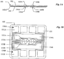
- FIG. 1A shows a cross-sectional view of an electrode module, fabricated using standard smart-card chip-module technology known in the art.
- the electrode module is described in detail in U.S. Pat. Publ. No. US 2002/017944 A1 .
- the module 101 of Fig. 1A comprises an epoxy foil element 102 laminated to a gold coated copper metal foil 103 with optional adhesive 102A.
- the epoxy foil element 102 has through-going holes at 104A and 104B.
- the metal foil 103 is formed into an array of electrode elements 130.
- the construction of the electrode elements will be discussed in the following by way of a pair of electrode elements 130A and 130B.
- Each electrode element 130A and 130B has a connection end 131A, 131B for connection to a measuring circuit in a card reader (not shown) and a sensor end 132A and 132B under the through-going holes in the epoxy 104A and 104B.
- the electrode module is received from the vendor on a 35 mm web.
- membranes 105A and 105B are applied to the module on the web extending laterally beyond the perimeter of the holes 104A, 104B and overlaying the top epoxy surface, and extending through the holes to contact the metal electrodes at the sensor ends 132A and 132B.
- the module is excised from the web using a die cutter, then placed and sealed into a housing in the diagnostic card as described later.
- the excised module of the Fig. 1 design is about 11 mm square by 120 micrometers thickness.
- Fig. 1B shows a bottom view (metal foil side) of a module with eight electrode elements, comprising the laminated epoxy foil 102 and metal foil 103.
- This figure shows in more detail the spatial arrangement of the metal electrode elements.
- two electrodes 130A, 130B, representative of the eight, are labeled to show the relationship between their sensor ends 132A and 132B and their connection ends 131A and 131B.
- the metal conductor paths 133 are generally long and thin to minimize lateral heat transport along them when the module is being heated.
- Heater contacts 134A, 134B of the metal foil 103 are electrically isolated from the eight electrode elements. These regions are for physical contacting by a heater block of the card reader, as described in more detail later.
- Fig. 1C shows the module of Figure 1B in top view (epoxy foil side).
- the position of the electrodes on the underside of the module is shown in the narrow dashed line.
- the electrodes are not labeled for reasons of clarity.
- the layout of the module comprises three distinct regions.
- the central region of the module is the sensor region 12.
- This region of the module is proximal to a fluidic conduit in the card when the module is assembled into the diagnostic card, as described later.
- the region proximal to the location of the lower heater block of the card reader when the card is in the card reader's card insertion orifice is the heater contact region 13.
- the region on the periphery of the module where electrical contact is made by the card reader to the metal electrodes on the underside of the module is the contact region 14.
- the same standard module fabrication technology can be used to make modules with many different electrode numbers and geometries. They differ only in the tooling to provide different locations of the through-going holes 104 (see Figures 1A and 1B ), and the mask art-work used to photolithographically define different spatial arrangements of the formed metal elements 103.
- the general arrangement of any module will include a sensor region 12 approximately centrally located, a heater contact region 13 at least partially adjacent the sensor region, and an electrical contact region 14 toward the module's periphery.
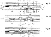
- Fig. 2A shows a top plan view and Figs. 2B-E show cross-sectional schematic views of a preferred embodiment of a diagnostic card including a sensor array on an electrode module, including the card's relationship to elements of the card reader's card insertion orifice when the card is in the card insertion orifice during the use of the card.
- Fig. 2B shows one cross-sectional schematic taken along the fluidic path AA' of Fig. 2A , the fluidic path extending from a calibrator fluid chamber 220 along a fluidic channel 210, through the measurement cell 211 to a waste channel 241.
- Figs. 2C-E show schematics along the fluidic path BA' of Fig. 2A , being along a fluidic path from the sample entry port 251 through the measurement cell 211 to the waste channel 241.
- the diagnostic card in the preferred embodiment is formed from a credit-card sized (85mm x 53mm x 1mm thick) molded plastic card body 200 with an electrode module 101 as generally described above with reference to Figures 1A-1C embedded in the lower surface of the card body.
- the electrode module comprises an epoxy foil element 102 with die-cut through-going passages, the epoxy element being laminated with a metal foil that has been formed into eight electrode elements.
- Two electrode elements 130A, 130B are shown in Figure 2B which have a sensor end 132A and 132B respectively and a contact end 131A, 131B respectively as are shown in the side-view schematic diagram.
- Membranes 207 and 208 are shown on the top surface of the module and contacting underside metal elements at the sensor ends 132A and 132B through the passages in the epoxy.
- the card body 200 also contains molded features (grooves, trenches and holes) on both its upper (solid lines in the top view schematic) and lower (dotted lines in the top view schematic) surfaces which molded features, when sealed by other laminating elements, form fluidic channels and a sealed fluid reservoir.
- Laminations are made to the lower and upper surface of the housing by label elements 201 and 202 and by metal foil elements 223A and 223B.
- Elements 201, 202 on the lower and upper surfaces of the card are label elements die-cut from an adhesive coated polymer sheet.
- Elements 223A and 223B are a lamination of two elements which are die-cut from a sheet of metal foil coated with polyethylene for heat sealing.
- the diagnostic card also includes a sample inlet port 251 which is in fluid communication with a second channel 250 connecting the sample inlet port 251 to the measurement cell 211.
- a chamber outlet valve 230 for fluidically connecting the calibrator fluid chamber 220 with the connecting channel 210 between the measurement cell 211 and the calibrator fluid chamber without pressurizing fluid contained within the chamber. This means the valve structure is operated/operable independent of any pressurization of fluid in the chamber.
- the valve is preferably a rupturing structure for rupturing the wall of the sealed chamber at the connection with the connecting conduit for fluidically connecting the chamber to the conduit.
- the chamber rupturing structure includes a bore 233 through the body 200 and a rupture element, in this case plug 234, located in the bore and within the chamber 220 between the two metal foil elements 223A and 223B.
- the plug is slightly smaller in diameter than the bore, rendering it capable of axial movement therein, in this case upwards.
- the plug 234 is positioned so that a region of the metal foil element 223A on the peripheral edge of the plug (295 of Fig. 2D ) ruptures when the plug is pushed upwards.
- the diagnostic card further includes a delivery structure for forcing fluid from the chamber 220 under pressure, when the chamber contains fluid, and into the connecting conduit 210.
- the delivery structure is a portion of the chamber walls which is sufficiently flexible to be deformed, preferably from the exterior of the card and while the card is inserted in the card reader.
- the delivery structure can also be any other structure usable for reliably forcing fluid from the chamber when the chamber is fluidically connected to the connecting conduit.
- Figs. 2C-E schematically show the card in the card orifice of a card reader (the card reader preferably including a circuit board with detectors, amplifiers and other circuit components, as described in co-pending U.S. Pat. Publn. No. 2003/0148530A1 ) and illustrate the spatial relationship between elements of the card and elements of the card-reader's orifice during use of the device.
- the card is first inserted into a card reader's card insertion orifice ( Fig. 2C ).
- the orifice comprises a lower generally planar mating element 280 which is co-planar with and proximal to the card's lower surface, and an upper generally planar mating element 290 which is co-planar with and proximal to the card's upper surface.
- the card reader's card insertion orifice has a guide (not shown) to locate the features on the card with their respective mating features on the card reader insertion orifice's planar mating elements during card insertion. After insertion, the two mating elements of the card reader insertion orifice are moved toward each other, thus clamping the card between them.
- the construction and function of the card reader is described in detail in co-pending U.S. Pat. Publn. No. 2003/148530A1 .
- a pin element 282 provided on the mating element 280 first contacts the card at the calibrator fluid chamber outlet valve 230.
- the pin 282 pushes plug 234 upwards. This lifts the metal foil laminate above the plug causing foil 223A to break at location 295 ( Fig. 2D ), thus fluidically opening the calibrator fluid chamber.
- the electrode module is electrically contacted by a contacting means of the card reader which comprises a contacting array of eight metal contact elements formed in a metal film or foil 286 on an insulating flex connector substrate 287. Two of the eight pins are shown in the side view schematics of Fig. 2C-E .
- Each has a contact end 283A, 283B for making z-action contact to the module's electrode contact locations 131A, 131B on the lower surface of the electrode module, and an end 284A, 284B for connection to an electrical circuit elsewhere in the card reader.
- the flex connector at its module contacting end is mounted on the movable end of a set of flexible cantilevers 285A and 285B, preferably made of plastic, whose other end is embedded in the lower mating element 280 of the card reader orifice.
- the cantilevers with the flex connector mounted on it, are in their at-rest position raised above the plane of the lower mating element 280 at the location of contact to the module, so that as the card is clamped to the lower mating element of the card reader orifice the cantilevers are depressed, thus providing z-action contact force to the electrical contacts made between the flex connector of the card reader and the electrode module of the card.
- the card's electrode module is thermally contacted by a lower heater block 289 and the top of the diagnostic card above the measurement chamber by an upper heater block 291.
- the lower heater block 289 which is mounted in the card reader orifice's lower mating element 280, makes thermal contact with the module on its lower surface directly under the measurement chamber 211, making physical contact to the module's 'split ring' heater contact metal elements 134A, 134B, while being in close proximity to the other metal elements elsewhere on the module, but electrically isolated from them.
- the upper heater block 291 which is mounted in the card reader orifice's upper mating element, makes thermal contact to the card directly above the measurement chamber 211.
- Each heater block contains a heater element and a temperature measuring element each in intimate thermal contact with the block (not shown). The blocks' heater elements and temperature measuring elements are also connected to the card reader's electrical circuit.
- the lower mating element 280 of the card reader also includes an actuator element 281 positioned to be opposite the calibrator fluid chamber 220 when the card is inserted into the card reader's card orifice.
- the actuator element 281 now engages the delivery structure of the calibrator fluid chamber 220, deforming the chamber wall 223 and compressing the chamber 220, thereby pressurizing the chamber contents and causing delivery of fluid out of the chamber along fluidic channel 210 to measurement chamber 211 ( Fig. 2E ).
- the card-reader prompts the user to supply sample fluid to the diagnostic card.
- the user engages a syringe containing sample fluid to the card's sample entry port (251 of Fig. 2A and 2B ).
- the syringe tip forms a seal with an adhesive element 253 surrounding the entry port.
- the sample port 251 may optionally be reversibly sealed with a closure flap which can be part of the label 202.
- the user delivers sample fluid from the syringe to the measurement cell 211 along channel 250, thus displacing calibrator fluid out of chamber 211 to waste channel 241.
- the module's sensors now generate sensor signals derived from the sample fluid, which electrical signals are extracted from the electrode module via the card reader's electrical flex connector 287 to an electrical circuit in the reader. After completion of the measurement cycle, the card is unclamped and withdrawn from the card reader's orifice.
- Step 1 sealing the electrode module 100 to plastic card body 200.
- Step 2 forming the metal foil cladding around chamber 220 by laminating first lamination 223A and second 223B lamination of metal foil elements with insertion of the rupture plug 234 between these laminations; filling of the clad calibrator chamber 220 with calibrator fluid 224; then sealing calibrator fluid and plug into the clad chamber.
- Step 3 laminate top 202 and bottom 201 labels. Steps 1 and 2 will now be described in more detail.
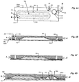
- Fig 3A and B show in more detail the electrode module assembled into the plastic card body 200 in step 1 of the assembly process.
- the molded plastic card body 200 as received from the vendor, is first laminated with the electrode module 100 whose epoxy foil upper surface 102 faces the card body and is recessed into it and sealed with adhesive 303.
- the adhesive is applied to the outer area of the module's epoxy surface perimetric to the module's central sensor region.
- the adhesive is applied to the entire top epoxy surface, except the sensor region (region 12 shown in Fig. 1C ).
- the module when embedded in the card, is coplanar with the card body with the module's upper sensor surface proximal to the card body's fluid measurement cell 211 and the module's lower metal surface 103 facing the outside.
- Fig. 3A and 3B also show in more detail the location of the card reader's heater blocks relative to the card and its electrode module when the card is clamped in the card reader's card insertion orifice.
- Fig. 3A shows a cross-section along AA' of the electrode module shown in Fig. 1C , which is in the direction orthogonal to the card's fluidic channel over the electrode module.
- Fig. 3B shows a cross-section along BB' of the electrode module shown in Fig. 1C , which is in the direction along the path of the card's fluidic channel over the electrode module.
- the lower heater block 289 physically contacts the electrode module at the locations 134A and 134B which are the electrode module's heater contact metal elements.
- the lower heater block 289 is in close proximity to (thus thermally connected with) but electrically isolated from, other metal elements of the electrode module 100, including the sensor ends 132 and contact ends 131 of the electrodes and the metal paths 133 between them.
- the lower heater block 289 extends a distance beyond the width of the fluidic measurement chamber 211.
- the lower heater block is in close proximity to the metal paths 133 connecting the electrodes' sensor ends 132 to their contact ends 131 but not in physical contact with them.
- the upper heater block 291 makes contact to the card's upper plastic label. It too extends beyond the width of the measurement chamber 211 ( Fig. 3A ), but also extends a distance along the fluidic channel beyond the electrode module on both sides ( Fig. 3B ). We have found that when the upper heater extends about 5mm beyond the module there is satisfactory thermal bootstrapping of the fluid beyond the sensor region of the module, thus assuring excellent thermal control of the temperature of the sensor region.
- the regions of the heater block not in contact with, but in proximity to the module should be spaced about 25 micrometers from the module's metal surface. At this distance there is still satisfactory heat transfer from heater block to module, but there is also reliable electrical isolation during repeated use of the card reader. In general, the rate of heat transfer from the heater block to the module increases with decreasing spacing. The preferred range of spacing is 10 to 50 micrometers. However, the person skilled in the art will appreciate that a spacing below 10 micrometers may be usable as long as reliable electrical insulation of the heater block from the sensing and contacting regions of the module is ensured. A spacing above 50 micrometers is usable, but the heat transfer rate will be low.
- Fig 4 shows in more detail the metal foil clad calibrator fluid chamber 220 and the foil rupturing plug, and its forming, filling and sealing processes which together are step 2 of the card assembly procedure.
- Fig. 4A which is a top view schematic of the card's calibrator fluid reservoir region
- Fig. 4B which is a cross-section through the embodiment of Figure 4A taken along line AA', being along the fluidic path from the calibrator fluid fill hole 221 along the calibrator fluid reservoir 220, its connecting channel 405 to the vent hole 222.
- the card body 200 in the calibrator fluid reservoir region of the card features a molded calibrator fluid reservoir cavity 401 (shown here as two parallel cavities fluidically connected), a molded trench 405 connecting the cavity 401 to a rupture-plug bore 233 and a second trench 210 connecting the rupture-plug bore to the measurement cell 211 (see Figure 2A ).
- a first metal foil element 223A has a pressure sensitive adhesive on one side of the metal and approximately 25 micrometers thickness polyethylene coating on the other.
- the element 223A which is die cut from a sheet and placed with its adhesive side down onto the card body, extends over the calibrator fluid reservoir cavity 401, the connecting channel 405 and the rupture-plug bore 233, overlaying all these features and extending to a perimeter beyond them.
- foil element 223A When high air pressure is applied to the foil element 223A it deforms taking the contour of the card body's reservoir cavity 401, connecting channel 405 and rupture-plug hole 233, being then attached to the body's surface by the pressure sensitive adhesive.
- the polyethylene coated surface of foil element 223A faces the inside of the reservoir cavity.
- the foil deforming procedure is similar to the blow-molding process well known in the art. In manufacture, a tool with an air pressurizable cavity is engaged to the foil on the card body and sealed to it about the cavity, preferably by an elastomeric gasket. When high pressure air is introduced into the tool's cavity, the air blow-deforms the metal foil to take the contour of the card body.
- a rupture-plug element 234 which is a rigid disc approximately the same thickness as the card body with a diameter somewhat smaller than the diameter of the rupture-plug bore 233, is placed onto the foil element 223A in the depression in the foil formed over the rupture-plug bore 233.
- the foil element 223A is pierced at the bottom of fluid fill hole 221 and vent hole 222.
- a second polyethylene coated metal foil element 223B is laminated over the first foil element 223A with its polyethylene coating facing the polyethylene coating of element 223A.
- a heat seal is made between foil elements 223A and 223 B, by fusing the two polyethylene coating layers, everywhere except in the fill and vent regions 415 and 416 adjacent the fluid fill and vent holes 221 and 222 respectively.
- the foil clad calibrator fluid reservoir is sealed except for the fill and vent holes 221, 222 as shown in Fig. 4B and is now ready to receive fluid.
- Calibrator fluid 224 is introduced through fill hole 221 into chamber 220 filling it and partially filling the channel 405 while expelling air from the chamber through vent hole 222.
- the fill and vent regions 415 and 416 near the fill and vent holes 221, 222 are then sealed in a secondary heat seal process, thus entirely sealing the calibrator fluid and rupture plug within the two foil elements as shown in Figs. 4C and 4D .
- Lamination of the card body 200 with an upper pressure sensitive adhesive coated label element 202 now forms a channel 210 which fluidically connects the region 450 of the calibrator chamber where the rupture of the foil takes place ( Fig. 4D ) with the measurement cell 211 (see Figure 2A ).
- a second lower label lamination 201 which leaves the lower surface of the electrode module 100 exposed completes the card assembly.
- the mean time to failure of a sealed fluid used for sensor calibration is the time for the carbon dioxide partial pressure to drop from its initial value in the fluid to an unacceptably low level as the gas permeates out through the heat fused polyethylene seam.
- the perimeter seal width to be greater than 3mm width at all locations along the perimeter. This high level of stability is in marked contrast to other devices of the known art, which must be stored in the refrigerator to achieve extended lifetime.
- the various elements of the diagnostic card can be used together as they are in the card of this disclosure, or they can be used separately in different card designs.
- the sealed fluid chamber and its valve structure means can be incorporated into diagnostic cards comprising micro-porous fluidic elements such as those as disclosed in U.S. Pat. Appln. 10/649,683 .
- the sealed fluid is used for priming the micro-porous pump elements rather than for sensor calibration purposes.
- the fluidic arrangements and sealed fluid chamber can be advantageously used with electrode modules comprising foil laminates as described in this disclosure, but they can also be used with sensor modules of other kinds, including the many types of sensor modules of the known art which are fabricated on a planar insulating substrates (microfabricated chips, planar circuit boards and the like) and including sensor modules incorporating non-electrochemical sensing means such as optical, chemiluminescence or fluorescence, as are known in the art. Indeed, these fluidic components will be useful in any unit-use diagnostic card incorporating an on-board fluid.
Landscapes
- Chemical & Material Sciences (AREA)
- Health & Medical Sciences (AREA)
- Chemical Kinetics & Catalysis (AREA)
- Analytical Chemistry (AREA)
- General Health & Medical Sciences (AREA)
- Hematology (AREA)
- Life Sciences & Earth Sciences (AREA)
- Clinical Laboratory Science (AREA)
- Dispersion Chemistry (AREA)
- Physics & Mathematics (AREA)
- Biochemistry (AREA)
- General Physics & Mathematics (AREA)
- Immunology (AREA)
- Pathology (AREA)
- Electrochemistry (AREA)
- Molecular Biology (AREA)
- Biophysics (AREA)
- Fluid Mechanics (AREA)
- Automatic Analysis And Handling Materials Therefor (AREA)
- Investigating Or Analysing Materials By The Use Of Chemical Reactions (AREA)
- Investigating Or Analyzing Materials By The Use Of Electric Means (AREA)
Claims (11)
- Carte de diagnostic destinée à être utilisée avec un lecteur de carte pour détecter au moins une concentration de composant d'un échantillon de fluide, comprenant :un corps de carte (200),au moins un capteur de composant situé dans une région de capteur du corps de carte (200), une chambre étanchéifiée (220) définie dans le corps de carte (200) en dehors de la région de capteur pour contenir un fluide ;un conduit de fluide (210) pour relier fluidiquement la chambre à la région de capteur;une soupape (230) située dans la chambre pour relier fluidiquement la chambre (220) au conduit de fluide (210) ; etune structure de livraison séparée et distincte de la soupape pour forcer le fluide de la chambre (220), lorsque la chambre contient du fluide et lorsque la chambre est reliée fluidiquement au conduit de fluide (210) par la soupape (230), dans le conduit de fluide (210), où la chambre (220) est formée d'un stratifié de deux feuilles stratifiées de métal opposées revêtues de plastique (223A; 223B) collés autour de leur périmètre par un premier thermoscellage réalisé par collage en fusion des revêtements plastiques des stratifiées,caractérisée en ce que la chambre (220) définie dans le corps de carte (200) comprend des orifices séparés de remplissage et de ventilation (221 ; 222) pour remplir la chambre avec un fluide sans pressurisation, etla soupape à l'intérieur de la chambre étanchéifiée (220) est capable de relier fluidiquement la chambre au conduit de fluide (210) sans pressurisation du fluide contenu dans la chambre, où la structure de soupape peut fonctionner indépendamment de toute pressurisation du fluide dans la chambre (220).
- Carte de diagnostic selon la revendication 1, dans laquelle le thermoscellage a une largeur d'au moins 3 mm.
- Carte de diagnostic selon la revendication 1, dans laquelle la chambre (220) contient un fluide et les orifices de remplissage et de ventilation (221 ; 222) sont étanchéifiés de manière à étanchéifier complètement la chambre remplie.
- Carte de diagnostic selon la revendication 3, dans laquelle les orifices de remplissage et de ventilation (221 ; 222) sont étanchéifiés par un second thermoscellage réalisé par collage en fusion des revêtements plastiques des stratifiés autour des orifices de remplissage et de ventilation.
- Carte selon la revendication 1, dans laquelle la chambre (220) est étanchéifiée par une paroi de chambre, le corps de carte (200) comprend un siège de soupape et la soupape comprend un corps de soupape reçu de manière déplaçable dans le siège de soupape, le corps de soupape et le siège de soupape étant formés et construits pour rompre une partie de la paroi de chambre lors du déplacement du corps de soupape relativement au siège de soupape.
- Carte selon la revendication 1, dans laquelle la soupape comprend un corps de soupape reçu de manière déplaçable dans un siège de soupape dans le corps de carte, le corps de soupape étant pris en sandwich entre les stratifications avec la chambre, le corps de soupape et le siège de soupape étant formés et construits pour rompre une des stratifications lors du déplacement du corps de soupape par rapport au siège de soupape.
- Carte selon la revendication 6, dans laquelle le corps de soupape est un connecteur de rupture (234) et la soupape en soi est un alésage de réception de connecteur (233) dans le corps de carte.
- Carte selon la revendication 7, dans laquelle le connecteur (234) et l'alésage de réception du connecteur (233) comportent des bords coopérants pour rompre l'une des stratifications lors du déplacement du connecteur dans l'alésage de réception du connecteur.
- Carte selon la revendication 1, dans laquelle le corps de carte (200) comporte des contours moulés et l'une des feuilles stratifiées (223A; 223B) est formée par pression dans les contours du corps de carte.
- Carte selon la revendication 1, dans laquelle la chambre (220) présente une paroi de chambre et un volume de chambre et la structure de livraison est formée par une partie flexible de la paroi de chambre qui est déformable pour réduire le volume de la chambre.
- Carte selon la revendication 1, dans laquelle la chambre (220) est constituée d'une paire de feuilles stratifiées de métal opposées, revêtues de plastique (223A ; 223B) définissant la paroi de chambre et collées autour de leur périmètre par un premier thermoscellage réalisé par collage en fusion des revêtements plastiques des stratifiés sur leur périmètre, le corps de carte comprenant en outre un orifice de remplissage en communication avec la chambre à travers l'une des stratifications pour remplir la chambre avec un fluide ; et un orifice de ventilation à distance de l'orifice de remplissage et en communication avec la chambre à travers une des stratifications pour la ventilation de l'air dans la chambre pendant le remplissage de la chambre avec le fluide, les orifices de remplissage et de ventilation (221 ; 222) pouvant être étanchéifiés pour étanchéifier totalement la chambre par un second thermoscellage par collage en fusion des revêtements plastiques autour des orifices de remplissage et de ventilation.
Priority Applications (2)
| Application Number | Priority Date | Filing Date | Title |
|---|---|---|---|
| DK19186918.9T DK3581912T3 (da) | 2004-06-01 | 2005-06-01 | Diagnoseindretninger med indbygget fluidik |
| EP19186918.9A EP3581912B1 (fr) | 2004-06-01 | 2005-06-01 | Dispositifs de diagnostic intégrant des éléments fluidiques |
Applications Claiming Priority (2)
| Application Number | Priority Date | Filing Date | Title |
|---|---|---|---|
| US10/856,782 US7842234B2 (en) | 2002-12-02 | 2004-06-01 | Diagnostic devices incorporating fluidics and methods of manufacture |
| PCT/CA2005/000843 WO2005119200A1 (fr) | 2004-06-01 | 2005-06-01 | Dispositifs de diagnostic intégrant des éléments fluidiques et procédés de fabrication |
Related Child Applications (2)
| Application Number | Title | Priority Date | Filing Date |
|---|---|---|---|
| EP19186918.9A Division EP3581912B1 (fr) | 2004-06-01 | 2005-06-01 | Dispositifs de diagnostic intégrant des éléments fluidiques |
| EP19186918.9A Division-Into EP3581912B1 (fr) | 2004-06-01 | 2005-06-01 | Dispositifs de diagnostic intégrant des éléments fluidiques |
Publications (3)
| Publication Number | Publication Date |
|---|---|
| EP1756544A1 EP1756544A1 (fr) | 2007-02-28 |
| EP1756544A4 EP1756544A4 (fr) | 2012-09-19 |
| EP1756544B1 true EP1756544B1 (fr) | 2019-09-04 |
Family
ID=35463009
Family Applications (2)
| Application Number | Title | Priority Date | Filing Date |
|---|---|---|---|
| EP19186918.9A Active EP3581912B1 (fr) | 2004-06-01 | 2005-06-01 | Dispositifs de diagnostic intégrant des éléments fluidiques |
| EP05749838.8A Active EP1756544B1 (fr) | 2004-06-01 | 2005-06-01 | Dispositifs de diagnostic intégrant des éléments fluidiques et procédés de fabrication |
Family Applications Before (1)
| Application Number | Title | Priority Date | Filing Date |
|---|---|---|---|
| EP19186918.9A Active EP3581912B1 (fr) | 2004-06-01 | 2005-06-01 | Dispositifs de diagnostic intégrant des éléments fluidiques |
Country Status (6)
| Country | Link |
|---|---|
| US (4) | US7842234B2 (fr) |
| EP (2) | EP3581912B1 (fr) |
| JP (2) | JP4498415B2 (fr) |
| CA (4) | CA3053756C (fr) |
| DK (2) | DK1756544T3 (fr) |
| WO (1) | WO2005119200A1 (fr) |
Families Citing this family (62)
| Publication number | Priority date | Publication date | Assignee | Title |
|---|---|---|---|---|
| US7767068B2 (en) | 2002-12-02 | 2010-08-03 | Epocal Inc. | Heterogeneous membrane electrodes |
| US7842234B2 (en) | 2002-12-02 | 2010-11-30 | Epocal Inc. | Diagnostic devices incorporating fluidics and methods of manufacture |
| AT502915B1 (de) * | 2004-12-23 | 2008-01-15 | Hoffmann La Roche | Vorrichtung zur thermostatisierung einer messzelle in einem analysator und messzelle, welche in einen analysator austauschbar einsetzbar ist |
| US8075852B2 (en) * | 2005-11-02 | 2011-12-13 | Affymetrix, Inc. | System and method for bubble removal |
| US20090188811A1 (en) * | 2007-11-28 | 2009-07-30 | Edwards Lifesciences Corporation | Preparation and maintenance of sensors |
| US8216529B2 (en) * | 2008-09-15 | 2012-07-10 | Abbott Point Of Care Inc. | Fluid-containing pouches with reduced gas exchange and methods for making same |
| US8448499B2 (en) | 2008-12-23 | 2013-05-28 | C A Casyso Ag | Cartridge device for a measuring system for measuring viscoelastic characteristics of a sample liquid, a corresponding measuring system, and a corresponding method |
| DE102009043228A1 (de) * | 2009-02-04 | 2010-09-02 | Siemens Aktiengesellschaft | Anordnung und Verfahren zum elektrochemischen Messen von biochemischen Reaktionen sowie Herstellungsverfahren der Anordnung |
| WO2011062738A1 (fr) | 2009-11-23 | 2011-05-26 | Mikhail Briman | Activation électrochimique commandée d'électrodes à base de carbone |
| EP2468403A1 (fr) * | 2010-12-21 | 2012-06-27 | Koninklijke Philips Electronics N.V. | Procédé pour la fabrication d'un dispositif microfluidique |
| US8709353B2 (en) * | 2011-03-24 | 2014-04-29 | Boehringer Ingelheim Microparts Gmbh | Device and method for producing a fluidic connection between cavities |
| US9638663B2 (en) | 2011-07-25 | 2017-05-02 | Proxim Diagnostics Corporation | Cartridge for diagnostic testing |
| US9430957B2 (en) | 2011-09-28 | 2016-08-30 | Shenzhen China Star Optoelectronics Technology Co., Ltd. | Virtual load board and test system and test method for liquid crystal display control board |
| EP2606974A1 (fr) * | 2011-12-19 | 2013-06-26 | Nxp B.V. | Système de détection optique, cartouche associée et lecteur correspondant |
| ES2682281T3 (es) | 2012-03-16 | 2018-09-19 | Stat-Diagnostica & Innovation, S.L. | Cartucho de prueba con módulo de transferencia integrado |
| EP3539471A1 (fr) | 2012-04-04 | 2019-09-18 | University of Cincinnati | Systèmes de simulation, de collecte et de détection de sueur |
| ES2439624B1 (es) * | 2012-06-19 | 2014-10-28 | Laboratorios Alpha San Ignacio Pharma, S.L. | Tarjeta de diagnóstico desechable y dispositivo electrónico de lectura |
| US9289761B2 (en) | 2012-11-16 | 2016-03-22 | Honeywell International Inc. | Card waste storage mechanism |
| WO2014159615A2 (fr) * | 2013-03-14 | 2014-10-02 | Abbott Point Of Care Inc | Système de régulation thermique permettant de réguler la température d'un fluide |
| US10182795B2 (en) | 2013-10-18 | 2019-01-22 | University Of Cincinnati | Devices for integrated, repeated, prolonged, and/or reliable sweat stimulation and biosensing |
| JP2016533227A (ja) | 2013-10-18 | 2016-10-27 | ユニバーシティ・オブ・シンシナティ | 経時的保証を伴う汗感知 |
| US10888244B2 (en) | 2013-10-18 | 2021-01-12 | University Of Cincinnati | Sweat sensing with chronological assurance |
| US11033898B2 (en) | 2014-02-01 | 2021-06-15 | Ezmems Ltd. | Fluidic microelectromechanical sensors/devices and fabrication methods thereof |
| WO2015114635A1 (fr) * | 2014-02-01 | 2015-08-06 | Ezmems Ltd. | Dispositif de puce permettant de surveiller et de réguler un écoulement de fluide, et ses procédés de fabrication |
| JP6548356B2 (ja) * | 2014-03-20 | 2019-07-24 | キヤノンメディカルシステムズ株式会社 | 送液装置 |
| JP2017518814A (ja) | 2014-05-28 | 2017-07-13 | ユニバーシティ・オブ・シンシナティ | 発汗モニタリング及び薬物送達の制御 |
| EP3148416B8 (fr) | 2014-05-28 | 2024-04-17 | University of Cincinnati | Dispositifs à volumes de sueur réduits entre capteurs et glandes sudoripares |
| EP3148430A4 (fr) | 2014-05-28 | 2018-05-16 | University of Cincinnati | Stratégies perfectionnées fluidiques, d'étanchéité et d'adhérence de capteur de transpiration |
| US10814322B2 (en) | 2014-07-09 | 2020-10-27 | Siemens Healthcare Diagnostics Inc. | Low sample volume sensing device |
| WO2016011308A1 (fr) | 2014-07-17 | 2016-01-21 | Siemens Healthcare Diagnostics Inc. | Réseau de capteurs |
| WO2016049019A1 (fr) * | 2014-09-22 | 2016-03-31 | University Of Cincinnati | Détection de transpiration avec assurance analytique |
| EP3256049A4 (fr) | 2015-02-13 | 2018-07-25 | University of Cincinnati | Dispositifs de stimulation et de détection de sueur intégrées et indirectes |
| US10634602B2 (en) | 2015-06-12 | 2020-04-28 | Cytochip Inc. | Fluidic cartridge for cytometry and additional analysis |
| WO2016200922A1 (fr) | 2015-06-12 | 2016-12-15 | Cytochip Inc. | Unités fluidiques et cartouches pour une analyse de multiples analytes |
| US10077999B2 (en) | 2015-07-14 | 2018-09-18 | Cytochip Inc. | Volume sensing in fluidic cartridge |
| US10646142B2 (en) | 2015-06-29 | 2020-05-12 | Eccrine Systems, Inc. | Smart sweat stimulation and sensing devices |
| US20180317833A1 (en) | 2015-10-23 | 2018-11-08 | Eccrine Systems, Inc. | Devices capable of fluid sample concentration for extended sensing of analytes |
| US10674946B2 (en) | 2015-12-18 | 2020-06-09 | Eccrine Systems, Inc. | Sweat sensing devices with sensor abrasion protection |
| WO2017120464A1 (fr) * | 2016-01-08 | 2017-07-13 | Siemens Healthcare Diagnostics Inc. | Élément chauffant pour réseau de capteurs |
| JP6625004B2 (ja) | 2016-04-14 | 2019-12-25 | キヤノン株式会社 | カード型記録装置およびスロット装置 |
| US10094802B2 (en) * | 2016-06-01 | 2018-10-09 | EXIAS Medical GmbH | Heating system for a measurement cell |
| US10471249B2 (en) | 2016-06-08 | 2019-11-12 | University Of Cincinnati | Enhanced analyte access through epithelial tissue |
| WO2018006087A1 (fr) | 2016-07-01 | 2018-01-04 | University Of Cincinnati | Dispositif avec utilisant une faible quantité de sueur entre le capteur et les glandes sudoripares. |
| WO2018017619A1 (fr) | 2016-07-19 | 2018-01-25 | Eccrine Systems, Inc. | Conductivité de la sueur, taux de sudation volumétrique et dispositifs de réponse galvanique de la peau et applications |
| EP3485249A4 (fr) * | 2016-08-03 | 2020-01-22 | Ezmems Ltd. | Capteurs/dispositifs microfluidiques fluidiques et procédés de fabrication associés |
| US10736565B2 (en) | 2016-10-14 | 2020-08-11 | Eccrine Systems, Inc. | Sweat electrolyte loss monitoring devices |
| US11235327B2 (en) * | 2017-04-07 | 2022-02-01 | Easydx, Inc. | Point of care test cartridge |
| TWI758537B (zh) * | 2017-09-01 | 2022-03-21 | 大陸商深圳華大智造科技有限公司 | 與矽基感測器集成之射出成型微流體/流體卡匣 |
| US10710068B2 (en) * | 2017-09-20 | 2020-07-14 | e-SENSE, Inc. | Microfluidic chip with chemical sensor having back-side contacts |
| WO2019083844A1 (fr) | 2017-10-23 | 2019-05-02 | Cytochip Inc. | Dispositifs et méthode de mesure d'analytes et de particules cibles |
| CN108443579B (zh) | 2018-04-11 | 2020-06-26 | 利多(香港)有限公司 | 一种能控制液体流动的微阀及微流控芯片 |
| DE102018206066A1 (de) | 2018-04-20 | 2019-10-24 | Robert Bosch Gmbh | Vorrichtung zum Ankoppeln einer Kartusche für ein Chiplabor-Analysegerät, Chiplabor-Analysegerät und Verfahren zum Ankoppeln einer Kartusche für ein Chiplabor-Analysegerät |
| CN108709767B (zh) * | 2018-07-26 | 2023-12-01 | 中国电建集团成都勘测设计研究院有限公司 | 取土器 |
| EP3849703B1 (fr) | 2018-09-11 | 2022-08-10 | F. Hoffmann-La Roche AG | Cartouche comportant un emballage pour liquide |
| EP3647781B1 (fr) * | 2018-10-29 | 2024-05-01 | EXIAS Medical GmbH | Cartouche de mesure d'un échantillon liquide |
| JP7150324B2 (ja) * | 2018-11-16 | 2022-10-11 | 株式会社テクノメデイカ | 使い捨て検査具及び該検査具を用いる分析装置 |
| CA3134919C (fr) * | 2019-03-26 | 2022-11-15 | Siemens Healthcare Diagnostics Inc. | Procedes et et appareil pour effectuer des mesures d'echantillons en utilisant la lumiere visible sur des echantillons manipules avec des ondes acoustiques |
| CN112023990B (zh) | 2019-06-03 | 2023-06-23 | 利多(香港)有限公司 | 一种微流控检测芯片及制造方法 |
| CN112675933A (zh) | 2019-10-18 | 2021-04-20 | 利多(香港)有限公司 | 一种用于检测分析物的微流控芯片 |
| US11453001B2 (en) | 2020-01-29 | 2022-09-27 | International Business Machines Corporation | Microfluidic chips with integrated electronic sensors |
| US11859734B2 (en) * | 2020-11-16 | 2024-01-02 | Siemens Healthcare Diagnostics Inc. | Valve for microfluidic device |
| EP4016068A1 (fr) * | 2020-12-21 | 2022-06-22 | F. Hoffmann-La Roche AG | Ensemble capteurs |
Citations (1)
| Publication number | Priority date | Publication date | Assignee | Title |
|---|---|---|---|---|
| US5096669A (en) * | 1988-09-15 | 1992-03-17 | I-Stat Corporation | Disposable sensing device for real time fluid analysis |
Family Cites Families (102)
| Publication number | Priority date | Publication date | Assignee | Title |
|---|---|---|---|---|
| US4062750A (en) * | 1974-12-18 | 1977-12-13 | James Francis Butler | Thin film electrochemical electrode and cell |
| JPS51113788A (en) | 1975-03-12 | 1976-10-07 | Licentia Gmbh | Electrodes for electrochemical measuring elements for quantitative measurements of concentration of gases soluble in liquid electrolyte |
| FR2352300A1 (fr) | 1976-05-19 | 1977-12-16 | Eastman Kodak Co | Electrode pour le titrage selectif d'un ion |
| US4133735A (en) * | 1977-09-27 | 1979-01-09 | The Board Of Regents Of The University Of Washington | Ion-sensitive electrode and processes for making the same |
| US4276141A (en) * | 1978-02-24 | 1981-06-30 | Beckman Instruments, Inc. | Solid state ion selective electrodes |
| US4225410A (en) * | 1978-12-04 | 1980-09-30 | Technicon Instruments Corporation | Integrated array of electrochemical sensors |
| US4342964A (en) * | 1978-12-04 | 1982-08-03 | Transidyne General Corp. | Apparatus for electrochemical measurements |
| US4301412A (en) * | 1979-10-29 | 1981-11-17 | United States Surgical Corporation | Liquid conductivity measuring system and sample cards therefor |
| US4436610A (en) * | 1980-12-15 | 1984-03-13 | Transidyne General Corporation | Apparatus for measuring electrochemical activity |
| RO81891A2 (fr) | 1981-03-16 | 1983-06-01 | Institutul De Chimie,Ro | Electrode de reference |
| AT369254B (de) * | 1981-05-07 | 1982-12-27 | Otto Dipl Ing Dr Tech Prohaska | Medizinische sonde |
| US4534356A (en) * | 1982-07-30 | 1985-08-13 | Diamond Shamrock Chemicals Company | Solid state transcutaneous blood gas sensors |
| US4431508A (en) * | 1982-12-10 | 1984-02-14 | Brown Jr Harold M | Solid state graphite electrode |
| US5509410A (en) * | 1983-06-06 | 1996-04-23 | Medisense, Inc. | Strip electrode including screen printing of a single layer |
| US4604303A (en) * | 1983-05-11 | 1986-08-05 | Nissan Chemical Industries, Ltd. | Polymer composition containing an organic metal complex and method for producing a metallized polymer from the polymer composition |
| US4484987A (en) * | 1983-05-19 | 1984-11-27 | The Regents Of The University Of California | Method and membrane applicable to implantable sensor |
| JPS60108745A (ja) * | 1983-11-18 | 1985-06-14 | Ngk Insulators Ltd | 電気化学的装置 |
| US4739380A (en) * | 1984-01-19 | 1988-04-19 | Integrated Ionics, Inc. | Integrated ambient sensing devices and methods of manufacture |
| US4613422A (en) * | 1984-01-19 | 1986-09-23 | Integrated Ionics Inc. | Ambient sensing devices |
| US4551209A (en) * | 1984-01-19 | 1985-11-05 | Integrated Ionics, Inc. | Method of calibrating conductive metal oxide electrodes |
| US4654127A (en) * | 1984-04-11 | 1987-03-31 | Sentech Medical Corporation | Self-calibrating single-use sensing device for clinical chemistry and method of use |
| US5141868A (en) * | 1984-06-13 | 1992-08-25 | Internationale Octrooi Maatschappij "Octropa" Bv | Device for use in chemical test procedures |
| US4629424A (en) * | 1984-08-30 | 1986-12-16 | Integrated Ionics, Inc. | Intraoral ambient sensing device |
| US5030310A (en) * | 1985-06-28 | 1991-07-09 | Miles Inc. | Electrode for electrochemical sensors |
| US4734184A (en) * | 1985-08-29 | 1988-03-29 | Diamond Sensor Systems, Inc. | Self-activating hydratable solid-state electrode apparatus |
| US4592824A (en) * | 1985-09-13 | 1986-06-03 | Centre Suisse D'electronique Et De Microtechnique S.A. | Miniature liquid junction reference electrode and an integrated solid state electrochemical sensor including the same |
| US4689309A (en) * | 1985-09-30 | 1987-08-25 | Miles Laboratories, Inc. | Test device, method of manufacturing same and method of determining a component in a sample |
| US4864229A (en) * | 1986-05-03 | 1989-09-05 | Integrated Ionics, Inc. | Method and apparatus for testing chemical and ionic sensors |
| JPH0424442Y2 (fr) * | 1986-12-11 | 1992-06-09 | ||
| GB8720470D0 (en) * | 1987-08-29 | 1987-10-07 | Emi Plc Thorn | Sensor arrangements |
| AU3038789A (en) | 1988-01-21 | 1989-08-11 | Electro-Nucleonics Inc. | Dry ion-selective electrodes for the determination of ionic species in aqueous media |
| KR0157220B1 (ko) * | 1988-02-08 | 1999-03-30 | 리이드 알. 프리오어 | 금속 산화물 전극 |
| US4933048A (en) * | 1988-02-16 | 1990-06-12 | I-Stat Corporation | Reference electrode, method of making and method of using same |
| US4954087A (en) * | 1988-04-27 | 1990-09-04 | I-Stat Corporation | Static-free interrogating connector for electric components |
| CA1299653C (fr) | 1988-07-07 | 1992-04-28 | Markwell Medical Institute, Inc. | Appareil de mesure des liquides biologiques |
| FR2634894B1 (fr) * | 1988-07-28 | 1990-09-14 | Guigan Jean | |
| US4877528A (en) * | 1988-10-27 | 1989-10-31 | Bend Research, Inc. | Siloxane-grafted membranes |
| US5212050A (en) * | 1988-11-14 | 1993-05-18 | Mier Randall M | Method of forming a permselective layer |
| US5200051A (en) * | 1988-11-14 | 1993-04-06 | I-Stat Corporation | Wholly microfabricated biosensors and process for the manufacture and use thereof |
| US6306594B1 (en) * | 1988-11-14 | 2001-10-23 | I-Stat Corporation | Methods for microdispensing patterened layers |
| US5063081A (en) * | 1988-11-14 | 1991-11-05 | I-Stat Corporation | Method of manufacturing a plurality of uniform microfabricated sensing devices having an immobilized ligand receptor |
| US5008616A (en) * | 1989-11-09 | 1991-04-16 | I-Stat Corporation | Fluidics head for testing chemical and ionic sensors |
| US5078854A (en) * | 1990-01-22 | 1992-01-07 | Mallinckrodt Sensor Systems, Inc. | Polarographic chemical sensor with external reference electrode |
| JPH03221858A (ja) | 1990-01-26 | 1991-09-30 | Terumo Corp | 基準電極 |
| US5183549A (en) * | 1990-01-26 | 1993-02-02 | Commtech International Management Corporation | Multi-analyte sensing electrolytic cell |
| USD337164S (en) * | 1990-07-19 | 1993-07-06 | I-Stat Corporation | Cartridge for a blood monitoring analyzer |
| USD332833S (en) * | 1990-07-19 | 1993-01-26 | I-Stat | Portable clinical diagnostic instrument |
| US5112455A (en) * | 1990-07-20 | 1992-05-12 | I Stat Corporation | Method for analytically utilizing microfabricated sensors during wet-up |
| US5124661A (en) * | 1990-07-23 | 1992-06-23 | I-Stat Corporation | Reusable test unit for simulating electrochemical sensor signals for quality assurance of portable blood analyzer instruments |
| US5246576A (en) * | 1990-12-10 | 1993-09-21 | Ppg Industries, Inc. | Cathode in a layered circuit and electrochemical cell for a measurement of oxygen in fluids |
| AT398132B (de) * | 1991-02-15 | 1994-09-26 | Avl Verbrennungskraft Messtech | Vorrichtung zur messung der konzentration eines reagens |
| JPH0618476A (ja) | 1991-03-14 | 1994-01-25 | Rikagaku Kenkyusho | 水中の二酸化炭素濃度の測定方法 |
| US5286365A (en) | 1992-01-15 | 1994-02-15 | Beckman Instruments, Inc. | Graphite-based solid state polymeric membrane ion-selective electrodes |
| US5726026A (en) * | 1992-05-01 | 1998-03-10 | Trustees Of The University Of Pennsylvania | Mesoscale sample preparation device and systems for determination and processing of analytes |
| US5232667A (en) * | 1992-05-21 | 1993-08-03 | Diametrics Medical, Inc. | Temperature control for portable diagnostic system using a non-contact temperature probe |
| US5325853A (en) * | 1992-09-02 | 1994-07-05 | Diametrics Medical, Inc. | Calibration medium containment system |
| DE59310282D1 (de) * | 1992-09-14 | 2002-06-06 | Siemens Ag | Referenzelektrode |
| US5415746A (en) | 1992-12-21 | 1995-05-16 | E. I. Du Pont De Nemours And Company | Potentiometric ion determinations using enhanced selectivity asymmetric ion-selective membrane |
| JPH0816669B2 (ja) * | 1993-02-18 | 1996-02-21 | 日本電気株式会社 | グルコースセンサの製造方法 |
| GB9309797D0 (en) * | 1993-05-12 | 1993-06-23 | Medisense Inc | Electrochemical sensors |
| US5821399A (en) * | 1993-07-16 | 1998-10-13 | I-Stat Corporation | Automatic test parameters compensation of a real time fluid analysis sensing device |
| US5416026A (en) * | 1993-10-04 | 1995-05-16 | I-Stat Corporation | Method for detecting the change in an analyte due to hemolysis in a fluid sample |
| US5447440A (en) * | 1993-10-28 | 1995-09-05 | I-Stat Corporation | Apparatus for assaying viscosity changes in fluid samples and method of conducting same |
| CA2175056A1 (fr) * | 1993-10-28 | 1995-05-04 | Imants R. Lauks | Procede de prelevement et d'introduction d'un echantillon de fluide |
| US5609824A (en) * | 1994-07-13 | 1997-03-11 | I-Stat Corporation | Methods and apparatus for rapid equilibration of dissolved gas composition |
| US5514253A (en) * | 1994-07-13 | 1996-05-07 | I-Stat Corporation | Method of measuring gas concentrations and microfabricated sensing device for practicing same |
| US5554272A (en) * | 1995-08-10 | 1996-09-10 | Ciba Corning Diagnostics Corp. | Planar bicarbonate sensor |
| US5656241A (en) * | 1995-09-07 | 1997-08-12 | Optical Sensors Incorporated | Method for manufacturing fiber optic sensors |
| US6241862B1 (en) | 1996-02-14 | 2001-06-05 | Inverness Medical Technology, Inc. | Disposable test strips with integrated reagent/blood separation layer |
| US5708247A (en) * | 1996-02-14 | 1998-01-13 | Selfcare, Inc. | Disposable glucose test strips, and methods and compositions for making same |
| JPH09299445A (ja) | 1996-05-14 | 1997-11-25 | Sekisui Chem Co Ltd | 薬物含有貼付剤用包装体 |
| US6440725B1 (en) * | 1997-12-24 | 2002-08-27 | Cepheid | Integrated fluid manipulation cartridge |
| JP4041560B2 (ja) | 1997-09-09 | 2008-01-30 | 株式会社テクノメデイカ | 検査液分析装置用使い捨て成分検出具及び前記成分検査具に対する検査液供給方法 |
| US6030827A (en) * | 1998-01-23 | 2000-02-29 | I-Stat Corporation | Microfabricated aperture-based sensor |
| US6016066A (en) | 1998-03-19 | 2000-01-18 | Intel Corporation | Method and apparatus for glitch protection for input buffers in a source-synchronous environment |
| KR100349000B1 (ko) | 1998-07-09 | 2003-03-26 | 주식회사 아이센스 | 친수성폴리우레탄을사용한바이오센서의제조방법 |
| KR100342165B1 (ko) | 1999-03-25 | 2002-06-27 | 배병우 | 자기 진단기능을 갖는 소형 고체상 기준전극 |
| DE19916921A1 (de) | 1999-04-14 | 2000-10-19 | Fraunhofer Ges Forschung | Elektrisches Sensorarray |
| JP2000298111A (ja) | 1999-04-15 | 2000-10-24 | Sentan Kagaku Gijutsu Incubation Center:Kk | バイオセンサー |
| US6432296B1 (en) * | 1999-09-24 | 2002-08-13 | Daniel S. Daniel | Polymeric compositions for ion-selective electrodes |
| US6750053B1 (en) * | 1999-11-15 | 2004-06-15 | I-Stat Corporation | Apparatus and method for assaying coagulation in fluid samples |
| US6451191B1 (en) * | 1999-11-18 | 2002-09-17 | 3M Innovative Properties Company | Film based addressable programmable electronic matrix articles and methods of manufacturing and using the same |
| US20030057108A1 (en) * | 1999-12-10 | 2003-03-27 | Ramamurthi Sridharan | Device and method for accelerated hydration of dry chemical sensors |
| US6484045B1 (en) * | 2000-02-10 | 2002-11-19 | Medtronic Minimed, Inc. | Analyte sensor and method of making the same |
| US6438498B1 (en) * | 2000-02-10 | 2002-08-20 | I-Stat Corporation | System, method and computer implemented process for assaying coagulation in fluid samples |
| JP4621404B2 (ja) * | 2000-04-18 | 2011-01-26 | 株式会社テクノメデイカ | 養液栽培の試液分析装置 |
| KR100379792B1 (ko) * | 2000-06-12 | 2003-04-11 | 주식회사 아이센스 | 마이크로 칩형 이산화탄소 기체센서 |
| US6793789B2 (en) | 2000-09-30 | 2004-09-21 | Geun Sig Cha | Reference electrode with a polymeric reference electrode membrane |
| US6896778B2 (en) * | 2001-06-04 | 2005-05-24 | Epocal Inc. | Electrode module |
| US6845327B2 (en) * | 2001-06-08 | 2005-01-18 | Epocal Inc. | Point-of-care in-vitro blood analysis system |
| US6766817B2 (en) * | 2001-07-25 | 2004-07-27 | Tubarc Technologies, Llc | Fluid conduction utilizing a reversible unsaturated siphon with tubarc porosity action |
| US6780307B2 (en) | 2001-10-12 | 2004-08-24 | The United States Of America As Represented By The Secretary Of The Navy | Ion selective electrodes for direct organic drug analysis in saliva, sweat, and surface wipes |
| US7419821B2 (en) * | 2002-03-05 | 2008-09-02 | I-Stat Corporation | Apparatus and methods for analyte measurement and immunoassay |
| US7226978B2 (en) | 2002-05-22 | 2007-06-05 | Dexcom, Inc. | Techniques to improve polyurethane membranes for implantable glucose sensors |
| US20040018577A1 (en) * | 2002-07-29 | 2004-01-29 | Emerson Campbell John Lewis | Multiple hybrid immunoassay |
| US7094330B2 (en) * | 2002-12-02 | 2006-08-22 | Epocal Inc. | Heterogeneous membrane electrodes |
| US7842234B2 (en) * | 2002-12-02 | 2010-11-30 | Epocal Inc. | Diagnostic devices incorporating fluidics and methods of manufacture |
| US7723099B2 (en) * | 2003-09-10 | 2010-05-25 | Abbott Point Of Care Inc. | Immunoassay device with immuno-reference electrode |
| US7682833B2 (en) * | 2003-09-10 | 2010-03-23 | Abbott Point Of Care Inc. | Immunoassay device with improved sample closure |
| AU2004288004B2 (en) * | 2003-10-31 | 2009-06-11 | Lifescan Scotland Limited | Method of reducing the effect of direct interference current in an electrochemical test strip |
| ES2362790T3 (es) * | 2004-09-02 | 2011-07-13 | Abbott Point Of Care, Inc. | Sensor de nitrógeno ureico en sangre (bun). |
| US7918978B2 (en) * | 2005-07-14 | 2011-04-05 | I-Stat Corporation | Photoformed silicone sensor membrane |
-
2004
- 2004-06-01 US US10/856,782 patent/US7842234B2/en active Active
-
2005
- 2005-06-01 CA CA3053756A patent/CA3053756C/fr active Active
- 2005-06-01 WO PCT/CA2005/000843 patent/WO2005119200A1/fr active Application Filing
- 2005-06-01 CA CA2869920A patent/CA2869920C/fr active Active
- 2005-06-01 CA CA2594370A patent/CA2594370C/fr active Active
- 2005-06-01 DK DK05749838T patent/DK1756544T3/da active
- 2005-06-01 EP EP19186918.9A patent/EP3581912B1/fr active Active
- 2005-06-01 DK DK19186918.9T patent/DK3581912T3/da active
- 2005-06-01 JP JP2007513633A patent/JP4498415B2/ja active Active
- 2005-06-01 EP EP05749838.8A patent/EP1756544B1/fr active Active
- 2005-06-01 CA CA3065461A patent/CA3065461C/fr active Active
-
2009
- 2009-09-09 JP JP2009208651A patent/JP5097182B2/ja active Active
-
2010
- 2010-08-27 US US12/870,463 patent/US8506778B2/en not_active Expired - Lifetime
-
2013
- 2013-06-21 US US13/923,845 patent/US9753003B2/en active Active
-
2017
- 2017-06-30 US US15/639,463 patent/US10436735B2/en not_active Expired - Lifetime
Patent Citations (1)
| Publication number | Priority date | Publication date | Assignee | Title |
|---|---|---|---|---|
| US5096669A (en) * | 1988-09-15 | 1992-03-17 | I-Stat Corporation | Disposable sensing device for real time fluid analysis |
Also Published As
| Publication number | Publication date |
|---|---|
| US20100321004A1 (en) | 2010-12-23 |
| US20180038818A1 (en) | 2018-02-08 |
| JP2010032527A (ja) | 2010-02-12 |
| US20130277215A1 (en) | 2013-10-24 |
| US8506778B2 (en) | 2013-08-13 |
| US9753003B2 (en) | 2017-09-05 |
| JP5097182B2 (ja) | 2012-12-12 |
| CA3065461C (fr) | 2021-11-09 |
| DK1756544T3 (da) | 2019-12-09 |
| EP3581912B1 (fr) | 2021-05-19 |
| US7842234B2 (en) | 2010-11-30 |
| CA2594370C (fr) | 2014-12-30 |
| JP2008501103A (ja) | 2008-01-17 |
| JP4498415B2 (ja) | 2010-07-07 |
| US20040222091A1 (en) | 2004-11-11 |
| EP1756544A4 (fr) | 2012-09-19 |
| EP1756544A1 (fr) | 2007-02-28 |
| WO2005119200A8 (fr) | 2006-03-30 |
| EP3581912A1 (fr) | 2019-12-18 |
| CA3053756C (fr) | 2022-10-04 |
| CA2869920C (fr) | 2020-07-14 |
| US10436735B2 (en) | 2019-10-08 |
| CA2869920A1 (fr) | 2005-12-15 |
| DK3581912T3 (da) | 2021-07-26 |
| WO2005119200A1 (fr) | 2005-12-15 |
| CA2594370A1 (fr) | 2005-12-15 |
| CA3065461A1 (fr) | 2005-12-15 |
| CA3053756A1 (fr) | 2005-12-15 |
Similar Documents
| Publication | Publication Date | Title |
|---|---|---|
| US10436735B2 (en) | Diagnostic devices incorporating fluidics and methods of manufacture | |
| CA2971921A1 (fr) | Electrodes a membrane heterogene | |
| EP2300164B1 (fr) | Contenant à indicateur de débit | |
| JP4119361B2 (ja) | 電極モジュール | |
| US7357898B2 (en) | Microfluidics packages and methods of using same | |
| CN108120755B (zh) | 检测装置及其应用 | |
| WO1990002938A1 (fr) | Dispositif de detection jetable pour l'analyse de fluides en temps reel | |
| US10350596B2 (en) | Micro-reagent handler and cartridge assembly | |
| EP1458482B1 (fr) | Remplissage centrifuge de dispositifs de traitement d'echantillons | |
| US10427156B2 (en) | Fluid analysis device | |
| EP3948304B1 (fr) | Système pour distribuer des échantillons de fluide à travers un dispositif fluidique et procédés associés | |
| JP7402890B2 (ja) | 流体デバイスにおけるバブルトラップのための装置および方法 | |
| US20220018744A1 (en) | Bridging liquid between microfluidic elements without closed channels | |
| WO2023161619A1 (fr) | Bandelette de test microfluidique intégrée | |
| US20100028206A1 (en) | Microchip and method of manufacturing microchip |
Legal Events
| Date | Code | Title | Description |
|---|---|---|---|
| PUAI | Public reference made under article 153(3) epc to a published international application that has entered the european phase |
Free format text: ORIGINAL CODE: 0009012 |
|
| 17P | Request for examination filed |
Effective date: 20061227 |
|
| AK | Designated contracting states |
Kind code of ref document: A1 Designated state(s): AT BE BG CH CY CZ DE DK EE ES FI FR GB GR HU IE IS IT LI LT LU MC NL PL PT RO SE SI SK TR |
|
| REG | Reference to a national code |
Ref country code: HK Ref legal event code: DE Ref document number: 1095880 Country of ref document: HK |
|
| DAX | Request for extension of the european patent (deleted) | ||
| RAP1 | Party data changed (applicant data changed or rights of an application transferred) |
Owner name: EPOCAL INC. |
|
| A4 | Supplementary search report drawn up and despatched |
Effective date: 20120821 |
|
| RIC1 | Information provided on ipc code assigned before grant |
Ipc: G01N 1/10 20060101AFI20120815BHEP Ipc: G01N 27/416 20060101ALI20120815BHEP Ipc: G01N 27/30 20060101ALI20120815BHEP Ipc: G01N 37/00 20060101ALI20120815BHEP |
|
| 17Q | First examination report despatched |
Effective date: 20160630 |
|
| STAA | Information on the status of an ep patent application or granted ep patent |
Free format text: STATUS: EXAMINATION IS IN PROGRESS |
|
| RAP1 | Party data changed (applicant data changed or rights of an application transferred) |
Owner name: SIEMENS HEALTHCARE DIAGNOSTICS INC. |
|
| REG | Reference to a national code |
Ref country code: DE Ref legal event code: R079 Ref document number: 602005056219 Country of ref document: DE Free format text: PREVIOUS MAIN CLASS: G01N0001100000 Ipc: B01L0003000000 |
|
| GRAP | Despatch of communication of intention to grant a patent |
Free format text: ORIGINAL CODE: EPIDOSNIGR1 |
|
| STAA | Information on the status of an ep patent application or granted ep patent |
Free format text: STATUS: GRANT OF PATENT IS INTENDED |
|
| RIC1 | Information provided on ipc code assigned before grant |
Ipc: B01L 7/00 20060101ALI20190219BHEP Ipc: B32B 38/04 20060101ALI20190219BHEP Ipc: B32B 37/10 20060101ALI20190219BHEP Ipc: B01L 3/00 20060101AFI20190219BHEP Ipc: G01N 27/327 20060101ALI20190219BHEP Ipc: G01N 27/32 20060101ALI20190219BHEP Ipc: G01N 27/403 20060101ALI20190219BHEP Ipc: B32B 37/06 20060101ALI20190219BHEP Ipc: G01N 21/01 20060101ALI20190219BHEP Ipc: G01N 35/00 20060101ALI20190219BHEP |
|
| INTG | Intention to grant announced |
Effective date: 20190325 |
|
| GRAS | Grant fee paid |
Free format text: ORIGINAL CODE: EPIDOSNIGR3 |
|
| GRAA | (expected) grant |
Free format text: ORIGINAL CODE: 0009210 |
|
| STAA | Information on the status of an ep patent application or granted ep patent |
Free format text: STATUS: THE PATENT HAS BEEN GRANTED |
|
| AK | Designated contracting states |
Kind code of ref document: B1 Designated state(s): AT BE BG CH CY CZ DE DK EE ES FI FR GB GR HU IE IS IT LI LT LU MC NL PL PT RO SE SI SK TR |
|
| REG | Reference to a national code |
Ref country code: GB Ref legal event code: FG4D |
|
| REG | Reference to a national code |
Ref country code: CH Ref legal event code: EP |
|
| REG | Reference to a national code |
Ref country code: AT Ref legal event code: REF Ref document number: 1174589 Country of ref document: AT Kind code of ref document: T Effective date: 20190915 |
|
| REG | Reference to a national code |
Ref country code: DE Ref legal event code: R096 Ref document number: 602005056219 Country of ref document: DE |
|
| REG | Reference to a national code |
Ref country code: IE Ref legal event code: FG4D |
|
| REG | Reference to a national code |
Ref country code: DK Ref legal event code: T3 Effective date: 20191204 |
|
| REG | Reference to a national code |
Ref country code: NL Ref legal event code: MP Effective date: 20190904 |
|
| REG | Reference to a national code |
Ref country code: LT Ref legal event code: MG4D |
|
| PG25 | Lapsed in a contracting state [announced via postgrant information from national office to epo] |
Ref country code: SE Free format text: LAPSE BECAUSE OF FAILURE TO SUBMIT A TRANSLATION OF THE DESCRIPTION OR TO PAY THE FEE WITHIN THE PRESCRIBED TIME-LIMIT Effective date: 20190904 Ref country code: BG Free format text: LAPSE BECAUSE OF FAILURE TO SUBMIT A TRANSLATION OF THE DESCRIPTION OR TO PAY THE FEE WITHIN THE PRESCRIBED TIME-LIMIT Effective date: 20191204 Ref country code: LT Free format text: LAPSE BECAUSE OF FAILURE TO SUBMIT A TRANSLATION OF THE DESCRIPTION OR TO PAY THE FEE WITHIN THE PRESCRIBED TIME-LIMIT Effective date: 20190904 Ref country code: FI Free format text: LAPSE BECAUSE OF FAILURE TO SUBMIT A TRANSLATION OF THE DESCRIPTION OR TO PAY THE FEE WITHIN THE PRESCRIBED TIME-LIMIT Effective date: 20190904 |
|
| PG25 | Lapsed in a contracting state [announced via postgrant information from national office to epo] |
Ref country code: GR Free format text: LAPSE BECAUSE OF FAILURE TO SUBMIT A TRANSLATION OF THE DESCRIPTION OR TO PAY THE FEE WITHIN THE PRESCRIBED TIME-LIMIT Effective date: 20191205 Ref country code: ES Free format text: LAPSE BECAUSE OF FAILURE TO SUBMIT A TRANSLATION OF THE DESCRIPTION OR TO PAY THE FEE WITHIN THE PRESCRIBED TIME-LIMIT Effective date: 20190904 |
|
| REG | Reference to a national code |
Ref country code: CH Ref legal event code: NV Representative=s name: SIEMENS SCHWEIZ AG, CH |
|
| REG | Reference to a national code |
Ref country code: AT Ref legal event code: MK05 Ref document number: 1174589 Country of ref document: AT Kind code of ref document: T Effective date: 20190904 |
|
| PG25 | Lapsed in a contracting state [announced via postgrant information from national office to epo] |
Ref country code: NL Free format text: LAPSE BECAUSE OF FAILURE TO SUBMIT A TRANSLATION OF THE DESCRIPTION OR TO PAY THE FEE WITHIN THE PRESCRIBED TIME-LIMIT Effective date: 20190904 Ref country code: AT Free format text: LAPSE BECAUSE OF FAILURE TO SUBMIT A TRANSLATION OF THE DESCRIPTION OR TO PAY THE FEE WITHIN THE PRESCRIBED TIME-LIMIT Effective date: 20190904 Ref country code: EE Free format text: LAPSE BECAUSE OF FAILURE TO SUBMIT A TRANSLATION OF THE DESCRIPTION OR TO PAY THE FEE WITHIN THE PRESCRIBED TIME-LIMIT Effective date: 20190904 Ref country code: IT Free format text: LAPSE BECAUSE OF FAILURE TO SUBMIT A TRANSLATION OF THE DESCRIPTION OR TO PAY THE FEE WITHIN THE PRESCRIBED TIME-LIMIT Effective date: 20190904 Ref country code: RO Free format text: LAPSE BECAUSE OF FAILURE TO SUBMIT A TRANSLATION OF THE DESCRIPTION OR TO PAY THE FEE WITHIN THE PRESCRIBED TIME-LIMIT Effective date: 20190904 Ref country code: PT Free format text: LAPSE BECAUSE OF FAILURE TO SUBMIT A TRANSLATION OF THE DESCRIPTION OR TO PAY THE FEE WITHIN THE PRESCRIBED TIME-LIMIT Effective date: 20200106 Ref country code: PL Free format text: LAPSE BECAUSE OF FAILURE TO SUBMIT A TRANSLATION OF THE DESCRIPTION OR TO PAY THE FEE WITHIN THE PRESCRIBED TIME-LIMIT Effective date: 20190904 |
|
| PG25 | Lapsed in a contracting state [announced via postgrant information from national office to epo] |
Ref country code: IS Free format text: LAPSE BECAUSE OF FAILURE TO SUBMIT A TRANSLATION OF THE DESCRIPTION OR TO PAY THE FEE WITHIN THE PRESCRIBED TIME-LIMIT Effective date: 20200224 Ref country code: SK Free format text: LAPSE BECAUSE OF FAILURE TO SUBMIT A TRANSLATION OF THE DESCRIPTION OR TO PAY THE FEE WITHIN THE PRESCRIBED TIME-LIMIT Effective date: 20190904 Ref country code: CZ Free format text: LAPSE BECAUSE OF FAILURE TO SUBMIT A TRANSLATION OF THE DESCRIPTION OR TO PAY THE FEE WITHIN THE PRESCRIBED TIME-LIMIT Effective date: 20190904 |
|
| REG | Reference to a national code |
Ref country code: DE Ref legal event code: R097 Ref document number: 602005056219 Country of ref document: DE |
|
| PLBE | No opposition filed within time limit |
Free format text: ORIGINAL CODE: 0009261 |
|
| STAA | Information on the status of an ep patent application or granted ep patent |
Free format text: STATUS: NO OPPOSITION FILED WITHIN TIME LIMIT |
|
| PG2D | Information on lapse in contracting state deleted |
Ref country code: IS |
|
| PG25 | Lapsed in a contracting state [announced via postgrant information from national office to epo] |
Ref country code: IS Free format text: LAPSE BECAUSE OF FAILURE TO SUBMIT A TRANSLATION OF THE DESCRIPTION OR TO PAY THE FEE WITHIN THE PRESCRIBED TIME-LIMIT Effective date: 20200105 |
|
| 26N | No opposition filed |
Effective date: 20200605 |
|
| PG25 | Lapsed in a contracting state [announced via postgrant information from national office to epo] |
Ref country code: SI Free format text: LAPSE BECAUSE OF FAILURE TO SUBMIT A TRANSLATION OF THE DESCRIPTION OR TO PAY THE FEE WITHIN THE PRESCRIBED TIME-LIMIT Effective date: 20190904 |
|
| PG25 | Lapsed in a contracting state [announced via postgrant information from national office to epo] |
Ref country code: MC Free format text: LAPSE BECAUSE OF FAILURE TO SUBMIT A TRANSLATION OF THE DESCRIPTION OR TO PAY THE FEE WITHIN THE PRESCRIBED TIME-LIMIT Effective date: 20190904 |
|
| REG | Reference to a national code |
Ref country code: CH Ref legal event code: PL |
|
| PG25 | Lapsed in a contracting state [announced via postgrant information from national office to epo] |
Ref country code: LU Free format text: LAPSE BECAUSE OF NON-PAYMENT OF DUE FEES Effective date: 20200601 |
|
| REG | Reference to a national code |
Ref country code: BE Ref legal event code: MM Effective date: 20200630 |
|
| PG25 | Lapsed in a contracting state [announced via postgrant information from national office to epo] |
Ref country code: CH Free format text: LAPSE BECAUSE OF NON-PAYMENT OF DUE FEES Effective date: 20200630 Ref country code: IE Free format text: LAPSE BECAUSE OF NON-PAYMENT OF DUE FEES Effective date: 20200601 Ref country code: LI Free format text: LAPSE BECAUSE OF NON-PAYMENT OF DUE FEES Effective date: 20200630 |
|
| PG25 | Lapsed in a contracting state [announced via postgrant information from national office to epo] |
Ref country code: BE Free format text: LAPSE BECAUSE OF NON-PAYMENT OF DUE FEES Effective date: 20200630 |
|
| PG25 | Lapsed in a contracting state [announced via postgrant information from national office to epo] |
Ref country code: TR Free format text: LAPSE BECAUSE OF FAILURE TO SUBMIT A TRANSLATION OF THE DESCRIPTION OR TO PAY THE FEE WITHIN THE PRESCRIBED TIME-LIMIT Effective date: 20190904 Ref country code: CY Free format text: LAPSE BECAUSE OF FAILURE TO SUBMIT A TRANSLATION OF THE DESCRIPTION OR TO PAY THE FEE WITHIN THE PRESCRIBED TIME-LIMIT Effective date: 20190904 |
|
| REG | Reference to a national code |
Ref country code: FR Ref legal event code: PLFP Year of fee payment: 18 |
|
| PGFP | Annual fee paid to national office [announced via postgrant information from national office to epo] |
Ref country code: FR Payment date: 20230619 Year of fee payment: 19 Ref country code: DK Payment date: 20230622 Year of fee payment: 19 Ref country code: DE Payment date: 20220630 Year of fee payment: 19 |
|
| PGFP | Annual fee paid to national office [announced via postgrant information from national office to epo] |
Ref country code: GB Payment date: 20230710 Year of fee payment: 19 |