EP1756375B1 - Load bearing construction element in particular for manufacturing building floors and floor structure incorporating such element - Google Patents
Load bearing construction element in particular for manufacturing building floors and floor structure incorporating such element Download PDFInfo
- Publication number
- EP1756375B1 EP1756375B1 EP05736863A EP05736863A EP1756375B1 EP 1756375 B1 EP1756375 B1 EP 1756375B1 EP 05736863 A EP05736863 A EP 05736863A EP 05736863 A EP05736863 A EP 05736863A EP 1756375 B1 EP1756375 B1 EP 1756375B1
- Authority
- EP
- European Patent Office
- Prior art keywords
- composite construction
- elongated body
- construction element
- plastic material
- metal structure
- Prior art date
- Legal status (The legal status is an assumption and is not a legal conclusion. Google has not performed a legal analysis and makes no representation as to the accuracy of the status listed.)
- Expired - Lifetime
Links
Images


Classifications
-
- E—FIXED CONSTRUCTIONS
- E04—BUILDING
- E04B—GENERAL BUILDING CONSTRUCTIONS; WALLS, e.g. PARTITIONS; ROOFS; FLOORS; CEILINGS; INSULATION OR OTHER PROTECTION OF BUILDINGS
- E04B5/00—Floors; Floor construction with regard to insulation; Connections specially adapted therefor
- E04B5/16—Load-carrying floor structures wholly or partly cast or similarly formed in situ
- E04B5/17—Floor structures partly formed in situ
- E04B5/18—Floor structures partly formed in situ with stiffening ribs or other beam-like formations wholly cast between filling members
- E04B5/19—Floor structures partly formed in situ with stiffening ribs or other beam-like formations wholly cast between filling members the filling members acting as self-supporting permanent forms
-
- E—FIXED CONSTRUCTIONS
- E04—BUILDING
- E04B—GENERAL BUILDING CONSTRUCTIONS; WALLS, e.g. PARTITIONS; ROOFS; FLOORS; CEILINGS; INSULATION OR OTHER PROTECTION OF BUILDINGS
- E04B5/00—Floors; Floor construction with regard to insulation; Connections specially adapted therefor
- E04B5/16—Load-carrying floor structures wholly or partly cast or similarly formed in situ
- E04B5/32—Floor structures wholly cast in situ with or without form units or reinforcements
- E04B5/36—Floor structures wholly cast in situ with or without form units or reinforcements with form units as part of the floor
- E04B5/38—Floor structures wholly cast in situ with or without form units or reinforcements with form units as part of the floor with slab-shaped form units acting simultaneously as reinforcement; Form slabs with reinforcements extending laterally outside the element
-
- E—FIXED CONSTRUCTIONS
- E04—BUILDING
- E04C—STRUCTURAL ELEMENTS; BUILDING MATERIALS
- E04C5/00—Reinforcing elements, e.g. for concrete; Auxiliary elements therefor
- E04C5/01—Reinforcing elements of metal, e.g. with non-structural coatings
- E04C5/06—Reinforcing elements of metal, e.g. with non-structural coatings of high bending resistance, i.e. of essentially three-dimensional [3D] extent, e.g. lattice girders
- E04C5/065—Light-weight girders, e.g. with precast parts
- E04C5/0653—Light-weight girders, e.g. with precast parts with precast parts
Definitions
- the present invention relates to a construction element provided with load bearing characteristics, which finds a preferred - although not exclusive - use in the construction of floors for buildings in general.
- load bearing construction element is used to indicate an element having mechanical characteristics capable to withstand without structural yielding both the stresses undergone during transport and installation, and the concrete casting weight.
- floor is used to indicate both a horizontal structure adapted to support the floor of each storey of a building (including the floor directly above the ground), and a horizontal or slanting covering structure adapted to close at the top the last storey of the building itself.
- European Patent EP 0 459 924 discloses a load bearing construction element made of.expanded plastic material, in particular a floor element, comprising a central body, substantially parallelepipedic, inside which a reinforcing section bar consisting of an I-shaped thin sheet is integrated during the forming operations.
- the construction elements of this kind exhibit characteristics of lightness and low cost, their spreading in the field and their flexibility of use have been hindered so far by the limited load bearing characteristics of the construction elements of known type.
- US 4,272,230 discloses a composite construction element for manufacturing building floors that comprises an elongated body made of a mix of cement and expanded polystyrene granules.
- the body is provided with a longitudinal channel open on an upper side for receiving a concrete casting.
- the construction element further comprises a reinforcement metal structure to be housed in the longitudinal channel.
- the reinforcement metal structure is provided with a plurality of engagement elements which are at least in part rigidly incorporated within the elongated body at the time of its manufacturing.
- FR 2630480 which discloses the preamble of claim 1, is directed to a construction element for manufacturing building floors comprising an elongated body, provided with a longitudinal channel open on an upper side for receiving a concrete casting, and a reinforcement metal structure of the casting housed in said longitudinal channel.
- the reinforcement metal structure is elastically deformable so as to allow for insertion and locking in the longitudinal channel prior to casting of the concrete. Upon springback, the lower part of the reinforcement metal structure fits the side walls of the longitudinal channel.
- the object of the present invention is to provide a composite construction element for manufacturing floors for buildings in general, provided with improved load bearing characteristics which would allow a substantial reduction of labor and costs for manufacturing the floor.
- composite construction element is used to indicate an element comprising an elongated body made of expanded plastic material, for example of foamed polystyrene, and a reinforcement metal structure associated to the elongated body itself.
- the composite construction element of the invention comprises both a structure adapted to impart suitable load beating characteristics - i.e. the reinforcement metal structure of the concrete casting - and a structure for containing the casting - i.e. the elongated body made of expanded plastic material provided with at least one longitudinal channel open on the upper side - which structures are usually obtained by assembling at the building yard elements which are structurally separate from one another (variably shaped bodies made of expanded plastic material with suitable reinforcing rods arranged therebetween).
- the composite construction element of the invention is also capable of achieving with respect to the construction elements of the prior art both improved load bearing characteristics, imparted thereto by the reinforcement metal structure, and suitable lightness and easy-to-handle features, imparted thereto by the elongated body made of expanded plastic material.
- the aforementioned reinforcement metal structure allows to lay the composite construction element on the supporting structures of the building being erected, such as for example load bearing beams or walls, by means of its free ends protruding from longitudinally opposite sides of the elongated body made of expanded plastic material.
- the composite construction element is supported by the reinforcement metal structure rather than by the elongated body made of expanded plastic material which is preferably hung to the reinforcement metal structure without laying on any of the load bearing structures of the building being erected.
- the composite construction element allows in this way to do without the temporary supports or to use them only for floor lengths of more than about 3 meters, with a considerable simplification of the operations for assembling the floor and with an advantageous reduction of time and costs for manufacturing the same.
- the composite construction element of the invention allows to double the floor length that needs no temporary supports with respect to the construction elements of the prior art.
- the manufacture of a floor structure by means of the composite construction elements of the invention can be carried out by simply laying the latter - already assembled at the factory or at the building yard - on the load bearing structures of the building being erected. Thanks to the aforementioned structural features of the composite construction elements, this operation can be carried out with the utmost reduction or even without using fixed or mobile scaffolds, which are almost invariably needed to install the construction elements of the prior art.
- the free ends of the reinforcement metal structure of the casting housed in the aforementioned at least one longitudinal channel protrude from longitudinally opposite parts of the elongated body made of expanded plastic material for a portion of predetermined length, preferably comprised between about 50 mm and about 200 mm and still more preferably, comprised between about 100 mm and about 150 mm.
- the reinforcement metal structure of the casting housed in the aforementioned at least one longitudinal channel and the elongated body made of expanded plastic material are rigidly associated to one another so as to form a composite construction element provided with suitable characteristics of stiffness and of resistance to they various stresses which the element is subjected to, both during transport to the yard and during installation.
- the reinforcement metal structures is provided with hooking means adapted to cooperate with respective engagement elements defined in the elongated body made of expanded plastic material.
- the aforementioned hooking means comprises a plurality of hooking portions extending from a lower side of the reinforcement metal structure.
- these hooking portions are provided with a portion extending substantially parallel to the longitudinal axis of the reinforcement metal structure, so as to define respective receiving zones wherein it is possible to fit, with a substantially bayonet-like coupling, the engagement elements defined in the elongated body made of expanded plastic material.
- the engagement elements defined in the elongated body made of expanded plastic material comprise a plurality of transversal bars extending through the aforementioned at least one longitudinal channel along a direction substantially perpendicular to the longitudinal axis of the elongated body made of expanded plastic malarial.
- these transversal bars are constituted by metal rods having a diameter slightly smaller than the height of the receiving zones defined by the hooking portions extending from the lower side of the reinforcement metal structure, so as to allow an easy introduction of the transversal bars into the aforementioned zones.
- these transversal bars are provided with opposite ends fixed to respective reinforcing bars longitudinally extending in the elongated body at opposite parts of the aforementioned longitudinal channel along a direction substantially parallel to the longitudinal axis of the elongated body itself.
- transversal bars and the longitudinal reinforcing bars advantageously form a substantially ladder-shaped reinforcing framework, adapted to further stiffen the elongated body made of expanded plastic material.
- the hooking portions extending from the lower side of the reinforcement metal structure and the transversal bars extending through the longitudinal channel are pitchwise arranged along a direction substantially parallel to the longitudinal axis of the construction element.
- the pitch of the hooking portions and of the transversal bars is comprised between about 150 mm and about 300 mm and, still more preferably, comprised between about 180 and about 220 mm.
- the reinforcement metal structure is substantially constituted by a trestle comprising a pair of lower longitudinal rods connected to at least one upper longitudinal rod by a plurality of lateral stiffening elements, preferably metal rods.
- the reinforcement metal structure exhibits advantageous characteristics of lightness and structural simplicity even though it is capable of ensuring an adequate resistance to the longitudinal compression stresses, exerted by the upper rod, and to the longitudinal tensile stresses, exerted by the lower rods.
- the lateral stiffening rods can be shaped substantially as an upturned V and can be arranged in pairs along a direction substantially parallel to the longitudinal axis of the reinforcement metal structure.
- the lateral stiffening rods are preferably advantageously provided with a free end extending from the lower side of the reinforcement metal structure and adapted to define the hooking portion of the reinforcement metal structure adapted to cooperate with the engagement elements defined in the elongated body made of expanded plastic material.
- the transversal bars integral with the elongated body made of expanded plastic material are provided on the upper side with longitudinal abutment elements arranged at opposite parts of the lower longitudinal rods of the reinforcement metal structure.
- these longitudinal abutment elements constitute as many abutment means adapted to cooperate in abutment relationship with the aforementioned rods so as to prevent that the trestle-shaped reinforcement metal structure thus defined may be opened along a transversal direction under the load of the concrete casting or under the action of other stresses directed perpendicularly to the structure itself.
- the trestle-shaped reinforcement metal structure is provided with a plurality of transversal stiffening elements, preferably metal rods, extending between the lateral stiffening rods to which they are fixed, for example by welding.
- transversal stiffening elements which are preferably extending along a direction substantially perpendicular to the longitudinal axis of the reinforcement metal structure, make the latter substantially of the cage-like type, and form as many means adapted to prevent that the substantially cage-like structure thus defined may be opened under the load of the concrete casting or under the action of other stresses directed perpendicularly to the structure itself.
- the aforementioned hooking means comprises a plurality of hooking portions laterally extending at opposite parts of the reinforcement metal structure.
- the engagement elements defined in the elongated body made of expanded plastic material cooperating with the hooking means comprise a pair of longitudinal grooves formed in the elongated body made of expanded plastic material at opposite parts of the aforementioned at least one longitudinal channel.
- the elongated body made of expanded plastic material and the reinforcement metal structure can be rigidly associated to each other by sliding in a drawer-wise manner the body with respect to the reinforcement metal structure thanks to the sliding engagement between the hooking, portions of the latter and the aforementioned longitudinal grooves.
- the longitudinal grooves define respective receiving and sliding zones of the hooking portions and are thus preferably shaped so as to have a cross section substantially mating the cross section of the hooking portions.
- the composite construction element further comprises a slab-shaped reinforcing element adapted to reinforce at least an upper wall of the aforementioned longitudinal grooves and longitudinally extending in the elongated body made of expanded plastic material substantially parallel to the aforementioned upper wall.
- the hooking portions defined in the reinforcement metal structure may damage the elongated body made of expanded plastic material, when the latter is subjected to stresses directed perpendicularly to the elongated body itself.
- the composite construction element can comprise a pair of supporting section bars fixed on the upper side of the hooking portions of the reinforcement metal structure and cooperating in abutment relationship with the upper wall of the longitudinal grooves formed in the elongated body made of expanded plastic material.
- the upper wall of the longitudinal grooves and the supporting section bars preferably have a substantially mating shape so as to minimize any possible reciprocal movements during the installation operations.
- the lateral stiffening elements are preferably constituted by metal rods provided with a plurality of portions substantially shaped as an upturned V and extending along a direction substantially parallel to the longitudinal axis of the reinforcement metal structure itself.
- the hooking portions of the reinforcement metal structure are preferably constituted by respective loop portions extending in a cantilevered fashion from said structure between the aforementioned substantially V-shaped portions.
- this configuration allows to have a structural continuity of the lateral stiffening rods which simplifies the manufacturing operations of the trestle.
- the hooking portions laterally extending from the reinforcement metal structure can be constituted by respective end portions of a plurality of stiffening staples shaped as an upturned V.
- the stiffening staples are structurally independent from one another and are fixed, for example by welding, to the upper longitudinal rod of the reinforcement metal structure so that their end portions are laterally extending in a cantilevered fashion from the trestle-shaped reinforcement metal structure at opposite parts thereof.
- the composite construction element further comprises at least one reinforcing section bar associated to the elongated body made of expanded plastic material and having a lower portion extending substantially parallel to a lower face of the elongated body made of expanded plastic material.
- the aforementioned at least one reinforcing section bar can be both externally associated to the elongated body made of expanded plastic material and longitudinally extending inside the same, for example embedded into this body when molding the expanded plastic material.
- the lower portion of the aforementioned at least one reinforcing section bar is extending substantially flush with the lower face of the elongated body made of expanded plastic material.
- the lower portion of the aforementioned at least one reinforcing section bar is completely incorporated in the elongated body made of expanded plastic material.
- the lower portion of the at least one reinforcing section bar extends substantially parallel to the lower face of the aforementioned body at a distance preferably comprised between about 5 mm and about 15 mm from said face.
- the aforementioned at least one reinforcing section bar is securely associated to the reinforcement metal structure of the concrete casting.
- the composite construction element advantageously achieves improved fire resistance characteristics since the covering elements of the lower face of the construction element are securely held by the reinforcement metal structure embedded in the concrete casting by means of the reinforcing section bar, and in case of fire, they do not detach from the construction element even in the presence of a complete collapse of the elongated body made of expanded plastic material.
- the aforementioned at least one reinforcing section bar is suitably shaped and is made of a material having adequate structural characteristics, for example cold-rolled and preferably galvanized steel, rigid plastic materials such as PVC, polyester polymers, polycarbonate, acrylonitrile-butadiene-styrene (ABS) copolymers and the like.
- a material having adequate structural characteristics for example cold-rolled and preferably galvanized steel, rigid plastic materials such as PVC, polyester polymers, polycarbonate, acrylonitrile-butadiene-styrene (ABS) copolymers and the like.
- the reinforcing section bar is preferably shaped as a C, Z or I.
- the reinforcing section bar longitudinally extends in the elongated body of the construction element along substantially the entire length thereof.
- the reinforcing section bar is provided with a central body and with one or two fins respectively extending from the lower end or from the opposite ends of the central body of the section bar.
- the lower portion of the reinforcing section bar(s) extending substantially parallel to the lower face of the elongated body made of expanded plastic material and having the function of providing a suitable supporting surface to which a suitable covering element can be fixed, is therefore constituted by the aforementioned lower fin.
- such fin can either be extending substantially flush with the lower face of the elongated body made of expanded plastic material or be completely incorporated in the mass of expanded plastic material and arranged at a predetermined distance from said lower face.
- the composite construction element comprises a pair of reinforcing section bars longitudinally extending in the elongated body at opposite sides of the aforementioned at least one longitudinal channel along a direction substantially parallel to the longitudinal axis of the aforementioned body.
- the reinforcing section bars are symmetrically arranged in the elongated body with respect to a longitudinal center plane thereof so as to achieve a balanced and symmetrical reinforcing action.
- the reinforcing section bars of the aforementioned pair are preferably spaced from one another at a predetermined distance.
- the distance between the center of the lower portion of the reinforcing section bars - measured along a direction substantially perpendicular to the longitudinal axis of the elongated body made of expanded plastic material - is comprised between about 250 mm and about 350 mm and, still more preferably, it is equal to about 300 mm.
- Portions of predetermined length of the reinforcing section bar can be obtained by conventional bending and shearing operations, known per se , starting from a metal sheet having a height comprised between about 100 mm and about 300 mm and, still more preferably, comprised between about 120 mm and about 250 mm and a thickness comprised between about 0.4 mm and about 1.2 mm and, still more preferably, comprised between about 0.5 mm and about 0.8 mm.
- the central portion of the reinforcing section bar has, after bending, a height comprised between about 60 mm and about 285 mm, whereas the fin(s) of the section bar has/have a length comprised between about 15 mm and about 40 mm and, still more preferably, comprised between about 20 mm and about 30 mm.
- the reinforcing section bar(s) is(are) Advantageously provided with a plurality of openings formed in the central portion thereof, outside or comprised between the aforementioned fins.
- Such openings carry out the dual advantageous function of lightening the reinforcing section bar and of allowing a more intimate integration thereof in the mass of expanded plastic material.
- the mass of expanded plastic material is capable of interpenetrating with the reinforcing section bar during the forming operation, integrating and firmly holding in position the reinforcing section bar within the elongated body of the construction element.
- the aforementioned openings have a total area comprised between about 10% and about 40% of the total area of the reinforcing section bar, where the expression total area of the reinforcing section bar refers to the area of the whole lateral surface of the section bar including the area of its fin(s) (that is, the area of the total lateral surface before.forming the fins and the openings).
- the openings formed in the central portion of the reinforcing section bar have an overall area comprised between about 20% and about 30% of the total area of the reinforcing section bar.
- the shape of the openings - obtainable in a way known per se , such as for example by punching is not critical; in any case, such a shape is preferably circular for obvious reasons of construction simplicity.
- the openings have a diameter preferably comprised between about 15 mm and about 100 mm and, more preferably, comprised between about 40 and about 70 mm.
- the openings are pitchwise arranged in the central portion of the reinforcing section bar along the center plane of the section bar itself.
- the pitch of the openings is comprised between about 80 and about 100 mm.
- the reinforcing section bars are substantially C shaped, and are externally associated to a lower portion of opposite sides of the elongated body made of expanded plastic material.
- the reinforcing section bar(s) is(are) securely associated to the reinforcement metal structure by means of the transversal bars extending through the longitudinal channel formed in the elongated body made of expanded plastic material.
- such bars are provided with opposite ends fixed to an upper portion - for example to a suitably shaped upper fin - of the reinforcing section bar(s).
- the reinforcing section bars are provided with an upper fin extending flush with and substantially parallel to, the upper wall of the longitudinal grooves formed in the elongated body made of expanded plastic material
- this fin forms the aforementioned slab-shaped reinforcing element of the wall adapted to prevent possible damages to the elongated body made of expanded plastic material.
- the composite construction element further comprises a lath for supporting at least one layer made of a suitable covering material associated to a lower face of the elongated body made of expanded plastic material.
- lath for supporting at least one covering layer are used to indicate not only conventional laths having a mesh structure - either smooth or provided with protruding ribs - obtained by stretching a suitably notched metal sheet, but also any sheet-like member adapted to support a suitable covering material.
- the lath for supporting at least one covering layer is a stretched metal lath essentially formed by a rhomb-shaped mesh having a length-to-height rhomb ratio of 2:1.
- the rhomb length varies between about 20 and about 60 mm, while the rhomb width varies between about 10 and about 30 mm.
- such a stretched lath has a thickness comprised between about 0.4 mm and about 1.0 mm and; still more preferably, comprised between about 0.4 mm and about 0.8 mm.
- the lath comprises opposite lateral portions housed in respective longitudinal housing seats formed in opposite sides of the elongated body made of expanded plastic material.
- the lath can be firmly held by the elongated body made of expanded plastic material by simply crimping its lateral portions into the aforementioned longitudinal seats.
- the material of the covering layer associated to the lath is preferably selected from plaster, cement, or other material having fire-retardant and fire resistance properties, such as for example combinations of cement with reinforcing fibers of a suitable material.
- the lath is associated to the lower portion, for example to a lower fin, of the aforementioned at least one reinforcing section bar.
- the covering element of the composite construction element can be a rigid covering element associated to a lower face of the elongated body made of expanded plastic material.
- this rigid covering element is associated to the lower portion, for example to a fin, of the aforementioned at least one reinforcing section bar.
- such a covering element is a panel of plasterboard, wood, rigid plastic material or other suitable material having an ornamental and/or a structural function.
- the composite construction element can further comprise at least one transversal channel formed in the elongated body made of expanded plastic material and open on the upper side for receiving a concrete casting and an additional reinforcement metal structure of the casting housed in the aforementioned transversal channel.
- a composite construction element realized in this way moreover, achieves advantageous features of flexibility which allow its use in the most varied applications.
- the reinforcement metal structure of the casting is provided with a supporting plate at its free ends protruding from the elongated body made of expanded plastic material.
- This plate carries out a plurality of advantageous functions.
- a first function is that of allowing a safe and secure laying of the reinforcement metal structure protruding from the elongated body made of expanded plastic material on the supporting structures, for example walls or beams, of the building being erected.
- a second function, useful when the reinforcement metal structure is of the trestle type, is that of closing at the ends the reinforcement metal structure and of holding in place both the lower longitudinal rods and the upper longitudinal rod of the structure, rods that in this case are fixed to the plate itself, for example by welding.
- the trestle-shaped reinforcement metal structure may open under the load of the concrete casting even without special longitudinal abutment elements.
- the free ends of the reinforcement metal structure and - if present - the plates associated thereto protrude from the elongated body made of expanded plastic material at a predetermined distance from the lower face of the aforementioned body.
- such a distance is comprised between about 40 mm and about 80 mm.
- This configuration allows to obtain a plurality of advantages.
- a first advantage is related to the fact that, it is possible in this way to adjust the heat and sound insulation characteristics of the composite construction element by adjusting the thickness of the portion of the elongated body made of expanded plastic material extending below the longitudinal channel wherein the reinforcement metal structure is housed.
- a second important advantage is related to the fact that it is possible in this way to have a composite construction element that, once laid on a so-called whole-thickness truss beam, allows to obtain a covering extending perfectly flush with the entire lower face of the floor structure.
- the lower face of the elongated body made of expanded plastic material in fact lies in a plane which is located below the lower face of the bare whole-thickness truss beam, that is, without covering.
- the thickness of this covering can be adjusted as desired by simply adjusting the thickness of the portion of the elongated body made of expanded plastic material extending below the longitudinal channel in which the reinforcement metal structure is housed.
- the present invention also relates to a floor structure comprising a plurality of composite construction elements of the type described above, laying at their opposite ends on respective supporting structures of a building, such as for example load bearing walls or beams.
- the composite construction elements are arranged in side by side relationship in the floor structure, that is, they form per se floor elements.
- the floor structure may comprise construction elements made of expanded plastic material of the conventional type placed between composite construction elements according to the invention.
- the composite construction elements of the invention are alternately arranged with conventional construction elements made of expanded plastic material and form as many joists on which the conventional construction elements made of expanded plastic material, which form as many floor elements, are laying.
- At least one of the supporting structures of the composite construction elements according to the invention is a so-called “whole-thickness truss beam", that is, a truss beam having a thickness substantially equal to the thickness of the floor structure.
- the whole-thickness truss beam is preferably provided at a lower side with a covering slab made of expanded plastic material.
- the thickness of the covering slab of the truss beam is substantially equal to the distance between the free ends of the reinforcement metal structures and the lower face of the elongated body made of expanded plastic material of the composite construction elements, so as to have - as mentioned above - a covering extending perfectly flush with the entire lower portion of the floor structure, truss beams included.
- a floor structure comprising a plurality of composite construction elements 2 According to a first preferred embodiment of the invention, arranged between construction elements 6 made of expanded plastic material of conventional type, is generally indicated at 1.
- the composite construction elements 2, arranged in alternation with the conventional construction elements 6, form as many joists on which the construction elements 6, which form as many floor elements, are laid.
- Each composite construction element 2 comprises an elongated body 3 made of expanded plastic material, for example of expanded polystyrene, provided with at least one longitudinal channel 4 open on the upper side for housing a concrete casting 5.
- Each of the composite construction elements 2 also comprises a metal structure 11 for reinforcing the casting 5 housed in the longitudinal channel 4 and associated to the elongated body 3, preferably in a rigid manner.
- the reinforcement metal structure 11 - which will be described in more detail hereinafter - is provided, in turn with opposite free ends - only one of which, indicated with preference numeral 12, is visible in figure 1 - protruding from longitudinally opposite sides of the elongated body 3.
- the free ends 12 of the reinforcement metal structure 11 form as many free ends of the composite construction elements 2 protruding from longitudinally opposite sides of the elongated body 3 for a portion of predetermined length, for example comprised between about 100 mm and about 150 mm.
- the elongated body 3 is substantially parallelepipedic in shape and is provided with a suitably shaped upper face 13 and with an essentially planar lower face 14.
- the longitudinal channel 4 is formed at the upper face 13 of the elongated body 3 and extends astride of a longitudinal center plane Y-Y of the composite construction element 2.
- the longitudinal center plane Y-Y of the composite construction element 2 coincides with the longitudinal center plane of the elongated body 3 and of the reinforcement metal structure 11 and also defines the longitudinal axes of these components.
- the elongated body 3 is provided on the upper side with a pair of longitudinal projections 15, 16 extending from laterally opposite parts of the upper face 13 and adapted to cooperate joint-wise with the floor elements 6, as will be better described hereinafter.
- each composite construction element 2 is further laterally provided with suitably shaped opposite sides 3a, 3b in which respective longitudinal grooves 17, 18, defining as many longitudinal housing seats adapted to house respective side portions of a lath 10 for supporting at least one layer 23 made of a suitable covering material, are formed.
- the lath 10 can be firmly held by the elongated body 3 by simply crimping its lateral portions into the aforementioned longitudinal seats 17, 18 as better illustrated in figure 2a .
- the lath 10 is a stretched metal lath made of a rhomb-shaped mesh and having a thickness comprised, for example, between about 0.4 mm and about 0.8 mm.
- the material of the covering layer associated to the lath is preferably selected from plaster, cement, or other material having fire-retardant and fire resistance properties such as, for example, combinations of cement with reinforcing fibers of suitable material.
- each of the floor elements 6 comprises a substantially T-shaped central body 6a, wherein a plurality of parallel recesses 7 is longitudinally defined.
- Each floor element 6 is also laterally provided with suitably shaped opposite sides 6b, 6c in which respective longitudinal grooves 8, 9, defining as many longitudinal housing seats adapted to house respective lateral portions of a lath 10 similar to the lath associated to the lower face 14 of the composite construction elements 2, are formed.
- the floor element 6 is also provided on the upper side with a pair of protruding portions 19, 20 laterally and longitudinally extending at opposite parts of the central body 6a.
- the protruding portions 19, 20 of the central body 6a are provided at a lower side with respective longitudinal grooves 21, 22 having a shape mating the shape of the longitudinal projections 16 and, respectively, 15, of the elongated body 3.
- a plurality of floor elements 6 can be securely connected to the composite construction elements 2 with a substantially joint-wise coupling, as illustrated in figures 1 and 2a .
- each composite construction element 2 and each floor element 6 further comprises a lath 10 associated to a lower face 14, 6d of the elongated body 3 and, respectively, of the central body 6a made of expanded plastic material.
- the reinforcement metal structure 11 is substantially constituted by a trestle 24 comprising a pair of lower longitudinal rods 25, 26 connected to at least one upper longitudinal rod 27 by means of a plurality of lateral stiffening elements 28, 29, in this case constituted by metal rods.
- the lateral stiffening rods 28, 29 are substantially shaped as an upturned V and are arranged in pairs along a direction substantially parallel to the longitudinal axis of the reinforcement metal structure 11 at opposite parts of the upper longitudinal rod 27.
- the lateral stiffening rods 28, 29 are fixed, for example by welding, at opposite parts of the upper longitudinal rod 27 at the vertex of each of the aforementioned V.
- the lateral stiffening rods 28, 29 are also fixed, for example by welding, to the lower longitudinal rods 25, 26 at the end portions thereof.
- the reinforcement metal structure 11 is preferably provided with hooking means adapted to cooperate with respective engagement elements 31 defined in the elongated body 3 for associating the reinforcement metal structure 11 and the elongated body 3 to one another.
- this hooking means comprises a plurality of hooking portions 30 extending from a lower side of the reinforcement metal structure 11, as better illustrated in figure 2a .
- the hooking portions 30 are essentially constituted by a suitably shaped free end 28a, 29a of the lateral stiffening rods 28, 29 extending from the lower side of the reinforcement metal structure 11.
- the hooking portions 30 defined by these free ends 28a, 29a of the lateral stiffening rods 28, 29 are provided with a portion extending substantially parallel to the longitudinal axis of the reinforcement metal structure 11 and formed by the end part of each free end 28a, 29a.
- the engagement elements 31 defined in the elongated body 3 comprise a plurality of transversal bars 32, for example metal rods having a circular section, extending through the longitudinal channel 4 along a direction substantially perpendicular to the longitudinal axis of the elongated body 3 made of expanded plastic material.
- the transversal bars 32 are provided with opposite ends 32a, 32b fixed to respective reinforcing bars 33, 34 longitudinally extending in the elongated body 3 at opposite parts of the longitudinal channel 4 along a direction substantially parallel to the longitudinal axis of the elongated body itself.
- transversal bars 32 and the longitudinal reinforcing bars 33, 34 advantageously form a substantially ladder-shaped reinforcing framework, adapted to further stiffen the elongated body 3 made of expanded plastic material.
- the hooking portions 30 define respective receiving zones wherein it is possible to fit the transversal bars 32 in a substantially bayonet-wise manner, so as to rigidly associate to one another the reinforcement metal structure 11 and the elongated body 3 made of expanded plastic material.
- the diameter of the transversal bars 32 is slightly smaller than the height of the receiving zones defined by the hooking portions 30 extending from the lower side of the reinforcement metal structure 11.
- the hooking portions 30 and the transversal bars 32 are pitchwise arranged along a direction substantially parallel to the longitudinal axis of the construction element 2 which coincides - as mentioned above - with the longitudinal axis of the elongated body 3.
- the pitch of the hooking portions and of the transversal bars is comprised between about 180 mm and about 220 mm.
- the transversal bars 32 are provided on the upper side with longitudinal abutment elements 35, 36 arranged at opposite parts of the lower longitudinal rods 25, 26 of the reinforcement metal structure 11 and adapted to cooperate in abutment relationship with said rods.
- the longitudinal abutment elements 35, 36 cooperate in abutment relationship with the rods 25, 26 so as to prevent that the reinforcement metal structure 11 thus defined may open under the load of the concrete casting 5 or as a consequence of other stresses directed perpendicularly to the metal structure itself.
- the reinforcement metal structure 11 of the casting 5 is provided with a supporting plate 37 at its free ends 12 protruding from the elongated body 3 made of expanded plastic material.
- the plate 37 allows to lay in a stable and safe manner the composite construction element 2 on the supporting structures, for example walls or beams, of the building being erected and to close the reinforcement metal structure 11 at the ends, holding in place both the lower longitudinal rods 25, 26 and the upper longitudinal rod 27, which rods are fixed, for example by welding, to the plate 37 itself.
- the plate 37 also acts as an element adapted to distribute the loads applied on the composite construction element 2 along a direction substantially perpendicular to the element itself.
- the free ends 12 of the reinforcement metal structure 11 and the plates 37 associated thereto protrude from the elongated body 3 made of expanded plastic material at a predetermined distance from the lower face 14 of the aforementioned body.
- such a distance is comprised between about 40 and about 80 mm.
- the composite construction element 2 illustrated hereinabove can be advantageously obtained by operations known in the art, for example by using known equipment for manufacturing the trestle 24 and known equipment for molding in a continuous or discontinuous manner the elongated body 3 made of expanded plastic material incorporating the bars 32-34.
- the composite construction element 2 incorporates both the load-bearing structure - the reinforcement metal structure 11 of the casting 5 - and the structure for containing the casting - the elongated body 3 made of expanded plastic material provided with the longitudinal channel 4 open on the upper side - it is advantageously possible to minimize the operations required for assembling the floor structure 1 at the yard.
- the load bearing characteristics are ensured by the reinforcement metal structure 11 on which the elongated bodies 3 made of expanded plastic materials are hanged without being laid on any of the load bearing structures of the building being erected, whereas the casting containment function is ensured by the longitudinal channel 4 and by the open zone defined above the same between the protruding portions 19, 20 of consecutive floor elements 6.
- the aforementioned operating steps can be carried out without using temporary supports for lengths of the floor structure 1 up to about 3 meters or by using a very limited number of temporary supports for greater lengths.
- the aforementioned installation step of the composite construction elements 2 can be rapidly carried out with a minimal labor, thanks to the compactness, lightness and handiness of the elements themselves.
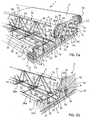
- FIGS 2b to 4 schematically illustrate additional alternative embodiments of the composite construction element 2 and of the floor structure 1 according to the present invention. These additional embodiments achieve both the advantageous technical effects of the embodiment described hereinbefore and the additional technical effects detailed hereinafter.
- the composite construction element 2 is a so-called joist element similar to the construction element illustrated in figures 1 and 2a except for a different configuration of the reinforcement metal structure 11 and of the transversal bars 32.
- the trestle-shaped reinforcement metal structure 11 is provided with a plurality of transversal stiffening elements 44, preferably metal rods, extending between the lateral stiffening rods 28, 29 which they are fixed to, for example by welding.
- the transversal stiffening elements 44 which are preferably extending along a direction substantially perpendicular to the longitudinal axis of the reinforcement metal structure 11. constitute as many means adapted to prevent that the reinforcement metal structure 11. in this case consisting of the trestle 24, may open under the load of the concrete casting 5 or as a consequence of other stresses directed, perpendicularly to the metal structure itself.
- the composite construction element 2 is a so-called floor element usable in the construction of a floor structure 1 including a plurality of construction elements arranged in side by side relationship with one another preferably without interposition or use of other elements of conventional type.
- the composite construction element 2 comprises an elongated body 3, substantially parallelepipedic, wherein a plurality of parallel recesses 42, of which only one is visible in figure 3a , is longitudinally defined.
- the elongated body 3 is laterally provided in turn with opposite sides 3a, 3b respectively provided with a groove 43 and a rib 44, having a mating shape, longitudinally extending along the entire length of the elongated body 3.
- the composite construction element 2 further comprises at least one reinforcing section bar, preferably a plurality of reinforcing section bars 38, 39 associated to the elongated body 3 made of expanded plastic material.
- the reinforcing section bars 38, 39 are longitudinally extending in the elongated body 3 at opposite parts of the longitudinal channel 4, preferably in a symmetrical manner with respect to the longitudinal center plane Y-Y of the composite construction element 2 defining the longitudinal axis of the elongated body 3.
- the reinforcing section bars 38, 39 are also longitudinally extending in the elongated body 3 along a direction substantially parallel to the aforementioned longitudinal axis.
- the reinforcing section bars 38, 39 are made of a material having suitable structural characteristics, for example cold-rolled and preferably galvanized steel, suitably shaped and having a thickness comprised between, for example, about 0.4 mm and about 0.8 mm.
- the reinforcing section bars 38, 39 are substantially Z-shaped and can be obtained by conventional bending and shearing operations, known per se , starting from a metal sheet having suitable width and thickness.
- the reinforcing section bars 38, 39 are provided with a central body 38a, 39a and with two lower 38b, 39b and, respectively, upper fins 38c, 39c extending from the opposite ends of the central body of the section bar.
- the reinforcing section bars 38, 39 are arranged in the elongated body 3 at a predetermined distance from one another; preferably, the distance d between the center line of the lower fins 38b, 39b - measured along a direction substantially perpendicular to the longitudinal axis of the elongated body 3 - is equal to about 300 nun.
- the reinforcing section bars are advantageously provided with a plurality of openings 41 formed in the central portion 38a, 39a thereof, comprised between the aforementioned fins 38b, 38c and 39b, 39c.
- the openings 41 carry out the dual advantageous function of lightening the reinforcing section bars 38, 39 and of allowing an even more intimate integration thereof in the mass of expanded plastic material.
- the mass of expanded plastic material is capable of interpenetrating with the reinforcing section bars 38, 39 during the molding operation, integrating and securely holding the reinforcing section bars 38, 39 in position in the elongated body 3 of the composite construction element 2.
- the aforementioned openings have a total area comprised between about 10% and about 40% of the total area of the reinforcing, section bar.
- the shape of the openings - obtainable in any manner known per se , such as for example by punching - is not critical; in any case, it is preferably circular for obvious reasons of construction simplicity.
- the openings have a diameter preferably comprised between about 15 mm and about 150 mm.
- the openings are pitchwise arranged in the central portion of the reinforcing section bar along the longitudinal center plane of the section bar itself.
- the pitch of the opening is comprised between about 80 and about 100 mm.
- the reinforcing section bars 38, 39 are advantageously provided with a lower portion - for example constituted by the lower fins 38b, 39b extending flush with and substantially parallel to the lower face 14 of the elongated body 3.
- the lower fins 38b, 39b carry out the function of providing a suitable supporting surface which a suitable rigid covering element, for example a plasterboard panel 40 fixed to the fins in a way known per se , for example by means of screws, can be fixed to or, in the alternative, which a suitable flexible covering element, such as for example a stretched lath for supporting at least one covering layer (not shown in figure 3a ), can be fixed to.
- a suitable rigid covering element for example a plasterboard panel 40 fixed to the fins in a way known per se , for example by means of screws
- a suitable flexible covering element such as for example a stretched lath for supporting at least one covering layer (not shown in figure 3a )
- the reinforcing section bars 38, 39 are longitudinally extending within the elongated body 3 along substantially the entire length thereof, and they are for example embedded in this body during the molding of the expanded plastic material.
- the reinforcing section bars 38, 39 are advantageously securely associated to the reinforcement metal structure 11 of the concrete casting by means of the transversal bars 32 extending through the longitudinal channel 4.
- the transversal bars 32 are fixed at their opposite ends to an upper portion - for example to the upper fins 38c, 39c - of the reinforcing section bars 38, 39.
- the composite construction element 2 advantageously achieves improved fire resistance characteristics since the covering elements, the plasterboard panels 40 associated to the lower face 14 of the elongated body 3, are securely held by the reinforcement metal structure 11 embedded in the concrete casting 5 by means of the reinforcing section bars 38, 39.
- the covering elements 40 do not detach from the composite construction element 2 even in the presence of a complete collapse of the elongated body 3 made of expanded plastic material.
- This alternative embodiment of the composite construction element 2 of the invention achieves both the advantageous technical effects of the previous embodiment and the additional technical effects achieved thanks to the presence of the reinforcing section bars 38, 39 and thanks to the stable association thereof to the reinforcement metal structure 11, in terms of higher stability and load bearing capacity and of fire resistance.
- the composite construction element 2 is a so-called floor element similar to the construction element illustrated in figure 3a except for a different configuration of the reinforcement metal structure 11 and of the transversal bars 32.
- the trestle-shaped reinforcement metal structure 11 is provided with a plurality of transversal stiffening elements 44, preferably metal rods, similar to the rods 44 illustrated with reference to the preferred embodiment of figure 2b .
- the technical effect of the transversal stiffening elements 44 is to prevent that the trestle 24 may open under the load of the casting 5 or as a consequence of other stresses directed perpendicularly to the trestle itself.
- the composite construction element 2 is a so-called joist element similar to the construction element illustrated in figures 1 and 2a except for the presence of suitably shaped reinforcing section bars.
- the composite construction element 2 comprises a pair of substantially C-shaped reinforcing section bars 45, 46 externally associated to a lower portion of the opposite sides 3a, 3b of the elongated body 3 made of expanded plastic material.
- the reinforcing section bars 45, 46 are longitudinally extending externally to the elongated body 3 along substantially its entire length.
- the reinforcing section bars 45, 46 can be associated to the elongated body 3 made of expanded plastic material also after the molding operations of the latter, which in this case may be carried out with less complex and less expensive equipment.
- the reinforcing section bars 45, 46 are provided with a lower portion, for example constituted by fins 45b, 46b, extending flush with and substantially parallel to the lower face 14 of the elongated body 3.
- the fins 45b, 46b carry out the function of providing a suitable supporting surface which a suitable covering element can be fixed to, for example a plasterboard panel 40 or, if desired, a lath for supporting at least one layer made of a suitable covering material similarly to what has been illustrated with reference to figures 1 and 2a .
- the composite construction element 2 is a so-called floor element comprising a different configuration of the hooking means of the reinforcement metal structure 11 and of the engagement elements defined in the elongated body 3 intended to cooperate with them.
- the elongated body 3 of the composite construction element 2 is laterally provided with opposite sides 3a, 3b each provided with a groove 47 and with a rib 48, having a mating shape, longitudinally extending along the entire length of the elongated body 3.
- the hooking means of the reinforcement metal structure 11 comprises a plurality of hooking portions 49 laterally extending at opposite parts of the reinforcement metal structure 11.
- the engagement elements defined in the elongated body 3 made of expanded plastic material cooperating with the hooking means 49 comprise a pair of longitudinal grooves 50 - only one of which is visible in figure 5 - formed in the elongated body 3 at opposite parts of the longitudinal channel 4.
- the elongated body 3 and the reinforcement metal structure 11 can be rigidly associated to each other by sliding drawer-wise one with respect to the other, for example by inserting the elongated body 3 onto the reinforcement metal structure 11 with a sliding movement guided by the engagement of the hooking portions 49 in the longitudinal grooves 50.
- the longitudinal grooves 50 define respective housing and sliding zones of the hooking portions 49 and are therefore preferably shaped so as to have a cross section substantially mating the cross section of the hooking portions 49 as illustrated in figure 5 .
- the hooking portions 49 and the longitudinal grooves 50 are substantially perpendicular to the longitudinal center plane Y-Y of the composite construction element 2.
- the composite construction element 2 comprises in this case a suitably shaped and preferably slab-shaped reinforcing element 51 adapted to reinforce at least an upper wall 52 of the longitudinal grooves 50 and longitudinally extending in the elongated body 3 substantially parallel to said upper wall.
- the hooking portions 49 of the reinforcement metal structure 11 may damage the elongated body 3 made of expanded plastic material, when the latter is subjected to stresses directed perpendicularly to the body itself, such as for example vertical loads, or during the reciprocal sliding between the elongated body 3 and the reinforcement metal structure 11.
- the reinforcing element 51 is constituted by a section bar having substantially the same shape as the longitudinal grooves 50 and integrated in the mass of expanded plastic material along the entire periphery of the grooves themselves.
- the reinforcing element 51 carries out the maximum protecting action of the inner walls of the longitudinal grooves 50 avoiding possible damages, whatever the direction of the stresses exerted by the hooking portions 49 may be.
- the reinforcement metal structure 11 is substantially constituted by a trestle 24 similar to that of the previous embodiments.
- the lateral stiffening rods 28, 29 of trestle 24 are in this case provided with a plurality of portions substantially shaped as an upturned V and extending along a direction substantially parallel to the longitudinal axis X-X of the reinforcement metal structure 11.
- the hooking portions 49 are therefore constituted by respectives loop portions laterally extending in a cantilevered fashion from the trestle 24 between the aforementioned substantially V-shaped portions.
- the hooking portions 49 of the trestle 24 are constituted by respective end portions 53a, 53b of a plurality of stiffening staples 53 shaped as an upturned V arranged astride of the upper rod 27.
- the aforementioned end portions 53a, 53b are laterally extending in a cantilevered fashion from the trestle 24 so as to achieve a technical effect similar to that of the loop portions of the lateral stiffening rods 28, 29 of the embodiment illustrated in figure 5 .
- the stiffening staples 53 are structurally independent from one mother and are fixed, for example by welding, to the upper longitudinal rod 27 of the reinforcement metal structure 11 at the vertex of the aforementioned V.
- the stiffening staples 53 are also fixed, for example by welding, to the lower longitudinal rods 25, 26 at their end portions 53a, 53b.
- the composite construction element 2 is a so-called floor element similar to the construction element illustrated in figure 5 except for the fact that it further comprises at least one reinforcing section bar, preferably a plurality of reinforcing section bars 54, 55, associated to the elongated body 3 made of expanded plastic material.
- the reinforcing section bars 54, 55 are longitudinally extending in the elongated body 3 at opposite parts of the longitudinal channel 4, preferably symmetrically with respect to the longitudinal center plane Y-Y of the elongated body 3 along a direction substantially parallel to the longitudinal axis defined by such plane.
- the reinforcing section bars 54, 55 are made of a material having suitable structural characteristics, for example cold-rolled and preferably galvanized steel, shaped in a suitable manner.
- the reinforcing section bars 54, 55 are substantially Z-shaped and can be obtained by conventional bending and shearing operations, known per se, starting from a metal sheet having suitable width and thickness.
- the reinforcing section bars 54, 55 are provided with a central body 54a, 55a and with two lower 54b, 55b and, respectively, upper fins 54c, 55c extending from opposite ends of the central body of the section bar.
- the reinforcing section bars 54, 55 are advantageously provided with a plurality of openings 56 formed in the central portion 54a, 55a thereof.
- the shape of the openings is not critical; in any case, it is preferably circular for obvious reasons of construction simplicity.
- the reinforcing section bars 54, 55 are advantageously provided with a lower portion - for example constituted by the lower fins 54b, 55b - extending flush with and substantially parallel to the lower face 14 of the elongated body 3.
- Such fins carry out the function of providing a suitable supporting surface which a suitable covering element, such as for example a lath for supporting at least one layer made of a suitable covering material or a rigid covering element, such as for example a plasterboard panel, can be fixed to.
- the reinforcing section bars 54, 55 are longitudinally extending in the elongated body 3 along substantially the entire length thereof, and they are for example embedded in this body during the molding of the expanded plastic material.
- the composite construction element 2 is a so-called floor element similar to the construction element illustrated in figure 5 except for a slightly different configuration of the hooking portions 49 laterally extending from the reinforcement metal structure 11, and of the longitudinal grooves 50 adapted to cooperate therewith.
- the composite construction element 2 comprises a pair of supporting section bars 57 fixed on the upper side of the hooking portions 49 of the reinforcement metal structure 11 and cooperating in abutment relationship with the upper wall 52 of the longitudinal grooves 50 formed in the elongated body 3 made of expanded plastic material.
- the supporting section bars 57 have a substantially U shaped cross-section.
- the upper wall 52 of the longitudinal grooves 50 and the supporting section bars 57 preferably have a substantially mating shape so as to minimize any possible reciprocal movements during the installation operations.
- the upper wall 52 of the longitudinal grooves 50 can be provided with a rib 58 having a mating shape adapted to cooperate with the supporting section bars 57.
- the composite construction element 2 is a so-called floor element similar to the construction element illustrated in figure 6 except for a slightly different configuration of the hooking portions 49 laterally extending from the reinforcement metal structure 11, of the longitudinal grooves 50 adapted to cooperate therewith and of the reinforcing section bars 54 and 55.
- the hooking portions 49 are inclined upwards and preferably form an angle ⁇ comprised between about 5° and about 15° with respect to a plane perpendicular to the longitudinal center plane Y-Y of the composite construction element 2, instead of being substantially perpendicular to the longitudinal center plane Y-Y of the composite construction element 2 as in the embodiments of figures 5-7 .
- the longitudinal grooves 50 adapted to cooperate with the hooking portions 49 are formed in the elongated body 3 so as to have a similar inclination with respect to the longitudinal center plane -Y-Y of the composite construction element 2.
- this configuration of parts allows to accomplish an improved resistance of the composite construction element 2 to a decentralized load due to an increased bending resistance achieved thanks to the supporting action exerted by the inclined hooking portions 49.
- the reinforcing section bars 54 and 55 are provided with a central body 54a, 55a and with two lower 54b, 55b and, respectively, upper fins 54c, 55c extending from the opposite ends of the central body of the section bar.
- the upper fins 54c, 55c exhibit the peculiarity of extending flush with and substantially parallel to the upper wall 52 of the longitudinal grooves 50 formed in the elongated body 3 made of expanded plastic material, so as to form as many slab-shaped reinforcing elements of the wall 52 adapted to prevent damages thereof when the construction element 2 is stressed along the perpendicular direction (for example vertical).
- the upper fins 54c, 55c preferably form an angle a' comprised between about 5° and about 15° with respect to a plane perpendicular to the longitudinal center plane Y-Y of the composite construction element 2.
- the lower fins 54b and 55b of the reinforcing section bars 54 and 55 are provided with an initial portion extending flush with and substantially parallel to the lower face 14 of the elongated body 3 and with an end portion substantially perpendicular to the aforementioned initial portion.
- such initial portion carries out the function of providing a suitable supporting surface which a covering element, for example a lath for supporting at least one layer made of a suitable covering material or a rigid panel, can be fixed to, whereas the end portion increases the reinforcing action carried out by the reinforcing section bars 54 and 55 under bending loads.
- a covering element for example a lath for supporting at least one layer made of a suitable covering material or a rigid panel
- the composite construction element 2 is a so-called floor element similar to the construction element illustrated in figure 8 except for a slightly different configuration of the reinforcing section bars 54 and 55.
- the reinforcing section bars are provided with upper fins 54c, 55c forming an angle of predetermined value with respect to a plane perpendicular to the longitudinal center plane Y-Y of the composite construction element 2.
- such an angle has the same value as the angle ⁇ ' and is comprised between about 5° and about 15° with respect to a plane perpendicular to the longitudinal center plane Y-Y of the composite construction element 2.
- the central body 54a, 55b of the reinforcing section bars 54 and 55 forms an angle ⁇ comprised between about 30° and about 45° with respect to a plane perpendicular to the longitudinal center plane Y-Y of the composite construction element 2.
- the composite construction element 2 is a so-called floor element similar to the construction element illustrated in figure 5 except for the fact that it further comprises at least one reinforcing section bar, preferably a plurality of reinforcing section bars 38, 39 associated to the elongated body 3 made of expanded plastic material.
- the reinforcing section bars 38, 39 are similar to and substantially achieve the same technical effects of the reinforcing section bars illustrated with reference to the embodiments of figures 3a and 3b .
- the lower fins 38b, 39b of the reinforcing section bars 38, 39 carry out the advantageous function of providing a suitable supporting surface which a suitable rigid covering element, such as for example a panel of a rigid material, or alternatively a suitable flexible covering element, such as for example a stretched lath for supporting at least one covering layer (not shown in figure 10 ), can be fixed to.
- a suitable rigid covering element such as for example a panel of a rigid material
- a suitable flexible covering element such as for example a stretched lath for supporting at least one covering layer (not shown in figure 10 )
- the reinforcing section bars 38, 39 are advantageously securely associated to the reinforcement metal structure 11 of the concrete casting by means of the hooking portions 49 laterally extending in a cantilevered fashion from the trestle 24.
- the upper fins 38c, 39c of the reinforcing section bars 38, 39 are fixed to the hooking portions 49, for example by wielding.
- the composite construction, element 2 advantageously achieves improved fire resistance characteristics since the covering elements associated to the lower face 14 of the elongated body 3, are securely held by the reinforcement metal structure 11 embedded in the concrete casting 5 by means of the reinforcing section bars 38, 39.
- the composite construction element 2 is manufactured by means of continuous operations by first- manufacturing a reinforcement metal structure 11 provided with the reinforcing section bars 38, 39 and then by integrating the latter in the mass of expanded plastic material which constitutes the elongated body 3 during the molding step thereof.
- the hooking portions 49 of the trestle 24 are constituted by respective end portions 53a, 53b of a plurality of stiffening staples 53 shaped as an upturned V arranged astride of the upper rod 27.
- the stiffening staples 53 are similar and substantially achieve the same technical effects of the staples illustrated with reference to the embodiment of the reinforcing metal structure 11 of figure 5a .
- the reinforcement metal structure 11 comprises the reinforcing section bars 38, 39 securely associated thereto by means of the end portions 53a, 53b of the stiffening staples 53.
- the composite construction element 2 is a so-called floor element similar to that illustrated in figure 10 , from which it differs for the presence of at least one transversal channel 59, preferably, a plurality of transversal channels 59 suitably spaced from one another in the longitudinal direction, formed in the elongated body 3 made of expanded plastic material and open on the upper side for housing the concrete casting 5.
- the composite construction element 2 further comprises an additional reinforcement metal structure 11' of the casting, preferably a plurality of reinforcement metal structures 11', housed in the aforementioned transversal channels.
- this composite construction element 2 allows to increase the load bearing characteristics of the floor structure 1 or to reduce the overall thickness of the floor structure 1 if the load bearing characteristics are maintained unaltered.
- the floor structure 1 comprises a plurality of composite construction elements 2, in this case forming as many floor elements as illustrated, for example, in figures 3a, 3b , and 5-10 , laid at their opposite ends 12 on respective supporting structures of a building and arranged in side by side relationship with respect to one another.
- These supporting structures can for example be constituted by a beam 60 and of load bearing walls 61 of the building being erected.
- the beam 60 is a so-called “whole-thickness truss beam", that is, has a thickness substantially equal to the thickness of the floor structure 1 and comprises a base 62, for example constituted by a metal or cement slab, and a supporting and reinforcing metal structure 63.
- the metal structure 63 is substantially constituted by a reticular trestle known per se
- the beam 60 is further provided at a lower side with a covering slab 64 made of expanded plastic material fixed to the base 62 by means of two substantially C-shaped section bars 65, 66.
- the thickness of the covering slab 64 is substantially equal to the distance between the free ends 12 of the reinforcement metal structures 11 and the lower face 14 of the elongated body 3 made of expanded plastic material of the composite construction elements 2.
- the lower face 14 of the elongated body 3 made of expanded plastic material in fact lies in a plane which is located below the lower face of the bare whole-thickness truss beam, that is, without the covering slab 64.
- the thickness of the covering made of expanded plastic material of the lower face of the floor structure 1 can be adjusted as desired by simply adjusting the thickness of the portion of the elongated body 3 made of plastic material extending below the longitudinal channel 4 wherein the reinforcement metal structure 11 is housed and the thickness of the covering slab 64.
Landscapes
- Engineering & Computer Science (AREA)
- Architecture (AREA)
- Civil Engineering (AREA)
- Structural Engineering (AREA)
- Physics & Mathematics (AREA)
- Electromagnetism (AREA)
- Reinforcement Elements For Buildings (AREA)
- Floor Finish (AREA)
- Compositions Of Macromolecular Compounds (AREA)
- Panels For Use In Building Construction (AREA)
- Building Environments (AREA)
Priority Applications (1)
| Application Number | Priority Date | Filing Date | Title |
|---|---|---|---|
| PL05736863T PL1756375T3 (pl) | 2004-05-11 | 2005-05-10 | Nośny element konstrukcyjny w szczególności do wytwarzania podłóg budynków oraz konstrukcji podłóg zawierających taki element |
Applications Claiming Priority (2)
| Application Number | Priority Date | Filing Date | Title |
|---|---|---|---|
| IT000941A ITMI20040941A1 (it) | 2004-05-11 | 2004-05-11 | Elemento costruttivo portante in particolare per la realizzazione di solai di edifici e struttura di solaio incorporante tale elemento |
| PCT/IB2005/001364 WO2005108700A1 (en) | 2004-05-11 | 2005-05-10 | Load bearing construction element in particular for manufacturing building floors and floor structure incorporating such element |
Publications (2)
| Publication Number | Publication Date |
|---|---|
| EP1756375A1 EP1756375A1 (en) | 2007-02-28 |
| EP1756375B1 true EP1756375B1 (en) | 2012-01-04 |
Family
ID=34972383
Family Applications (1)
| Application Number | Title | Priority Date | Filing Date |
|---|---|---|---|
| EP05736863A Expired - Lifetime EP1756375B1 (en) | 2004-05-11 | 2005-05-10 | Load bearing construction element in particular for manufacturing building floors and floor structure incorporating such element |
Country Status (11)
| Country | Link |
|---|---|
| US (1) | US7784235B2 (pl) |
| EP (1) | EP1756375B1 (pl) |
| CN (1) | CN1954128B (pl) |
| AT (1) | ATE540176T1 (pl) |
| CA (1) | CA2564704A1 (pl) |
| ES (1) | ES2379635T3 (pl) |
| IT (1) | ITMI20040941A1 (pl) |
| MX (1) | MXPA06012941A (pl) |
| PL (1) | PL1756375T3 (pl) |
| RU (1) | RU2352732C2 (pl) |
| WO (1) | WO2005108700A1 (pl) |
Families Citing this family (56)
| Publication number | Priority date | Publication date | Assignee | Title |
|---|---|---|---|---|
| US20050262786A1 (en) * | 2002-03-06 | 2005-12-01 | Messenger Harold G | Concrete foundation wall with a low density core and carbon fiber and steel reinforcement |
| US8997420B2 (en) * | 2004-11-29 | 2015-04-07 | Victor Amend | Reinforced insulated forms for constructing concrete walls and floors |
| JP4264462B2 (ja) * | 2007-01-04 | 2009-05-20 | 新日本製鐵株式会社 | 床構造 |
| US20080276559A1 (en) * | 2007-05-11 | 2008-11-13 | Oldcastle Precast, Inc. | Low Density Concrete Wall Panel With Reinforced Insulation Members |
| ITVA20070053A1 (it) * | 2007-06-19 | 2008-12-20 | Plastedil Sa | Manufatto composito per la costruzione di solai |
| ITMI20071455A1 (it) * | 2007-07-19 | 2009-01-20 | Leone Lucio | Travi migliorate per l'armatura del calcestruzzo e metodo per il loro collegamento con pilastri per dare continuita da campata a campata |
| ITBO20080144A1 (it) * | 2008-03-04 | 2009-09-05 | Angelo Candiracci | Pannello per la realizzazione di un solaio o simile. |
| EP2146017A1 (de) * | 2008-07-18 | 2010-01-20 | Beletto AG | Bauteil für Decken oder Dächer sowie Verfahren zum Herstellen eines Bauteils |
| IT1390922B1 (it) * | 2008-07-30 | 2011-10-19 | Tecnostrutture S R L | Trave portante a struttura mista |
| ITPN20080092A1 (it) * | 2008-12-16 | 2010-06-17 | Pontarolo Engineering Spa | Elemento costruttivo autoportante adatto per la costruzione di solai in cemento armato. |
| IT1392597B1 (it) * | 2009-01-07 | 2012-03-09 | Tecnostrutture S R L | Trave portante a struttura mista |
| US20100193662A1 (en) * | 2009-02-04 | 2010-08-05 | Peter Juen | Form panel system for poured concrete |
| KR100971736B1 (ko) * | 2009-04-03 | 2010-07-21 | 이재호 | 상하 각각 이중 앵커리지 기능을 갖는 전단보강재 |
| ES1071064Y (es) * | 2009-07-17 | 2010-03-16 | Oliver Jose Ramon Noales | Forjado para plantas de construccion |
| WO2011017704A2 (en) * | 2009-08-07 | 2011-02-10 | Garrett Michael D | Deck block |
| IT1396675B1 (it) * | 2009-10-23 | 2012-12-14 | Rexpol Srl | Cassero a perdere per solai ad alta resistenza al fuoco |
| WO2011073731A1 (en) * | 2009-12-17 | 2011-06-23 | Marco Manganello | Disposable formwork for making concrete floors |
| ES2380857B1 (es) * | 2010-05-31 | 2013-04-15 | Imat Centre Tecnologic De La Construccio | Procedimiento de fabricacion de elementos de forjado bidireccionales prefabricados de hormigon armado y estructura de forjado bidireccional obtenida con dichos elementos |
| US8220219B2 (en) | 2010-12-03 | 2012-07-17 | Martter Richard P | Reinforcing assembly, and reinforced concrete structures using such assembly |
| US8549813B2 (en) | 2010-12-03 | 2013-10-08 | Richard P. Martter | Reinforcing assembly and reinforced structure using a reinforcing assembly |
| US20140059967A1 (en) * | 2010-12-03 | 2014-03-06 | Richard P. Martter | Reinforcing assembly having working members with non-planar tips |
| ITUD20110048A1 (it) * | 2011-03-31 | 2012-10-01 | Panebianco Amalia | Pannello strutturale prefabbricato per solai |
| AT511220B1 (de) * | 2011-04-08 | 2013-01-15 | Cree Gmbh | Deckenelement zur ausbildung von gebäudedecken |
| AR090164A1 (es) * | 2012-02-27 | 2014-10-22 | Hengelhoef Concrete Joints Mfg Nv | Junta de expansion |
| ITTO20120370A1 (it) * | 2012-04-26 | 2013-10-27 | Bazzica Engineering S R L | Solaio modulare con cassero a perdere |
| ITMI20120730A1 (it) * | 2012-05-02 | 2013-11-03 | Luscari Salvatore Lembo | Nuovo blocco o pannello auto-portante, a struttura alleggerita, in particolare per la realizzazione di solai in cemento armato da gettare in opera |
| CN104641055A (zh) * | 2012-06-29 | 2015-05-20 | 沃尔夫冈·阿道夫·宾德 | 建造系统及方法 |
| MD678Z (ro) * | 2013-01-21 | 2014-04-30 | Николай БОГУСЛАВСКИЙ | Planşeu parţial prefabricat |
| EP2868826A1 (de) * | 2013-10-31 | 2015-05-06 | Basf Se | Betonelement umfassend einen Schallabsorber |
| US9371650B2 (en) * | 2014-03-24 | 2016-06-21 | Manuel R. Linares, III | Precast concrete sandwich panels and system for constructing panels |
| JP6371154B2 (ja) * | 2014-07-23 | 2018-08-08 | ケンテック株式会社 | 鉄筋構造材 |
| US10087642B2 (en) * | 2016-01-11 | 2018-10-02 | Robert Montoya | Screen grid insulated concrete form panel system and method for construction and building |
| AT518496B1 (de) * | 2016-04-13 | 2021-12-15 | Hans Ulrich Terkl | Verfahren zur Herstellung eines Verbundelementes sowie Verbundelement |
| CN106639101A (zh) * | 2016-05-26 | 2017-05-10 | 湖北大成空间科技股份有限公司 | 一种装配式空腔叠合楼板施工方法 |
| CN106639098A (zh) * | 2016-05-26 | 2017-05-10 | 湖北大成空间科技股份有限公司 | 一种装配式空腔楼板 |
| CN106677395A (zh) * | 2016-05-26 | 2017-05-17 | 湖北大成空间科技股份有限公司 | 一种装配式空腔楼板施工方法 |
| CN106639092A (zh) * | 2016-05-26 | 2017-05-10 | 湖北大成空间科技股份有限公司 | 一种装配式空腔叠合楼板 |
| EP3289148A1 (en) * | 2016-06-09 | 2018-03-07 | Mirkhani, Seyed Soroush | A slab filler |
| EP4491821A3 (en) | 2016-06-23 | 2025-02-26 | Hickory Design Pty Ltd | Methods and apparatus for constructing multi-storey buildings |
| US10119276B2 (en) | 2016-07-15 | 2018-11-06 | Richard P. Martter | Reinforcing assemblies having downwardly-extending working members on structurally reinforcing bars for concrete slabs or other structures |
| US11220822B2 (en) | 2016-07-15 | 2022-01-11 | Conbar Systems Llc | Reinforcing assemblies having downwardly-extending working members on structurally reinforcing bars for concrete slabs or other structures |
| AT519761B1 (de) * | 2017-03-17 | 2018-10-15 | Trumpf Maschinen Austria Gmbh & Co Kg | Biegeschritt-Auswahlverfahren, ausgeführt auf einem Steuerungssystem einer Biegemaschine |
| US10870985B2 (en) * | 2017-05-03 | 2020-12-22 | Illinois Tool Works Inc. | Concrete slab load transfer and connection apparatus and method of employing same |
| TWI634255B (zh) * | 2017-09-11 | 2018-09-01 | 潤弘精密工程事業股份有限公司 | 施作彼此銜接之複數梁的方法 |
| US11598091B2 (en) * | 2017-11-12 | 2023-03-07 | Seyed Soroush Mirkhani | Slab fillers and methods for implementing fillers in two-way concrete slabs for building structures |
| US11242689B2 (en) * | 2018-03-29 | 2022-02-08 | Bailey Metal Products Limited | Floor panel system |
| US11072925B2 (en) * | 2018-12-12 | 2021-07-27 | Dalian University Of Technology | Rapid construction method for flush assembly of the prefabricated steel beam and the floor slab |
| US11203840B2 (en) | 2019-06-25 | 2021-12-21 | Illinois Tool Works Inc. | Method and apparatus for two-lift concrete flatwork placement |
| FI129949B (fi) * | 2019-10-16 | 2022-11-30 | Finnfoam Oy | Lämmöneristelevy ja sen käyttö |
| CN113027020B (zh) * | 2019-12-24 | 2023-01-03 | 贺州通号装配式建筑有限公司 | 一种预制楼板安装节点及其施工方法 |
| CN112382164B (zh) * | 2020-06-18 | 2022-10-28 | 杭州中宙建工集团有限公司 | 一种适用于装配式建筑构件制作预埋节点的培训装置 |
| JP7770739B2 (ja) * | 2021-07-14 | 2025-11-17 | 三菱地所株式会社 | 複合型デッキプレート |
| US12134899B2 (en) * | 2022-01-11 | 2024-11-05 | Isostruc Llc | Rigid foam, continuous raised floor structure without wooden supports |
| CN115627846B (zh) * | 2022-11-08 | 2023-07-14 | 中交一公局集团有限公司 | 一种装配式叠合板的施工方法及后浇带结构 |
| US12553236B2 (en) * | 2023-10-31 | 2026-02-17 | Sharif Haddad | Insulated hollow core concrete forming system for walls and slabs |
| US20250347111A1 (en) * | 2024-05-08 | 2025-11-13 | Onx, Inc. | Method and arrangement for forming precast concrete panels |
Citations (2)
| Publication number | Priority date | Publication date | Assignee | Title |
|---|---|---|---|---|
| FR2630480A1 (fr) * | 1988-04-26 | 1989-10-27 | Cote Francois | Solive autoportante et coffrante |
| EP0870883A2 (en) * | 1997-04-11 | 1998-10-14 | Gruppo Effe 2 SpA | Prefabricated joist for floors and/or lintels made of a framework and brick, and brick base for said joist |
Family Cites Families (42)
| Publication number | Priority date | Publication date | Assignee | Title |
|---|---|---|---|---|
| US1215872A (en) * | 1913-07-07 | 1917-02-13 | Cipriano Salvatierra-Iriarte | Skeleton frame for armored concrete posts or masts. |
| US1941211A (en) * | 1930-04-28 | 1933-12-26 | Inglee Lewis | Structural floor |
| US1885496A (en) * | 1931-09-19 | 1932-11-01 | Frederick M Venzie | Building construction |
| US2260425A (en) * | 1938-04-21 | 1941-10-28 | John J Widmayer | Plastic floor or roof |
| BE564912A (pl) * | 1957-02-18 | |||
| US3104600A (en) * | 1959-05-14 | 1963-09-24 | Bethlehem Steel Corp | Road joint assembly |
| US3302360A (en) * | 1963-01-09 | 1967-02-07 | Bjerking Sven-Erik | Method of reinforcing concrete floors and the like, and a reinforcing element therefor |
| US3347007A (en) * | 1964-12-18 | 1967-10-17 | Jesse R Hale | Embedded spaced truss structures |
| BE791160A (fr) | 1972-01-03 | 1973-05-09 | Beecham Group Ltd | Nouveaux cephemes substitues |
| FR2166335A1 (en) * | 1972-01-05 | 1973-08-17 | Sattanino Jean Pierre | Prefabricated flooring components - using profiled sections of insulating materials in conjunction with cast concrete |
| DE2234941C2 (de) * | 1972-07-15 | 1983-01-13 | Edmund Dipl.-Ing.Dipl.-Wirtsch.-Ing.Dr.-Ing. 6228 Eltville Wagner | Bewehrung mit einem fachwerkartigen Träger |
| US4272230A (en) * | 1975-09-05 | 1981-06-09 | Solai Vignola Di Faviani Orlando Ec Societa | Slip form for building components |
| FR2322984A1 (fr) * | 1975-09-05 | 1977-04-01 | Solai Vignola Fabiani Orlando | Elements de construction prefabriques en materiau expanse-ciment, leur procede de prefabrication et installations appropriees |
| FR2361512A1 (fr) * | 1976-08-12 | 1978-03-10 | Joannes Andre | Panneau de construction prefabrique et procede de fabrication |
| US4472919A (en) * | 1982-05-19 | 1984-09-25 | Con-Tex Elements, Inc. | Prefabricated building panel |
| IT8261999U1 (it) * | 1982-10-06 | 1984-04-06 | Spil Impianti Spa | Travetto laterocementizio armato |
| US4611450A (en) * | 1983-09-16 | 1986-09-16 | Chen Kai Nan | Multi-reinforced construction panel |
| US4614013A (en) * | 1984-02-21 | 1986-09-30 | David Stevenson | Method of forming a reinforced structural building panel |
| AU586425B2 (en) | 1985-05-17 | 1989-07-13 | Radva Corporation | Insulating building panel for column and beam structure |
| DE3610030C1 (de) * | 1986-03-25 | 1987-02-05 | Rapp Albert Bruno | Bauelement fuer Hochbauwerke |
| KR910006579A (ko) * | 1989-09-07 | 1991-04-29 | 미야자끼 아끼라 | 트러스 및 이것에 의하여 강화된 콘크리트 부품 슬라브 |
| FR2662730B1 (fr) * | 1990-05-29 | 1992-09-25 | Eurostyrene Sarl | Procede de fabrication de hourdis autocoffrants et isolants, dispositif pour la mise en óoeuvre de ce procede et hourdis ainsi obtenus. |
| EP0494061B1 (en) | 1991-01-03 | 1996-06-12 | José Antonio Sainz de la Maza del Castillo | A method and elements for assembling a non-recoverable formwork |
| AT396274B (de) * | 1991-04-23 | 1993-07-26 | Avi Alpenlaendische Vered | Bewehrungskoerper fuer eine deckenplatte |
| US5235791A (en) * | 1992-04-28 | 1993-08-17 | Yaguchi Kenzai Khakko Co., Ltd. | Deck plate |
| ES2068110B1 (es) * | 1992-12-18 | 1996-12-16 | Herman Storch | Una malla estructural, para ser utilizada en componentes resistentes de sistemas constructivos. |
| RU2054507C1 (ru) * | 1993-07-29 | 1996-02-20 | Государственный центральный научно-исследовательский и проектно-экспериментальный институт комплексных проблем строительных конструкций и сооружений им.В.А.Кучеренко | Способ изготовления термоармопакета стенового ограждения |
| US5465538A (en) * | 1993-09-07 | 1995-11-14 | Powers, Jr.; John | Prefabricated lintel |
| IT1275312B (it) * | 1995-06-06 | 1997-08-05 | Plastedil Sa | Apparecchiatura per la formatura di un elemento continuo in materia plastica espansa |
| US6298622B1 (en) * | 1996-10-15 | 2001-10-09 | Plastedil, S.A. | Self-supporting construction element of expanded plastics, in particular for manufacturing floor elements and walls of buildings in general |
| KR200152480Y1 (ko) * | 1997-02-28 | 1999-07-15 | 조세훈 | 철근콘크리트 슬래브의 데크패널 |
| US5884442A (en) * | 1997-03-28 | 1999-03-23 | Structural Systems Ltd. | Composite joist and concrete panel assembly |
| JP2976023B1 (ja) * | 1998-05-14 | 1999-11-10 | 博 稲葉 | 複合建材及びその製造方法 |
| US6244008B1 (en) * | 1999-07-10 | 2001-06-12 | John Fullarton Miller | Lightweight floor panel |
| IT1316776B1 (it) * | 2000-02-18 | 2003-05-12 | Sergio Zambelli | Pannello prefabbricato in calcestruzzo per la realizzazione di solaiin costruzioni civili o industriali |
| CN2460645Y (zh) * | 2000-12-18 | 2001-11-21 | 陈耀宗 | 具不燃性防火网路高架地板 |
| ITCR20020015A1 (it) * | 2002-09-11 | 2004-03-12 | Ezio Ferrari | Elemento metallico o in altro materiale per l'esatto |
| US6955014B2 (en) * | 2002-11-07 | 2005-10-18 | Fabcon, Inc. | Insulated concrete cast panels with voids in billits |
| US20060137282A1 (en) * | 2002-12-19 | 2006-06-29 | Anvick Theodore E | Anvick aperture device and method of forming and using same |
| ITBO20030046A1 (it) * | 2003-02-03 | 2004-08-04 | Coperlegno Srl | Elementi prefabbricati per la realizzazione di solai pavimenti |
| DE102005045283B4 (de) * | 2005-09-22 | 2014-05-15 | Pfeiffer Vacuum Gmbh | Vakuumpumpsystem |
| US7810293B2 (en) * | 2006-08-15 | 2010-10-12 | Gibbar James H | Multiple layer polymer foam and concrete system for forming concrete walls, panels, floors, and decks |
-
2004
- 2004-05-11 IT IT000941A patent/ITMI20040941A1/it unknown
-
2005
- 2005-05-10 RU RU2006138681/03A patent/RU2352732C2/ru active
- 2005-05-10 MX MXPA06012941A patent/MXPA06012941A/es active IP Right Grant
- 2005-05-10 ES ES05736863T patent/ES2379635T3/es not_active Expired - Lifetime
- 2005-05-10 EP EP05736863A patent/EP1756375B1/en not_active Expired - Lifetime
- 2005-05-10 CN CN2005800151852A patent/CN1954128B/zh not_active Expired - Lifetime
- 2005-05-10 WO PCT/IB2005/001364 patent/WO2005108700A1/en not_active Ceased
- 2005-05-10 CA CA002564704A patent/CA2564704A1/en not_active Abandoned
- 2005-05-10 AT AT05736863T patent/ATE540176T1/de active
- 2005-05-10 PL PL05736863T patent/PL1756375T3/pl unknown
- 2005-05-10 US US11/125,089 patent/US7784235B2/en active Active
Patent Citations (2)
| Publication number | Priority date | Publication date | Assignee | Title |
|---|---|---|---|---|
| FR2630480A1 (fr) * | 1988-04-26 | 1989-10-27 | Cote Francois | Solive autoportante et coffrante |
| EP0870883A2 (en) * | 1997-04-11 | 1998-10-14 | Gruppo Effe 2 SpA | Prefabricated joist for floors and/or lintels made of a framework and brick, and brick base for said joist |
Also Published As
| Publication number | Publication date |
|---|---|
| MXPA06012941A (es) | 2007-04-25 |
| RU2006138681A (ru) | 2008-06-20 |
| CN1954128B (zh) | 2012-10-24 |
| ATE540176T1 (de) | 2012-01-15 |
| CA2564704A1 (en) | 2005-11-17 |
| US20060185280A1 (en) | 2006-08-24 |
| CN1954128A (zh) | 2007-04-25 |
| ES2379635T3 (es) | 2012-04-30 |
| EP1756375A1 (en) | 2007-02-28 |
| US7784235B2 (en) | 2010-08-31 |
| PL1756375T3 (pl) | 2012-06-29 |
| RU2352732C2 (ru) | 2009-04-20 |
| WO2005108700A1 (en) | 2005-11-17 |
| ITMI20040941A1 (it) | 2005-11-12 |
Similar Documents
| Publication | Publication Date | Title |
|---|---|---|
| EP1756375B1 (en) | Load bearing construction element in particular for manufacturing building floors and floor structure incorporating such element | |
| US8006450B2 (en) | Composite floor structure with a protruding bar upper portion in a floor element groove | |
| US7331149B2 (en) | Drywall backing apparatus and method of installing same | |
| US5809725A (en) | Sectional nog structure for fastening a covering element to a foamed plastic slab and construction element incorporating said structure | |
| EP0434869B1 (en) | Steel stud and precast panel | |
| HK1004759B (en) | Steel stud and precast panel | |
| US20060075701A1 (en) | Composite construction element, in particular for manufacturing floor structures and wall structures for buildings and method for manufacturing the same | |
| CA2300831C (en) | Wooden i-beam and wooden structural beam and bridging assembly | |
| EP0693597A1 (en) | Modular dowel assembly for fixing a lining element to a panel of an expanded plastic material and structural element incorporating said assembly | |
| US7814719B2 (en) | Self-supporting construction element made of expanded plastic material, in particular for manufacturing building floors and floor structure incorporating such element | |
| GB1579465A (en) | Lintel for supporting either courses of brickwork over wall openings or brick facades or the like | |
| EP1766150B1 (en) | Self-supporting construction element made of expanded plastic material, in particular for manufacturing building floors and floor structure incorporating such element | |
| EP2270287A1 (en) | A building assembly with a corner profile for an insulating building system | |
| GB2365456A (en) | Construction panel | |
| EP1799928A1 (en) | Improved floor structure | |
| RU2369699C2 (ru) | Композиционный строительный элемент и способ его изготовления | |
| KR102533647B1 (ko) | 지붕 시공용 이중 아치패널 조립체 | |
| DK2449185T3 (en) | ADDITIONAL INSULATION SYSTEM AND A PROCEDURE FOR INSULATING A FACADE | |
| CA1077735A (en) | Building construction, particularly ceilings and floors | |
| JPH09170284A (ja) | 耐力壁パネル及び耐力壁構造 | |
| Ajay et al. | Systems-an Analytical Approach | |
| MXPA03012072A (es) | Elemento estructural para la construccion de edificios. | |
| KR20000012430U (ko) | 보강재를 구비하고 초기인장력이 가해진 스틸스터드 | |
| KR200220925Y1 (ko) | 경량패널용 받침레일 | |
| EP1884604A2 (en) | Self-supporting metal beam for doors and windows |
Legal Events
| Date | Code | Title | Description |
|---|---|---|---|
| PUAI | Public reference made under article 153(3) epc to a published international application that has entered the european phase |
Free format text: ORIGINAL CODE: 0009012 |
|
| 17P | Request for examination filed |
Effective date: 20061205 |
|
| AK | Designated contracting states |
Kind code of ref document: A1 Designated state(s): AT BE BG CH CY CZ DE DK EE ES FI FR GB GR HU IE IS IT LI LT LU MC NL PL PT RO SE SI SK TR |
|
| DAX | Request for extension of the european patent (deleted) | ||
| GRAP | Despatch of communication of intention to grant a patent |
Free format text: ORIGINAL CODE: EPIDOSNIGR1 |
|
| GRAS | Grant fee paid |
Free format text: ORIGINAL CODE: EPIDOSNIGR3 |
|
| GRAA | (expected) grant |
Free format text: ORIGINAL CODE: 0009210 |
|
| AK | Designated contracting states |
Kind code of ref document: B1 Designated state(s): AT BE BG CH CY CZ DE DK EE ES FI FR GB GR HU IE IS IT LI LT LU MC NL PL PT RO SE SI SK TR |
|
| REG | Reference to a national code |
Ref country code: GB Ref legal event code: FG4D |
|
| REG | Reference to a national code |
Ref country code: CH Ref legal event code: EP |
|
| REG | Reference to a national code |
Ref country code: AT Ref legal event code: REF Ref document number: 540176 Country of ref document: AT Kind code of ref document: T Effective date: 20120115 |
|
| REG | Reference to a national code |
Ref country code: IE Ref legal event code: FG4D |
|
| REG | Reference to a national code |
Ref country code: DE Ref legal event code: R096 Ref document number: 602005031977 Country of ref document: DE Effective date: 20120308 |
|
| REG | Reference to a national code |
Ref country code: ES Ref legal event code: FG2A Ref document number: 2379635 Country of ref document: ES Kind code of ref document: T3 Effective date: 20120430 |
|
| REG | Reference to a national code |
Ref country code: NL Ref legal event code: VDEP Effective date: 20120104 |
|
| PG25 | Lapsed in a contracting state [announced via postgrant information from national office to epo] |
Ref country code: SI Free format text: LAPSE BECAUSE OF FAILURE TO SUBMIT A TRANSLATION OF THE DESCRIPTION OR TO PAY THE FEE WITHIN THE PRESCRIBED TIME-LIMIT Effective date: 20120104 |
|
| LTIE | Lt: invalidation of european patent or patent extension |
Effective date: 20120104 |
|
| REG | Reference to a national code |
Ref country code: PL Ref legal event code: T3 |
|
| PG25 | Lapsed in a contracting state [announced via postgrant information from national office to epo] |
Ref country code: BG Free format text: LAPSE BECAUSE OF FAILURE TO SUBMIT A TRANSLATION OF THE DESCRIPTION OR TO PAY THE FEE WITHIN THE PRESCRIBED TIME-LIMIT Effective date: 20120404 Ref country code: NL Free format text: LAPSE BECAUSE OF FAILURE TO SUBMIT A TRANSLATION OF THE DESCRIPTION OR TO PAY THE FEE WITHIN THE PRESCRIBED TIME-LIMIT Effective date: 20120104 Ref country code: IS Free format text: LAPSE BECAUSE OF FAILURE TO SUBMIT A TRANSLATION OF THE DESCRIPTION OR TO PAY THE FEE WITHIN THE PRESCRIBED TIME-LIMIT Effective date: 20120504 Ref country code: BE Free format text: LAPSE BECAUSE OF FAILURE TO SUBMIT A TRANSLATION OF THE DESCRIPTION OR TO PAY THE FEE WITHIN THE PRESCRIBED TIME-LIMIT Effective date: 20120104 Ref country code: LT Free format text: LAPSE BECAUSE OF FAILURE TO SUBMIT A TRANSLATION OF THE DESCRIPTION OR TO PAY THE FEE WITHIN THE PRESCRIBED TIME-LIMIT Effective date: 20120104 |
|
| PGFP | Annual fee paid to national office [announced via postgrant information from national office to epo] |
Ref country code: DE Payment date: 20120529 Year of fee payment: 8 |
|
| PG25 | Lapsed in a contracting state [announced via postgrant information from national office to epo] |
Ref country code: PT Free format text: LAPSE BECAUSE OF FAILURE TO SUBMIT A TRANSLATION OF THE DESCRIPTION OR TO PAY THE FEE WITHIN THE PRESCRIBED TIME-LIMIT Effective date: 20120504 Ref country code: GR Free format text: LAPSE BECAUSE OF FAILURE TO SUBMIT A TRANSLATION OF THE DESCRIPTION OR TO PAY THE FEE WITHIN THE PRESCRIBED TIME-LIMIT Effective date: 20120405 Ref country code: FI Free format text: LAPSE BECAUSE OF FAILURE TO SUBMIT A TRANSLATION OF THE DESCRIPTION OR TO PAY THE FEE WITHIN THE PRESCRIBED TIME-LIMIT Effective date: 20120104 |
|
| PGFP | Annual fee paid to national office [announced via postgrant information from national office to epo] |
Ref country code: FR Payment date: 20120607 Year of fee payment: 8 Ref country code: PL Payment date: 20120523 Year of fee payment: 8 |
|
| PG25 | Lapsed in a contracting state [announced via postgrant information from national office to epo] |
Ref country code: CY Free format text: LAPSE BECAUSE OF FAILURE TO SUBMIT A TRANSLATION OF THE DESCRIPTION OR TO PAY THE FEE WITHIN THE PRESCRIBED TIME-LIMIT Effective date: 20120104 |
|
| PGFP | Annual fee paid to national office [announced via postgrant information from national office to epo] |
Ref country code: IT Payment date: 20120515 Year of fee payment: 8 |
|
| PG25 | Lapsed in a contracting state [announced via postgrant information from national office to epo] |
Ref country code: SE Free format text: LAPSE BECAUSE OF FAILURE TO SUBMIT A TRANSLATION OF THE DESCRIPTION OR TO PAY THE FEE WITHIN THE PRESCRIBED TIME-LIMIT Effective date: 20120104 Ref country code: CZ Free format text: LAPSE BECAUSE OF FAILURE TO SUBMIT A TRANSLATION OF THE DESCRIPTION OR TO PAY THE FEE WITHIN THE PRESCRIBED TIME-LIMIT Effective date: 20120104 Ref country code: RO Free format text: LAPSE BECAUSE OF FAILURE TO SUBMIT A TRANSLATION OF THE DESCRIPTION OR TO PAY THE FEE WITHIN THE PRESCRIBED TIME-LIMIT Effective date: 20120104 Ref country code: EE Free format text: LAPSE BECAUSE OF FAILURE TO SUBMIT A TRANSLATION OF THE DESCRIPTION OR TO PAY THE FEE WITHIN THE PRESCRIBED TIME-LIMIT Effective date: 20120104 Ref country code: DK Free format text: LAPSE BECAUSE OF FAILURE TO SUBMIT A TRANSLATION OF THE DESCRIPTION OR TO PAY THE FEE WITHIN THE PRESCRIBED TIME-LIMIT Effective date: 20120104 |
|
| PLBE | No opposition filed within time limit |
Free format text: ORIGINAL CODE: 0009261 |
|
| STAA | Information on the status of an ep patent application or granted ep patent |
Free format text: STATUS: NO OPPOSITION FILED WITHIN TIME LIMIT |
|
| PG25 | Lapsed in a contracting state [announced via postgrant information from national office to epo] |
Ref country code: SK Free format text: LAPSE BECAUSE OF FAILURE TO SUBMIT A TRANSLATION OF THE DESCRIPTION OR TO PAY THE FEE WITHIN THE PRESCRIBED TIME-LIMIT Effective date: 20120104 |
|
| 26N | No opposition filed |
Effective date: 20121005 |
|
| PG25 | Lapsed in a contracting state [announced via postgrant information from national office to epo] |
Ref country code: MC Free format text: LAPSE BECAUSE OF NON-PAYMENT OF DUE FEES Effective date: 20120531 |
|
| PGFP | Annual fee paid to national office [announced via postgrant information from national office to epo] |
Ref country code: ES Payment date: 20120528 Year of fee payment: 8 |
|
| REG | Reference to a national code |
Ref country code: CH Ref legal event code: PL |
|
| GBPC | Gb: european patent ceased through non-payment of renewal fee |
Effective date: 20120510 |
|
| PG25 | Lapsed in a contracting state [announced via postgrant information from national office to epo] |
Ref country code: CH Free format text: LAPSE BECAUSE OF NON-PAYMENT OF DUE FEES Effective date: 20120531 Ref country code: LI Free format text: LAPSE BECAUSE OF NON-PAYMENT OF DUE FEES Effective date: 20120531 |
|
| REG | Reference to a national code |
Ref country code: DE Ref legal event code: R097 Ref document number: 602005031977 Country of ref document: DE Effective date: 20121005 |
|
| REG | Reference to a national code |
Ref country code: IE Ref legal event code: MM4A |
|
| PGFP | Annual fee paid to national office [announced via postgrant information from national office to epo] |
Ref country code: AT Payment date: 20120502 Year of fee payment: 8 |
|
| PG25 | Lapsed in a contracting state [announced via postgrant information from national office to epo] |
Ref country code: IE Free format text: LAPSE BECAUSE OF NON-PAYMENT OF DUE FEES Effective date: 20120510 Ref country code: GB Free format text: LAPSE BECAUSE OF NON-PAYMENT OF DUE FEES Effective date: 20120510 |
|
| REG | Reference to a national code |
Ref country code: AT Ref legal event code: MM01 Ref document number: 540176 Country of ref document: AT Kind code of ref document: T Effective date: 20130531 |
|
| PG25 | Lapsed in a contracting state [announced via postgrant information from national office to epo] |
Ref country code: DE Free format text: LAPSE BECAUSE OF NON-PAYMENT OF DUE FEES Effective date: 20131203 Ref country code: AT Free format text: LAPSE BECAUSE OF NON-PAYMENT OF DUE FEES Effective date: 20130531 |
|
| REG | Reference to a national code |
Ref country code: DE Ref legal event code: R119 Ref document number: 602005031977 Country of ref document: DE Effective date: 20131203 |
|
| PG25 | Lapsed in a contracting state [announced via postgrant information from national office to epo] |
Ref country code: IT Free format text: LAPSE BECAUSE OF NON-PAYMENT OF DUE FEES Effective date: 20130510 |
|
| REG | Reference to a national code |
Ref country code: FR Ref legal event code: ST Effective date: 20140131 |
|
| PG25 | Lapsed in a contracting state [announced via postgrant information from national office to epo] |
Ref country code: TR Free format text: LAPSE BECAUSE OF FAILURE TO SUBMIT A TRANSLATION OF THE DESCRIPTION OR TO PAY THE FEE WITHIN THE PRESCRIBED TIME-LIMIT Effective date: 20120104 |
|
| PG25 | Lapsed in a contracting state [announced via postgrant information from national office to epo] |
Ref country code: LU Free format text: LAPSE BECAUSE OF NON-PAYMENT OF DUE FEES Effective date: 20120510 Ref country code: FR Free format text: LAPSE BECAUSE OF NON-PAYMENT OF DUE FEES Effective date: 20130531 |
|
| REG | Reference to a national code |
Ref country code: ES Ref legal event code: FD2A Effective date: 20140606 |
|
| PG25 | Lapsed in a contracting state [announced via postgrant information from national office to epo] |
Ref country code: HU Free format text: LAPSE BECAUSE OF FAILURE TO SUBMIT A TRANSLATION OF THE DESCRIPTION OR TO PAY THE FEE WITHIN THE PRESCRIBED TIME-LIMIT Effective date: 20050510 |
|
| PG25 | Lapsed in a contracting state [announced via postgrant information from national office to epo] |
Ref country code: PL Free format text: LAPSE BECAUSE OF NON-PAYMENT OF DUE FEES Effective date: 20130510 Ref country code: ES Free format text: LAPSE BECAUSE OF NON-PAYMENT OF DUE FEES Effective date: 20130511 |
|
| REG | Reference to a national code |
Ref country code: PL Ref legal event code: LAPE |