EP1884604A2 - Self-supporting metal beam for doors and windows - Google Patents
Self-supporting metal beam for doors and windows Download PDFInfo
- Publication number
- EP1884604A2 EP1884604A2 EP20070014831 EP07014831A EP1884604A2 EP 1884604 A2 EP1884604 A2 EP 1884604A2 EP 20070014831 EP20070014831 EP 20070014831 EP 07014831 A EP07014831 A EP 07014831A EP 1884604 A2 EP1884604 A2 EP 1884604A2
- Authority
- EP
- European Patent Office
- Prior art keywords
- punched
- self
- profiled
- doors
- windows
- Prior art date
- Legal status (The legal status is an assumption and is not a legal conclusion. Google has not performed a legal analysis and makes no representation as to the accuracy of the status listed.)
- Withdrawn
Links
Images


Classifications
-
- E—FIXED CONSTRUCTIONS
- E04—BUILDING
- E04C—STRUCTURAL ELEMENTS; BUILDING MATERIALS
- E04C3/00—Structural elongated elements designed for load-supporting
- E04C3/02—Joists; Girders, trusses, or trusslike structures, e.g. prefabricated; Lintels; Transoms; Braces
-
- E—FIXED CONSTRUCTIONS
- E04—BUILDING
- E04C—STRUCTURAL ELEMENTS; BUILDING MATERIALS
- E04C3/00—Structural elongated elements designed for load-supporting
- E04C3/02—Joists; Girders, trusses, or trusslike structures, e.g. prefabricated; Lintels; Transoms; Braces
- E04C3/04—Joists; Girders, trusses, or trusslike structures, e.g. prefabricated; Lintels; Transoms; Braces of metal
- E04C3/06—Joists; Girders, trusses, or trusslike structures, e.g. prefabricated; Lintels; Transoms; Braces of metal with substantially solid, i.e. unapertured, web
- E04C3/07—Joists; Girders, trusses, or trusslike structures, e.g. prefabricated; Lintels; Transoms; Braces of metal with substantially solid, i.e. unapertured, web at least partly of bent or otherwise deformed strip- or sheet-like material
Definitions
- the present invention relates to the building industry and, in particular, to the sector of self-supporting beams for doors and windows as described in the preamble of Claim 1 and to the use of the said beams in mixed steel-and-concrete frameworks as described in Claim 4.
- Beams are building components made of squared tree trunks or similar steel or reinforced-concrete structures, which are placed horizontally or in an inclined manner in order to support the weight of structures above them and to transmit the thrust produced thereby to vertical structures. Furthermore, beams are structural elements with one dimension, i.e. length, usually much greater than the other two, namely height and width. Beams withstand loads, mainly by bending, and also vertical gravitational forces. Beams are further characterized by their profile, which for example can be L-, U- or I-shaped, and by the material from which they are manufactured.
- the subject of the invention is a self-supporting beam; within the context of the present invention, self-supporting refers to an element or structure which, as well as serving a predetermined function, also has supporting functions. Furthermore, the beam which is the subject of the invention has been subjected to punching, where punching means cutting out closed outlines and is done on sheets or metal sections in order to remove circular or variously shaped elements.
- the purpose of the self-supporting beam T which is the subject of the present invention is to facilitate and speed up on-site installation as compared with known beams. Furthermore, the beam structure which is the subject of the invention has reduced weight and volume for improved transportation and storage of the beams in situ, in this case on a construction site.
- the subject of the present invention is a self-supporting beam T for openings such as doors and windows, comprising at least one punched and profiled metal element 1 as described in the characterizing part of the attached Claim 1, and its use in a mixed steel-and-concrete reinforcement as described and defined in Claim 4.
- a beam T which consists of a punched and profiled element having a U shape 1, made of metal, preferably stainless steel, with ribs 2 which are suitable for stiffening the element so that it can better withstand loads, mainly by bending, and also vertical gravitational forces.
- the ribs 2 are both on the base of the punched and profiled element and on its sides.
- the said element serves as a prefabricated structural load-bearing beam for the tops of the holes of openings, such as doors dividing inner rooms and windows.
- the said U-shaped punched and profiled element 1 is manufactured so as to comply with the different standard thicknesses and widths of doorways.
- Its characteristic ribbing 2 and punching is predetermined and it is dimensioned so that its capacity load is suitable for its use and also so that there is a good key for the plaster both inside and outside the section bar, i.e. the said U-shaped punched and profiled element.
- the beam can be used as a prefabricated load-bearing reinforcement for small lofts.
- Figure 6 shows a second embodiment, which is a punched and profiled element having an L-shaped profile 4, made of metal, with ribs 2 both on its base and on its side.
- the said punched and profiled element having an L-shaped profile 4 is used in pairs, by joining two angle sections so that the particular ribbing on the base interlocks with the other, thereby creating a single U-shaped element.
- the feature of having two angle sections 4, as shown in Figure 9, is that, when joined together, the said section bars form a single channel section, thereby making it possible to use two different metals, for example it is possible to use a stainless metal when manufacturing the section bar which will be used on the outward side, whereas the joined element is made of a different type of metal used on the inward side.
- the beam can be used as a prefabricated load-bearing reinforcement for small lofts.
Landscapes
- Engineering & Computer Science (AREA)
- Architecture (AREA)
- Civil Engineering (AREA)
- Structural Engineering (AREA)
- Securing Of Glass Panes Or The Like (AREA)
- Rod-Shaped Construction Members (AREA)
Abstract
Beam for load-bearing structure composed of a punched and profiled metal element (1), characterized in that the said element is provided with ribs (2) for stitfening of the beam, and through holes (3) for a key for the plaster, the punched and profiled element being U-shaped.
Description
- The present invention relates to the building industry and, in particular, to the sector of self-supporting beams for doors and windows as described in the preamble of Claim 1 and to the use of the said beams in mixed steel-and-concrete frameworks as described in
Claim 4. - Beams are building components made of squared tree trunks or similar steel or reinforced-concrete structures, which are placed horizontally or in an inclined manner in order to support the weight of structures above them and to transmit the thrust produced thereby to vertical structures. Furthermore, beams are structural elements with one dimension, i.e. length, usually much greater than the other two, namely height and width. Beams withstand loads, mainly by bending, and also vertical gravitational forces. Beams are further characterized by their profile, which for example can be L-, U- or I-shaped, and by the material from which they are manufactured.
- The subject of the invention is a self-supporting beam; within the context of the present invention, self-supporting refers to an element or structure which, as well as serving a predetermined function, also has supporting functions. Furthermore, the beam which is the subject of the invention has been subjected to punching, where punching means cutting out closed outlines and is done on sheets or metal sections in order to remove circular or variously shaped elements.
- Nowadays various different types of self-supporting metal beams are commonly used in civil and industrial buildings, their shape and profile being designed according to the type of building under construction. In particular, self-supporting beams which have been completely prefabricated and prestressed are known, consisting of metal reinforcements connected to each other and completely embedded in concrete, a disadvantage of these beams being that they can only be used in the construction of buildings which are completely prefabricated.
- Due to the high cost of labour, there is a tendency nowadays towards installing structures with a metal part which can be easily prefabricated in large numbers, even on site, so as to be installed easily and quickly.
- As a result of its structural characteristics, which will be described herein in detail, the purpose of the self-supporting beam T which is the subject of the present invention is to facilitate and speed up on-site installation as compared with known beams. Furthermore, the beam structure which is the subject of the invention has reduced weight and volume for improved transportation and storage of the beams in situ, in this case on a construction site.
- The subject of the present invention, therefore, is a self-supporting beam T for openings such as doors and windows, comprising at least one punched and profiled metal element 1 as described in the characterizing part of the attached Claim 1, and its use in a mixed steel-and-concrete reinforcement as described and defined in
Claim 4. - With reference to the attached illustrations, a detailed description of a preferred embodiment will now be provided purely by way of example in order to explain the inventive concept to the person skilled in the art, in a non-limiting way; further embodiments and technical or constructional variants may be made within the scope of protection of the present invention, as defined in the claims attached to the technical documents.
- In the said drawings:
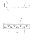
- Figure 1 shows a front view of an embodiment of the invention, in which the self-supporting U-shaped beam is illustrated;
- Figure 2 shows a side view of the embodiment of Figure 1;
- Figure 3 shows detail E of the embodiment of Figure 1;
- Figure 4 shows a three-dimensional view of the embodiment of Figure 1;
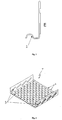
- Figure 5 shows a front view of the punched and profiled L-
shaped element 4; - Figure 6 shows a lateral view of the element of Figure 5;
- Figure 7 shows detail B of Figure 5;
- Figure 8 shows a three-dimensional view of the element of Figure 5;
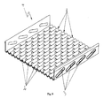
- Figure 9 shows a three-dimensional view of the interlocking of the ribs of the two angle irons.
- In Figure 1 a beam T is illustrated which consists of a punched and profiled element having a U shape 1, made of metal, preferably stainless steel, with
ribs 2 which are suitable for stiffening the element so that it can better withstand loads, mainly by bending, and also vertical gravitational forces. Theribs 2 are both on the base of the punched and profiled element and on its sides. The said element serves as a prefabricated structural load-bearing beam for the tops of the holes of openings, such as doors dividing inner rooms and windows. The said U-shaped punched and profiled element 1 is manufactured so as to comply with the different standard thicknesses and widths of doorways. Itscharacteristic ribbing 2 and punching is predetermined and it is dimensioned so that its capacity load is suitable for its use and also so that there is a good key for the plaster both inside and outside the section bar, i.e. the said U-shaped punched and profiled element. - When one section bar is laid on another section bar, i.e. in a continuous manner, the beam can be used as a prefabricated load-bearing reinforcement for small lofts.
- Figure 6 shows a second embodiment, which is a punched and profiled element having an L-
shaped profile 4, made of metal, withribs 2 both on its base and on its side. The said punched and profiled element having an L-shaped profile 4 is used in pairs, by joining two angle sections so that the particular ribbing on the base interlocks with the other, thereby creating a single U-shaped element. - As a result of this particular intersection of the section bars, by interlocking, it is possible to adjust the thickness to the thickness of the wall to be supported, since the plurality of ribs provides a wide range of possible connections between the two section bars.
- The feature of having two
angle sections 4, as shown in Figure 9, is that, when joined together, the said section bars form a single channel section, thereby making it possible to use two different metals, for example it is possible to use a stainless metal when manufacturing the section bar which will be used on the outward side, whereas the joined element is made of a different type of metal used on the inward side. - When one section bar is laid on another section bar, i.e. in a continuous manner, the beam can be used as a prefabricated load-bearing reinforcement for small lofts.
Claims (4)
- Self-supporting beam (T) for doors and windows, comprising at least one punched and profiled metal element (1), characterized in that the punched and profiled metal element is provided with a plurality of ribs (2) which are suitable for stiffening the beam, in which through holes (3) are formed in the said punched and profiled metal element (1) for a key for the plaster, the punched and profiled element (1) additionally having a U-shaped profile.
- Self-supporting beam (T) according to Claim 1, characterized in that the said metal element having a U-shaped profile comprises at least two punched and profiled metal elements (4), in which each punched and profiled metal element (4) has an L-shaped profile and is provided with a plurality of U-shaped ribs (2).
- Self-supporting beam (T) according to Claim 2, in which at least two punched and profiled metal elements (4) having an L-shaped profile are joined together by the interlocking of the said ribs (2) on each punched and profiled metal element (4) having an L-shaped profile.
- Use of a self-supporting beam (T) according to one of the preceding claims in a mixed steel-and-concrete reinforcement.
Applications Claiming Priority (1)
| Application Number | Priority Date | Filing Date | Title |
|---|---|---|---|
| CH12552006A CH700355B1 (en) | 2006-08-04 | 2006-08-04 | metal beam for doors and windows. |
Publications (1)
| Publication Number | Publication Date |
|---|---|
| EP1884604A2 true EP1884604A2 (en) | 2008-02-06 |
Family
ID=38603376
Family Applications (1)
| Application Number | Title | Priority Date | Filing Date |
|---|---|---|---|
| EP20070014831 Withdrawn EP1884604A2 (en) | 2006-08-04 | 2007-07-27 | Self-supporting metal beam for doors and windows |
Country Status (2)
| Country | Link |
|---|---|
| EP (1) | EP1884604A2 (en) |
| CH (1) | CH700355B1 (en) |
-
2006
- 2006-08-04 CH CH12552006A patent/CH700355B1/en not_active IP Right Cessation
-
2007
- 2007-07-27 EP EP20070014831 patent/EP1884604A2/en not_active Withdrawn
Also Published As
| Publication number | Publication date |
|---|---|
| CH700355B1 (en) | 2010-08-13 |
Similar Documents
| Publication | Publication Date | Title |
|---|---|---|
| US7784235B2 (en) | Load bearing construction element, in particular for manufacturing building floors, and floor structure incorporating such element | |
| US8646239B2 (en) | Modular building block building system | |
| EP2715004B1 (en) | Stronger wall system | |
| WO2011137496A9 (en) | A building structure | |
| US20100170194A1 (en) | Girders for reinforcing concrete and method for connecting them to pillars in order to provide continuity from bay to bay | |
| US20040216415A1 (en) | Welded wire reinforcement for modular concrete forms | |
| EP3115523A1 (en) | Concrete panel, especially for composite floors, and a composite floor | |
| EP3235967A1 (en) | Reinforced concrete slab, especially a floor slab and a floor system | |
| MXPA04010309A (en) | Cold rolled post for a security fence. | |
| WO2016161478A1 (en) | Stay-in-place beam formwork for concrete structures | |
| KR101614722B1 (en) | The flat and Ribbed slab | |
| CA2492969C (en) | Welded wire reinforcement for modular concrete forms | |
| GB2365456A (en) | Construction panel | |
| EP1884604A2 (en) | Self-supporting metal beam for doors and windows | |
| CN111356810B (en) | Balcony installation | |
| JP7264690B2 (en) | METHOD FOR MANUFACTURING CONCRETE WALL STRUCTURE AND BUILDING STRUCTURE | |
| GB2270535A (en) | Methods of reinforcing walls | |
| RU178522U1 (en) | Precast monolithic overlap | |
| AU2009200214A1 (en) | Composite Beam | |
| EP1327732A1 (en) | Edge shuttering for concrete slabs | |
| HU223213B1 (en) | Grilled lightweight concrete masonry ceiling | |
| AU2021102058A4 (en) | A beam for forming a slab with a settable material and a system of forming a slab of a building with a settable material | |
| EP2397619A1 (en) | System of self supporting masonry walls and building procedure | |
| EP2639372B1 (en) | Wall structure and method for manufacturing a wall structure | |
| AU2008100775A4 (en) | Method of building construction |
Legal Events
| Date | Code | Title | Description |
|---|---|---|---|
| PUAI | Public reference made under article 153(3) epc to a published international application that has entered the european phase |
Free format text: ORIGINAL CODE: 0009012 |
|
| AK | Designated contracting states |
Kind code of ref document: A2 Designated state(s): AT BE BG CH CY CZ DE DK EE ES FI FR GB GR HU IE IS IT LI LT LU LV MC MT NL PL PT RO SE SI SK TR |
|
| AX | Request for extension of the european patent |
Extension state: AL BA HR MK YU |
|
| STAA | Information on the status of an ep patent application or granted ep patent |
Free format text: STATUS: THE APPLICATION IS DEEMED TO BE WITHDRAWN |
|
| 18D | Application deemed to be withdrawn |
Effective date: 20120201 |