EP0434869B1 - Steel stud and precast panel - Google Patents
Steel stud and precast panel Download PDFInfo
- Publication number
- EP0434869B1 EP0434869B1 EP89313582A EP89313582A EP0434869B1 EP 0434869 B1 EP0434869 B1 EP 0434869B1 EP 89313582 A EP89313582 A EP 89313582A EP 89313582 A EP89313582 A EP 89313582A EP 0434869 B1 EP0434869 B1 EP 0434869B1
- Authority
- EP
- European Patent Office
- Prior art keywords
- slab
- openings
- stud member
- junction flange
- locking strip
- Prior art date
- Legal status (The legal status is an assumption and is not a legal conclusion. Google has not performed a legal analysis and makes no representation as to the accuracy of the status listed.)
- Expired - Lifetime
Links
- 229910000831 Steel Inorganic materials 0.000 title claims description 20
- 239000010959 steel Substances 0.000 title claims description 20
- 239000000463 material Substances 0.000 claims description 16
- 230000003014 reinforcing effect Effects 0.000 claims description 15
- 238000010276 construction Methods 0.000 claims description 14
- 239000002184 metal Substances 0.000 claims description 9
- 230000001154 acute effect Effects 0.000 claims description 5
- 230000002787 reinforcement Effects 0.000 description 6
- 229910001294 Reinforcing steel Inorganic materials 0.000 description 4
- 239000002131 composite material Substances 0.000 description 4
- 230000015572 biosynthetic process Effects 0.000 description 3
- 230000005494 condensation Effects 0.000 description 3
- 238000009833 condensation Methods 0.000 description 3
- 238000005755 formation reaction Methods 0.000 description 3
- 238000004519 manufacturing process Methods 0.000 description 3
- 238000000034 method Methods 0.000 description 3
- 238000009413 insulation Methods 0.000 description 2
- 230000000284 resting effect Effects 0.000 description 2
- 229910000746 Structural steel Inorganic materials 0.000 description 1
- 230000004888 barrier function Effects 0.000 description 1
- 238000005266 casting Methods 0.000 description 1
- 239000004035 construction material Substances 0.000 description 1
- 238000011161 development Methods 0.000 description 1
- 230000018109 developmental process Effects 0.000 description 1
- 230000000694 effects Effects 0.000 description 1
- 239000004744 fabric Substances 0.000 description 1
- 238000009408 flooring Methods 0.000 description 1
- 229910052602 gypsum Inorganic materials 0.000 description 1
- 239000010440 gypsum Substances 0.000 description 1
- 238000010438 heat treatment Methods 0.000 description 1
- 238000009434 installation Methods 0.000 description 1
- 238000003466 welding Methods 0.000 description 1
Images


Classifications
-
- E—FIXED CONSTRUCTIONS
- E04—BUILDING
- E04C—STRUCTURAL ELEMENTS; BUILDING MATERIALS
- E04C3/00—Structural elongated elements designed for load-supporting
- E04C3/30—Columns; Pillars; Struts
- E04C3/32—Columns; Pillars; Struts of metal
-
- E—FIXED CONSTRUCTIONS
- E04—BUILDING
- E04B—GENERAL BUILDING CONSTRUCTIONS; WALLS, e.g. PARTITIONS; ROOFS; FLOORS; CEILINGS; INSULATION OR OTHER PROTECTION OF BUILDINGS
- E04B5/00—Floors; Floor construction with regard to insulation; Connections specially adapted therefor
- E04B5/02—Load-carrying floor structures formed substantially of prefabricated units
- E04B5/04—Load-carrying floor structures formed substantially of prefabricated units with beams or slabs of concrete or other stone-like material, e.g. asbestos cement
-
- E—FIXED CONSTRUCTIONS
- E04—BUILDING
- E04B—GENERAL BUILDING CONSTRUCTIONS; WALLS, e.g. PARTITIONS; ROOFS; FLOORS; CEILINGS; INSULATION OR OTHER PROTECTION OF BUILDINGS
- E04B5/00—Floors; Floor construction with regard to insulation; Connections specially adapted therefor
- E04B5/16—Load-carrying floor structures wholly or partly cast or similarly formed in situ
- E04B5/17—Floor structures partly formed in situ
- E04B5/23—Floor structures partly formed in situ with stiffening ribs or other beam-like formations wholly or partly prefabricated
- E04B5/29—Floor structures partly formed in situ with stiffening ribs or other beam-like formations wholly or partly prefabricated the prefabricated parts of the beams consisting wholly of metal
-
- E—FIXED CONSTRUCTIONS
- E04—BUILDING
- E04C—STRUCTURAL ELEMENTS; BUILDING MATERIALS
- E04C2/00—Building elements of relatively thin form for the construction of parts of buildings, e.g. sheet materials, slabs, or panels
- E04C2/02—Building elements of relatively thin form for the construction of parts of buildings, e.g. sheet materials, slabs, or panels characterised by specified materials
- E04C2/26—Building elements of relatively thin form for the construction of parts of buildings, e.g. sheet materials, slabs, or panels characterised by specified materials composed of materials covered by two or more of groups E04C2/04, E04C2/08, E04C2/10 or of materials covered by one of these groups with a material not specified in one of the groups
- E04C2/284—Building elements of relatively thin form for the construction of parts of buildings, e.g. sheet materials, slabs, or panels characterised by specified materials composed of materials covered by two or more of groups E04C2/04, E04C2/08, E04C2/10 or of materials covered by one of these groups with a material not specified in one of the groups at least one of the materials being insulating
- E04C2/288—Building elements of relatively thin form for the construction of parts of buildings, e.g. sheet materials, slabs, or panels characterised by specified materials composed of materials covered by two or more of groups E04C2/04, E04C2/08, E04C2/10 or of materials covered by one of these groups with a material not specified in one of the groups at least one of the materials being insulating composed of insulating material and concrete, stone or stone-like material
-
- E—FIXED CONSTRUCTIONS
- E04—BUILDING
- E04C—STRUCTURAL ELEMENTS; BUILDING MATERIALS
- E04C2/00—Building elements of relatively thin form for the construction of parts of buildings, e.g. sheet materials, slabs, or panels
- E04C2/30—Building elements of relatively thin form for the construction of parts of buildings, e.g. sheet materials, slabs, or panels characterised by the shape or structure
- E04C2/38—Building elements of relatively thin form for the construction of parts of buildings, e.g. sheet materials, slabs, or panels characterised by the shape or structure with attached ribs, flanges, or the like, e.g. framed panels
- E04C2/384—Building elements of relatively thin form for the construction of parts of buildings, e.g. sheet materials, slabs, or panels characterised by the shape or structure with attached ribs, flanges, or the like, e.g. framed panels with a metal frame
-
- E—FIXED CONSTRUCTIONS
- E04—BUILDING
- E04C—STRUCTURAL ELEMENTS; BUILDING MATERIALS
- E04C3/00—Structural elongated elements designed for load-supporting
- E04C3/02—Joists; Girders, trusses, or trusslike structures, e.g. prefabricated; Lintels; Transoms; Braces
- E04C3/04—Joists; Girders, trusses, or trusslike structures, e.g. prefabricated; Lintels; Transoms; Braces of metal
- E04C3/08—Joists; Girders, trusses, or trusslike structures, e.g. prefabricated; Lintels; Transoms; Braces of metal with apertured web, e.g. with a web consisting of bar-like components; Honeycomb girders
- E04C3/09—Joists; Girders, trusses, or trusslike structures, e.g. prefabricated; Lintels; Transoms; Braces of metal with apertured web, e.g. with a web consisting of bar-like components; Honeycomb girders at least partly of bent or otherwise deformed strip- or sheet-like material
-
- E—FIXED CONSTRUCTIONS
- E04—BUILDING
- E04C—STRUCTURAL ELEMENTS; BUILDING MATERIALS
- E04C3/00—Structural elongated elements designed for load-supporting
- E04C3/02—Joists; Girders, trusses, or trusslike structures, e.g. prefabricated; Lintels; Transoms; Braces
- E04C3/04—Joists; Girders, trusses, or trusslike structures, e.g. prefabricated; Lintels; Transoms; Braces of metal
- E04C2003/0404—Joists; Girders, trusses, or trusslike structures, e.g. prefabricated; Lintels; Transoms; Braces of metal beams, girders, or joists characterised by cross-sectional aspects
- E04C2003/0408—Joists; Girders, trusses, or trusslike structures, e.g. prefabricated; Lintels; Transoms; Braces of metal beams, girders, or joists characterised by cross-sectional aspects characterised by assembly or the cross-section
- E04C2003/0421—Joists; Girders, trusses, or trusslike structures, e.g. prefabricated; Lintels; Transoms; Braces of metal beams, girders, or joists characterised by cross-sectional aspects characterised by assembly or the cross-section comprising one single unitary part
-
- E—FIXED CONSTRUCTIONS
- E04—BUILDING
- E04C—STRUCTURAL ELEMENTS; BUILDING MATERIALS
- E04C3/00—Structural elongated elements designed for load-supporting
- E04C3/02—Joists; Girders, trusses, or trusslike structures, e.g. prefabricated; Lintels; Transoms; Braces
- E04C3/04—Joists; Girders, trusses, or trusslike structures, e.g. prefabricated; Lintels; Transoms; Braces of metal
- E04C2003/0404—Joists; Girders, trusses, or trusslike structures, e.g. prefabricated; Lintels; Transoms; Braces of metal beams, girders, or joists characterised by cross-sectional aspects
- E04C2003/0426—Joists; Girders, trusses, or trusslike structures, e.g. prefabricated; Lintels; Transoms; Braces of metal beams, girders, or joists characterised by cross-sectional aspects characterised by material distribution in cross section
- E04C2003/0434—Joists; Girders, trusses, or trusslike structures, e.g. prefabricated; Lintels; Transoms; Braces of metal beams, girders, or joists characterised by cross-sectional aspects characterised by material distribution in cross section the open cross-section free of enclosed cavities
-
- E—FIXED CONSTRUCTIONS
- E04—BUILDING
- E04C—STRUCTURAL ELEMENTS; BUILDING MATERIALS
- E04C3/00—Structural elongated elements designed for load-supporting
- E04C3/02—Joists; Girders, trusses, or trusslike structures, e.g. prefabricated; Lintels; Transoms; Braces
- E04C3/04—Joists; Girders, trusses, or trusslike structures, e.g. prefabricated; Lintels; Transoms; Braces of metal
- E04C2003/0404—Joists; Girders, trusses, or trusslike structures, e.g. prefabricated; Lintels; Transoms; Braces of metal beams, girders, or joists characterised by cross-sectional aspects
- E04C2003/0443—Joists; Girders, trusses, or trusslike structures, e.g. prefabricated; Lintels; Transoms; Braces of metal beams, girders, or joists characterised by cross-sectional aspects characterised by substantial shape of the cross-section
- E04C2003/0473—U- or C-shaped
Definitions
- the invention relates to a thermally efficient steel stud having an edge flange with openings for embedment in concrete, and to a composite precast panel incorporating such steel studs.
- Precast panels typically being finished on one side, offer numerous advantages in construction. In the majority of cases the cost of the building will be reduced, where precast panels are used. In addition, it is possible to design an exterior formation on the panel having an attractive appearance. In many cases the panel material is concrete, incorporating reinforcement. Typically the thickness of the concrete panelling will be between about one and two inches. Panels of this thickness require some form of structural reinforcement to provide rigidity. In addition, where such panels are used for exterior load-bearing walls, then they must incorporate some form of structural members.
- Such panels will be erected in place to provide a finished exterior, and the interior of the panels will then be covered in and finished at a later stage.
- the interior of the panels may be refinished in the factory and insulation may also be installed so that a complete wall system is achieved prior to installation.
- precast panels are in providing exterior wall systems for commercial and industrial buildings and high rise office buildings and apartments and the like, and also interior wall systems, if desired, with a variety of finishes.
- the thickness of the precast panel shall be reduced to a minimum compatible with achieving these objectives.
- Such a thin-wall panel system is shown, for example, in U.S. Patent 4,602,467,HK Schilger, Granted July 29, 1986.
- the exterior of the panel presents a finished appearance, and the interior of the panel has a plurality of metal studs or channels partially embedded in its surface.
- precast panels of very considerable size, and of a thickness of between one and two inches.
- Reinforcing steel is incorporated in the panels, and the structural steel studs have portions which are embedded in the concrete on one side of reinforcing steel web.
- the steel stud used for this purpose has often been of a simple C-shaped channel, with one edge of the channel simply resting against the reinforcing steel mesh.
- the weight of the metal studs themselves is also a significant factor in the overall weight of the panels. Any reduction in weight that can be achieved, without loss in rigidity, will produce significant benefits.
- U.S. Patent 3,217,460, Downing, Granted November 16, 1965 discloses a steel stud for supporting panels of drywall.
- the stud had an edge flange with interlock formations on each side of the stud. This enabled the edge flange to engage and support the edges of two adjacent drywall panels.
- This system was not suitable for use in cast concrete. This system, if used with cast concrete, in thin wall panels, i.e. panels of about one and one half inches in thickness, would create a line of weakness in the panel, and could cause failure.
- the studs themselves would have great thermal conductivity, causing cold spots or "ghosting", on the inside of the drywall, from condensation of moisture.
- thermoly efficient steel stud having an edge flange with openings for embedment in concrete, and to a precast panel with such steel studs which is designed so that the weight of the steel stud is reduced to a minimum, and having its own integral securing means for securing the stud to the precast slab and which incorporates openings along its length which effectively reduces heat transfer through the stud, and which avoids lines of weakness in the slab.
- the invention comprises a thermally efficient stud member according to claim 1, being a one piece integral sheet metal structure comprising two parallel spaced-apart structural members extending parallel to one another; a plurality of spaced-apart strut members extending integrally between said structural members, said strut members having a generally channel shaped cross section and having openings therebetween; a junction flange integrally formed with and extending angularly from one of said structural members and embedded in said slab and having openings therethrough; and a locking strip integrally formed with said junction flange, disposed at a non-perpendicular angle relative thereto.
- the invention also comprises a precast thin wall construction panel according to claim 8.
- a composite precast panel having a concrete slab and a plurality of such studs with their junction flanges and locking strips embedded in said slab, said locking strip being disposed within said slab at an acute angle thereto and extending to one side only of said junction flange, and said cast concrete material extending through said openings in said junction flange.
- a precast panel generally indicated at 10 comprises a slab 12 having a first surface 13 and typically formed of concrete, with a steel reinforcing mesh R ( Figure 3) embedded therein.
- a plurality of steel stud members generally indicated at 14 are attached on one side of the slab portion 12 and in a manner to be described below.
- the stud member 14 comprises inner and outer generally L-shaped angle portions generally indicated at 20 and 22 respectively.
- Each of the angle portions 20 and 22 comprises respective flanges 24 and 26, and bracing flanges 28 and 30.
- the flange 24 is usefully formed with a reinforcing edge flange 25.
- Respective ones of the flanges 24, 26 and the bracing flanges 28, 30 form a right angle, so that the two flanges 24 and 26 are disposed in mutually parallel spaced-apart planes.
- angled struts 32 extend integrally between them. Struts 32 are usefully formed into a generally three-sided channel shape by means of turning down the edge flange portion 34 on one or both sides.
- Angle portions 20 and 22 and struts 32 are all formed integrally out of a single piece of sheet metal. Typically they will be formed by roll forming techniques, with openings being blanked out between the struts 32.
- openings are shown generally as 36. Studs of this type are considerably lighter than equivalent studs of conventional C-shape cross section. In addition, the forming of openings in the studs between the edges thereof both reduces the heat transfer through the stud, and at the same time provides adequate openings for passing services through the studs. If desired, the edges of the bracing flanges 28 and 30 can also be turned down so that the openings 36 are peripherally defined on all sides by integrally formed flanges.
- junction flange 40 extends from flange 26, at right angles thereto, and a locking strip 42 extends from junction flange 40 for securing the flange 40 in the concrete panel.
- the locking strip 42 is, in accordance with an important feature of this invention, disposed at an acute angle to the first surface 13 of the slab 12.
- Openings 44 are struck out of junction flange 40 as shown in Figure 2, at intervals, to allow concrete to flow through during manufacture of the panel 10.
- the openings 44 can be formed so as to extend into the locking strip 42 as will be more readily understood as alternative embodiments of such studs are hereinafter described.
- the stud members 14 are assembled together and fastened into a framework, similar to the framework used when erecting studding for a wall. That is to say, a plurality of the studs are arranged in mutually parallel spaced-apart locations typically on sixteen or twenty-four inch centers for example, and top and bottom struts may be attached at either end, if required.
- the manufacture of the composite panel 10 then proceeds by pouring a sufficient depth of the precast material, typically concrete, into a horizontal mould. In a typical example it will be poured to a depth of about one and a half inches, the actual thickness depending upon various factors and design considerations.
- a sufficient depth of the precast material typically concrete
- the reinforcing mesh R is then placed on the surface of the concrete.
- the locking strip 42 and the junction flange 40 will be immersed in the concrete, and the flange 26 will typically be resting on the first surface 13 of the concrete.
- the rectangular framework of studs may then be secured, if desired, so that it cannot sink any further, until the panel is set and cured.
- the reinforcing mesh can be attached by simply looping wires (not shown) through the reinforcing mesh and through the openings 44, and tying them off at various intervals.
- Panels made in this way are found to exhibit great strength and durability.
- the studs are consequently securely fastened to the slab, enabling the panels to be moved, installed and fastened.
- the low thermal conductivity of the studs substantially eliminates cold spots and condensation on interior wall surfaces which, in the past, occurred with conventional metal studs.
- the discontinuous junction flange 40 is greatly superior to a flange which is continuous and uninterrupted.
- a continuous junction flange would form a continuous barrier or line of weakness in the slab, to a depth of one half to three quarters of an inch. This is not desirable and may make the panel more fragile.
- the material of the slab flows around the locking strip 42 and through the openings 44 in the junction flange 40.
- the slab will thus effectively maintain its integrity at least in the region of openings 44, and in this way the slab will be stronger, and it may be possible to use a thinner slab.
- panels according to the invention are desirable to use as flooring, or roofing.
- any or all of the studs may be modified by the provision of a triangular reinforcement tube 50 outwardly of the first surface 13 of the slab 12.
- Tube 50 is provided instead of the inner angle portion 20 shown in Figure 3.
- Tube 50 comprises side walls 52 and 54 and bottom wall 56 formed integrally into a triangular shape in section. Reinforcing ribs may be formed, if desired, at spaced intervals in side walls 52 and 54 for greater strength.
- Side walls 52 and 54 are fastened together by any suitable means such as spot welding, riveting, or integral swaging at 58.
- the tubular construction of reinforcement 50 adds increased stress resistance to the strut. By its location in a plane spaced apart from the slab, it is placed in tension and reduces flexing of the slab.
- the triangular shape of reinforcement can be replaced by a generally closed T-shaped formation (not shown) if desired. It is believed that its construction is self-evident and requires no further description.
- the slabs resulting from the use of this structure will be considerably stronger, and can carry considerably heavier loads, than is possible using a continuous junction flange.
- the provision of openings in the junction flange 40 also assists in reducing problems created by differences in the rate of thermal expansion as between the material of the studs themselves, and the slab.
- the locking strip 42 can be made somewhat narrower than if those openings 44 extend into the locking strip 42.
- the panels 10 are usually attached to form the exterior wall of a building although they can be used as interior walls, if desired. Insulation can be placed between the studs, and interior wall panelling, such as gypsum wallboard can be attached the mounting flanges on the interior of the studs.
- interior wall panelling such as gypsum wallboard
- FIG. 60 there is indicated generally at 60 an alternate embodiment of a steel stud member for use in a precast panel in accordance with the invention.
- the stud member 60 is similar to the stud member 14 already described in that it comprises an inner angle portion 62 and an outer angle portion 64, the former being provided with a reinforcing edge flange 65.
- Struts 66 extend between bracing flanges 67 and 68 and define openings 69 therebetween.
- the outer angle portion 62 comprises a mounting flange 70 which is integrally formed with a junction flange 72 which extends therefrom at an acute angle and which is in turn integrally formed with a locking strip 74. Openings 76 are formed in the junction flange 72 and such openings 76 usefully extend partly into the locking strip 74 as actually shown.
- Figure 6 in which there is shown generally at 80 yet another embodiment of a stud member for use in a panel in accordance with this invention. Identical components of the stud members 60 and 80 are identified by the same legends to avoid undue duplication of the description herein.
- the stud member 80 differs from the stud member 60 in that it is not provided with a mounting flange 70 but instead with a junction flange 82 which is integrally formed with the bracing flange 68 and which extends angularly therefrom.
- a locking strip 84 is integrally formed with the junction flange 82 and extends angularly therefrom so as to be disposed at an acute angle to the surface of the slab (not shown).
Landscapes
- Engineering & Computer Science (AREA)
- Architecture (AREA)
- Civil Engineering (AREA)
- Structural Engineering (AREA)
- Physics & Mathematics (AREA)
- Electromagnetism (AREA)
- Load-Bearing And Curtain Walls (AREA)
- Panels For Use In Building Construction (AREA)
- Joining Of Building Structures In Genera (AREA)
- Mutual Connection Of Rods And Tubes (AREA)
- Revetment (AREA)
Description
- The invention relates to a thermally efficient steel stud having an edge flange with openings for embedment in concrete, and to a composite precast panel incorporating such steel studs.
- Precast panels, typically being finished on one side, offer numerous advantages in construction. In the majority of cases the cost of the building will be reduced, where precast panels are used. In addition, it is possible to design an exterior formation on the panel having an attractive appearance. In many cases the panel material is concrete, incorporating reinforcement. Typically the thickness of the concrete panelling will be between about one and two inches. Panels of this thickness require some form of structural reinforcement to provide rigidity. In addition, where such panels are used for exterior load-bearing walls, then they must incorporate some form of structural members.
- Typically, such panels will be erected in place to provide a finished exterior, and the interior of the panels will then be covered in and finished at a later stage.
- In other applications, the interior of the panels may be refinished in the factory and insulation may also be installed so that a complete wall system is achieved prior to installation.
- Applications for such precast panels are in providing exterior wall systems for commercial and industrial buildings and high rise office buildings and apartments and the like, and also interior wall systems, if desired, with a variety of finishes.
- In the majority of cases, such panelling systems are supported on the building structure, and do not normally provide any load bearing capacity, other than resistance to wind loads.
- In these cases, the panels must be securely attached to the fabric of building.
- The design of such precast panels must, however, be such that it meets all of the foregoing objectives in a satisfactory and efficient manner, and also at a reasonable cost. In most construction projects the actual weight of the material used in construction is of great importance. The weight of the materials affects both the cost of the materials and also the cost of shipping, and imposes limits on the manner in which the materials can be handled at the construction site.
- In addition to all of these limitations, however, especially in the construction of high rise buildings, the weight of the construction materials is a critical factor in the design of the entire building.
- Where a significant reduction in material weight can be achieved, then it becomes possible to optimize the design of the entire building and reduce construction costs. For all these reasons, therefore, it is desirable that the thickness of the precast panel shall be reduced to a minimum compatible with achieving these objectives.
- Accordingly, developments in the design of such precast panelling have been along the lines of reducing the thickness of the panel, and incorporating metal structural studs or channels on the one side of the panel.
- Such a thin-wall panel system is shown, for example, in U.S. Patent 4,602,467,HK Schilger, Granted July 29, 1986.
- Using a combination panel re-inforced with steel studs, the exterior of the panel presents a finished appearance, and the interior of the panel has a plurality of metal studs or channels partially embedded in its surface.
- Using these techniques, it has been found possible to construct precast panels of very considerable size, and of a thickness of between one and two inches.
- Reinforcing steel is incorporated in the panels, and the structural steel studs have portions which are embedded in the concrete on one side of reinforcing steel web.
- In the past, the steel stud used for this purpose has often been of a simple C-shaped channel, with one edge of the channel simply resting against the reinforcing steel mesh.
- This however, is not always a satisfactory method of attachment. The edge of the channel creates a line of weakness in the panel.
- In addition the use of a simple C-shaped channel creates obstructions in the wall. If any electrical services are to be run through the wall, then the openings must be made through the channels.
- Another significant problem has been heat transfer through the channels when the panels are used on the exterior of a building. The metal causes patches of cold on the interior walls of the building, resulting in condensation in and on the wall known as "ghosting". The heating load in the building is also increased.
- The weight of the metal studs themselves is also a significant factor in the overall weight of the panels. Any reduction in weight that can be achieved, without loss in rigidity, will produce significant benefits.
- In some cases it may be desirable to use such panels as floors or roofing, but in the past the studs have been inadequate to support the load.
- U.S. Patent 3,217,460, Downing, Granted November 16, 1965, discloses a steel stud for supporting panels of drywall. The stud had an edge flange with interlock formations on each side of the stud. This enabled the edge flange to engage and support the edges of two adjacent drywall panels. This system was not suitable for use in cast concrete. This system, if used with cast concrete, in thin wall panels, i.e. panels of about one and one half inches in thickness, would create a line of weakness in the panel, and could cause failure. In addition, the studs themselves would have great thermal conductivity, causing cold spots or "ghosting", on the inside of the drywall, from condensation of moisture.
- For all of these reasons therefore it is desirable to provide a thermally efficient steel stud having an edge flange with openings for embedment in concrete, and to a precast panel with such steel studs which is designed so that the weight of the steel stud is reduced to a minimum, and having its own integral securing means for securing the stud to the precast slab and which incorporates openings along its length which effectively reduces heat transfer through the stud, and which avoids lines of weakness in the slab.
- With a view to achieving the various objectives set out above, the invention comprises a thermally efficient stud member according to claim 1, being a one piece integral sheet metal structure comprising two parallel spaced-apart structural members extending parallel to one another; a plurality of spaced-apart strut members extending integrally between said structural members, said strut members having a generally channel shaped cross section and having openings therebetween; a junction flange integrally formed with and extending angularly from one of said structural members and embedded in said slab and having openings therethrough; and a locking strip integrally formed with said junction flange, disposed at a non-perpendicular angle relative thereto. The invention also comprises a precast thin wall construction panel according to claim 8.
- More particularly it is an objective of the invention to provide a composite precast panel having a concrete slab and a plurality of such studs with their junction flanges and locking strips embedded in said slab, said locking strip being disposed within said slab at an acute angle thereto and extending to one side only of said junction flange, and said cast concrete material extending through said openings in said junction flange.
- More particularly, it is an objective of the invention to provide a precast panel having stud members of the type described having additional reinforcement means on the angle member remote from said junction strip.
- It is a further and related objective of the invention to provide a precast panel incorporating a plurality of stud members located in predetermined parallel spaced-apart relationship, extending from one edge to the other of said panel, and including upper and lower frame members extending between the upper and lower ends of said stud members, and panel material cast around said locking strips.
- The various features of novelty which characterize the invention are pointed out with particularity in the claims annexed to and forming a part of this disclosure. For a better understanding of the invention, its operating advantages and specific objects attained by its use, reference should be had to the accompanying drawings and descriptive matter in which there are illustrated and described preferred embodiments of the invention.
- The various features of novelty which characterize the invention are pointed out with more particularity in the claims annexed to and forming a part of this disclosure. For a better understanding of the invention, its operating advantages and specific objects attained by its use, reference should be had to the accompanying drawings and descriptive matter in which there are illustrated and described preferred emobdiments of the invention.
- The invention will now be described merely by way of illustration with reference to the accompanying drawings in which:
- Figure 1 is a perspective view of a typical precast panel according to the invention;
- Figure 2 is a fragmentary perspective view of one embodiment of a stud member used in a panel according to the invention;
- Figure 3 is a fragmentary section through a typical panel incorporating the stud member shown in Figure 2;
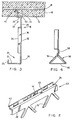
- Figure 4 is a partial section showing a useful feature for a stud member used in the invention;
- Figure 5 is a fragmentary perspective view of an alternative embodiment of a stud member used in the invention; and
- Figure 6 is a fragmentary perspective view of yet another embodiment of a stud member used in the invention.
- As shown in Figure 1, a precast panel generally indicated at 10 comprises a
slab 12 having afirst surface 13 and typically formed of concrete, with a steel reinforcing mesh R (Figure 3) embedded therein. A plurality of steel stud members generally indicated at 14 are attached on one side of theslab portion 12 and in a manner to be described below. - As best shown in Figures 2 and 3, the
stud member 14 comprises inner and outer generally L-shaped angle portions generally indicated at 20 and 22 respectively. Each of theangle portions respective flanges bracing flanges flange 24 is usefully formed with a reinforcing edge flange 25. - Respective ones of the
flanges bracing flanges flanges - In order to join the two
angle portions angled struts 32 extend integrally between them.Struts 32 are usefully formed into a generally three-sided channel shape by means of turning down theedge flange portion 34 on one or both sides. -
Angle portions struts 32. - Such openings are shown generally as 36. Studs of this type are considerably lighter than equivalent studs of conventional C-shape cross section. In addition, the forming of openings in the studs between the edges thereof both reduces the heat transfer through the stud, and at the same time provides adequate openings for passing services through the studs. If desired, the edges of the bracing
flanges openings 36 are peripherally defined on all sides by integrally formed flanges. - In order to secure the studs in a precast panel a
junction flange 40 extends fromflange 26, at right angles thereto, and alocking strip 42 extends fromjunction flange 40 for securing theflange 40 in the concrete panel. As will best be understood by reference to Figure 3, the lockingstrip 42 is, in accordance with an important feature of this invention, disposed at an acute angle to thefirst surface 13 of theslab 12. -
Openings 44 are struck out ofjunction flange 40 as shown in Figure 2, at intervals, to allow concrete to flow through during manufacture of thepanel 10. Usefully, theopenings 44 can be formed so as to extend into the lockingstrip 42 as will be more readily understood as alternative embodiments of such studs are hereinafter described. - In the manufacture of the
composite precast panel 10, thestud members 14 are assembled together and fastened into a framework, similar to the framework used when erecting studding for a wall. That is to say, a plurality of the studs are arranged in mutually parallel spaced-apart locations typically on sixteen or twenty-four inch centers for example, and top and bottom struts may be attached at either end, if required. - The manufacture of the
composite panel 10 then proceeds by pouring a sufficient depth of the precast material, typically concrete, into a horizontal mould. In a typical example it will be poured to a depth of about one and a half inches, the actual thickness depending upon various factors and design considerations. - The reinforcing mesh R is then placed on the surface of the concrete.
- The entire rectangular framework of studs is then lowered down into the mould so as to rest on the reinforcing mesh and is then pressed downwardly part way into the concrete.
- When the desired depth has been reached, the locking
strip 42 and thejunction flange 40 will be immersed in the concrete, and theflange 26 will typically be resting on thefirst surface 13 of the concrete. - The rectangular framework of studs may then be secured, if desired, so that it cannot sink any further, until the panel is set and cured.
- Once cured, the entire panel is then freed from the mould.
- It has not been found necessary to provide any attachment between the stud members and the reinforcing steel mesh in the concrete. However, for the sake of convenience, if some form of attachment is desired, for example, to assist in the actual assembly and casting of the panels, then the reinforcing mesh can be attached by simply looping wires (not shown) through the reinforcing mesh and through the
openings 44, and tying them off at various intervals. - In most cases, however, it is simply a matter of first of all placing the reinforcing mesh on the poured concrete in the mould, and then lowering the framework consisting of studs down on to the reinforcing mesh, and continuing lowering the framework until it has entered the concrete to the desired depth.
- This will also have the effect of forcing the reinforcing mesh into the concrete to the desired depth. In practice it is found that the reinforcing mesh will not sink any further, but will remain in the correct position.
- Panels made in this way are found to exhibit great strength and durability. The studs are consequently securely fastened to the slab, enabling the panels to be moved, installed and fastened.
- The low thermal conductivity of the studs substantially eliminates cold spots and condensation on interior wall surfaces which, in the past, occurred with conventional metal studs.
- The
discontinuous junction flange 40 is greatly superior to a flange which is continuous and uninterrupted. Typically, in a slab of a thickness of one and one-half inches, a continuous junction flange would form a continuous barrier or line of weakness in the slab, to a depth of one half to three quarters of an inch. This is not desirable and may make the panel more fragile. - The material of the slab flows around the locking
strip 42 and through theopenings 44 in thejunction flange 40. - The slab will thus effectively maintain its integrity at least in the region of
openings 44, and in this way the slab will be stronger, and it may be possible to use a thinner slab. - In some cases, it is desirable to use panels according to the invention as flooring, or roofing.
- Depending upon the load to be carried, it may be desirable to increase the load-bearing capacity of the studs.
- In accordance with a further embodiment shown in Figure 4, any or all of the studs may be modified by the provision of a
triangular reinforcement tube 50 outwardly of thefirst surface 13 of theslab 12. -
Tube 50 is provided instead of theinner angle portion 20 shown in Figure 3. -
Tube 50 comprisesside walls 52 and 54 andbottom wall 56 formed integrally into a triangular shape in section. Reinforcing ribs may be formed, if desired, at spaced intervals inside walls 52 and 54 for greater strength. -
Side walls 52 and 54 are fastened together by any suitable means such as spot welding, riveting, or integral swaging at 58. - The tubular construction of
reinforcement 50 adds increased stress resistance to the strut. By its location in a plane spaced apart from the slab, it is placed in tension and reduces flexing of the slab. - The triangular shape of reinforcement can be replaced by a generally closed T-shaped formation (not shown) if desired. It is believed that its construction is self-evident and requires no further description.
- Since the material of the slab is free to flow through the
openings 44 in thejunction flanges 40, the slabs resulting from the use of this structure will be considerably stronger, and can carry considerably heavier loads, than is possible using a continuous junction flange. - In addition to these advantages, however, the provision of openings in the
junction flange 40 also assists in reducing problems created by differences in the rate of thermal expansion as between the material of the studs themselves, and the slab. - If the
openings 44 are formed in only thejunction flange 40, the lockingstrip 42 can be made somewhat narrower than if thoseopenings 44 extend into the lockingstrip 42. - In use, the
panels 10 are usually attached to form the exterior wall of a building although they can be used as interior walls, if desired. Insulation can be placed between the studs, and interior wall panelling, such as gypsum wallboard can be attached the mounting flanges on the interior of the studs. - Reference will next be made to Figure 5 in which there is indicated generally at 60 an alternate embodiment of a steel stud member for use in a precast panel in accordance with the invention. The
stud member 60 is similar to thestud member 14 already described in that it comprises aninner angle portion 62 and anouter angle portion 64, the former being provided with a reinforcingedge flange 65.Struts 66 extend between bracingflanges openings 69 therebetween. - The
outer angle portion 62 comprises a mountingflange 70 which is integrally formed with ajunction flange 72 which extends therefrom at an acute angle and which is in turn integrally formed with a lockingstrip 74.Openings 76 are formed in thejunction flange 72 andsuch openings 76 usefully extend partly into the lockingstrip 74 as actually shown. Reference will now be made to Figure 6 in which there is shown generally at 80 yet another embodiment of a stud member for use in a panel in accordance with this invention. Identical components of thestud members - The
stud member 80 differs from thestud member 60 in that it is not provided with a mountingflange 70 but instead with ajunction flange 82 which is integrally formed with the bracingflange 68 and which extends angularly therefrom. In turn, a lockingstrip 84 is integrally formed with thejunction flange 82 and extends angularly therefrom so as to be disposed at an acute angle to the surface of the slab (not shown). - The foregoing is a description of a preferred embodiment of the invention which is given here by way of example only. The invention is not to be taken as limited to any of the specific features as described, but comprehends all such variations thereof as come within the scope of the appended claims.
Claims (12)
- A steel stud member (14,60,80) adapted to be partially embedded in a slab of cast concrete material, said slab defining inner and outer surfaces, and said stud member being
a one piece integral sheet metal structure, comprising
two parallel spaced-apart structural members 20,22,67,68) extending parallel to one another;
characterized in that said stud member further comprises;
a plurality of spaced-apart strut members (32,66) extending integrally between said structural members, said strut members having a generally channel shaped cross section, and having openings (36,69) therebetween;
a junction flange (40,72,82) integrally formed with and extending angularly from one of said structural members (20,22,67,68) and having openings (44,76,86) therethrough; and
a locking strip (42,74,84) integrally formed with said junction flange (40,72,82), disposed at a non-perpendicular angle relative thereto,
said locking strip and said junction flange being adapted to be embedded within a said slab, and whereby said cast concrete material may be permitted to extend through said openings (44,76,86) in said junction flange (40,72,82). - A steel stud member as claimed in Claim 1 and wherein said openings (36,69) in said junction flange (40,72,82) extend partly into said locking strip (42,74,84).
- A steel stud member as claimed in Claim 1 and which additionally comprises a reinforcing tube (50) integrally formed therewith at a position spaced apart from said junction flange (40), such that said reinforcing tube and said junction flange are separated by said strut members.
- A steel stud member as claimed in Claim 1 and in which said locking strip (42) is oriented at an acute angle to said junction flange (40).
- A steel stud member as claimed in Claim 1 and in which said openings (36,69) between said strut members (32,66) are peripherally defined at least in part by flanges (34) integrally formed with said strut members.
- A steel stud member as claimed in Claim 1 wherein said junction flange (72,82) is oriented at a non-perpendicular angle relative to said stud member.
- A steel stud member as claimed in Claim 6 wherein said locking strip (74,84) is oriented at a non-perpendicular angle relative to said junction flange (72,82).
- A precast thin wall construction panel (10) having low thermal conductivity and comprising a slab (12) of cast concrete material having a first surface, and a plurality of parallel spaced apart steel stud members (14) partially embedded in, and extending from said first surface of said slab (12), and each said stud member being an integral sheet metal structure comprising
two parallel spaced-apart structural members (20,22,67,68) extending parallel to one another;
characterized in that each stud member further comprises;
a plurality of spaced-apart strut members (32,66) extending integrally between said structural members, said strut members having openings (36,69) therebetween;
a junction flange (40,72,82) integrally formed with one of said structural members and embedded in said slab and having openings (44,76,86) therethrough; and
a locking strip (42,74,84) integrally formed with said junction flange, disposed non-perpendicularly relative thereto and embedded in said slab (12) inwardly of said first surface thereof,
said locking strip (42,74,84) being disposed within said slab (12) at a non-perpendicular angle to said first surface of said slab (12) and extending to one side only of said junction flange (40,72,82), and said cast concrete material extending through said openings (44,76,86) in said junction flange. - A precast thin wall construction panel as claimed in Claim 8 and wherein said openings (76,86) in said junction flange (72,82) extend partly into said locking strip (74,84).
- A precast thin wall construction panel as claimed in Claim 8 and in which each said stud member (14) additionally comprises a reinforcing tube (50) integrally formed therewith at a position spaced apart from said first surface of said slab (12).
- A precast thin walled construction panel as claimed in Claim 8 and in which said junction flange (72,82) of each said stud member (60,80) extends into said slab at non-perpendicular angle to said first surface thereof.
- A precast thin walled construction panel as claimed in Claim 8 and in which said openings (36,69) in said strut members are peripherally defined at least in part by flanges integrally formed with said strut members (32,66).
Priority Applications (2)
| Application Number | Priority Date | Filing Date | Title |
|---|---|---|---|
| DE1989611536 DE68911536T2 (en) | 1989-12-27 | 1989-12-27 | Steel stand and prefabricated component. |
| AT89313582T ATE98729T1 (en) | 1989-12-27 | 1989-12-27 | STEEL STAND AND PREFABRICATED COMPONENT. |
Applications Claiming Priority (3)
| Application Number | Priority Date | Filing Date | Title |
|---|---|---|---|
| US2809487A | 1987-03-19 | 1987-03-19 | |
| US07/269,113 US4909007A (en) | 1987-03-19 | 1988-11-09 | Steel stud and precast panel |
| CA002006469A CA2006469C (en) | 1987-03-19 | 1989-12-21 | Steel stud and precast panel |
Publications (2)
| Publication Number | Publication Date |
|---|---|
| EP0434869A1 EP0434869A1 (en) | 1991-07-03 |
| EP0434869B1 true EP0434869B1 (en) | 1993-12-15 |
Family
ID=27168681
Family Applications (1)
| Application Number | Title | Priority Date | Filing Date |
|---|---|---|---|
| EP89313582A Expired - Lifetime EP0434869B1 (en) | 1987-03-19 | 1989-12-27 | Steel stud and precast panel |
Country Status (6)
| Country | Link |
|---|---|
| US (1) | US4909007A (en) |
| EP (1) | EP0434869B1 (en) |
| AU (1) | AU627534B2 (en) |
| CA (1) | CA2006469C (en) |
| ES (1) | ES2049338T3 (en) |
| HK (1) | HK1004759A1 (en) |
Cited By (1)
| Publication number | Priority date | Publication date | Assignee | Title |
|---|---|---|---|---|
| WO2001033006A1 (en) | 1999-10-29 | 2001-05-10 | Herculete Canada Limited | Building panel |
Families Citing this family (45)
| Publication number | Priority date | Publication date | Assignee | Title |
|---|---|---|---|---|
| US5207045A (en) * | 1991-06-03 | 1993-05-04 | Bodnar Ernest R | Sheet metal structural member, construction panel and method of construction |
| US5669197A (en) * | 1991-06-03 | 1997-09-23 | Bodnar; Ernest Robert | Sheet metal structural member |
| US5592848A (en) * | 1991-06-03 | 1997-01-14 | Bodnar; Ernest R. | Method of simultaneously forming a pair of sheet metal structural members |
| SE500312C2 (en) * | 1992-06-26 | 1994-05-30 | Kinds Cementgjuteri Ab | Prefabricated building element |
| US5526629A (en) * | 1993-06-09 | 1996-06-18 | Cavaness Investment Corporation | Composite building panel |
| FR2732056B1 (en) * | 1995-03-24 | 1997-06-06 | Drouet Jean Francois Adrien Lo | TRAY FOR THE ELABORATION OF CONSTRUCTIONS TYPE "MUSHROOM" |
| US6041561A (en) | 1997-08-22 | 2000-03-28 | Wayne Leblang | Self-contained molded pre-fabricated building panel and method of making the same |
| US6301854B1 (en) | 1998-11-25 | 2001-10-16 | Dietrich Industries, Inc. | Floor joist and support system therefor |
| US6354180B1 (en) | 1998-12-04 | 2002-03-12 | Hill Engineering, Inc. | System for cutting sheet material |
| KR100452933B1 (en) * | 2000-08-25 | 2004-10-14 | 재단법인 포항산업과학연구원 | Wall assembly system with steel stud |
| WO2003008732A1 (en) * | 2001-07-18 | 2003-01-30 | Ernest Bodnar | Steel stud and composite construction panel |
| US20030014935A1 (en) * | 2001-07-18 | 2003-01-23 | Bodnar Ernest R. | Sheet metal stud and composite construction panel and method |
| WO2003021058A1 (en) | 2001-08-30 | 2003-03-13 | Stevens Donald A | Light gauge steel ribbed-channel, self-setting lath and framing system |
| US6837013B2 (en) * | 2002-10-08 | 2005-01-04 | Joel Foderberg | Lightweight precast concrete wall panel system |
| US6817151B2 (en) * | 2003-03-31 | 2004-11-16 | Joel Foderberg | Channel-reinforced concrete wall panel system |
| US7856786B2 (en) * | 2003-04-14 | 2010-12-28 | Dietrich Industries, Inc. | Wall and floor construction arrangements and methods |
| US7716899B2 (en) * | 2003-04-14 | 2010-05-18 | Dietrich Industries, Inc. | Building construction systems and methods |
| EP1660732A4 (en) * | 2003-07-21 | 2010-02-10 | Ecolite International Inc | Composite building panel and method of making composite building panel |
| US7543419B2 (en) * | 2004-03-03 | 2009-06-09 | Jerry Randall Rue | Insulated structural building truss panel |
| US7481032B2 (en) | 2004-04-22 | 2009-01-27 | Neil Tarr | Stud system for insulation of concrete structures |
| US20060075701A1 (en) * | 2004-10-13 | 2006-04-13 | Plastedil S.A. | Composite construction element, in particular for manufacturing floor structures and wall structures for buildings and method for manufacturing the same |
| US20060096204A1 (en) * | 2004-11-05 | 2006-05-11 | Titan Structural L.L.C. | Structural wall apparatuses, systems, and methods |
| US8341921B2 (en) * | 2004-12-27 | 2013-01-01 | 1455454 | Floor system with steel joists having openings with edge reinforcements and method |
| US20060150548A1 (en) * | 2004-12-27 | 2006-07-13 | Gcg Holdings Ltd | Floor system with stell joists having openings with edge reinforcements and method |
| AU2006262036B2 (en) * | 2005-06-24 | 2009-02-26 | Ecolite International Incorporated | Form for casting light weight composite concrete panels |
| US8661754B2 (en) * | 2006-06-20 | 2014-03-04 | New Jersey Institute Of Technology | System and method of use for composite floor |
| US20080022624A1 (en) * | 2006-07-25 | 2008-01-31 | Hanson Courtney J | Joist support |
| WO2008086818A1 (en) * | 2007-01-15 | 2008-07-24 | Knauf Insaat Ve Yapi Elemaniari Ve Ticaret A.S. | Profile element as carrier structure for the construction of walls |
| US8176696B2 (en) * | 2007-10-24 | 2012-05-15 | Leblang Dennis William | Building construction for forming columns and beams within a wall mold |
| US8161699B2 (en) * | 2008-09-08 | 2012-04-24 | Leblang Dennis William | Building construction using structural insulating core |
| US8671637B2 (en) | 2008-09-08 | 2014-03-18 | Dennis William LeBlang | Structural insulating core for concrete walls and floors |
| US20100107539A1 (en) * | 2008-11-05 | 2010-05-06 | Martens Clark M | Insulating wall panel apparatuses, systems, and methods |
| US20110041441A1 (en) * | 2009-08-23 | 2011-02-24 | Thuan Bui | Fastener for lightweight concrete panel and panel assembly |
| US8601763B2 (en) * | 2009-08-23 | 2013-12-10 | Thuan Bui | Fastener for lightweight concrete panel and panel assembly |
| US20110083389A1 (en) * | 2009-10-14 | 2011-04-14 | Thuan Bui | Fastener for lightweight concrete panel and panel assembly |
| US20110041442A1 (en) * | 2009-08-23 | 2011-02-24 | Thuan Bui | Fastener for lightweight concrete panel and panel assembly |
| US9376816B2 (en) | 2010-06-07 | 2016-06-28 | Scott J. Anderson | Jointed metal member |
| US8863477B2 (en) * | 2010-08-26 | 2014-10-21 | Dizenio Inc. | Cold formed stud and method of use |
| US8631628B1 (en) | 2011-02-25 | 2014-01-21 | Clearview Composite Wall System, LLC | Tilt-up concrete spandrel assemblies and methods |
| US20130167473A1 (en) * | 2012-01-04 | 2013-07-04 | JOHN Matthew CREEL | Prefabricated structural wall system |
| US20140182231A1 (en) * | 2012-12-10 | 2014-07-03 | Edward Sucato | Metal stud wall track |
| US20190071864A1 (en) * | 2017-09-05 | 2019-03-07 | Jeffrey A. Anderson | Synergistic wall construction method |
| AU2019338428A1 (en) * | 2018-09-10 | 2021-04-15 | Hcsl Pty Ltd | Building panel |
| AU2019404170A1 (en) * | 2018-12-19 | 2021-08-05 | Mitek Holdings, Inc. | Anchor for a concrete floor |
| US10954665B1 (en) * | 2019-09-14 | 2021-03-23 | Kenneth Robert Kreizinger | Sprayed-in-place framed wall |
Family Cites Families (46)
| Publication number | Priority date | Publication date | Assignee | Title |
|---|---|---|---|---|
| US3308487A (en) * | 1967-03-14 | Frame element for supporting sinuous spring strips | ||
| US696062A (en) * | 1900-08-23 | 1902-03-25 | Mark W Marsden | Building material. |
| US815292A (en) * | 1904-07-30 | 1906-03-13 | Frederic Voss | Supporting means for metallic laths. |
| US917478A (en) * | 1907-07-22 | 1909-04-06 | Clarence W Noble | Stud. |
| US963938A (en) * | 1909-05-17 | 1910-07-12 | Walter B Phillips | Metallic stud or furring-strip. |
| AT84618B (en) * | 1917-01-23 | 1921-07-11 | Heinrich Gockel | Roll bars for lattice structures. |
| US1516480A (en) * | 1918-04-10 | 1924-11-18 | Us Government | Beam |
| GB126776A (en) * | 1918-05-10 | 1919-05-12 | Ernest Wilfred Jaques | Improvements in or relating to Reinforced Concrete Structures. |
| GB157312A (en) * | 1919-02-27 | 1922-07-10 | John William Rapp | Improvement in airplane spars |
| BE343627A (en) * | 1926-08-06 | |||
| US1685247A (en) * | 1927-11-22 | 1928-09-25 | Edward B Selway | Studding for building structures |
| US1936147A (en) * | 1930-08-04 | 1933-11-21 | Leonie S Young | Floor or roof joist construction |
| FR41817E (en) * | 1931-12-30 | 1933-04-21 | Brev De Construction S A Et | Beam and its application to the construction of floors |
| US2088781A (en) * | 1936-01-29 | 1937-08-03 | W R Ames Company | Studding structure |
| US2167666A (en) * | 1936-03-21 | 1939-08-01 | Cons Expanded Metal Companies | Structural member |
| US2092752A (en) * | 1936-05-04 | 1937-09-14 | American Cyanamid & Chem Corp | Slab construction |
| US2092472A (en) * | 1936-12-04 | 1937-09-07 | Rafter Machine Company | Stud and rafter |
| US2177277A (en) * | 1937-06-02 | 1939-10-24 | Pacific Portland Cement Compan | Metal stud |
| US2145407A (en) * | 1938-03-23 | 1939-01-31 | Soule Steel Company | Building construction |
| US2159182A (en) * | 1938-12-14 | 1939-05-23 | Harry C Sahlmann | Structural member |
| US2157233A (en) * | 1938-12-14 | 1939-05-09 | Jr Robert U Gelb | Metallic girder |
| US2315687A (en) * | 1939-07-24 | 1943-04-06 | Edmund P Burke | Construction unit |
| FR1138229A (en) * | 1954-12-29 | 1957-06-11 | Moderner Bau Bedarf G M B H | Lightweight beam for floors with reinforced concrete |
| US3073068A (en) * | 1956-02-09 | 1963-01-15 | Nat Gypsum Co | Wall base construction |
| US2950789A (en) * | 1956-08-13 | 1960-08-30 | Davisbilt Steel Joist Inc | Metal structural units |
| FR1200845A (en) * | 1957-08-08 | 1959-12-24 | Moderner Bau Bedarf G M B H | Lightweight beam for compound ceilings |
| US3217460A (en) * | 1962-09-07 | 1965-11-16 | Donn Prod Inc | Wall supporting structural beam |
| CH441683A (en) * | 1963-10-10 | 1967-08-15 | Hauck Sailer Fa | Suspension device for the plaster base of blind ceilings arranged at a distance under a raw ceiling |
| US3284979A (en) * | 1963-11-06 | 1966-11-15 | Kaiser Aluminium Chem Corp | Refractory shape with embedded channel shape reinforcement |
| US3363371A (en) * | 1964-01-10 | 1968-01-16 | Villalobos Roberto Fajardo | Erection of prefabricated houses |
| US3401497A (en) * | 1964-02-26 | 1968-09-17 | Gregory Ind Inc | Support for reinforcing members |
| US3332197A (en) * | 1964-06-30 | 1967-07-25 | James L Hinkle | Interlocked structural assemblies and stiffeners therefor |
| US3381439A (en) * | 1965-10-21 | 1968-05-07 | United States Gypsum Co | Structural member |
| US3533205A (en) * | 1968-07-29 | 1970-10-13 | Flintkote Co | Wall construction |
| CA922864A (en) * | 1970-11-12 | 1973-03-20 | K. Schilger Herbert | Panel wall structures and connectors therefor |
| US3802147A (en) * | 1971-08-04 | 1974-04-09 | Wheeling Pittsburgh Steel Corp | Steel building components with attachment means for wall and floor surface elements |
| US3940899A (en) * | 1975-05-27 | 1976-03-02 | United States Gypsum Company | Stud having struck-out flanges and fire-rated wall structure formed therewith |
| IT1096181B (en) * | 1978-04-13 | 1985-08-17 | Fonderia Elettrica Alluminio | PREFABRICATED MODULAR PANEL STRUCTURE |
| CA1134162A (en) * | 1979-05-25 | 1982-10-26 | Herbert K. Schilger | Reinforced construction element |
| US4387544A (en) * | 1979-05-25 | 1983-06-14 | Schilger Herbert K | Reinforcing strips for pre-cast construction elements |
| CA1192015A (en) * | 1981-08-12 | 1985-08-20 | Andrew S. Zakrzewski | Load bearing thermal steel stud |
| CA1178819A (en) * | 1983-03-11 | 1984-12-04 | Herbert K. Schilger | Composite floor system |
| DE3319745C2 (en) * | 1983-05-31 | 1985-09-05 | Linge, Walter, Dipl.-Ing., 2800 Bremen | Sheet steel girder |
| US4653237A (en) * | 1984-02-29 | 1987-03-31 | Steel Research Incorporated | Composite steel and concrete truss floor construction |
| US4602467A (en) * | 1984-07-02 | 1986-07-29 | Schilger Herbert K | Thin shell concrete wall panel |
| US4930278A (en) * | 1988-06-02 | 1990-06-05 | In-Ve-Nit International Inc. | Composite cementitious building panels |
-
1988
- 1988-11-09 US US07/269,113 patent/US4909007A/en not_active Expired - Lifetime
-
1989
- 1989-12-21 CA CA002006469A patent/CA2006469C/en not_active Expired - Fee Related
- 1989-12-27 ES ES89313582T patent/ES2049338T3/en not_active Expired - Lifetime
- 1989-12-27 EP EP89313582A patent/EP0434869B1/en not_active Expired - Lifetime
-
1990
- 1990-01-02 AU AU47606/90A patent/AU627534B2/en not_active Ceased
-
1998
- 1998-05-06 HK HK98103889A patent/HK1004759A1/en not_active IP Right Cessation
Cited By (1)
| Publication number | Priority date | Publication date | Assignee | Title |
|---|---|---|---|---|
| WO2001033006A1 (en) | 1999-10-29 | 2001-05-10 | Herculete Canada Limited | Building panel |
Also Published As
| Publication number | Publication date |
|---|---|
| EP0434869A1 (en) | 1991-07-03 |
| AU4760690A (en) | 1991-07-04 |
| AU627534B2 (en) | 1992-08-27 |
| ES2049338T3 (en) | 1994-04-16 |
| CA2006469A1 (en) | 1991-06-21 |
| US4909007A (en) | 1990-03-20 |
| CA2006469C (en) | 1996-07-23 |
| HK1004759A1 (en) | 1998-12-04 |
Similar Documents
| Publication | Publication Date | Title |
|---|---|---|
| EP0434869B1 (en) | Steel stud and precast panel | |
| JP2646293B2 (en) | Sheet metal structural member, structural panel and construction method | |
| US6708459B2 (en) | Sheet metal stud and composite construction panel and method | |
| US7231746B2 (en) | Sheet metal stud and composite construction panel and method | |
| US5459970A (en) | Concrete structures and methods for their manufacture | |
| CA2358747C (en) | Ring beam/lintel system | |
| CA2464189A1 (en) | Building construction systems and methods | |
| AU2001276042A1 (en) | Structural member for use in the construction of buildings | |
| WO2002001016A1 (en) | Structural member for use in the construction of buildings | |
| WO2016161478A1 (en) | Stay-in-place beam formwork for concrete structures | |
| US20040231276A1 (en) | Structural formwork member | |
| US4387544A (en) | Reinforcing strips for pre-cast construction elements | |
| EP0131030A1 (en) | Cassette for casting of framework. | |
| US3357147A (en) | Lightweight foraminous floor panel and cast-in-place concrete | |
| EA012427B1 (en) | Insulating form for concrete walls | |
| JP2556386B2 (en) | Steel studs and precast panels | |
| EP1690991A1 (en) | A concrete product for a building structure | |
| WO2011003198A1 (en) | Composite panel and stud and dual slab panel and method | |
| CA1134162A (en) | Reinforced construction element | |
| CN113622574B (en) | Method for assembling double-truss floor support plate | |
| US8205412B2 (en) | Panelization method and system | |
| KR19990042948A (en) | Support structure of slab for high rise apartment | |
| DE68911536T2 (en) | Steel stand and prefabricated component. | |
| FI89959C (en) | Load-bearing, horizontal construction system for a building | |
| WO2002010526A1 (en) | Improvements in and relating to building constructions, and building elements for use therein |
Legal Events
| Date | Code | Title | Description |
|---|---|---|---|
| PUAI | Public reference made under article 153(3) epc to a published international application that has entered the european phase |
Free format text: ORIGINAL CODE: 0009012 |
|
| AK | Designated contracting states |
Kind code of ref document: A1 Designated state(s): AT BE CH DE ES FR GB GR IT LI LU NL SE |
|
| 17P | Request for examination filed |
Effective date: 19911202 |
|
| 17Q | First examination report despatched |
Effective date: 19920805 |
|
| RAP1 | Party data changed (applicant data changed or rights of an application transferred) |
Owner name: INTERNATIONAL BUILDING SYSTEMS INC. |
|
| RIN1 | Information on inventor provided before grant (corrected) |
Inventor name: BODNAR, ERNEST R. |
|
| GRAA | (expected) grant |
Free format text: ORIGINAL CODE: 0009210 |
|
| AK | Designated contracting states |
Kind code of ref document: B1 Designated state(s): AT BE CH DE ES FR GB GR IT LI LU NL SE |
|
| REF | Corresponds to: |
Ref document number: 98729 Country of ref document: AT Date of ref document: 19940115 Kind code of ref document: T |
|
| REF | Corresponds to: |
Ref document number: 68911536 Country of ref document: DE Date of ref document: 19940127 |
|
| ITF | It: translation for a ep patent filed |
Owner name: LENZI & C. |
|
| ET | Fr: translation filed | ||
| REG | Reference to a national code |
Ref country code: ES Ref legal event code: FG2A Ref document number: 2049338 Country of ref document: ES Kind code of ref document: T3 |
|
| EPTA | Lu: last paid annual fee | ||
| REG | Reference to a national code |
Ref country code: GR Ref legal event code: FG4A Free format text: 3011062 |
|
| PLBE | No opposition filed within time limit |
Free format text: ORIGINAL CODE: 0009261 |
|
| STAA | Information on the status of an ep patent application or granted ep patent |
Free format text: STATUS: NO OPPOSITION FILED WITHIN TIME LIMIT |
|
| 26N | No opposition filed | ||
| EAL | Se: european patent in force in sweden |
Ref document number: 89313582.2 |
|
| PGFP | Annual fee paid to national office [announced via postgrant information from national office to epo] |
Ref country code: AT Payment date: 19991220 Year of fee payment: 11 |
|
| PGFP | Annual fee paid to national office [announced via postgrant information from national office to epo] |
Ref country code: GR Payment date: 19991229 Year of fee payment: 11 |
|
| PGFP | Annual fee paid to national office [announced via postgrant information from national office to epo] |
Ref country code: LU Payment date: 20000111 Year of fee payment: 11 |
|
| PGFP | Annual fee paid to national office [announced via postgrant information from national office to epo] |
Ref country code: BE Payment date: 20000217 Year of fee payment: 11 |
|
| PG25 | Lapsed in a contracting state [announced via postgrant information from national office to epo] |
Ref country code: AT Free format text: LAPSE BECAUSE OF NON-PAYMENT OF DUE FEES Effective date: 20001227 Ref country code: LU Free format text: LAPSE BECAUSE OF NON-PAYMENT OF DUE FEES Effective date: 20001227 |
|
| PG25 | Lapsed in a contracting state [announced via postgrant information from national office to epo] |
Ref country code: BE Free format text: LAPSE BECAUSE OF NON-PAYMENT OF DUE FEES Effective date: 20001231 Ref country code: GR Free format text: LAPSE BECAUSE OF NON-PAYMENT OF DUE FEES Effective date: 20001231 |
|
| PGFP | Annual fee paid to national office [announced via postgrant information from national office to epo] |
Ref country code: CH Payment date: 20010619 Year of fee payment: 12 Ref country code: GB Payment date: 20010619 Year of fee payment: 12 Ref country code: SE Payment date: 20010619 Year of fee payment: 12 |
|
| PGFP | Annual fee paid to national office [announced via postgrant information from national office to epo] |
Ref country code: DE Payment date: 20010629 Year of fee payment: 12 Ref country code: FR Payment date: 20010629 Year of fee payment: 12 Ref country code: ES Payment date: 20010629 Year of fee payment: 12 |
|
| BERE | Be: lapsed |
Owner name: INTERNATIONAL BUILDING SYSTEMS INC. Effective date: 20001231 |
|
| PGFP | Annual fee paid to national office [announced via postgrant information from national office to epo] |
Ref country code: NL Payment date: 20010630 Year of fee payment: 12 |
|
| PG25 | Lapsed in a contracting state [announced via postgrant information from national office to epo] |
Ref country code: GB Free format text: LAPSE BECAUSE OF NON-PAYMENT OF DUE FEES Effective date: 20011227 |
|
| PG25 | Lapsed in a contracting state [announced via postgrant information from national office to epo] |
Ref country code: SE Free format text: LAPSE BECAUSE OF NON-PAYMENT OF DUE FEES Effective date: 20011228 |
|
| PG25 | Lapsed in a contracting state [announced via postgrant information from national office to epo] |
Ref country code: CH Free format text: LAPSE BECAUSE OF NON-PAYMENT OF DUE FEES Effective date: 20011231 Ref country code: LI Free format text: LAPSE BECAUSE OF NON-PAYMENT OF DUE FEES Effective date: 20011231 |
|
| REG | Reference to a national code |
Ref country code: GB Ref legal event code: IF02 |
|
| PG25 | Lapsed in a contracting state [announced via postgrant information from national office to epo] |
Ref country code: NL Free format text: LAPSE BECAUSE OF NON-PAYMENT OF DUE FEES Effective date: 20020701 |
|
| PG25 | Lapsed in a contracting state [announced via postgrant information from national office to epo] |
Ref country code: DE Free format text: LAPSE BECAUSE OF NON-PAYMENT OF DUE FEES Effective date: 20020702 |
|
| EUG | Se: european patent has lapsed |
Ref document number: 89313582.2 |
|
| GBPC | Gb: european patent ceased through non-payment of renewal fee |
Effective date: 20011227 |
|
| REG | Reference to a national code |
Ref country code: CH Ref legal event code: PL |
|
| PG25 | Lapsed in a contracting state [announced via postgrant information from national office to epo] |
Ref country code: FR Free format text: LAPSE BECAUSE OF NON-PAYMENT OF DUE FEES Effective date: 20020830 |
|
| NLV4 | Nl: lapsed or anulled due to non-payment of the annual fee |
Effective date: 20020701 |
|
| REG | Reference to a national code |
Ref country code: FR Ref legal event code: ST |
|
| PG25 | Lapsed in a contracting state [announced via postgrant information from national office to epo] |
Ref country code: ES Free format text: LAPSE BECAUSE OF NON-PAYMENT OF DUE FEES Effective date: 20021228 |
|
| REG | Reference to a national code |
Ref country code: ES Ref legal event code: FD2A Effective date: 20030113 |
|
| PG25 | Lapsed in a contracting state [announced via postgrant information from national office to epo] |
Ref country code: IT Free format text: LAPSE BECAUSE OF NON-PAYMENT OF DUE FEES Effective date: 20051227 |