EP1754891A2 - Pompe de dosage - Google Patents
Pompe de dosage Download PDFInfo
- Publication number
- EP1754891A2 EP1754891A2 EP06119205A EP06119205A EP1754891A2 EP 1754891 A2 EP1754891 A2 EP 1754891A2 EP 06119205 A EP06119205 A EP 06119205A EP 06119205 A EP06119205 A EP 06119205A EP 1754891 A2 EP1754891 A2 EP 1754891A2
- Authority
- EP
- European Patent Office
- Prior art keywords
- stroke
- pump according
- position sensor
- dosing pump
- metering
- Prior art date
- Legal status (The legal status is an assumption and is not a legal conclusion. Google has not performed a legal analysis and makes no representation as to the accuracy of the status listed.)
- Granted
Links
- 238000006073 displacement reaction Methods 0.000 claims abstract description 78
- 230000033001 locomotion Effects 0.000 claims description 76
- 239000012528 membrane Substances 0.000 claims description 63
- 230000005540 biological transmission Effects 0.000 claims description 17
- 238000012937 correction Methods 0.000 claims description 17
- 230000006870 function Effects 0.000 claims description 17
- 230000002829 reductive effect Effects 0.000 claims description 15
- 230000003287 optical effect Effects 0.000 claims description 14
- 238000000418 atomic force spectrum Methods 0.000 claims description 9
- 238000011156 evaluation Methods 0.000 claims description 9
- 230000035945 sensitivity Effects 0.000 claims description 8
- 238000001514 detection method Methods 0.000 claims description 7
- 238000012545 processing Methods 0.000 claims description 7
- 230000033228 biological regulation Effects 0.000 claims description 6
- 230000007704 transition Effects 0.000 claims description 6
- 230000001133 acceleration Effects 0.000 claims description 5
- 230000005489 elastic deformation Effects 0.000 claims description 5
- 230000015572 biosynthetic process Effects 0.000 claims description 3
- 238000007639 printing Methods 0.000 claims description 3
- 210000004379 membrane Anatomy 0.000 description 51
- 238000000034 method Methods 0.000 description 36
- 238000005259 measurement Methods 0.000 description 15
- 230000008569 process Effects 0.000 description 13
- 238000012544 monitoring process Methods 0.000 description 11
- 238000013461 design Methods 0.000 description 10
- 238000004519 manufacturing process Methods 0.000 description 10
- 238000004364 calculation method Methods 0.000 description 7
- 230000001419 dependent effect Effects 0.000 description 7
- 238000003384 imaging method Methods 0.000 description 7
- 230000008859 change Effects 0.000 description 6
- 230000000694 effects Effects 0.000 description 6
- 230000008901 benefit Effects 0.000 description 5
- 230000006835 compression Effects 0.000 description 5
- 238000007906 compression Methods 0.000 description 5
- 230000009467 reduction Effects 0.000 description 5
- 238000006243 chemical reaction Methods 0.000 description 4
- 230000008878 coupling Effects 0.000 description 4
- 238000010168 coupling process Methods 0.000 description 4
- 238000005859 coupling reaction Methods 0.000 description 4
- 238000012935 Averaging Methods 0.000 description 3
- 238000011109 contamination Methods 0.000 description 3
- 238000009795 derivation Methods 0.000 description 3
- 238000001914 filtration Methods 0.000 description 3
- 230000036039 immunity Effects 0.000 description 3
- IIZPXYDJLKNOIY-JXPKJXOSSA-N 1-palmitoyl-2-arachidonoyl-sn-glycero-3-phosphocholine Chemical compound CCCCCCCCCCCCCCCC(=O)OC[C@H](COP([O-])(=O)OCC[N+](C)(C)C)OC(=O)CCC\C=C/C\C=C/C\C=C/C\C=C/CCCCC IIZPXYDJLKNOIY-JXPKJXOSSA-N 0.000 description 2
- 239000005708 Sodium hypochlorite Substances 0.000 description 2
- 230000002411 adverse Effects 0.000 description 2
- 230000032683 aging Effects 0.000 description 2
- 230000004888 barrier function Effects 0.000 description 2
- 238000010586 diagram Methods 0.000 description 2
- 238000005516 engineering process Methods 0.000 description 2
- 125000000524 functional group Chemical group 0.000 description 2
- 230000006872 improvement Effects 0.000 description 2
- 230000016507 interphase Effects 0.000 description 2
- 229940067606 lecithin Drugs 0.000 description 2
- 235000010445 lecithin Nutrition 0.000 description 2
- 239000000787 lecithin Substances 0.000 description 2
- 238000010943 off-gassing Methods 0.000 description 2
- 210000000056 organ Anatomy 0.000 description 2
- SUKJFIGYRHOWBL-UHFFFAOYSA-N sodium hypochlorite Chemical compound [Na+].Cl[O-] SUKJFIGYRHOWBL-UHFFFAOYSA-N 0.000 description 2
- 239000000126 substance Substances 0.000 description 2
- 230000001960 triggered effect Effects 0.000 description 2
- 240000003517 Elaeocarpus dentatus Species 0.000 description 1
- 241001295925 Gegenes Species 0.000 description 1
- 230000006978 adaptation Effects 0.000 description 1
- 238000013459 approach Methods 0.000 description 1
- 230000000712 assembly Effects 0.000 description 1
- 238000000429 assembly Methods 0.000 description 1
- 230000003139 buffering effect Effects 0.000 description 1
- 238000010276 construction Methods 0.000 description 1
- 230000001276 controlling effect Effects 0.000 description 1
- 238000001816 cooling Methods 0.000 description 1
- 238000005260 corrosion Methods 0.000 description 1
- 230000007797 corrosion Effects 0.000 description 1
- 230000007423 decrease Effects 0.000 description 1
- 230000002950 deficient Effects 0.000 description 1
- 238000010292 electrical insulation Methods 0.000 description 1
- 230000007613 environmental effect Effects 0.000 description 1
- 230000002349 favourable effect Effects 0.000 description 1
- 239000012530 fluid Substances 0.000 description 1
- 238000010438 heat treatment Methods 0.000 description 1
- 238000009434 installation Methods 0.000 description 1
- 230000010354 integration Effects 0.000 description 1
- 230000003993 interaction Effects 0.000 description 1
- 230000000670 limiting effect Effects 0.000 description 1
- 238000012423 maintenance Methods 0.000 description 1
- 239000000463 material Substances 0.000 description 1
- 230000007246 mechanism Effects 0.000 description 1
- 229910052751 metal Inorganic materials 0.000 description 1
- 239000002184 metal Substances 0.000 description 1
- 238000002156 mixing Methods 0.000 description 1
- 239000000203 mixture Substances 0.000 description 1
- 230000004048 modification Effects 0.000 description 1
- 238000012986 modification Methods 0.000 description 1
- 230000008520 organization Effects 0.000 description 1
- 230000036961 partial effect Effects 0.000 description 1
- 238000005086 pumping Methods 0.000 description 1
- 230000000306 recurrent effect Effects 0.000 description 1
- 230000001105 regulatory effect Effects 0.000 description 1
- 230000001718 repressive effect Effects 0.000 description 1
- 230000000284 resting effect Effects 0.000 description 1
- 230000002441 reversible effect Effects 0.000 description 1
- 230000000630 rising effect Effects 0.000 description 1
- 239000010454 slate Substances 0.000 description 1
- 230000003068 static effect Effects 0.000 description 1
- 230000001360 synchronised effect Effects 0.000 description 1
- 230000009897 systematic effect Effects 0.000 description 1
- 230000003797 telogen phase Effects 0.000 description 1
- 230000002123 temporal effect Effects 0.000 description 1
- 238000010998 test method Methods 0.000 description 1
- 238000012360 testing method Methods 0.000 description 1
Images

Classifications
-
- F—MECHANICAL ENGINEERING; LIGHTING; HEATING; WEAPONS; BLASTING
- F04—POSITIVE - DISPLACEMENT MACHINES FOR LIQUIDS; PUMPS FOR LIQUIDS OR ELASTIC FLUIDS
- F04B—POSITIVE-DISPLACEMENT MACHINES FOR LIQUIDS; PUMPS
- F04B13/00—Pumps specially modified to deliver fixed or variable measured quantities
-
- F—MECHANICAL ENGINEERING; LIGHTING; HEATING; WEAPONS; BLASTING
- F04—POSITIVE - DISPLACEMENT MACHINES FOR LIQUIDS; PUMPS FOR LIQUIDS OR ELASTIC FLUIDS
- F04B—POSITIVE-DISPLACEMENT MACHINES FOR LIQUIDS; PUMPS
- F04B49/00—Control, e.g. of pump delivery, or pump pressure of, or safety measures for, machines, pumps, or pumping installations, not otherwise provided for, or of interest apart from, groups F04B1/00 - F04B47/00
- F04B49/06—Control using electricity
- F04B49/065—Control using electricity and making use of computers
-
- F—MECHANICAL ENGINEERING; LIGHTING; HEATING; WEAPONS; BLASTING
- F04—POSITIVE - DISPLACEMENT MACHINES FOR LIQUIDS; PUMPS FOR LIQUIDS OR ELASTIC FLUIDS
- F04B—POSITIVE-DISPLACEMENT MACHINES FOR LIQUIDS; PUMPS
- F04B2201/00—Pump parameters
- F04B2201/02—Piston parameters
- F04B2201/0201—Position of the piston
Definitions
- the invention relates to a motor metering pump according to the preamble of claim 1.
- Such motor metering pumps are well known and are adapted by additional equipment to the respective requirements. They work according to the volumetric principle, in which the metering process consists of transporting a sealed chamber volume through a displacement element. The dosing volume per stroke corresponds to the volume difference during the movement of the displacement element.
- the generally continuous rotational movement of a drive motor is converted by a gear unit into an oscillating linear movement of the displacement element.
- the speed and torque of the engine is reduced in a gearbox and adapted to the speed and the power requirement of the displacement element.
- the output shaft of the transmission drives a device for converting the rotational movement into a lateral displacement, i. at right angles to the axis of rotation, at, e.g. a spring / cam or an eccentric drive.
- the lateral deflection movement actuates a push rod, which is guided axially displaceably in the direction of the deflection movement in bearings.
- the return spring is compressed in the pressure stroke and is dimensioned in its dimensioning to the power requirement during the intake process.
- the force is coupled from the push rod to a membrane as a displacement element either by a rigid connection or by a hydraulic DC link. Since the hydraulic fluid, usually oil, is not compressible, a hydraulic coupling acts like a rigid connection.
- pump constructions are also known which operate with two or more dosing heads operated on a common drive. On the one hand can be arranged as an embodiment on both sides of an eccentric two opposing push rods in a common longitudinal axis, which are operated in opposite directions and each drive a dosing with its own displacement member.
- All moving parts are stored in a simple case in a common pump housing by ball or plain bearings, in other embodiments, individual functional groups in other housing or mounting parts, which are also partly filled with oil, combined into functional groups and assembled as modules.
- An example of this would be a mounted outside the pump housing unit of the engine and reduction gearbox with mounting flange and already stocked output shaft.
- the drive motor for a continuous metering is switched on continuously or for carrying out individual metering strokes for a certain time.
- Other designs control the drive motor via a frequency converter according to a predetermined time profile, whereby the engine speed and thus the metering performance better reproducible and independent of electrical parameters such. the frequency or the current level of mains voltage.
- the engine speed is dictated by the electrical frequency of the motor drive and, together with the gear ratio and the transmission characteristic which is sinusoidal in an eccentric gear, determines the duration of each stroke.
- the duration per stroke results from the effective engine speed in the load condition and the gear reduction.
- on / off operation in which individual strokes or Hubwee are processed, between which the engine is defined, for example, in Ansaugotyak stopped, start-up and braking times are added and extend the time per stroke accordingly.
- the stroke frequency is in continuous operation by the duration per stroke or in on / off operation given by the repetition frequency of the engine starts, which of course can not be done more often than it dictates the time required to execute a stroke.
- the stroke length can be adjusted by limiting the lateral deflection. This can be done by adjusting an eccentricity, e.g. by using so-called wobble cylinders, which work on the basis of two mutually rotatable slate planes.
- an adjustable stop is common, which can be used in non-positively guided deflection systems. This stop in the form of a mechanically adjustable spindle limited with appropriate adjustment the backward movement of the push rod when sucking on an adjustable position before reaching the rear dead center of the deflection device. By the stop the starting point of the lifting movement is specified; the end position results from a fully executed deflection movement.
- One possible embodiment is to screw a Hubverstellbolzen accessible from the device operating side knob and scale in a thread of the pump housing, which represents the stop for the push rod during suction.
- the stroke adjustment is e.g. realized by a sliding sleeve whose position is adjustable by an accessible from the device operating side knob with scale, which is screwed into a thread of the pump housing.
- the sleeve covers a bypass bore in the push rod which releases a shunt of the oil circuit after traversing a certain path and thus releases the power coupling from the push rod to the diaphragm.
- the sequence of movement of the displacement member results from the interaction of the gear and other mechanical components.
- the drive operates against the force acting on the push rod by the displacer and the (occasionally present) return spring.
- the push rod is also retracted by the drive when positively guided deflection system, in one-sided operation, the return spring pushes back the push rod and brings the force for the suction of the metering medium.
- the movement of the push rod follows the characteristic of the deflection device; in the case of an eccentric, this is, for example, a sinusoidal profile, which lies at full stroke length between the two dead centers of the eccentric stroke.
- eccentricity movement continues to be purely sinusoidal with reduced amplitude, in rigidly coupled variable butt systems and by-pass hydraulic systems, the original motion and amplitude of the deflector remains intact, but is no longer completed; Rather, the push rod movement is cut off depending on the set stroke length and coupling system in the beginning or in the end (phase control).
- the forward movement for the execution of the pressure stroke takes place depending on the control of the engine in a time range well below one second (eg in the range 200ms), the suction stroke also takes place after a predetermined by the deflection device course within a similar time as the pressure stroke. This results in both Hubphasen relatively high instantaneous speeds of the metering medium; in an eccentric drive, the maximum is approximately halfway along the movement.
- these eccentric can be arranged out of phase on the shaft to the respective peak power requirement of the individual dosing heads in time to a full rotation of the eccentric shaft to distribute and so optimally exploit the available engine power.
- diaphragm metering pumps have a partially flexible membrane as the displacement element. This is not rigid, but deforms elastically in the Walk range by a certain amount when the pressure of the metering medium acts on them. The amount of this deformation, which is built up in a first, unused for the dosage portion of the lifting movement, is lost to the effectively executed lifting movement and causes the Dosiermenge decreases with increasing working pressure. This falling characteristic is much more pronounced in normal applications than the required dosing accuracy would permit. Motor metering pumps therefore usually can not be operated in a general setting over a wide range of working pressure with the desired accuracy; rather, the occurring error is detected by a calibration measurement and included in the further calculations. However, this calibration measurement must be carried out under actual working conditions in the specific application and is, especially in connection with aggressive chemicals, a work step which entails considerable expense.
- the object of the present invention is in particular to eliminate the known disadvantages with respect to the hydraulic properties of the dosing process and thereby to achieve a variable, wider range of application of the motor metering pumps, without negatively affecting their production costs. Furthermore, the movement process of the push rod and the associated Displacement organ so the target information to be adjusted so that both the dosing itself is adjustable, as well as by manufacturing technology or adverse properties of components (eg the elastic membrane, if any) resulting errors by the electronic control can be considered and repaired. These measures are intended to ensure the exact metering of a given volume of a metering medium in a metering process by avoiding or detecting faulty operating conditions, and that manufacturing and / or inaccuracies occurring in use can be compensated for by the electronics used.
- the solution of the problem is that with the push rod, a reference element is connected, the position of which is scanned by a position sensor, wherein the position sensor outputs an actual signal (x l ), which to the position of the reference element and thus of the displacement member in a fixed relationship stands and with the help of which knowledge about the movement sequence of the displacement element is obtained, so that the electronic control of the metering pump can react to operating states of the dosing circuit and the pump.
- the controller examines the sequence of motions on characteristic features in each case on the basis of the basic conditions and responds by influencing the motor control in such a way that the dosage follows the specification as well as possible and which is otherwise e.g. be eliminated by the properties of the membrane resulting inaccuracies.
- the position sensor operates according to a non-contact principle, a wear-free operation of the sensor is ensured, which is advantageous and ultimately necessary in view of the high number of strokes during the life of a metering pump.
- the reference element influences the beam path of a light source and if the position sensor cooperating with it, which is fixedly arranged in the pump housing or on another stationary part, works according to a photosensitive receiver principle, wear-free operation is ensured on the one hand, as is the case in view of the high number of strokes during The life of a metering pump is essential, and the moving parts are scanned without contact.
- One Another advantage of this arrangement is that such a design of a position sensor is in principle insensitive to stray magnetic fields.
- the reference element is a shadow body or a shadowing contour and the position sensor interacting with it, which is fixedly arranged in the pump housing or at another stationary part, consists of a series of photosensitive charge-coupled receiver cells (so-called CCD cells) such an optical-based arrangement has important properties that the position sensor must meet.
- CCD cells photosensitive charge-coupled receiver cells
- the position sensor continues to be arranged on its own sensor carrier, which is fixedly connected to the pump housing or other stationary part, such an arrangement can be pre-assembled and tested as a unit, thus facilitating the assembly.
- the sensor carrier is designed as part of non-conductive plastic, this additionally simplifies the electrical insulation of the sensor components against metallic parts of the housing or of the transmission.
- the light source, the shadow body or the shadowing contour and the receiver represent a light barrier-like arrangement and the measured values are fed continuously or intermittently to the electronic controller, such an arrangement provides the electronic data to the electronic controller with a speed that is appropriate to the requirements.
- the optical receiver of the position sensor consists of a number of linearly arranged receivers (pixels), preferably 128 pixels, such an arrangement can easily determine the position by counting the shadow boundary between illuminated and unlit cells and already achieves a resolution with this simple method the distance of the cells of the receiver module used.
- the light source is a light-emitting diode (LED), which is arranged opposite the optical receiver of the position sensor, that its light beam on the direct path to the receiver is not hindered by the push rod, this has the advantage that the inexpensive LED has an approximately punctiform spot which is indispensable for a high optical resolution, and practically has an almost infinite lifetime.
- the arrangement opposite the position sensor past the push rod results in a large distance between light source and receiver, which makes the projection angle of the relevant light beam relatively independent of the mounting position of the elements.
- the output value of the position sensor is formed by interpolation of the brightness values of a plurality of pixels lying in the shadow transition region, a finer resolution is achieved for the output signal of the position sensor than predetermined by the mechanical grid of the cells of the CCD receiver.
- the sensitivity of the position sensor to assembly deviations and mechanical displacements during operation, e.g. due to heating or bearing wear is reduced if zero position errors of the position sensor are eliminated by means of a reference memory or scaling error of the position sensor by approaching one or more reference positions.
- Compensating for brightness variations between individual pixels of the optical receiver by incorporating a reference memory for the sensitivity of each pixel reduces the effects of contamination of the optical receiver.
- the otherwise additional necessary sensor for the mechanical position of the associated adjusting elements can be omitted.
- metering pumps of conventional design without position sensor sensors are often used to deliver a feedback pulse to monitor the dosing, for example when passing a reference mark per stroke to the electronic control, from which measured the Hubperiodendauer and a trouble-free flow of dosing can be derived.
- the described use of a position sensor has the advantage that the desired information is present at each time of the metering stroke, and not only when passing the reference mark, so that such additional sensors can be omitted without detriment.
- the drive motor operates on a slip-prone principle by e.g. an asynchronous motor is used, and determines the electronic control of the set by the control target speed of the drive motor and the known transmission characteristics a Sollhubfrequenz or Sollhubperiode for the displacement member and detects them additionally by evaluating the position sensor signal, the actual stroke frequency or the actual stroke period of the displacement element in which it calculates the slip of the drive motor by comparing the actual stroke frequency with the Sollhubfrequenz or the actual stroke period with the Sollhubperiode the displacement member and its target speed changed so that the displacement member ultimately moves with the desired stroke frequency, this improves the accuracy of the dosage Eliminate the error in the stroke frequency that would be caused by the slip of the drive motor.
- sensors are often used which are used to monitor the metering movement, e.g. when passing a reference mark per stroke deliver a feedback pulse to the electronic control, from which also the Hubperiodendauer can be measured and corrected; Such additional sensors may be omitted when using a position sensor.
- the drive motor operates according to a slip-prone principle, for example by using an asynchronous motor, and determines the electronic control of the predetermined by the control target speed of the drive motor and the known transmission characteristics Sollhubfrequenz or Sollhubperiode for the displacement member and additionally detects by evaluating the position sensor signal the actual stroke frequency or the actual stroke period of the displacement member, wherein it calculates the slip of the drive motor by comparing the actual stroke frequency with the Sollhubfrequenz or the actual stroke period with the Sollhubperiode the displacement member and further determines the electronic control of the thus determined slip of the drive motor and the known transmission characteristic acting on the displacer force and thus makes a conclusion on the working pressure of the metering before, can practice with this information Monitoring and compensation functions are implemented, which improve the reliability and accuracy of the dosage.
- the electronic control recognizes an operation outside the specified pressure range from the determined working pressure of the metering medium and adjusts the metering when a maximum permissible pressure specified by the specification of the metering pump or by a user input is exceeded or if a predetermined minimum pressure is undershot, erroneous results occur
- Operating conditions such as overpressure situations or pressure loss detected by a defective piping and it can safety measures such as Adjusting the dosage be taken, which improves the reliability of the dosage.
- the otherwise necessary additional resources such as e.g. Overpressure limiters can be saved as long as the dosing pump is the only pressure-increasing unit in the process.
- the ability to control the working pressure to values within the specified pressure range of the metering pump extends the possibilities of pressure monitoring to situations in which the monitoring system of conventional metering pumps, which responds only when the metering pump is blocked, can not be used.
- the displacement member is a partially elastic membrane and determines the electronic control of the measured working pressure of the metering and the known dependence of the metering of the working pressure, which is caused by the elastic deformation of the membrane, an expected metering error, and it affects the speed of the drive motor and so that the stroke frequency so that this expected dosing error is counteracted, this improves the accuracy of the dosage.
- the signal read out from the position sensor (x I ) for the position of the push rod via a control loop within its control accuracy influences the speed of the drive motor and as a result, the linear movement of the push rod and thus of the displacement member so that they This set influencing the movement of the displacement member to achieve or improve advantageous hydraulic properties of the dosage, eg in the slow dosing and / or the dosing accuracy in Generalhub Schl be exploited.
- the metering pump has a control device in addition to the position sensor and influences this alternatively the position (referred to below as x I ), the speed (hereinafter referred to as v I ) or the acceleration of the displacer via a control device influenced by changing the speed of the drive motor, can suitably
- the advantages of the respectively more suitable control method are specifically used.
- Control of the speed allows a direct control of the actual flow rate of the dosing medium, which is required, for example, for the slower suction to avoid cavitation.
- regulation of the position makes it possible to control situations near standstill, in which the speed information which is formed by differentiating the path signal becomes very small and can no longer be usefully processed by the control device.
- the control of the position avoids this difficulty and is advantageous to apply for example in the electronic stroke length limitation or slow dosing.
- the regulation of the acceleration is advantageous for easy controllability of the control, since the acceleration of the moving masses for fast processes is a direct reflection of engine power.
- Has the metering pump in addition to the position sensor a control unit and converts them v I of the displacement body in the intake phase and / or in the pressure phase selectively reduced, so thus is pressure losses caused by flow resistance, or to counteract the occurrence of cavitation.
- pressure losses occur at bottlenecks, such as in the valves, when the flow velocity is too high.
- These pressure losses must be applied in the form of an additional force by the drive and can be kept low when using the control of v l of the displacer.
- flow noise is effectively reduced at reduced flow rate.
- the movement of the displacement member to the stroke length to be executed by the controller stops the drive motor after executing the desired stroke length, in the reversing switches over and then performs a suction stroke and then stops the engine or performs the subsequent pressure stroke, in principle, the associated mechanical adjustment can be omitted.
- the metering pump in addition to the position sensor has a control device and the control device distributes the forward movement of the displacement member during the printing phase by driving the drive motor to the predetermined by the repetition frequency of Dosierhübe time that the application of the dosing carried out as evenly as possible, up to very slowly running Dosierh GmbH of eg a few minutes, concentration fluctuations of the dosing medium can be largely avoided.
- the dosing accuracy is improved when the displacer is a partially elastic membrane and the electronic control recognizes the opening of the outlet valve from the instantaneous force flow across the membrane and uses this observation to measure the dead zone resulting from the elastic deformation of the membrane and the one actually carried out Stroke influenced by targeted termination of the stroke depending on the determined membrane deformation so that the dependence of the dosing amount is significantly reduced by the back pressure.
- This improvement is achieved by eliminating the error caused by the elastic deformation of the membrane under the effect of the working pressure, that the amount of this deformation does not contribute to the dosage. Due to the reduced dependency of the metered amount on the working pressure, recalibrations that would otherwise occur if there is a significant change in operating parameters, e.g. The working pressure required, omitted.
- the derivation of the membrane deformation from an observation of the force curve is particularly advantageous in evaluating the engine slip, because this represents a good reflection of the actual power requirement and thus requires no additional metrological effort.
- the metering accuracy is improved if the metering pump has a control device in addition to the position sensor, the displacement member is a partially elastic membrane and the actually executed stroke is influenced depending on the determined membrane deformation by the control device, the drive motor after executing the desired stroke length from the opening of the Stops discharge valve, switches to reversing mode and then performs a suction stroke and then stops the engine or performs the subsequent pressure stroke, such that the error contribution (related to the stroke or the metered volume) caused by the membrane deformation, which arises because the amount of this deformation does not contribute to the metering, is eliminated.
- the displacer is a partially elastic membrane and the metering pump has a control device in addition to the position sensor, and the actually executed stroke frequency is influenced as a function of the determined membrane deformation by the control device applying a correction value for the error contribution caused by the membrane deformation (related to the stroke or stroke)
- the measured volume is determined and the setpoint speed of the drive motor is changed by means of this correction value so that the error contribution caused by the membrane deformation is eliminated, the dependence of the dosing amount on the working pressure is reduced.
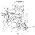
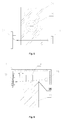
- Fig. 1 shows the structure of a motor metering pump (partially cut).
- the motor metering pump consists, as is generally known, essentially of three groups of components, namely the drive motor 2 with gear unit, the eccentric drive in the eccentric housing 1 and the electronics housing 28 with the electronic control contained therein and the electronic assemblies and components used therein.
- the electronics housing 28 has on the bottom of a bottom plate 4 with mounting holes, the eccentric housing 1, which is mounted on the electronics housing 28 and fixedly connected thereto, carries the drive motor 2 with gear unit, the e.g. connected via screws with the eccentric housing.
- the components of the eccentric drive are attached in an eccentric carrier 22, which ensures the positional alignment of the individual parts to one another and is fastened in the eccentric housing 1.
- a three-phase asynchronous motor 2 is flanged together with a reduction gear 11, which is designed as an angle gear, as a unit from the outside of the eccentric housing 1 and connected with screws.
- the output shaft of the geared motor forms a right angle to the shaft axis of the motor and either directly forms the drive shaft of the eccentric drive or, as in the described embodiment, is connected to the same axis via a clutch.
- the drive shaft of the eccentric drive, the eccentric shaft 17 is rotatably mounted in the eccentric carrier 22 and carries as an integral part with her an eccentric.
- the eccentric shaft penetrates with the eccentric a suitably cut push bar 20.
- the eccentric shaft 17 is rotated by the motor / gear unit via the shaft coupling with the motor 2 driven in rotation and further drives the push bar 20 on an inner surface of its section, namely the contact surface with the Outside surface of the eccentric on.
- the push bar 20 drives a fixedly connected to him, in the example injected, push rod 19 at.
- the unit of push bar 20 and push rod 19 is mounted longitudinally displaceable in two slide bushes.
- the axis of the eccentric shaft 17 and the longitudinal axis 18 of the push bar 20 and the push rod 19 are each in the horizontal plane and form a right angle to each other.
- One of the two sliding bushes 26 for the push rod 19 is seated in a bearing plate 24 which is attached to the eccentric carrier 22 on the printhead side;
- Achs convinced to the longitudinal axis 18 of the push rod 19 is a manually operated adjusting 7 for the adjustment of the Hubverstellbolzens 8 screwed into a thread of the Exzenterussis 22 that limits the axial movement of the push bar 20 during suction and thus the stroke of the metering pump.
- the housing further contains in its lower part in a closed space, the electronics housing 28, the electronic control.
- the housing is splash-proof and protects the eccentric drive and the electronic control against moisture or corrosion, as dosing pumps are often used in conjunction with chemically aggressive media.
- the electronic control consists of a horizontal control electronics 34 with the power switching stages for the motor driver 29, which are designed as an integrated frequency converter, and arranged in a housing cover 5 electronics 6, which contains the necessary for the operation of the metering input and display elements.
- the controls are protected by a cover 9. Below the cover 9 connections are provided for the control lines 10 and for the power supply.
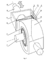
- a dosing head 12 On the side opposite the control lines 10 or the power supply connection, a dosing head 12 is arranged coaxially with the longitudinal axis 18 of the push rod, in which a dosing head 12 is provided as the displacement element. made of plastic membrane 13 works, which is firmly clamped at its periphery.
- the dosing head 12 also carries an inlet valve 14 and an outlet valve 15 in order to press the dosing medium sucked in via the inlet valve 14 between the diaphragm 13 and the dosing head 12 into the dosing line via the outlet valve 15.
- the motor metering pump operates on the volumetric principle, i. a predetermined volume should be sucked in each stroke on the one hand and on the other hand discharged via the exhaust valve 15.
- the diaphragm 13 is set in an oscillating motion by means of the eccentric drive which reciprocates the push rod 19 in the longitudinal axis.
- At the opposite end of the metering head 12 facing part of the push rod 19 is fixedly connected to the core 30 of the membrane 13 and puts them in an oscillating motion.
- a compression spring 23 for example, a coil spring is arranged, which engages the push bar 20 at any time form-fitting manner on the eccentric.
- the push bar is moved with the push rod towards the compression spring, at the same time the membrane 13 is pressed into the dosing chamber 16, with the result that an overpressure arises in the dosing space, the outlet valve 15, eg a spring-loaded ball valve, opens and the metering medium is forced into the metering line.
- the push bar 20 is moved by the compressed compression spring 23, which may be formed, for example, as a spiral spring following the eccentric movement in the opposite direction to Hubverstellbolzen 8, which
- the connecting rod 19 connected to the diaphragm 13 entrains the membrane in its movement, whereby a negative pressure is created in the dosing chamber 16, which opens the inlet valve 14, so that once again dosing medium can be sucked into the dosing chamber. Due to the alternating, oscillating movement of the diaphragm 13 by means of the eccentric drive, the delivery flow of the metering medium is formed in the metering line.
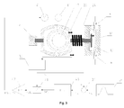
- the position of the unit consisting of push bar 20, push rod 19 and diaphragm 13 is scanned by the position sensor 36, the measurement signal is in a defined relationship to this position; this relationship may be considered as possible execution e.g. be strictly proportional.
- the measurement signal of the position sensor 36 always refers to the position of the part of the movable unit, where it acts. This point of attack is formed by the reference element, which in this context is to be understood in an abstract sense.
- it may be designed as a concrete component to be mounted in addition, but also only from a characteristic embodiment, e.g. an edge or surface on any of the components required anyway, e.g. on the push bar 20, exist.
- CCD charge coupled device
- a light source 33 e.g. a light emitting diode (LED)
- the sensor carrier 31 connected to the eccentric carrier and the components mounted thereon form a light barrier whose beam path is partially interrupted by the push bar.
- the reference element is formed by a shadow edge 35 of the push bar 20 in the region of the light barrier arrangement.
- the shadow edge 35 passes over the light-sensitive cells 32 in a contact-free manner.
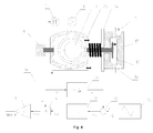
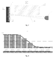
- FIG. 5 which shows a plan view in the axial direction
- the light source 33 must be arranged so that the light beam on its Way to the photosensitive cells 32 is not covered by the push rod 19; ie, that the light source 33 and the line of the photosensitive CCD cells 32 are arranged above or below the push rod 19.
- FIG. 5 which shows a plan view in the axial direction
- light source 33 is illuminated by means of the shadow edge 35 cast a shadow on the photosensitive cells 32, dividing the cells in principle into light (h) and non-illuminated (d) cells. Since the series of light-sensitive cells arranged parallel to the longitudinal axis 18, for example 128 pixels covering a distance of approximately 8 mm, is only partially exposed or shaded in the border area, the transitional situation of the shadow profile SV is shown in FIG. The height of the rectangular areas shown in FIG. 8 represents the illuminance of the respective pixels. By means of a special method, which will be described later in detail and explained with reference to FIG. 10, this limit situation is used to determine the respective position of the shadow edge and thus to determine the position of the push rod or the membrane exactly.
- This measuring device consisting of thrust-arm-side shadow edge and sensor carrier side light-sensitive CCD cells with opposite light source, serves to measure the actual position or the speed of the oscillating push rod and to use this information for the realization of the described functions.
- the push rod which causes the diaphragm to oscillate, travels a distance each stroke equaling the mechanical stroke length.
- the longitudinal extent of the photosensitive CCD cells must be slightly larger. In principle, this also applies to any other conceivable position sensor used.
- the movable part of the drive whose movement is to be controlled, consists of the push bar 20 with the push rod 19, with the diaphragm 30 is firmly connected.
- the return spring 23 retrieves the push bar after a successful stroke and thus causes the suction.
- the outer ring of the membrane 13 is fixedly mounted in the dosing head 12, the metal membrane core 30 injected into the membrane moves the central surface of the membrane as a displacement element in the dosing head.
- the inlet valve 14 closes on the suction side, the outlet valve 15 on the pressure side of the dosing and offers each a connection option for the outer casing.
- the reference element is a shadow edge 35 of the push bar 20 and the position sensor is a light barrier-like arrangement consisting of the previously described light source 33 in cooperation with the row of photosensitive cells 32, which detects the position of the shadow edge 35 optically and thus without contact by the shadowing. Since the push rod 19 ensures the actual connection and adhesion to the membrane 13 and push bar and push rod are firmly connected in the present example, the following description always refers to the movement of the push rod 19, although in fact the shadow edge 35 of the push bar 20 is measured ,
- the position sensor 36 outputs an actual signal x 1 which is proportional to the position of the reference element 35.
- this is derived in the exemplary embodiment by a differentiator 37 in time (dx I / dt) and thus additionally a speed-proportional actual signal v I formed.
- a time profile for the desired value 38 of the position x S or the speed v S is specified.
- PID controller controller with proportional, integral and differential components.
- the manipulated variable SG corresponds to a request value for the drive power.
- the manipulated variable SG is further processed by a position correction 41.
- the position correction 41 takes into account the fact that the speed of the motor is converted into a speed at the push rod, depending on the rotational angle position of the eccentric (to be deduced from the push rod position) in accordance with the sinusoidal characteristic of the eccentric drive.
- the position correction 41 calculates the output signal of the PID controller 40 via the inverse characteristic of the eccentric gear in a corrected manipulated variable KSG, which represents based on the input of the reduction gear 11, the necessary motor control, which is required to at the output of Exzentergetriebes to obtain a movement of the push rod 19 corresponding to the desired manipulated variable SG.
- An amplifier 42 which is designed as a frequency converter, includes the power switching stages and controls the motor according to the requested speed with the associated voltage and frequency.
- the amount of the position-dependent position correction, the conversion of the corrected manipulated variable KSG in a specific speed specification for the frequency converter and possibly the derivative constant for the formation of the speed signal v l are determined by the three proportionality factors k1, k2, k3.
- the factor for the position-dependent position correction k1 is to be selected in accordance with the characteristic of the eccentric gear, the two factors k2 for the power amplifier and k3 for the derivative of the speed signal can be selected based on practical considerations, such as working with as good manageable value ranges of the associated variables ,
- control loop for a position controller in Fig. 4, the control loop is shown schematically when used as a speed controller.
- the described control circuit sets the predetermined time profile for the desired value of the position x S or the speed v S , of course within the scope of its possible control accuracy.
- the membrane position can be controlled directly. This function makes it possible to selectively approach specific positions in selected dosing phases and, if necessary, to maintain them at standstill.
- Dosing pumps according to the prior art often provide a mode in which the dosing strokes carried out over the set volume of the displacement chamber (stroke length) are converted directly into a metered total volume and this. is displayed as volume flow in the unit l / h.
- stroke length the dosing strokes carried out over the set volume of the displacement chamber
- the position of the Hubverstellinnate must be converted for this purpose in metering pumps of previous design by a separate sensor into an electrical signal and read into the controller.
- An example of a practical realization would be a linear potentiometer on Hubverstellorgan 7, which scans its setting via a plunger.
- a metering pump that can detect the actually worn membrane path during the stroke using integrated position sensor 36 does not require an additional sensor. By subtraction of the two position values in the end positions, each after reaching the mechanical Can be measured stop, as soon as the movement has come to a halt, the stroke length can be calculated directly and is available for further processing.
- sensors are often used which emit a feedback pulse to the electronic controller for monitoring the metering movement per stroke.
- a known embodiment is e.g. a small permanent magnet, which is attached to the output shaft of the transmission, so on the eccentric shaft 17 outside the axis and rotates with this, in conjunction with a fixed Hall sensor that generates a signal when passing the magnet in a certain angular position of the eccentric shaft. Based on this signal, the electronic control measures the stroke period, which is identical to the cycle time of the eccentric shaft, and deduces from this a trouble-free sequence of the dosing process. In the event of a blockage in the course of the metering stroke due to an overpressure situation, e.g.
- the signal of the Hall sensor remains off and, after a monitoring period has elapsed, leads to a fault message and further reactions, e.g. Shutting down the dosing pump.
- the desired information is available only after the expiry of the monitoring time.
- the speed of the push rod 19 can be set in relation to the drive of the motor 2 at any time of Dosierhubs, and a blockage can be detected virtually instantaneously.
- Is used as drive motor 2 e.g. an asynchronous motor is used
- the effective mechanical speed at the motor output shaft under load is always slightly smaller than specified by the frequency of the electrical control.
- the difference between the two speeds, the so-called slip is dependent on parameters of the motor and within a reasonable load range approximately proportional to the load torque.
- the slip can be measured by various methods described below. From it, a correction value can be calculated, which can be included in the use of a frequency converter in the predetermined engine speed in the form of a frequency increase and thus compensated.
- the slip can be determined, for example, by comparing the measured stroke period with the predetermined by the electrical control.
- This method is also used in metering pumps according to the prior art by measuring the time interval between two Hall sensor pulses applied.
- a characteristic point along the stroke for example at halfway, is defined for period duration measurement, and the time at which this point is traversed is recorded for successive metering operations; the time difference between two such times is the period of the search.
- a more direct method for slip detection works with the observation of the instantaneous speed of push rod 19. From the motor speed predetermined by the electric drive, an ideal push rod speed can be calculated at any time via the known transmission and eccentric characteristics. By comparing the ideal and the measured speed, the slip can be determined at any time during the eccentric revolution and corrected by readjusting the frequency of the motor control.
- the force acting on the displacement element can be determined with the help of the slip determined according to one of the previously described methods, thus making it possible to draw conclusions about the working pressure of the metering medium.
- the eccentric transmits the force acting on the push rod 19 according to its sinusoidal characteristic depending on the instantaneous angular position via the gear 11 to the motor 2.
- the motor is decoupled from the push rod force, i. load-free, in the two points exactly in between the eccentric transmits the load torque maximum to the engine. Accordingly, assuming a constant push rod force, the torque to be applied to the motor output shaft and thus also the slip will approximate to a sine function.
- the fluctuation range is an image of the push rod force.
- the deviation of the stroke period from the ideal value is determined, this represents the slip averaged over the sinusoidal curve of the eccentric, which in turn represents a measure of the average stroke rod force, ie the working pressure. If the slip continuously determined from the comparison of the predetermined by the electrical control motor speed with the push rod speed, using the known eccentric and the knowledge of the instantaneous angle of rotation of the eccentric, which follows from the push rod position, the temporal force curve at the push rod 19 can be calculated. From the force curve at the push rod, in turn, the working pressure can be derived.
- the working pressure is determined by one of the methods described, it can be monitored for compliance with certain limits, and if the monitoring is activated, fault messages and further reactions, such Shutting down the dosing pump to be triggered.
- Over-limit monitoring may be used to protect the pump or other equipment; Occasionally, a factory preset limit of e.g. However, the monitoring limit may also be within the specified operating range of the metering pump when, for example, 130% of the maximum pressure of the metering pump is exceeded. more sensitive parts of the system are to be protected, and in this case must be specified by the operator. It is also possible to monitor for maintenance of given operating conditions; In this case, a fault message, e.g.
- a prevailing working pressure for example indicated by an operator
- a percentage up or down If the working pressure is set to maintain a minimum pressure of e.g. 1 bar monitored, it is thus possible to detect a leak caused by damage in the piping.
- the exact dosing capacity of motor metering pumps is influenced differently by the working pressure.
- the drive motor 2 if it is designed, for example, as an asynchronous motor, with increasing working pressure with increasing slip, which has a speed drop and an associated reduced stroke frequency.
- a membrane 13 used as a displacement element undergoes an elastic deformation under the influence of the working pressure during the metering stroke.
- the internal pressure is continuously increased in the metering chamber 16 while the exhaust valve 15 is still closed by the diaphragm member 30 is moved by the push rod 19 under pressure in the metering chamber 16 and the elastic flexing region of the membrane 13 to the same extent yielding to the pressure recedes in opposite directions to the movement of the diaphragm core 30.
- the membrane 13 deforms in itself, but in total there is virtually no change in volume, which is due to the fact that the metering medium is virtually incompressible and at this time both valves are closed.
- the chamber pressure corresponds to the external working pressure.
- the distance traveled so far of the push rod 19 corresponds to the amount of membrane deformation, ie the dead zone at the beginning of the dosage, and practically does not contribute to the dosage.
- the deformation or the dead zone typically moves in a range of approx. 0.1-0.5mm depending on diaphragm size, working pressure, etc.
- At the point of pressure balance opens the pressure-side outlet valve 15.
- the pressure acting on the diaphragm 13 is virtually identical to the external working pressure and remains, as the diaphragm deformation, for the rest Part of the dosing stroke approximately constant.
- the point of pressure equilibrium at which the pressure-side outlet valve opens marks the actual beginning of the metering so that the amount of membrane deformation is lost to the metering stroke, ie the effective stroke length is calculated from the mechanically predetermined minus the membrane deformation. Since the membrane deformation itself increases more or less proportionally with the working pressure, the typical dependency is a falling metering performance curve with increasing working pressure. The resulting negative deviation becomes more pronounced the smaller the set stroke length.
- the working pressure is determined according to one of the previously described methods, it is possible, based on the described dependencies, which can be determined quantitatively in preliminary tests for one type of device, to predetermine and compensate for the error-producing influence of the working pressure on the metering performance.
- a correction value which is added to the set stroke frequency. It should be noted that under practical and economic aspects only the systematic part of the influence can be eliminated.
- the pressure-dependent metering performance error is mainly determined by the material properties and dimensions of the components involved, which change to some extent due to aging may or may be subject to specimen discrepancies in the production series.
- the proportional error in the partial stroke operation is also eliminated so that the dosing pump is practically over the full usable setting range the stroke length of eg 20% -100% can be operated without having to perform the previously necessary recalibrations, which in a conventional metering pump with an adjustment of the stroke length by more than e.g. 10% are necessary to ensure the specified metering accuracy.
- the function of controlling the velocity of the displacer, here the membrane 13, can be used in particular for highly viscous media (for example lecithin) to limit flow losses in valves and other bottlenecks.
- Highly viscous media for example lecithin
- High flow rates have a negative influence on the dosing accuracy in such media by additional pressure losses due to flow resistance.
- it is advantageous here if the limited speed allows more time for the defined opening and closing of the valves. Overall, both effects improve the dosing accuracy of highly viscous media.
- the membrane velocity is kept limited to a selectable maximum value during the entire dosing process. This maximum speed depends i.a. from the viscosity of the concrete to be metered medium and is e.g. to be selected by the operator in the form of several pre-defined values adapted to common use cases or specified directly.
- slightly outgassing media such as sodium hypochlorite
- slightly outgassing media can be particularly at the intake, but also in the metering at too high flow velocity at bottlenecks by local undershooting of the vapor pressure, including the chemical composition of the metering As well as its temperature depends, cavitation occur, which has increased wear.
- Cavitation can be avoided by the speed is limited by control or even by simple speed specification to values well below a critical flow rate both in the pressure stroke and during the suction, ie the return of the diaphragm 13.
- the speed specification for the control loop or, in the simple case, the engine speed is set for this purpose so that the membrane velocity corresponding to the medium velocity is limited to, for example, 1 mm / 50 ms.
- the suction is prone to the formation of cavitation, since the static pressure is particularly low and therefore the safety range to below the vapor pressure is very low.
- Sensible values are for example 1mm / 50ms in the pressure stroke or 1mm / 100ms during suction, but of course different values are possible.
- Essential for such an individual treatment of the metering phases is that with the help of the position sensor, the exact position of the membrane is known at all times and thus the beginning of the (particularly critical) suction phase can be reliably detected.
- the invention makes it possible to save the mechanical device for adjusting the stroke length (adjusting member 7 and Hubverstellbolzen 8).
- the control device the desired stroke length electronically, eg by an operator input, communicated. If the desired stroke length has been carried out, the reached position of the diaphragm 13 is held by braking the motor 2 and these are then returned to the intake in the reversed direction of rotation of the motor.
- the following stroke can be carried out by further rotation of the engine beyond the suction-side dead center with a reversed direction of rotation (printing phase in reverse operation, suction in normal operation) or in the same order as the previous stroke; in the former case, deceleration and starting operations of the engine between the strokes and the associated time and energy requirements can be saved.
- the permanent change of direction makes it impossible for a passive fan fixedly mounted on the motor shaft to fulfill its function sufficiently, so that the use of an externally driven fan is indispensable for the motor if it requires cooling measures.
- the available time which results from the repetition frequency of the metering strokes, can be divided so that the portion remaining after deduction of the suction duration is utilized to a maximum for the forward movement, except for a short rest phase.
- the speed to be controlled is calculated from the distance to be traveled (set stroke length) and the available time.
- the instantaneous angular position of the Exzentergetriebes be reckoned and included in the engine speed so that the characteristic of the deflection device, which is sinusoidal when using an eccentric, balanced and the metering can be performed as exactly linear movement with a correspondingly constant application of the metering.
- the speed can be in a very wide range of e.g. 1 mm / min to 1 mm / s and beyond.
- CCD charge coupled device
- the active sensor elements described in more detail in this embodiment, which detect the position, are arranged on the side of the push arm 20 directed to the dosing head.
- the light source 33 is an LED
- the optical receiver is an electronic module with a CCD line 32, which are mounted here together on an intermediate part, the sensor carrier 31.
- the mounting on the sensor carrier 31 makes it possible to treat the position sensor 36 in the production process as an independent module and, for example, separately pre-assemble and check its function outside the final installation site.
- the described photocell-like arrangement is a touch and thus wear-free working sensor.
- the CCD module 32 is driven by an evaluation unit which contains a microprocessor and generates the required control signals.
- the evaluation unit can also be realized by a DSP (Digital Signal Processor) or in discrete technology.
- each component is suitable, which has a sufficiently narrow confined spot. Together with the imaging geometry shown in more detail in FIG. 7, this determines the width of the shadow area SV, see FIG. also Fig. 8.
- the light source 33 It is also possible to use a plurality of elements or a line emitter as the light source 33, with the aid of which the shadow profile SV can be specifically designed according to particular aspects. As an example, the achievement of a higher brightness, without affecting the image sharpness in the direction of movement.
- the control signals which are generated by the evaluation unit determine the exposure time, during which the individual pixels of the CCD line 32 integrate the incident light in each case in a separate amplifier within the CCD chip and cache for later evaluation. This integration occurs not only over the exposure time, but also across the photosensitive area of each pixel. After the exposure, the brightness values belonging to the pixels are successively read out of the CCD module by further control signals as analog values and detected by the evaluation unit.
- Exposure and readout of the brightness values take place alternately in the simple case.
- some commercially available CCD line components also offer options for simultaneous execution of both processes, by temporarily buffering the integrated measured values after exposure and enabling the integrators immediately for a subsequent measurement. By simultaneously reading out the results of a measurement run during the exposure phase for the subsequent passage, the measurement speed can be increased.
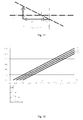
- the integrated brightness values H are shown corresponding to the actual shadow profile in the area of the addressed pixels in the specific embodiment.
- the shadow area SV extends over the pixels # 60 to # 63 in this example.
- a decision threshold H v (shown in Figure 8 as the dashed line.) Arbitrarily set at, for example half the maximum brightness and searched for the one pixel whose brightness value H, first, the threshold below the shadow transition H v; in the example this would be Pixel # 62.
- the brightness profile may be in opposite directions from unlit to illuminated CCD cells with increasing pixel number; On the one hand, this depends on the arrangement of the elements light source 33, CCD module 32 and shadow body 35 and on the other hand on the internal organization of the CCD 32 used. In this case, the pixel whose brightness value at the shadow transition first exceeds the threshold is searched for.
- a position value is available.
- the total time requirement of the three phases determines the repetition rate at which position values are obtained.
- the measurement resolution is equal to the pixel pitch R of the CCD line, corrected by the imaging ratio A, which results from the mounting distance with the individual components.
- the imaging ratio A is calculated to be 1.065.
- This deviation can easily be eliminated by a one-time calibration, eg during production.
- the linearity is determined almost exclusively by the accuracy of the pixel grid within the chip geometry, deviations are thus negligible.
- the two pixels to the left and to the right of the decision threshold H V are searched for and the distances ⁇ H of the associated brightness values are evaluated from this threshold.
- the intersection is 61.7. If the brightness progression in the interpolation range follows an ideal straight line, then both calculation paths lead to the same result, so it is basically sufficient to carry out one of the two calculations. However, with this property, error contributions can be minimized by a not exactly straight brightness curve in the considered transition range or by always expected measurement inaccuracies, for example by performing both calculations and averaging their results.
- the conditions on both sides of the point of intersection with respect to unlit and illuminated CCD cells can be reversed; in this case If necessary, the directions on the left and right change their function and the interpolation equations must be adjusted accordingly.
- the brightness values of more than two pixels are used for the calculation.
- the position can then be determined by redundant multiple calculation and e.g. Averaging several results are formed.
- a different linear interpolation than shown here or an interpolation with the data other than the direct neighbor pixels can be used.
- Deviations and displacements of linear parameters affect the result only within the interpolation range.
- the steepness of the brightness gradient in the shadow transition resulting from the sharpness of the image of the shadow edge on the CCD plane, is of subordinate importance since it does not affect the interpolation within wide limits; only the linearity of the brightness curve is decisive for the accuracy of the interpolation.
Landscapes
- Engineering & Computer Science (AREA)
- Mechanical Engineering (AREA)
- General Engineering & Computer Science (AREA)
- Computer Hardware Design (AREA)
- Reciprocating Pumps (AREA)
- Infusion, Injection, And Reservoir Apparatuses (AREA)
Applications Claiming Priority (1)
| Application Number | Priority Date | Filing Date | Title |
|---|---|---|---|
| DE102005039237A DE102005039237A1 (de) | 2005-08-19 | 2005-08-19 | Motordosierpumpe |
Publications (3)
| Publication Number | Publication Date |
|---|---|
| EP1754891A2 true EP1754891A2 (fr) | 2007-02-21 |
| EP1754891A3 EP1754891A3 (fr) | 2008-08-20 |
| EP1754891B1 EP1754891B1 (fr) | 2016-05-18 |
Family
ID=37081634
Family Applications (1)
| Application Number | Title | Priority Date | Filing Date |
|---|---|---|---|
| EP06119205.0A Active EP1754891B1 (fr) | 2005-08-19 | 2006-08-18 | Pompe de dosage |
Country Status (5)
| Country | Link |
|---|---|
| US (1) | US20070041845A1 (fr) |
| EP (1) | EP1754891B1 (fr) |
| JP (1) | JP2007051645A (fr) |
| DE (1) | DE102005039237A1 (fr) |
| ES (1) | ES2581979T3 (fr) |
Cited By (5)
| Publication number | Priority date | Publication date | Assignee | Title |
|---|---|---|---|---|
| DE102007027168A1 (de) * | 2007-06-13 | 2008-12-18 | Marco Systemanalyse Und Entwicklung Gmbh | Dosiervorrichtung |
| WO2011117199A1 (fr) | 2010-03-24 | 2011-09-29 | Prominent Dosiertechnik Gmbh | Procédé de commande et/ou de réglage d'une pompe de dosage |
| WO2017198458A1 (fr) * | 2016-05-17 | 2017-11-23 | Dürr Systems Ag | Pompe à agent de revêtement |
| WO2018015285A1 (fr) * | 2016-07-18 | 2018-01-25 | Prominent Gmbh | Dispositif de dosage comprenant une interface de communication |
| WO2018050525A1 (fr) * | 2016-09-15 | 2018-03-22 | Prominent Gmbh | Procédé pour faire fonctionner des appareils de dosage |
Families Citing this family (30)
| Publication number | Priority date | Publication date | Assignee | Title |
|---|---|---|---|---|
| US8540493B2 (en) | 2003-12-08 | 2013-09-24 | Sta-Rite Industries, Llc | Pump control system and method |
| US7854597B2 (en) | 2004-08-26 | 2010-12-21 | Pentair Water Pool And Spa, Inc. | Pumping system with two way communication |
| US7874808B2 (en) * | 2004-08-26 | 2011-01-25 | Pentair Water Pool And Spa, Inc. | Variable speed pumping system and method |
| US8469675B2 (en) * | 2004-08-26 | 2013-06-25 | Pentair Water Pool And Spa, Inc. | Priming protection |
| US8480373B2 (en) | 2004-08-26 | 2013-07-09 | Pentair Water Pool And Spa, Inc. | Filter loading |
| US8602745B2 (en) | 2004-08-26 | 2013-12-10 | Pentair Water Pool And Spa, Inc. | Anti-entrapment and anti-dead head function |
| US7686589B2 (en) | 2004-08-26 | 2010-03-30 | Pentair Water Pool And Spa, Inc. | Pumping system with power optimization |
| US8019479B2 (en) | 2004-08-26 | 2011-09-13 | Pentair Water Pool And Spa, Inc. | Control algorithm of variable speed pumping system |
| US7845913B2 (en) | 2004-08-26 | 2010-12-07 | Pentair Water Pool And Spa, Inc. | Flow control |
| SE529328C2 (sv) | 2005-11-15 | 2007-07-10 | Johan Stenberg | Styrsystem samt metod för styrning av elektromagnetiskt drivna pumpar |
| US20090288598A1 (en) * | 2008-05-21 | 2009-11-26 | Harris & Bruno Machine Co., Inc. | Doctor blade supply system with intelligent viscosity logic |
| ES2688385T3 (es) | 2008-10-06 | 2018-11-02 | Pentair Water Pool And Spa, Inc. | Método para operar un sistema de seguridad de liberación de vacío |
| US8425200B2 (en) | 2009-04-21 | 2013-04-23 | Xylem IP Holdings LLC. | Pump controller |
| US9556874B2 (en) | 2009-06-09 | 2017-01-31 | Pentair Flow Technologies, Llc | Method of controlling a pump and motor |
| US8564233B2 (en) | 2009-06-09 | 2013-10-22 | Sta-Rite Industries, Llc | Safety system and method for pump and motor |
| US20110081265A1 (en) * | 2009-10-06 | 2011-04-07 | Williams Hansford R | Pulse pump |
| CA2820887C (fr) | 2010-12-08 | 2019-10-22 | Pentair Water Pool And Spa, Inc. | Clapet de refoulement a depression pour un systeme brise-vide de securite |
| KR101893630B1 (ko) * | 2011-09-09 | 2018-08-30 | 그라코 미네소타 인크. | 전기 역전 모터를 갖춘 왕복 용적식 펌프 |
| US10465676B2 (en) | 2011-11-01 | 2019-11-05 | Pentair Water Pool And Spa, Inc. | Flow locking system and method |
| US9885360B2 (en) | 2012-10-25 | 2018-02-06 | Pentair Flow Technologies, Llc | Battery backup sump pump systems and methods |
| US10036378B2 (en) * | 2013-02-28 | 2018-07-31 | Ingersoll-Rand Company | Positive displacement pump with pressure compensating calibration |
| RU2674293C2 (ru) * | 2014-01-07 | 2018-12-06 | Флюид Хэндлинг ЭлЭлСи | Устройство с множеством насосов изменяемой скорости для обеспечения экономии энергии посредством расчета и компенсации потерь на трение, используя показатель скорости |
| US20150337816A1 (en) * | 2014-05-20 | 2015-11-26 | Ying Lin Cai | Eccentric roundel structure for compressing diaphragm pump with multiple effects |
| CN105443339A (zh) * | 2015-11-27 | 2016-03-30 | 苏州巧泰精密机械有限公司 | 计量泵往复驱动回位装置 |
| JP6892982B2 (ja) * | 2017-02-03 | 2021-06-23 | 応研精工株式会社 | ダイヤフラムポンプ |
| EP3591226B1 (fr) * | 2018-07-06 | 2022-02-16 | Grundfos Holding A/S | Pompe de dosage et procédé de commande d'une pompe de dosage |
| DE102018133214A1 (de) | 2018-12-20 | 2020-06-25 | Lutz-Jesco Gmbh | Dosierpumpe mit integriertem Überströmventil und Ventileinsatz für eine Dosierpumpe |
| DE102019215952A1 (de) * | 2019-10-16 | 2021-04-22 | Robert Bosch Gmbh | Membranpumpe, System und Verfahren zur optischen Bestimmung eines Auslenkungszustands einer Membran der Membranpumpe |
| CN114992080B (zh) * | 2022-06-01 | 2024-04-26 | 南京市水利规划设计院股份有限公司 | 一种水资源计量控制装置及其控制方法 |
| WO2024010798A2 (fr) * | 2022-07-08 | 2024-01-11 | Graco Minnesota Inc. | Pompe et dispositif de déplacement de fluide pour une pompe |
Citations (1)
| Publication number | Priority date | Publication date | Assignee | Title |
|---|---|---|---|---|
| EP0798558A2 (fr) | 1996-03-29 | 1997-10-01 | Shimadzu Corporation | Pompe à piston pour chromatographie en phase liquide à haute performance |
Family Cites Families (14)
| Publication number | Priority date | Publication date | Assignee | Title |
|---|---|---|---|---|
| US3756456A (en) * | 1972-05-22 | 1973-09-04 | Graco Inc | Apparatus and method for a metering system |
| DE2805946A1 (de) * | 1978-02-13 | 1979-08-16 | Bayer Ag | Vorrichtung zum dosieren mindestens zweier fliessfaehiger reaktionskomponenten in eine mischkammer |
| DE2937066A1 (de) * | 1979-09-13 | 1981-03-26 | Clinicon International Gmbh, 6800 Mannheim | Dosiervorrichtung |
| DE3139925A1 (de) * | 1981-10-08 | 1983-07-14 | Hewlett-Packard GmbH, 7030 Böblingen | Hochdruck-dosierpumpe |
| DE3320386A1 (de) * | 1983-06-06 | 1984-12-06 | Bran & Lübbe GmbH, 2000 Norderstedt | Kolben- oder kolbenmembranpumpe |
| DE3825295C2 (de) * | 1988-07-26 | 1994-05-11 | Heidelberger Druckmasch Ag | Vorrichtung zur Erfassung der Position einer Papierkante |
| US4971522A (en) * | 1989-05-11 | 1990-11-20 | Butlin Duncan M | Control system and method for AC motor driven cyclic load |
| US5280222A (en) * | 1989-06-01 | 1994-01-18 | Papst Motoren Gmbh & Co. Kg | Apparatus and method for controlling brushless electric motors and position encoders and indicating position thereof |
| US5056036A (en) * | 1989-10-20 | 1991-10-08 | Pulsafeeder, Inc. | Computer controlled metering pump |
| US5249932A (en) * | 1991-10-07 | 1993-10-05 | Erik Van Bork | Apparatus for controlling diaphragm extension in a diaphragm metering pump |
| JP3809661B2 (ja) * | 1995-12-28 | 2006-08-16 | ソニー株式会社 | 動き検出装置および動き検出方法 |
| JP3863292B2 (ja) * | 1998-05-29 | 2006-12-27 | シーケーディ株式会社 | 液体供給装置 |
| DE10139030A1 (de) * | 2000-08-29 | 2002-05-08 | Andreas Hindrichs | Messvorrichtung zum Vermessen eines Werkstückes |
| DE10322868A1 (de) * | 2003-05-21 | 2004-12-16 | Lang Apparatebau Gmbh | Verfahren zur Regelung einer von einem elektromotorisch angetriebenen Exzenter betätigten Membran- oder Kolbenpumpe |
-
2005
- 2005-08-19 DE DE102005039237A patent/DE102005039237A1/de not_active Ceased
-
2006
- 2006-08-18 ES ES06119205.0T patent/ES2581979T3/es active Active
- 2006-08-18 JP JP2006223507A patent/JP2007051645A/ja active Pending
- 2006-08-18 EP EP06119205.0A patent/EP1754891B1/fr active Active
- 2006-08-18 US US11/506,355 patent/US20070041845A1/en not_active Abandoned
Patent Citations (1)
| Publication number | Priority date | Publication date | Assignee | Title |
|---|---|---|---|---|
| EP0798558A2 (fr) | 1996-03-29 | 1997-10-01 | Shimadzu Corporation | Pompe à piston pour chromatographie en phase liquide à haute performance |
Cited By (7)
| Publication number | Priority date | Publication date | Assignee | Title |
|---|---|---|---|---|
| DE102007027168A1 (de) * | 2007-06-13 | 2008-12-18 | Marco Systemanalyse Und Entwicklung Gmbh | Dosiervorrichtung |
| WO2011117199A1 (fr) | 2010-03-24 | 2011-09-29 | Prominent Dosiertechnik Gmbh | Procédé de commande et/ou de réglage d'une pompe de dosage |
| DE102010003218A1 (de) | 2010-03-24 | 2011-09-29 | Prominent Dosiertechnik Gmbh | Verfahren zum Steuern und/oder Regeln einer Dosierpumpe |
| WO2017198458A1 (fr) * | 2016-05-17 | 2017-11-23 | Dürr Systems Ag | Pompe à agent de revêtement |
| WO2018015285A1 (fr) * | 2016-07-18 | 2018-01-25 | Prominent Gmbh | Dispositif de dosage comprenant une interface de communication |
| EP3485166B1 (fr) | 2016-07-18 | 2020-04-15 | ProMinent GmbH | Appareil de dosage avec une interface de communication |
| WO2018050525A1 (fr) * | 2016-09-15 | 2018-03-22 | Prominent Gmbh | Procédé pour faire fonctionner des appareils de dosage |
Also Published As
| Publication number | Publication date |
|---|---|
| JP2007051645A (ja) | 2007-03-01 |
| DE102005039237A1 (de) | 2007-02-22 |
| EP1754891A3 (fr) | 2008-08-20 |
| US20070041845A1 (en) | 2007-02-22 |
| EP1754891B1 (fr) | 2016-05-18 |
| ES2581979T3 (es) | 2016-09-08 |
Similar Documents
| Publication | Publication Date | Title |
|---|---|---|
| EP1754891B1 (fr) | Pompe de dosage | |
| EP1757809B1 (fr) | Pompe doseuse électromagnétique avec réglage du mouvement et de la vitesse | |
| DE4233243C2 (de) | Vorrichtung und Verfahren zur Steuerung des Drehmomentes eines bürstenlosen Gleichstrommotors | |
| EP2550454B1 (fr) | Procédé de commande d'une pompe doseuse | |
| DE202005013090U1 (de) | Motordosierpumpe | |
| EP0279931B1 (fr) | Pompe à membrane | |
| DE2759056C2 (fr) | ||
| EP1456539B1 (fr) | Pompe de dosage | |
| WO2007099000A1 (fr) | Procédé pour ajuster un piston dans un compresseur linéaire | |
| EP2184492B1 (fr) | Procédé destiné à la commande de pompe péristaltique | |
| CH654074A5 (de) | Mehrfach-kolbenpumpe mit konstanter foerderleistung. | |
| EP2913526A1 (fr) | Procédé de transport de fluide hydraulique et unité de pompe/moteur électrohydraulique associée | |
| DE202005013089U1 (de) | Magnetdosierpumpe | |
| EP3336351A1 (fr) | Pompe à chambre et procédé de fonctionnement d'une pompe à chambre | |
| DE2737062B1 (de) | Schubkolbenpumpe zur pulsationsfreien Foerderung einer Fluessigkeit | |
| WO2017198458A1 (fr) | Pompe à agent de revêtement | |
| EP2773265A1 (fr) | Appareil d'analyse portatif et son procédé d'utilisation | |
| DE2931017A1 (de) | Druckverstaerkersystem, insbesondere zur fluessigkeitsfoerderung in fluessigkeitschromatographen | |
| EP1299645B1 (fr) | Procede pour commander le moteur electrique d'une pompe de dosage | |
| EP0367099A2 (fr) | Pompe à piston à liquides pour appareils d'analyse chromatographique | |
| DE102016108120A1 (de) | Dosierpumpe und Verfahren zum Betreiben einer Dosierpumpe | |
| DE10033995A1 (de) | Verfahren zum Steuern einer elektromotorisch angetriebenen Dosierpumpe | |
| WO2010088780A1 (fr) | Vanne de dosage comportant un entraînement à moteur électrique | |
| EP1301710B1 (fr) | Pompe de dosage pourvue d'un moteur electrique | |
| DE10322404A1 (de) | Dosierpumpe und Verfahren zu deren Steuerung |
Legal Events
| Date | Code | Title | Description |
|---|---|---|---|
| PUAI | Public reference made under article 153(3) epc to a published international application that has entered the european phase |
Free format text: ORIGINAL CODE: 0009012 |
|
| AK | Designated contracting states |
Kind code of ref document: A2 Designated state(s): AT BE BG CH CY CZ DE DK EE ES FI FR GB GR HU IE IS IT LI LT LU LV MC NL PL PT RO SE SI SK TR |
|
| AX | Request for extension of the european patent |
Extension state: AL BA HR MK YU |
|
| PUAL | Search report despatched |
Free format text: ORIGINAL CODE: 0009013 |
|
| AK | Designated contracting states |
Kind code of ref document: A3 Designated state(s): AT BE BG CH CY CZ DE DK EE ES FI FR GB GR HU IE IS IT LI LT LU LV MC NL PL PT RO SE SI SK TR |
|
| AX | Request for extension of the european patent |
Extension state: AL BA HR MK RS |
|
| 17P | Request for examination filed |
Effective date: 20081205 |
|
| 17Q | First examination report despatched |
Effective date: 20090306 |
|
| AKX | Designation fees paid |
Designated state(s): AT BE BG CH CY CZ DE DK EE ES FI FR GB GR HU IE IS IT LI LT LU LV MC NL PL PT RO SE SI SK TR |
|
| GRAP | Despatch of communication of intention to grant a patent |
Free format text: ORIGINAL CODE: EPIDOSNIGR1 |
|
| INTG | Intention to grant announced |
Effective date: 20160210 |
|
| GRAS | Grant fee paid |
Free format text: ORIGINAL CODE: EPIDOSNIGR3 |
|
| GRAA | (expected) grant |
Free format text: ORIGINAL CODE: 0009210 |
|
| AK | Designated contracting states |
Kind code of ref document: B1 Designated state(s): AT BE BG CH CY CZ DE DK EE ES FI FR GB GR HU IE IS IT LI LT LU LV MC NL PL PT RO SE SI SK TR |
|
| REG | Reference to a national code |
Ref country code: GB Ref legal event code: FG4D Free format text: NOT ENGLISH |
|
| REG | Reference to a national code |
Ref country code: CH Ref legal event code: EP |
|
| REG | Reference to a national code |
Ref country code: IE Ref legal event code: FG4D Free format text: LANGUAGE OF EP DOCUMENT: GERMAN Ref country code: AT Ref legal event code: REF Ref document number: 800741 Country of ref document: AT Kind code of ref document: T Effective date: 20160615 |
|
| REG | Reference to a national code |
Ref country code: DE Ref legal event code: R096 Ref document number: 502006014950 Country of ref document: DE |
|
| REG | Reference to a national code |
Ref country code: FR Ref legal event code: PLFP Year of fee payment: 11 |
|
| REG | Reference to a national code |
Ref country code: ES Ref legal event code: FG2A Ref document number: 2581979 Country of ref document: ES Kind code of ref document: T3 Effective date: 20160908 |
|
| REG | Reference to a national code |
Ref country code: NL Ref legal event code: MP Effective date: 20160518 |
|
| REG | Reference to a national code |
Ref country code: LT Ref legal event code: MG4D |
|
| PG25 | Lapsed in a contracting state [announced via postgrant information from national office to epo] |
Ref country code: LT Free format text: LAPSE BECAUSE OF FAILURE TO SUBMIT A TRANSLATION OF THE DESCRIPTION OR TO PAY THE FEE WITHIN THE PRESCRIBED TIME-LIMIT Effective date: 20160518 Ref country code: NL Free format text: LAPSE BECAUSE OF FAILURE TO SUBMIT A TRANSLATION OF THE DESCRIPTION OR TO PAY THE FEE WITHIN THE PRESCRIBED TIME-LIMIT Effective date: 20160518 Ref country code: FI Free format text: LAPSE BECAUSE OF FAILURE TO SUBMIT A TRANSLATION OF THE DESCRIPTION OR TO PAY THE FEE WITHIN THE PRESCRIBED TIME-LIMIT Effective date: 20160518 |
|
| PG25 | Lapsed in a contracting state [announced via postgrant information from national office to epo] |
Ref country code: SE Free format text: LAPSE BECAUSE OF FAILURE TO SUBMIT A TRANSLATION OF THE DESCRIPTION OR TO PAY THE FEE WITHIN THE PRESCRIBED TIME-LIMIT Effective date: 20160518 Ref country code: LV Free format text: LAPSE BECAUSE OF FAILURE TO SUBMIT A TRANSLATION OF THE DESCRIPTION OR TO PAY THE FEE WITHIN THE PRESCRIBED TIME-LIMIT Effective date: 20160518 Ref country code: PT Free format text: LAPSE BECAUSE OF FAILURE TO SUBMIT A TRANSLATION OF THE DESCRIPTION OR TO PAY THE FEE WITHIN THE PRESCRIBED TIME-LIMIT Effective date: 20160919 Ref country code: GR Free format text: LAPSE BECAUSE OF FAILURE TO SUBMIT A TRANSLATION OF THE DESCRIPTION OR TO PAY THE FEE WITHIN THE PRESCRIBED TIME-LIMIT Effective date: 20160819 |
|
| PG25 | Lapsed in a contracting state [announced via postgrant information from national office to epo] |
Ref country code: BE Free format text: LAPSE BECAUSE OF NON-PAYMENT OF DUE FEES Effective date: 20160831 |
|
| PG25 | Lapsed in a contracting state [announced via postgrant information from national office to epo] |
Ref country code: CZ Free format text: LAPSE BECAUSE OF FAILURE TO SUBMIT A TRANSLATION OF THE DESCRIPTION OR TO PAY THE FEE WITHIN THE PRESCRIBED TIME-LIMIT Effective date: 20160518 Ref country code: SK Free format text: LAPSE BECAUSE OF FAILURE TO SUBMIT A TRANSLATION OF THE DESCRIPTION OR TO PAY THE FEE WITHIN THE PRESCRIBED TIME-LIMIT Effective date: 20160518 Ref country code: RO Free format text: LAPSE BECAUSE OF FAILURE TO SUBMIT A TRANSLATION OF THE DESCRIPTION OR TO PAY THE FEE WITHIN THE PRESCRIBED TIME-LIMIT Effective date: 20160518 Ref country code: EE Free format text: LAPSE BECAUSE OF FAILURE TO SUBMIT A TRANSLATION OF THE DESCRIPTION OR TO PAY THE FEE WITHIN THE PRESCRIBED TIME-LIMIT Effective date: 20160518 Ref country code: DK Free format text: LAPSE BECAUSE OF FAILURE TO SUBMIT A TRANSLATION OF THE DESCRIPTION OR TO PAY THE FEE WITHIN THE PRESCRIBED TIME-LIMIT Effective date: 20160518 |
|
| REG | Reference to a national code |
Ref country code: DE Ref legal event code: R097 Ref document number: 502006014950 Country of ref document: DE |
|
| PG25 | Lapsed in a contracting state [announced via postgrant information from national office to epo] |
Ref country code: PL Free format text: LAPSE BECAUSE OF FAILURE TO SUBMIT A TRANSLATION OF THE DESCRIPTION OR TO PAY THE FEE WITHIN THE PRESCRIBED TIME-LIMIT Effective date: 20160518 |
|
| PLBE | No opposition filed within time limit |
Free format text: ORIGINAL CODE: 0009261 |
|
| STAA | Information on the status of an ep patent application or granted ep patent |
Free format text: STATUS: NO OPPOSITION FILED WITHIN TIME LIMIT |
|
| PG25 | Lapsed in a contracting state [announced via postgrant information from national office to epo] |
Ref country code: MC Free format text: LAPSE BECAUSE OF FAILURE TO SUBMIT A TRANSLATION OF THE DESCRIPTION OR TO PAY THE FEE WITHIN THE PRESCRIBED TIME-LIMIT Effective date: 20160518 |
|
| REG | Reference to a national code |
Ref country code: CH Ref legal event code: PL |
|
| 26N | No opposition filed |
Effective date: 20170221 |
|
| PG25 | Lapsed in a contracting state [announced via postgrant information from national office to epo] |
Ref country code: LI Free format text: LAPSE BECAUSE OF NON-PAYMENT OF DUE FEES Effective date: 20160831 Ref country code: CH Free format text: LAPSE BECAUSE OF NON-PAYMENT OF DUE FEES Effective date: 20160831 |
|
| PG25 | Lapsed in a contracting state [announced via postgrant information from national office to epo] |
Ref country code: SI Free format text: LAPSE BECAUSE OF FAILURE TO SUBMIT A TRANSLATION OF THE DESCRIPTION OR TO PAY THE FEE WITHIN THE PRESCRIBED TIME-LIMIT Effective date: 20160518 |
|
| REG | Reference to a national code |
Ref country code: IE Ref legal event code: MM4A |
|
| PG25 | Lapsed in a contracting state [announced via postgrant information from national office to epo] |
Ref country code: IE Free format text: LAPSE BECAUSE OF NON-PAYMENT OF DUE FEES Effective date: 20160818 |
|
| REG | Reference to a national code |
Ref country code: FR Ref legal event code: PLFP Year of fee payment: 12 |
|
| PG25 | Lapsed in a contracting state [announced via postgrant information from national office to epo] |
Ref country code: LU Free format text: LAPSE BECAUSE OF NON-PAYMENT OF DUE FEES Effective date: 20160818 |
|
| REG | Reference to a national code |
Ref country code: AT Ref legal event code: MM01 Ref document number: 800741 Country of ref document: AT Kind code of ref document: T Effective date: 20160818 |
|
| PG25 | Lapsed in a contracting state [announced via postgrant information from national office to epo] |
Ref country code: AT Free format text: LAPSE BECAUSE OF NON-PAYMENT OF DUE FEES Effective date: 20160818 |
|
| PG25 | Lapsed in a contracting state [announced via postgrant information from national office to epo] |
Ref country code: HU Free format text: LAPSE BECAUSE OF FAILURE TO SUBMIT A TRANSLATION OF THE DESCRIPTION OR TO PAY THE FEE WITHIN THE PRESCRIBED TIME-LIMIT; INVALID AB INITIO Effective date: 20060818 Ref country code: CY Free format text: LAPSE BECAUSE OF FAILURE TO SUBMIT A TRANSLATION OF THE DESCRIPTION OR TO PAY THE FEE WITHIN THE PRESCRIBED TIME-LIMIT Effective date: 20160518 |
|
| PG25 | Lapsed in a contracting state [announced via postgrant information from national office to epo] |
Ref country code: IS Free format text: LAPSE BECAUSE OF FAILURE TO SUBMIT A TRANSLATION OF THE DESCRIPTION OR TO PAY THE FEE WITHIN THE PRESCRIBED TIME-LIMIT Effective date: 20160518 Ref country code: TR Free format text: LAPSE BECAUSE OF FAILURE TO SUBMIT A TRANSLATION OF THE DESCRIPTION OR TO PAY THE FEE WITHIN THE PRESCRIBED TIME-LIMIT Effective date: 20160518 |
|
| PG25 | Lapsed in a contracting state [announced via postgrant information from national office to epo] |
Ref country code: BG Free format text: LAPSE BECAUSE OF FAILURE TO SUBMIT A TRANSLATION OF THE DESCRIPTION OR TO PAY THE FEE WITHIN THE PRESCRIBED TIME-LIMIT Effective date: 20160518 |
|
| REG | Reference to a national code |
Ref country code: FR Ref legal event code: PLFP Year of fee payment: 13 |
|
| PGFP | Annual fee paid to national office [announced via postgrant information from national office to epo] |
Ref country code: GB Payment date: 20180822 Year of fee payment: 13 |
|
| PGFP | Annual fee paid to national office [announced via postgrant information from national office to epo] |
Ref country code: FR Payment date: 20190822 Year of fee payment: 14 |
|
| GBPC | Gb: european patent ceased through non-payment of renewal fee |
Effective date: 20190818 |
|
| PG25 | Lapsed in a contracting state [announced via postgrant information from national office to epo] |
Ref country code: GB Free format text: LAPSE BECAUSE OF NON-PAYMENT OF DUE FEES Effective date: 20190818 |
|
| REG | Reference to a national code |
Ref country code: ES Ref legal event code: FD2A Effective date: 20210108 |
|
| PG25 | Lapsed in a contracting state [announced via postgrant information from national office to epo] |
Ref country code: ES Free format text: LAPSE BECAUSE OF NON-PAYMENT OF DUE FEES Effective date: 20190819 |
|
| PG25 | Lapsed in a contracting state [announced via postgrant information from national office to epo] |
Ref country code: FR Free format text: LAPSE BECAUSE OF NON-PAYMENT OF DUE FEES Effective date: 20200831 |
|
| PGFP | Annual fee paid to national office [announced via postgrant information from national office to epo] |
Ref country code: IT Payment date: 20230825 Year of fee payment: 18 |
|
| PGFP | Annual fee paid to national office [announced via postgrant information from national office to epo] |
Ref country code: DE Payment date: 20230822 Year of fee payment: 18 |