EP1754254B1 - Lift pin with roller glide for reducing friction - Google Patents
Lift pin with roller glide for reducing friction Download PDFInfo
- Publication number
- EP1754254B1 EP1754254B1 EP05742317A EP05742317A EP1754254B1 EP 1754254 B1 EP1754254 B1 EP 1754254B1 EP 05742317 A EP05742317 A EP 05742317A EP 05742317 A EP05742317 A EP 05742317A EP 1754254 B1 EP1754254 B1 EP 1754254B1
- Authority
- EP
- European Patent Office
- Prior art keywords
- pin
- assembly according
- pin assembly
- lift
- roller glide
- Prior art date
- Legal status (The legal status is an assumption and is not a legal conclusion. Google has not performed a legal analysis and makes no representation as to the accuracy of the status listed.)
- Expired - Lifetime
Links
Images

Classifications
-
- H—ELECTRICITY
- H10—SEMICONDUCTOR DEVICES; ELECTRIC SOLID-STATE DEVICES NOT OTHERWISE PROVIDED FOR
- H10P—GENERIC PROCESSES OR APPARATUS FOR THE MANUFACTURE OR TREATMENT OF DEVICES COVERED BY CLASS H10
- H10P72/00—Handling or holding of wafers, substrates or devices during manufacture or treatment thereof
- H10P72/50—Handling or holding of wafers, substrates or devices during manufacture or treatment thereof for positioning, orientation or alignment
-
- H—ELECTRICITY
- H10—SEMICONDUCTOR DEVICES; ELECTRIC SOLID-STATE DEVICES NOT OTHERWISE PROVIDED FOR
- H10P—GENERIC PROCESSES OR APPARATUS FOR THE MANUFACTURE OR TREATMENT OF DEVICES COVERED BY CLASS H10
- H10P72/00—Handling or holding of wafers, substrates or devices during manufacture or treatment thereof
- H10P72/70—Handling or holding of wafers, substrates or devices during manufacture or treatment thereof for supporting or gripping
- H10P72/76—Handling or holding of wafers, substrates or devices during manufacture or treatment thereof for supporting or gripping using mechanical means, e.g. clamps or pinches
- H10P72/7604—Handling or holding of wafers, substrates or devices during manufacture or treatment thereof for supporting or gripping using mechanical means, e.g. clamps or pinches the wafers being placed on a susceptor, stage or support
- H10P72/7612—Handling or holding of wafers, substrates or devices during manufacture or treatment thereof for supporting or gripping using mechanical means, e.g. clamps or pinches the wafers being placed on a susceptor, stage or support characterised by lifting arrangements, e.g. lift pins
-
- C—CHEMISTRY; METALLURGY
- C23—COATING METALLIC MATERIAL; COATING MATERIAL WITH METALLIC MATERIAL; CHEMICAL SURFACE TREATMENT; DIFFUSION TREATMENT OF METALLIC MATERIAL; COATING BY VACUUM EVAPORATION, BY SPUTTERING, BY ION IMPLANTATION OR BY CHEMICAL VAPOUR DEPOSITION, IN GENERAL; INHIBITING CORROSION OF METALLIC MATERIAL OR INCRUSTATION IN GENERAL
- C23C—COATING METALLIC MATERIAL; COATING MATERIAL WITH METALLIC MATERIAL; SURFACE TREATMENT OF METALLIC MATERIAL BY DIFFUSION INTO THE SURFACE, BY CHEMICAL CONVERSION OR SUBSTITUTION; COATING BY VACUUM EVAPORATION, BY SPUTTERING, BY ION IMPLANTATION OR BY CHEMICAL VAPOUR DEPOSITION, IN GENERAL
- C23C16/00—Chemical coating by decomposition of gaseous compounds, without leaving reaction products of surface material in the coating, i.e. chemical vapour deposition [CVD] processes
- C23C16/44—Chemical coating by decomposition of gaseous compounds, without leaving reaction products of surface material in the coating, i.e. chemical vapour deposition [CVD] processes characterised by the method of coating
-
- C—CHEMISTRY; METALLURGY
- C23—COATING METALLIC MATERIAL; COATING MATERIAL WITH METALLIC MATERIAL; CHEMICAL SURFACE TREATMENT; DIFFUSION TREATMENT OF METALLIC MATERIAL; COATING BY VACUUM EVAPORATION, BY SPUTTERING, BY ION IMPLANTATION OR BY CHEMICAL VAPOUR DEPOSITION, IN GENERAL; INHIBITING CORROSION OF METALLIC MATERIAL OR INCRUSTATION IN GENERAL
- C23C—COATING METALLIC MATERIAL; COATING MATERIAL WITH METALLIC MATERIAL; SURFACE TREATMENT OF METALLIC MATERIAL BY DIFFUSION INTO THE SURFACE, BY CHEMICAL CONVERSION OR SUBSTITUTION; COATING BY VACUUM EVAPORATION, BY SPUTTERING, BY ION IMPLANTATION OR BY CHEMICAL VAPOUR DEPOSITION, IN GENERAL
- C23C16/00—Chemical coating by decomposition of gaseous compounds, without leaving reaction products of surface material in the coating, i.e. chemical vapour deposition [CVD] processes
- C23C16/44—Chemical coating by decomposition of gaseous compounds, without leaving reaction products of surface material in the coating, i.e. chemical vapour deposition [CVD] processes characterised by the method of coating
- C23C16/458—Chemical coating by decomposition of gaseous compounds, without leaving reaction products of surface material in the coating, i.e. chemical vapour deposition [CVD] processes characterised by the method of coating characterised by the method used for supporting substrates in the reaction chamber
- C23C16/4582—Rigid and flat substrates, e.g. plates or discs
- C23C16/4583—Rigid and flat substrates, e.g. plates or discs the substrate being supported substantially horizontally
- C23C16/4586—Elements in the interior of the support, e.g. electrodes, heating or cooling devices
Definitions
- the invention addresses pin systems that are used in vacuum chambers in general and in plasma enhanced chemical vapor deposition (PECVD) reactors in particular. These pins are used for lifting and supporting substrates in a reactor. When the reactor is open, the pins are elevated to receive the substrate, which is introduced by a robot fork. After the substrate has been placed on the pins, they are lowered until the substrate reaches the position in which the substrate is to be treated. There are also systems known in the art, where the reactor bottom is elevated relatively to the pins. The pins run in a guidance hole that is machined into the reactor bottom. Typically, the upper end of the guidance hole that disembogue to the reactor's interior is countersunk. Additionally, the pin head is flared to prevent the pins from falling through the guidance hole. The two latter characteristics of the pin system allow the pin head to be positioned close to flush with the reactor bottom. Usually, an elevator system consisting of a lift-arm and an elevator mechanism lifts the pin in the desired position.
- PECVD plasma enhanced chemical vapor deposition
- the pin self-locking is due to lateral forces that are applied on the pin. These lateral forces can be induced by the thermal expansion of the substrate when entering the heated chamber and the pin elevation system that pushes the pin not exactly in the guidance hole axis. High friction at the pin-substrate, pin-elevator and pin-guidance interfaces combined with insufficient guidance (poor pin to guide length ratio) amplify the pin-locking issue.
- the pin breakage can happen when the elevator pushes on a self-locked pin.
- US 2004/0045509 teach how to reduce the friction between the pin and its guidance hole.
- the solution is based on a pin design, where the pin has at least one larger diameter shoulder that reduces the contact area between the pin and its guidance hole, thereby reducing pin scratching, particle generation and component wear.
- a pin design is presented that decouples the lateral forces that are induced by a lift-arm.
- the pin system consists mainly of three parts; a lifting pin, an actuator pin and a lift arm.
- the lifting pin and the actuator pin are each guided in two bushings.
- the two pins are coaxial positioned in such a way that the actuator pin is used to move the lifting pin in the upper and lower end positions.
- a connector acts as an interface between the said pins. This connector allows for lateral clearance between the actuator pin and the lift pin.
- the actuator pin itself is moved by a lift-arm assembly that houses wear pads.
- the actuator pins are disposed on these wear pads that are larger in diameter as the actuator pin.
- the actuator pins may float laterally across the wear pads.
- the solutions presented in US 2004/0045509 and 2003/0205329 only partially solve the aforementioned technical problems.
- the first is designed to reduce the friction in the pin movement direction and the second is designed to reduce lateral forces on the pin systems that are induced by the elevator system.
- Prior art does not provide a solution that reduces the friction between the pin system and its guidance hole and the lateral forces that are induced by the elevator at the same time. Additionally, there is no known solution that decouples the lateral forces that are induced by the substrate.
- the present invention aims at reducing the lateral forces that are acting on the pin and the guidance friction during the elevation movement. Lateral forces can be induced by the lift-arm and the substrate.
- the elevator system consists of an lift-arm and a sole plate that is attached to the arm. The pin stands loose on the sole plate and resides in a bushing that is mounted on the reactor bottom. Therefore, the contact areas pin/substrate, pin/sole plate and pin/bushing are of primary interest.
- An inventive pin assembly for lifting and supporting substrates therefore comprises a lift pin (1) having a top and a bottom end; the top end being construed to receive and support a substrate (4); the bottom end being construed to be actuated by an elevator system (3a); the lift pin being movably sustained by a guide, wherein said guide comprises a roller glide to reduce the friction of the pin movement in a vertical axis.
- the roller glide comprises six rollers, arranged in a bushing and is being mounted on the reactor bottom.
- the bottom end of the lift pin (1) is, at least during the lifting operation, in contact with the the elevator system via a sole plate, comprising a top plate (7) being laterally movable relative to said elevator system.
- the sole plate further comprises a ball holding plate (8) with balls (9) being arranged beyond the top plate (7), which again may be laterally movable relative to said elevator system.
- the top end of the lift pin (1) further comprises a clearance being construed to hold a rolling ball (14) being supported by a ball bearing (13) and secured by a retaining ring.
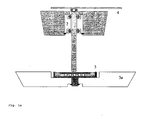
- Figure 1a shows the assembly of a pin system: A pin 1 is guided by the roller glide 2 and is actuated by the sole plate 3, which is mounted to a lift-arm 3a. At least three of these pin systems are applied for supporting and lifting a substrate 4.
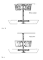
- the pins are supposed to receive the substrate 4 from a robot fork (not shown in Figure 1 ) that places the substrate on the elevating pins. Then, the pins pose the substrate 4 on the reactor bottom 2a ( Fig. 1b ). This is the substrate's final position before the coating process starts. After the coating process has ended, the pins lift the substrate in the elevated position ( Fig. 1 c) before a robot fork removes the substrate from the coating chamber.
- the inventive pin system comprises three elements: a roller glide, a ball bearing sole plate and a ball-bearing head pin.
- the first of the presented elements is the roller glide 2.
- This roller glide is designed for reducing the friction of the pin movement in a vertical axis.
- the roller glide is mounted on the reactor bottom 2a and guides the pin.
- the glide (see Fig. 2 ) consists of e. g. six rollers 6, 6 a, b, c that are made out of a material allowing low friction and low wear with the axis and bushing, chemically resistant against the process gases, and which keeps its properties at the process temperature.
- the rollers itself are held by bushing (5) made of such a material.
- a second element defines the interface between the pin and the elevator (see Fig. 3 ) : A ball bearing sole plate.
- This sole plate minimizes the lateral forces that could act on the pin.
- the lateral forces are induced by the lift-arm due to its lifting movement that does not match perfectly the pin's vertical movement axis.
- the sole plate comprises four main elements: the top plate 7 and the ball holding plate 8 that are elastically borne on the bottom plate 10. Balls 9 improve the top plate's lateral freedom of movement and hence minimize the lateral forces that act on the pin.
- the elastic bearing 7a, 8a of the top plate 7 and the ball holding plate 8 is needed for re-centering said two plates after one pin moving cycle.
- the restoring force of the elastic bearing e. g. a spring is a limiting factor for the lateral force that can be transmitted on the pin. Therefore, the spring constant should be relatively low to permit the floating movement of the top plate 7.
- the third element according to the invention is a pin ball-bearing head.
- the function of this modified pin head is to reduce the lateral forces that act on the pin. These forces may be introduced by the substrate.
- the pin head consists of a pin end 11 with a hemispherical clearance and a retaining ring 12, which holds a ball bearing 13 and a rolling ball 14.
- the rotational freedom of movement of the rolling ball 14 is enhanced by the ball bearing 13. Thereby, the lateral forces that can be induced by the substrate are minimized.
- the retaining ring (12) is slightly thicker than the pin shaft in order to prevent the pin from falling through the roller glide.
- the inventive pin design lowers the risk of self-locking considerably.
- the features of the new solution less guiding friction paired with decoupling of lateral forces, lead to a higher yield ratio and less downtime of the coating device.
- Additional positive effects are the reduction of particles in the reactor and the reduction of the risk to scratch the substrate. Thanks to the reduced friction of the pins, the abrasive forces between the pins and its guidance, as well as between the pins and the substrate are minimized. Particle contamination and the risk to scratch the substrate of the reactor are lowered.
Landscapes
- Chemical & Material Sciences (AREA)
- General Chemical & Material Sciences (AREA)
- Chemical Kinetics & Catalysis (AREA)
- Engineering & Computer Science (AREA)
- Materials Engineering (AREA)
- Mechanical Engineering (AREA)
- Metallurgy (AREA)
- Organic Chemistry (AREA)
- Container, Conveyance, Adherence, Positioning, Of Wafer (AREA)
- Liquid Crystal (AREA)
- Motorcycle And Bicycle Frame (AREA)
- User Interface Of Digital Computer (AREA)
- Manufacture Of Macromolecular Shaped Articles (AREA)
Abstract
Description
- The invention addresses pin systems that are used in vacuum chambers in general and in plasma enhanced chemical vapor deposition (PECVD) reactors in particular. These pins are used for lifting and supporting substrates in a reactor. When the reactor is open, the pins are elevated to receive the substrate, which is introduced by a robot fork. After the substrate has been placed on the pins, they are lowered until the substrate reaches the position in which the substrate is to be treated. There are also systems known in the art, where the reactor bottom is elevated relatively to the pins. The pins run in a guidance hole that is machined into the reactor bottom. Typically, the upper end of the guidance hole that disembogue to the reactor's interior is countersunk. Additionally, the pin head is flared to prevent the pins from falling through the guidance hole. The two latter characteristics of the pin system allow the pin head to be positioned close to flush with the reactor bottom. Usually, an elevator system consisting of a lift-arm and an elevator mechanism lifts the pin in the desired position.
- The current pin design, both geometry and materials, suffer from frequent pin self-locking and pin breakage. Both issues result in inhomogeneous deposition rates, substrate fracture and can even lead to a reactor shut-down.
- The pin self-locking is due to lateral forces that are applied on the pin. These lateral forces can be induced by the thermal expansion of the substrate when entering the heated chamber and the pin elevation system that pushes the pin not exactly in the guidance hole axis. High friction at the pin-substrate, pin-elevator and pin-guidance interfaces combined with insufficient guidance (poor pin to guide length ratio) amplify the pin-locking issue. The pin breakage can happen when the elevator pushes on a self-locked pin.
-
US 2004/0045509 teach how to reduce the friction between the pin and its guidance hole. The solution is based on a pin design, where the pin has at least one larger diameter shoulder that reduces the contact area between the pin and its guidance hole, thereby reducing pin scratching, particle generation and component wear. - Another attempt to reducing the lateral forces that act on the pin is described in
US application 2003/0205329 . Herein, a pin design is presented that decouples the lateral forces that are induced by a lift-arm. The pin system consists mainly of three parts; a lifting pin, an actuator pin and a lift arm. The lifting pin and the actuator pin are each guided in two bushings. The two pins are coaxial positioned in such a way that the actuator pin is used to move the lifting pin in the upper and lower end positions. A connector acts as an interface between the said pins. This connector allows for lateral clearance between the actuator pin and the lift pin. The actuator pin itself is moved by a lift-arm assembly that houses wear pads. The actuator pins are disposed on these wear pads that are larger in diameter as the actuator pin. The actuator pins may float laterally across the wear pads. - The solutions presented in
US 2004/0045509 and2003/0205329 only partially solve the aforementioned technical problems. The first is designed to reduce the friction in the pin movement direction and the second is designed to reduce lateral forces on the pin systems that are induced by the elevator system. - Prior art does not provide a solution that reduces the friction between the pin system and its guidance hole and the lateral forces that are induced by the elevator at the same time. Additionally, there is no known solution that decouples the lateral forces that are induced by the substrate.
- The present invention aims at reducing the lateral forces that are acting on the pin and the guidance friction during the elevation movement. Lateral forces can be induced by the lift-arm and the substrate. The elevator system consists of an lift-arm and a sole plate that is attached to the arm. The pin stands loose on the sole plate and resides in a bushing that is mounted on the reactor bottom. Therefore, the contact areas pin/substrate, pin/sole plate and pin/bushing are of primary interest.
- An inventive pin assembly for lifting and supporting substrates therefore comprises a lift pin (1) having a top and a bottom end; the top end being construed to receive and support a substrate (4); the bottom end being construed to be actuated by an elevator system (3a); the lift pin being movably sustained by a guide, wherein said guide comprises a roller glide to reduce the friction of the pin movement in a vertical axis. In further embodiments the roller glide comprises six rollers, arranged in a bushing and is being mounted on the reactor bottom. Furtheron the bottom end of the lift pin (1) is, at least during the lifting operation, in contact with the the elevator system via a sole plate, comprising a top plate (7) being laterally movable relative to said elevator system. The sole plate further comprises a ball holding plate (8) with balls (9) being arranged beyond the top plate (7), which again may be laterally movable relative to said elevator system. In a further aspect of the invention the top end of the lift pin (1) further comprises a clearance being construed to hold a rolling ball (14) being supported by a ball bearing (13) and secured by a retaining ring.
-
-
Fig. 1a ) shows an inventive support and lifting device employing three aspects of the invention. -
Fig. 1b ) shows a substrate on said inventive device in a bottom position -
Fig. 1c ) shows a substrate on said inventive device in a top position -
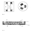
Fig. 2 shows a cross section through and a top view on a roller bearing bushing according to one aspect of the invention -
Fig. 3 shows ball bearing sole plate according to a further aspect of the invention -
Fig. 4 shows a ball bearing head according to a further aspect of the invention. -
Figure 1a shows the assembly of a pin system: A pin 1 is guided by theroller glide 2 and is actuated by thesole plate 3, which is mounted to a lift-arm 3a. At least three of these pin systems are applied for supporting and lifting a substrate 4. The pins are supposed to receive the substrate 4 from a robot fork (not shown inFigure 1 ) that places the substrate on the elevating pins. Then, the pins pose the substrate 4 on thereactor bottom 2a (Fig. 1b ). This is the substrate's final position before the coating process starts. After the coating process has ended, the pins lift the substrate in the elevated position (Fig. 1 c) before a robot fork removes the substrate from the coating chamber. - The inventive pin system comprises three elements: a roller glide, a ball bearing sole plate and a ball-bearing head pin.
- The first of the presented elements is the
roller glide 2. This roller glide is designed for reducing the friction of the pin movement in a vertical axis. The roller glide is mounted on thereactor bottom 2a and guides the pin. The glide (seeFig. 2 ) consists of e. g. six rollers 6, 6 a, b, c that are made out of a material allowing low friction and low wear with the axis and bushing, chemically resistant against the process gases, and which keeps its properties at the process temperature. The rollers itself are held by bushing (5) made of such a material. - A second element defines the interface between the pin and the elevator (see
Fig. 3 ) : A ball bearing sole plate. This sole plate minimizes the lateral forces that could act on the pin. The lateral forces are induced by the lift-arm due to its lifting movement that does not match perfectly the pin's vertical movement axis. The sole plate comprises four main elements: thetop plate 7 and theball holding plate 8 that are elastically borne on thebottom plate 10.Balls 9 improve the top plate's lateral freedom of movement and hence minimize the lateral forces that act on the pin. Theelastic bearing top plate 7 and theball holding plate 8 is needed for re-centering said two plates after one pin moving cycle. The restoring force of the elastic bearing, e. g. a spring is a limiting factor for the lateral force that can be transmitted on the pin. Therefore, the spring constant should be relatively low to permit the floating movement of thetop plate 7. - The third element according to the invention is a pin ball-bearing head. (
Fig. 4 ) The function of this modified pin head is to reduce the lateral forces that act on the pin. These forces may be introduced by the substrate. The pin head consists of apin end 11 with a hemispherical clearance and a retainingring 12, which holds aball bearing 13 and a rollingball 14. The rotational freedom of movement of the rollingball 14 is enhanced by theball bearing 13. Thereby, the lateral forces that can be induced by the substrate are minimized. The retaining ring (12) is slightly thicker than the pin shaft in order to prevent the pin from falling through the roller glide. - The inventive pin design lowers the risk of self-locking considerably. The features of the new solution, less guiding friction paired with decoupling of lateral forces, lead to a higher yield ratio and less downtime of the coating device. Additional positive effects are the reduction of particles in the reactor and the reduction of the risk to scratch the substrate. Thanks to the reduced friction of the pins, the abrasive forces between the pins and its guidance, as well as between the pins and the substrate are minimized. Particle contamination and the risk to scratch the substrate of the reactor are lowered.
- All these new characteristics increase the productivity and the quality of the coating process and hence increase the economic value to the user of such devices.
-
- 1
- pin, lift pin
- 2
- roller glide
- 2a
- reactor bottom
- 3
- plate
- 3a
- lift arm, elevator system
- 4
- substrate
- 5
- bushing
- 6
- roller
- 6a, b, c
- roller
- 7
- top plate
- 7a
- elastic bearing
- 8
- ball holding plate
- 8a
- elastic bearing
- 9
- ball(s)
- 10
- bottom plate
- 11
- pin end
- 12
- retaining ring
- 13
- ball bearing
- 14
- rolling ball
Claims (13)
- Pin assembly for lifting and supporting substrates comprising:- A lift pin (1) having a top and a bottom end;- the top end being construed to receive and support a substrate (4);- the bottom end being construed to be actuated by an elevator system (3a);- the lift pin (1) being movably sustained by a guide,wherein said guide comprises a roller glide (2) to reduce the friction of the pin movement in a vertical axis.
- Pin assembly according to claim 1, wherein the roller glide comprises six rollers (6) arranged in a bushing (5).
- Pin assembly according to claims 1 or 2, wherein the roller glide (2) is being mounted on a reactor bottom (2a).
- Pin assembly according to claims 1 to 3, wherein the roller glide (2) comprises rollers (6) made from material allowing low wear and low friction.
- Pin assembly according to claim 2, wherein the roller glide (2) and the bushing (5) are made of the same material.
- Pin assembly according to claim 1, wherein the bottom end of the lift pin (1) is, at least during the lifting operation, in contact with an elevator system (3a) via a sole plate (3).
- Pin assembly according to claim 6, wherein the sole plate (3) comprises a top plate (7) being laterally movable relative to said elevator system (3a).
- Pin Assembly according to claim 6 or 7, wherein the sole plate (3) further comprises a ball holding plate (8) with balls (9) being arranged beyond the top plate (7).
- Pin assembly according to claims 8, wherein the ball holding plate (8) is laterally movable relative to said elevator system.
- Pin assembly according to claims 7 or 9, wherein the lateral movement of top plate (7) and holding plate (8) is facilitated by elastic bearings (7a, 8a).
- Pin assembly according to claim 1, wherein the top end of the lift pin (1) further comprises a clearance being construed to hold a rolling ball (14).
- Pin assembly according to claim 11, wherein the rolling ball (14) is supported by a ball bearing (13).
- Pin assembly according to claim 11 or 12, further with a retaining ring (12) partially covering the clearance and preventing the lift pin from falling through the roller glide.
Applications Claiming Priority (2)
| Application Number | Priority Date | Filing Date | Title |
|---|---|---|---|
| US57515804P | 2004-05-28 | 2004-05-28 | |
| PCT/CH2005/000299 WO2005117097A1 (en) | 2004-05-28 | 2005-05-26 | Lift pin with roller glide for reducing friction |
Publications (2)
| Publication Number | Publication Date |
|---|---|
| EP1754254A1 EP1754254A1 (en) | 2007-02-21 |
| EP1754254B1 true EP1754254B1 (en) | 2008-05-28 |
Family
ID=34968080
Family Applications (1)
| Application Number | Title | Priority Date | Filing Date |
|---|---|---|---|
| EP05742317A Expired - Lifetime EP1754254B1 (en) | 2004-05-28 | 2005-05-26 | Lift pin with roller glide for reducing friction |
Country Status (9)
| Country | Link |
|---|---|
| US (1) | US20060016398A1 (en) |
| EP (1) | EP1754254B1 (en) |
| JP (1) | JP4777345B2 (en) |
| KR (1) | KR20070032960A (en) |
| AT (1) | ATE397288T1 (en) |
| DE (1) | DE602005007217D1 (en) |
| ES (1) | ES2304174T3 (en) |
| TW (1) | TWI393799B (en) |
| WO (1) | WO2005117097A1 (en) |
Families Citing this family (22)
| Publication number | Priority date | Publication date | Assignee | Title |
|---|---|---|---|---|
| US8033245B2 (en) * | 2004-02-12 | 2011-10-11 | Applied Materials, Inc. | Substrate support bushing |
| JP2007207807A (en) * | 2006-01-31 | 2007-08-16 | Hitachi Kokusai Electric Inc | Sample positioning device |
| JP4855097B2 (en) * | 2006-02-14 | 2012-01-18 | 株式會社塩山製作所 | Semiconductor chip separator |
| KR101404009B1 (en) * | 2007-12-21 | 2014-06-13 | 주성엔지니어링(주) | Lift pin assembly |
| KR100945178B1 (en) * | 2008-04-24 | 2010-03-03 | 이옥기 | Bushing for feeder |
| US9011602B2 (en) * | 2009-01-29 | 2015-04-21 | Lam Research Corporation | Pin lifting system |
| WO2011009007A2 (en) * | 2009-07-15 | 2011-01-20 | Applied Materials, Inc. | Improved lift pin guides |
| JP5549441B2 (en) * | 2010-01-14 | 2014-07-16 | 東京エレクトロン株式会社 | Holder mechanism, load lock device, processing device, and transport mechanism |
| KR101053565B1 (en) * | 2010-10-11 | 2011-08-03 | (주) 에스디시 | Lifting pin guide |
| US9371584B2 (en) * | 2011-03-09 | 2016-06-21 | Applied Materials, Inc. | Processing chamber and method for centering a substrate therein |
| WO2012157638A1 (en) * | 2011-05-19 | 2012-11-22 | シャープ株式会社 | Substrate placing base and substrate processing device |
| CN103828035B (en) * | 2011-10-20 | 2016-11-23 | 应用材料公司 | Substrate supports axle bush |
| KR101432152B1 (en) * | 2012-11-13 | 2014-08-22 | 삼성디스플레이 주식회사 | Substrate supporting module |
| CN105039934A (en) * | 2015-09-15 | 2015-11-11 | 京东方科技集团股份有限公司 | Rolling wheel sleeve |
| KR101764418B1 (en) | 2016-01-06 | 2017-08-02 | (주)신산이엔지 | Substrate supporting device |
| US10998219B2 (en) * | 2016-06-13 | 2021-05-04 | Taiwan Semiconductor Manufacturing Co., Ltd. | Wafer support device and method for removing lift pin therefrom |
| WO2019185124A1 (en) * | 2018-03-27 | 2019-10-03 | Vat Holding Ag | Pin lifting device having a coupling for receiving and releasing a support pin |
| CN111029236A (en) * | 2018-10-09 | 2020-04-17 | 北京北方华创微电子装备有限公司 | Supporting device and reaction chamber |
| JP7147527B2 (en) | 2018-12-10 | 2022-10-05 | トヨタ自動車株式会社 | Support device, support method and program |
| KR20250164864A (en) * | 2019-11-22 | 2025-11-25 | 램 리써치 코포레이션 | Coin-slot and ball-lock ceramic lift pin holders |
| CN113764328B (en) | 2020-06-02 | 2024-06-21 | 拓荆科技股份有限公司 | Device and method for processing wafer |
| DE102020120732A1 (en) * | 2020-08-06 | 2022-02-10 | Vat Holding Ag | pin lifting device |
Family Cites Families (21)
| Publication number | Priority date | Publication date | Assignee | Title |
|---|---|---|---|---|
| US3887247A (en) * | 1974-02-25 | 1975-06-03 | Us Energy | Bearing mounting for telescoping tubes |
| JP3249765B2 (en) * | 1997-05-07 | 2002-01-21 | 東京エレクトロン株式会社 | Substrate processing equipment |
| JP3028462B2 (en) * | 1995-05-12 | 2000-04-04 | 東京エレクトロン株式会社 | Heat treatment equipment |
| JP3354367B2 (en) * | 1995-12-19 | 2002-12-09 | 大日本スクリーン製造株式会社 | Substrate cleaning device |
| JP3940190B2 (en) * | 1996-09-30 | 2007-07-04 | 松下電器産業株式会社 | Vacuum processing equipment |
| US5672010A (en) * | 1996-11-18 | 1997-09-30 | Macnicol; Allan E. | Linear slide bearing apparatus |
| US5848670A (en) * | 1996-12-04 | 1998-12-15 | Applied Materials, Inc. | Lift pin guidance apparatus |
| JP3456890B2 (en) * | 1998-01-16 | 2003-10-14 | 東京エレクトロン株式会社 | Substrate processing equipment |
| JPH11351250A (en) * | 1998-06-12 | 1999-12-24 | Sony Corp | Bearing device |
| JP3398936B2 (en) * | 1999-04-09 | 2003-04-21 | 日本エー・エス・エム株式会社 | Semiconductor processing equipment |
| JP4402763B2 (en) * | 1999-05-13 | 2010-01-20 | Sumco Techxiv株式会社 | Epitaxial wafer manufacturing equipment |
| JP2001093960A (en) * | 1999-09-22 | 2001-04-06 | Hitachi Techno Eng Co Ltd | Wafer positioning device for processing equipment |
| US6958098B2 (en) * | 2000-02-28 | 2005-10-25 | Applied Materials, Inc. | Semiconductor wafer support lift-pin assembly |
| US20030072639A1 (en) * | 2001-10-17 | 2003-04-17 | Applied Materials, Inc. | Substrate support |
| JP4111703B2 (en) * | 2001-10-19 | 2008-07-02 | アプライド マテリアルズ インコーポレイテッド | Wafer lift mechanism |
| JP2003197719A (en) * | 2001-12-21 | 2003-07-11 | Komatsu Electronic Metals Co Ltd | Semiconductor manufacturing apparatus and substrate support structure |
| JP2004026365A (en) * | 2002-06-24 | 2004-01-29 | Dainippon Printing Co Ltd | Workbench |
| DE10232478A1 (en) * | 2002-07-17 | 2004-02-12 | Infineon Technologies Ag | Wafer lifting device for semiconductor electronics and chip production and testing has guides for lifting pins which are attached to the wafer holder |
| US6887317B2 (en) * | 2002-09-10 | 2005-05-03 | Applied Materials, Inc. | Reduced friction lift pin |
| JP4175988B2 (en) * | 2002-10-25 | 2008-11-05 | 東京エレクトロン株式会社 | Substrate alignment apparatus, substrate processing apparatus, and substrate transfer apparatus |
| US8033245B2 (en) * | 2004-02-12 | 2011-10-11 | Applied Materials, Inc. | Substrate support bushing |
-
2005
- 2005-05-25 US US11/137,230 patent/US20060016398A1/en not_active Abandoned
- 2005-05-26 EP EP05742317A patent/EP1754254B1/en not_active Expired - Lifetime
- 2005-05-26 DE DE602005007217T patent/DE602005007217D1/en not_active Expired - Lifetime
- 2005-05-26 KR KR1020067027409A patent/KR20070032960A/en not_active Withdrawn
- 2005-05-26 ES ES05742317T patent/ES2304174T3/en not_active Expired - Lifetime
- 2005-05-26 JP JP2007513650A patent/JP4777345B2/en not_active Expired - Fee Related
- 2005-05-26 AT AT05742317T patent/ATE397288T1/en not_active IP Right Cessation
- 2005-05-26 WO PCT/CH2005/000299 patent/WO2005117097A1/en not_active Ceased
- 2005-05-27 TW TW094117365A patent/TWI393799B/en not_active IP Right Cessation
Also Published As
| Publication number | Publication date |
|---|---|
| DE602005007217D1 (en) | 2008-07-10 |
| WO2005117097A1 (en) | 2005-12-08 |
| ATE397288T1 (en) | 2008-06-15 |
| JP4777345B2 (en) | 2011-09-21 |
| US20060016398A1 (en) | 2006-01-26 |
| JP2008500709A (en) | 2008-01-10 |
| EP1754254A1 (en) | 2007-02-21 |
| ES2304174T3 (en) | 2008-09-16 |
| TWI393799B (en) | 2013-04-21 |
| KR20070032960A (en) | 2007-03-23 |
| TW200624587A (en) | 2006-07-16 |
Similar Documents
| Publication | Publication Date | Title |
|---|---|---|
| US20060016398A1 (en) | Supporting and lifting device for substrates in vacuum | |
| US11887879B2 (en) | In-situ apparatus for semiconductor process module | |
| US8216422B2 (en) | Substrate support bushing | |
| US5820685A (en) | Wafer support device | |
| US5951776A (en) | Self aligning lift mechanism | |
| US10325799B2 (en) | Dual temperature heater | |
| JP5059019B2 (en) | Mold press mold and method for producing molded body | |
| US20110164955A1 (en) | Processing chamber with translating wear plate for lift pin | |
| US12347719B2 (en) | Floating pin for substrate transfer | |
| WO2011009007A2 (en) | Improved lift pin guides | |
| CN112736014A (en) | Wafer locking mechanism for locking wafer, wafer positioning device and wafer conveying equipment | |
| TWI820174B (en) | Electrically isolated pin-lifter | |
| KR20190057404A (en) | Wafer positioning for semiconductor processing Pad lift mechanism of pedestal | |
| KR102614453B1 (en) | High pressure wafer processing apparatus | |
| KR20090056204A (en) | Board Lift Device | |
| CN114620637B (en) | Lifting device and lifter assembly with same | |
| CN112447580A (en) | Pin lifter with sliding guide | |
| KR100375984B1 (en) | plate assembly and apparatus having the same | |
| JP2008239467A (en) | Molding die for press molding and manufacture method of molded product | |
| TW202310076A (en) | Methods for processing a semiconductor substrate | |
| CN104944160B (en) | Conveyors and Conveyor Systems | |
| KR101207771B1 (en) | Lift pin holder reducing friction force | |
| KR101381207B1 (en) | Substrate support pin holder having movable part and substrate processing apparatus comprising the same | |
| CN219808004U (en) | A wafer lifting structure and thin film deposition equipment | |
| CN224234174U (en) | Wafer lifting device and semiconductor device |
Legal Events
| Date | Code | Title | Description |
|---|---|---|---|
| PUAI | Public reference made under article 153(3) epc to a published international application that has entered the european phase |
Free format text: ORIGINAL CODE: 0009012 |
|
| 17P | Request for examination filed |
Effective date: 20061228 |
|
| AK | Designated contracting states |
Kind code of ref document: A1 Designated state(s): AT BE BG CH CY CZ DE DK EE ES FI FR GB GR HU IE IS IT LI LT LU MC NL PL PT RO SE SI SK TR |
|
| RIN1 | Information on inventor provided before grant (corrected) |
Inventor name: HERNANDEZ, SYLVAIN Inventor name: SCHMITT, JACQUES Inventor name: JAEGER, HANS Inventor name: EL BOUCHIKHY, REDOUANE Inventor name: LANDRY, KARINE Inventor name: DUBOST, LAURENT Inventor name: ZAPODEANU, EUGENE Inventor name: VINEL, BERTRAND |
|
| DAX | Request for extension of the european patent (deleted) | ||
| GRAP | Despatch of communication of intention to grant a patent |
Free format text: ORIGINAL CODE: EPIDOSNIGR1 |
|
| GRAS | Grant fee paid |
Free format text: ORIGINAL CODE: EPIDOSNIGR3 |
|
| GRAA | (expected) grant |
Free format text: ORIGINAL CODE: 0009210 |
|
| AK | Designated contracting states |
Kind code of ref document: B1 Designated state(s): AT BE BG CH CY CZ DE DK EE ES FI FR GB GR HU IE IS IT LI LT LU MC NL PL PT RO SE SI SK TR |
|
| REG | Reference to a national code |
Ref country code: GB Ref legal event code: FG4D |
|
| REG | Reference to a national code |
Ref country code: CH Ref legal event code: EP |
|
| REF | Corresponds to: |
Ref document number: 602005007217 Country of ref document: DE Date of ref document: 20080710 Kind code of ref document: P |
|
| REG | Reference to a national code |
Ref country code: IE Ref legal event code: FG4D |
|
| REG | Reference to a national code |
Ref country code: ES Ref legal event code: FG2A Ref document number: 2304174 Country of ref document: ES Kind code of ref document: T3 |
|
| PG25 | Lapsed in a contracting state [announced via postgrant information from national office to epo] |
Ref country code: SI Free format text: LAPSE BECAUSE OF FAILURE TO SUBMIT A TRANSLATION OF THE DESCRIPTION OR TO PAY THE FEE WITHIN THE PRESCRIBED TIME-LIMIT Effective date: 20080528 |
|
| PG25 | Lapsed in a contracting state [announced via postgrant information from national office to epo] |
Ref country code: FI Free format text: LAPSE BECAUSE OF FAILURE TO SUBMIT A TRANSLATION OF THE DESCRIPTION OR TO PAY THE FEE WITHIN THE PRESCRIBED TIME-LIMIT Effective date: 20080528 |
|
| PG25 | Lapsed in a contracting state [announced via postgrant information from national office to epo] |
Ref country code: AT Free format text: LAPSE BECAUSE OF FAILURE TO SUBMIT A TRANSLATION OF THE DESCRIPTION OR TO PAY THE FEE WITHIN THE PRESCRIBED TIME-LIMIT Effective date: 20080528 Ref country code: NL Free format text: LAPSE BECAUSE OF FAILURE TO SUBMIT A TRANSLATION OF THE DESCRIPTION OR TO PAY THE FEE WITHIN THE PRESCRIBED TIME-LIMIT Effective date: 20080528 |
|
| NLV1 | Nl: lapsed or annulled due to failure to fulfill the requirements of art. 29p and 29m of the patents act | ||
| ET | Fr: translation filed | ||
| PG25 | Lapsed in a contracting state [announced via postgrant information from national office to epo] |
Ref country code: IS Free format text: LAPSE BECAUSE OF FAILURE TO SUBMIT A TRANSLATION OF THE DESCRIPTION OR TO PAY THE FEE WITHIN THE PRESCRIBED TIME-LIMIT Effective date: 20080928 |
|
| PG25 | Lapsed in a contracting state [announced via postgrant information from national office to epo] |
Ref country code: DK Free format text: LAPSE BECAUSE OF FAILURE TO SUBMIT A TRANSLATION OF THE DESCRIPTION OR TO PAY THE FEE WITHIN THE PRESCRIBED TIME-LIMIT Effective date: 20080528 Ref country code: LT Free format text: LAPSE BECAUSE OF FAILURE TO SUBMIT A TRANSLATION OF THE DESCRIPTION OR TO PAY THE FEE WITHIN THE PRESCRIBED TIME-LIMIT Effective date: 20080528 Ref country code: CZ Free format text: LAPSE BECAUSE OF FAILURE TO SUBMIT A TRANSLATION OF THE DESCRIPTION OR TO PAY THE FEE WITHIN THE PRESCRIBED TIME-LIMIT Effective date: 20080528 Ref country code: SE Free format text: LAPSE BECAUSE OF FAILURE TO SUBMIT A TRANSLATION OF THE DESCRIPTION OR TO PAY THE FEE WITHIN THE PRESCRIBED TIME-LIMIT Effective date: 20080828 |
|
| PG25 | Lapsed in a contracting state [announced via postgrant information from national office to epo] |
Ref country code: RO Free format text: LAPSE BECAUSE OF FAILURE TO SUBMIT A TRANSLATION OF THE DESCRIPTION OR TO PAY THE FEE WITHIN THE PRESCRIBED TIME-LIMIT Effective date: 20080528 Ref country code: SK Free format text: LAPSE BECAUSE OF FAILURE TO SUBMIT A TRANSLATION OF THE DESCRIPTION OR TO PAY THE FEE WITHIN THE PRESCRIBED TIME-LIMIT Effective date: 20080528 Ref country code: BE Free format text: LAPSE BECAUSE OF FAILURE TO SUBMIT A TRANSLATION OF THE DESCRIPTION OR TO PAY THE FEE WITHIN THE PRESCRIBED TIME-LIMIT Effective date: 20080528 Ref country code: PT Free format text: LAPSE BECAUSE OF FAILURE TO SUBMIT A TRANSLATION OF THE DESCRIPTION OR TO PAY THE FEE WITHIN THE PRESCRIBED TIME-LIMIT Effective date: 20081028 |
|
| PLBE | No opposition filed within time limit |
Free format text: ORIGINAL CODE: 0009261 |
|
| STAA | Information on the status of an ep patent application or granted ep patent |
Free format text: STATUS: NO OPPOSITION FILED WITHIN TIME LIMIT |
|
| PG25 | Lapsed in a contracting state [announced via postgrant information from national office to epo] |
Ref country code: BG Free format text: LAPSE BECAUSE OF FAILURE TO SUBMIT A TRANSLATION OF THE DESCRIPTION OR TO PAY THE FEE WITHIN THE PRESCRIBED TIME-LIMIT Effective date: 20080828 Ref country code: EE Free format text: LAPSE BECAUSE OF FAILURE TO SUBMIT A TRANSLATION OF THE DESCRIPTION OR TO PAY THE FEE WITHIN THE PRESCRIBED TIME-LIMIT Effective date: 20080528 |
|
| 26N | No opposition filed |
Effective date: 20090303 |
|
| PGFP | Annual fee paid to national office [announced via postgrant information from national office to epo] |
Ref country code: ES Payment date: 20090605 Year of fee payment: 5 |
|
| PGFP | Annual fee paid to national office [announced via postgrant information from national office to epo] |
Ref country code: IT Payment date: 20090520 Year of fee payment: 5 |
|
| PGFP | Annual fee paid to national office [announced via postgrant information from national office to epo] |
Ref country code: GB Payment date: 20090520 Year of fee payment: 5 |
|
| PG25 | Lapsed in a contracting state [announced via postgrant information from national office to epo] |
Ref country code: MC Free format text: LAPSE BECAUSE OF NON-PAYMENT OF DUE FEES Effective date: 20090531 |
|
| REG | Reference to a national code |
Ref country code: CH Ref legal event code: PL |
|
| PG25 | Lapsed in a contracting state [announced via postgrant information from national office to epo] |
Ref country code: CH Free format text: LAPSE BECAUSE OF NON-PAYMENT OF DUE FEES Effective date: 20090531 Ref country code: LI Free format text: LAPSE BECAUSE OF NON-PAYMENT OF DUE FEES Effective date: 20090531 |
|
| REG | Reference to a national code |
Ref country code: IE Ref legal event code: MM4A |
|
| PG25 | Lapsed in a contracting state [announced via postgrant information from national office to epo] |
Ref country code: IE Free format text: LAPSE BECAUSE OF NON-PAYMENT OF DUE FEES Effective date: 20090526 |
|
| PG25 | Lapsed in a contracting state [announced via postgrant information from national office to epo] |
Ref country code: PL Free format text: LAPSE BECAUSE OF FAILURE TO SUBMIT A TRANSLATION OF THE DESCRIPTION OR TO PAY THE FEE WITHIN THE PRESCRIBED TIME-LIMIT Effective date: 20080528 |
|
| PG25 | Lapsed in a contracting state [announced via postgrant information from national office to epo] |
Ref country code: GR Free format text: LAPSE BECAUSE OF FAILURE TO SUBMIT A TRANSLATION OF THE DESCRIPTION OR TO PAY THE FEE WITHIN THE PRESCRIBED TIME-LIMIT Effective date: 20080829 |
|
| GBPC | Gb: european patent ceased through non-payment of renewal fee |
Effective date: 20100526 |
|
| PG25 | Lapsed in a contracting state [announced via postgrant information from national office to epo] |
Ref country code: IT Free format text: LAPSE BECAUSE OF NON-PAYMENT OF DUE FEES Effective date: 20100526 |
|
| PG25 | Lapsed in a contracting state [announced via postgrant information from national office to epo] |
Ref country code: LU Free format text: LAPSE BECAUSE OF NON-PAYMENT OF DUE FEES Effective date: 20090526 |
|
| PG25 | Lapsed in a contracting state [announced via postgrant information from national office to epo] |
Ref country code: HU Free format text: LAPSE BECAUSE OF FAILURE TO SUBMIT A TRANSLATION OF THE DESCRIPTION OR TO PAY THE FEE WITHIN THE PRESCRIBED TIME-LIMIT Effective date: 20081129 |
|
| REG | Reference to a national code |
Ref country code: ES Ref legal event code: FD2A Effective date: 20110711 |
|
| PG25 | Lapsed in a contracting state [announced via postgrant information from national office to epo] |
Ref country code: ES Free format text: LAPSE BECAUSE OF NON-PAYMENT OF DUE FEES Effective date: 20110629 Ref country code: GB Free format text: LAPSE BECAUSE OF NON-PAYMENT OF DUE FEES Effective date: 20100526 |
|
| PG25 | Lapsed in a contracting state [announced via postgrant information from national office to epo] |
Ref country code: TR Free format text: LAPSE BECAUSE OF FAILURE TO SUBMIT A TRANSLATION OF THE DESCRIPTION OR TO PAY THE FEE WITHIN THE PRESCRIBED TIME-LIMIT Effective date: 20080528 |
|
| PG25 | Lapsed in a contracting state [announced via postgrant information from national office to epo] |
Ref country code: CY Free format text: LAPSE BECAUSE OF FAILURE TO SUBMIT A TRANSLATION OF THE DESCRIPTION OR TO PAY THE FEE WITHIN THE PRESCRIBED TIME-LIMIT Effective date: 20080528 Ref country code: ES Free format text: LAPSE BECAUSE OF NON-PAYMENT OF DUE FEES Effective date: 20100527 |
|
| REG | Reference to a national code |
Ref country code: DE Ref legal event code: R082 Ref document number: 602005007217 Country of ref document: DE Representative=s name: MICHALSKI HUETTERMANN & PARTNER PATENTANWAELTE, DE |
|
| REG | Reference to a national code |
Ref country code: DE Ref legal event code: R082 Ref document number: 602005007217 Country of ref document: DE Representative=s name: MICHALSKI HUETTERMANN & PARTNER PATENTANWAELTE, DE Effective date: 20120123 Ref country code: DE Ref legal event code: R081 Ref document number: 602005007217 Country of ref document: DE Owner name: TEL SOLAR AG, CH Free format text: FORMER OWNER: OC OERLIKON BALZERS AG, BALZERS, LI Effective date: 20120123 |
|
| REG | Reference to a national code |
Ref country code: DE Ref legal event code: R082 Ref document number: 602005007217 Country of ref document: DE Representative=s name: MICHALSKI HUETTERMANN & PARTNER PATENTANWAELTE, DE |
|
| PGFP | Annual fee paid to national office [announced via postgrant information from national office to epo] |
Ref country code: FR Payment date: 20130531 Year of fee payment: 9 |
|
| REG | Reference to a national code |
Ref country code: DE Ref legal event code: R081 Ref document number: 602005007217 Country of ref document: DE Owner name: TEL SOLAR AG, CH Free format text: FORMER OWNER: OERLIKON SOLAR AG, TRUEBBACH, TRUEBBACH, CH Effective date: 20130731 Ref country code: DE Ref legal event code: R082 Ref document number: 602005007217 Country of ref document: DE Representative=s name: MICHALSKI HUETTERMANN & PARTNER PATENTANWAELTE, DE Effective date: 20130731 |
|
| PGFP | Annual fee paid to national office [announced via postgrant information from national office to epo] |
Ref country code: DE Payment date: 20140521 Year of fee payment: 10 |
|
| REG | Reference to a national code |
Ref country code: FR Ref legal event code: ST Effective date: 20150130 |
|
| PG25 | Lapsed in a contracting state [announced via postgrant information from national office to epo] |
Ref country code: FR Free format text: LAPSE BECAUSE OF NON-PAYMENT OF DUE FEES Effective date: 20140602 |
|
| REG | Reference to a national code |
Ref country code: DE Ref legal event code: R119 Ref document number: 602005007217 Country of ref document: DE |
|
| PG25 | Lapsed in a contracting state [announced via postgrant information from national office to epo] |
Ref country code: DE Free format text: LAPSE BECAUSE OF NON-PAYMENT OF DUE FEES Effective date: 20151201 |