EP1753684B1 - Element d'application, appareil et unite de recharge pour le transfert d'un film sur un substrat - Google Patents
Element d'application, appareil et unite de recharge pour le transfert d'un film sur un substrat Download PDFInfo
- Publication number
- EP1753684B1 EP1753684B1 EP05707419A EP05707419A EP1753684B1 EP 1753684 B1 EP1753684 B1 EP 1753684B1 EP 05707419 A EP05707419 A EP 05707419A EP 05707419 A EP05707419 A EP 05707419A EP 1753684 B1 EP1753684 B1 EP 1753684B1
- Authority
- EP
- European Patent Office
- Prior art keywords
- application
- edge
- carrier strip
- substrate
- application foot
- Prior art date
- Legal status (The legal status is an assumption and is not a legal conclusion. Google has not performed a legal analysis and makes no representation as to the accuracy of the status listed.)
- Expired - Lifetime
Links
- 239000000758 substrate Substances 0.000 title claims description 64
- 125000006850 spacer group Chemical group 0.000 claims description 10
- 229920003023 plastic Polymers 0.000 claims description 8
- 239000004033 plastic Substances 0.000 claims description 7
- 239000011324 bead Substances 0.000 claims description 3
- 238000010276 construction Methods 0.000 claims 2
- 238000001746 injection moulding Methods 0.000 claims 1
- 239000010410 layer Substances 0.000 description 19
- 230000008878 coupling Effects 0.000 description 5
- 238000010168 coupling process Methods 0.000 description 5
- 238000005859 coupling reaction Methods 0.000 description 5
- 230000005540 biological transmission Effects 0.000 description 3
- 239000003795 chemical substances by application Substances 0.000 description 3
- 238000000926 separation method Methods 0.000 description 3
- 238000002347 injection Methods 0.000 description 2
- 239000007924 injection Substances 0.000 description 2
- 239000000463 material Substances 0.000 description 2
- 239000012790 adhesive layer Substances 0.000 description 1
- 238000005452 bending Methods 0.000 description 1
- 230000015572 biosynthetic process Effects 0.000 description 1
- 230000002349 favourable effect Effects 0.000 description 1
- 230000014759 maintenance of location Effects 0.000 description 1
- 230000000873 masking effect Effects 0.000 description 1
- 230000000116 mitigating effect Effects 0.000 description 1
- 230000000284 resting effect Effects 0.000 description 1
- 230000037303 wrinkles Effects 0.000 description 1
Images

Classifications
-
- B—PERFORMING OPERATIONS; TRANSPORTING
- B65—CONVEYING; PACKING; STORING; HANDLING THIN OR FILAMENTARY MATERIAL
- B65H—HANDLING THIN OR FILAMENTARY MATERIAL, e.g. SHEETS, WEBS, CABLES
- B65H37/00—Article or web delivery apparatus incorporating devices for performing specified auxiliary operations
- B65H37/002—Web delivery apparatus, the web serving as support for articles, material or another web
- B65H37/005—Hand-held apparatus
- B65H37/007—Applicators for applying coatings, e.g. correction, colour or adhesive coatings
Definitions
- the invention relates to a job foot for a device for transferring a film, in particular a correction film, from a carrier tape to a substrate, preferably on paper or the like, in which the carrier tape is movable over the applicator foot which can be placed on the substrate.
- the invention relates to an apparatus for transferring a film, in particular a correction film, from a carrier tape to a substrate and a refill unit for such a device.
- Such a genericplatzfuß and a generic device and refill unit are from the EP-B 0 313 719 known.
- the known device is particularly suitable for the transmission of a correction Abdeckfilms to z. B. to cover the characters of a typewriter or a printer on a paper for correction purposes.
- a carrier tape coated with a correction film passes over an applicator foot, the carrier tape being withdrawn from a dispenser spool and being wound by a take-up spool.
- a gear with a slip clutch is arranged, which ensures that the carrier tape is constantly tight against the job foot.
- the applicator foot with the tight-fitting carrier tape coated with the correction layer is pressed onto the substrate and pulled over the substrate, with the correction layer being transferred to the substrate and adhering there.
- lifting thesecondfußes from the substrate tears off the correction layer so that on the carrier tape Remaining correction layer end is at a defined beginning, ie as close as possible to an order edge of the job foot. This ensures that even with a next use of the correction film can be targeted and accurately transferred to the substrate.
- the correction layer does not separate directly in the region of the application edge of the application foot, but further back.
- the correction layer is then not at a new application of theinfußes on the substrate directly to the application edge of theinfußes.
- This has the disadvantage that a renewed application of the job foot on the substrate, a non-defined piece of uncoated carrier tape must be removed before the correction layer reaches the leading edge or application edge. It is then not guaranteed in this further use of the device that the correction layer, as desired, is applied to the substrate with pinpoint accuracy. If, for example, a written line is to be covered on the substrate, it could, for example, happen that the letters of the first word are not covered properly.
- the document WO 02 / 083535Al describes a Hond réelle for transmitting a means of a carrier bond on a substrate.
- the invention has for its object to avoid a dirty separation or undefined separation of the film to be transferred from the carrier tape or at least to minimize.
- the application foot comprises a substantially transverse to the direction of movement of the carrier tape extending application edge and that opposite to the direction of movement of the carrier tape at a distance from the application edge a demolition aid for the film to be transferred is provided.
- the application foot is lifted off the substrate again, after the film segment transferred to the substrate has been bonded to the substrate with a certain pressure by the application edge is, so according to the invention advantageously provided that a forced tearing or separation of the non-transferred and not to be transferred film in the vicinity of the application edge still takes place by a corresponding demolition aid is provided according to the invention.
- the tear-off aid limits the possible area of the fold without causing any additional demolition. This means that the mentioned distance between the application edge and the demolition aid is ultimately as small as should be possible without affecting the function and manageability of the device or the order foot.
- the undisturbed run of the carrier tape over the application edge must not be disturbed.
- the demolition aid essentially a (defined) tear-off.
- This tear-off edge preferably extends parallel to the application edge.
- the distance between the application edge and the trailing edge should, if possible, be only a few millimeters, preferably in a range of about 1-10 mm. It should be noted at this point that the application edge does not necessarily have to be very sharp in order to avoid damage to the substrate, but also the application edge should be defined sufficiently precisely only in the direction of movement of the carrier tape to a pinpointed as possible placement of this Application edge on the substrate to ensure, but this does not exclude that thesecondskante is rounded or otherwise has a certain extent.
- the application edge need not be the end edge of a tongue, but could also be a protruding rib of an extended foot, e.g. a cylindrical foot, or even to the ultimately well-defined contact line of an extended foot, e.g. act of a cylindrical foot.
- the demolition aid is designed as a bracket carrying the film carrier tape cross.
- This bracket limited by his attack in particular the possible Ablapp Scheme of restrained on the carrier tape film and ensures at the latest in the region of its own position to a demolition of this film when the already transmitted end portion of this film adheres to the substrate and the device is lifted from the substrate, thereby the film is subjected to a tensile force which also acts in the direction of the stirrup, or at least acts as a retention stirrup if the film has already been torn.
- the demolition aid has an interruption for threading through the carrier tape.
- the carrier tape must not be threaded through with one of its ends under the bracket, but the ends of the carrier tape can already be fixed, for example on spools, and the carrier tape can be threaded through a slight twist by the interruption of the strap during assembly.
- the interruption is preferably arranged approximately centrally in the tear-off aid and it is preferably designed as a gap extending essentially approximately in the direction of movement of the carrier tape. It would, of course, for example, also aware of a skew course conceivable to avoid an independent fürfädelung the carrier tape through the gap.
- the application foot has a guiding and / or contact surface which can be turned towards the substrate and preferably protrude from the guiding and / or contact surface to the substrate guide cheeks which are part of the demolition aid or where the demolition aid is arranged is.
- the carrier tape is guided, in particular in the vicinity of the application edge, in a kind of trough.
- According to a development may therefore be arranged, for example, on the guide cheeks as part of the demolition a demolition web, which connects the free edges of the tub together.
- the Abrissstegstummel are preferably formed substantially edged to favor a demolition, wherein they according to a development of However, the invention have at its respective free end in each case at a corner region defused or broken by a chamfer corner. This defused corner allows at this point a threading through the carrier tape without damage.
- these bevels can also serve as inclined guide surfaces to facilitate threading or threading.
- the chamfering is preferably arranged on the outer trailing edge of the respective demolition stubpiece, which can be turned over to the substrate and is turned counter to the direction of movement of the carrier tape.
- a further development of the invention provides that the guide cheeks widen in their course from their end facing the application edge towards their end facing away from the application edge and accordingly rise further from the guide and / or contact surface.
- the guide cheeks may preferably be formed substantially triangular (fin-shaped). The guide cheeks are therefore particularly pronounced where they have to lead the carrier tape in the area of the job foot or out of this or in or out of the more distant neighborhood of the application edge, while they are possible in the field of application edge itself little pronounced to the exact placement of the Application edge on the substrate does not hinder.
- the application foot is preferably designed as an exchangeable part and, for this purpose, preferably has a bearing head which can be inserted in a form-fitting, fixable manner into a corresponding receptacle of a device for transmitting a film.
- the application foot is also characterized in that the region encompassing the application edge is arranged on a largely tongue-shaped intermediate piece.
- the order foot can thus be formed to save material.
- the tongue-shaped intermediate piece is advantageously elastically deformable like a leaf spring, so that the application foot with pressure on the Substrate can be placed and used, but by the elasticity of a certain pressure limitation or mitigation can take place.
- the elasticity or deformability of course find their limit to a stop. This stop could be at the latest a housing edge or the like. The flexibility of the job foot thus leads to a kind of pendulum movement of the application edge.
- a compliance or elasticity or deformability could of course also be provided by other spring elements as a leaf spring.
- the tongue-shaped intermediate piece may additionally be fitted in at least one section to its taper.
- a next development of the invention provides that in particular on both sides of the application edge, ie on the side on which the carrier tape arrives and on the side on which the carrier tape moves away from the application edge, each guide cheeks and guide surfaces can be provided.
- a spacer can be provided according to an embodiment of the invention, over which the carrier tape runs in the direction of movement of the carrier tape from the application edge.
- a favorable angle can be formed between the edge of the application edge and the edge of the carrier strip running away from the application edge.
- the carrier tape can thereby also receive an additional tension, so that it rests tightly against the application edge. This can be done in particular if the spacer has a curved course, as preferably provided.
- the spacer preferably has at the free end of its arc a thickened and / or rounded guide edge or a guide bead for the particular damage-free guiding the carrier tape.
- the order edge can, as already mentioned, in turn be rounded.
- the application edge could also be a rib-like elevation.
- the application edge or the region immediately adjacent to it can additionally have at least one projection which can be placed on the substrate for generating an increased pressing pressure.
- These may, for example, be knobs or e.g. also be in the direction of movement of the carrier tape extending ribs.
- these surveys should not be so distinctive that they leave traces on the film to be transmitted.
- the application foot is preferably entirely or partially made of plastic, preferably as an integral plastic injection molded part.
- the apparatus preferably comprises a take-up reel and an unwinding reel for the carrier tape, wherein the carrier tape is movable from the supply reel in its direction of movement over the application edge to the take-up reel.
- the take-up reel and the supply reel are preferably coupled to each other by means of a coupling which comprises a tensioning of the carrier tape over the applicator edge receiving coupling member, said coupling member is preferably a friction clutch member.
- at least the part of the application foot having the application edge protrudes freely accessible out of a housing of the device.
- This housing may preferably be formed essentially of two halves to be separated from one another or to be folded. Even the device as such can preferably entirely or partially made of plastic, preferably made of injection-molded parts.
- the device comprises a refill unit, which is replaceable and which in turn comprises at least the applicator base, the take-up reel, the supply reel and the coupling.
- the corresponding carrier tape with the film to be transferred can already be pre-assembled and guided over the application edge.
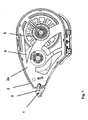
- the FIG. 1 shows a side view of an apparatus for transferring a film, in particular a correction film, from a carrier tape to a substrate.
- This device comprises a housing 2, which may consist essentially of two half shells and can be opened thereby.
- the half shells can be made for example of transparent plastic.
- a frame 2a is inserted or inserted, that can also be provided as a replaceable refill cartridge. From this frame 2a projecting an inventive order foot 1, which protrudes from the housing 2, even when inserted into the housing 2 frame 2a.
- scooter devices are known in principle, for example from the WO 02/083535 , When using such a device as a correction roller for applying a correction agent film on a substrate, however, the problems described above can occur.
- Thelethorfuß 1 is improved according to the invention in terms of what, but what from the side view of FIG. 1 is not recognizable.
- the FIG. 1 should therefore serve in particular for orientation as a schematic representation in the explanation of the invention.
- a supply reel 5 and a take-up reel 4 are used for a carrier tape 3, which are drivingly coupled together.
- the carrier tape is guided on its way from the supply reel 5 to the take-up reel 4 on the outside of the applicator foot 1.
- the carrier tape 3 still carries the applied film as a film on a substrate, while the back of thequestfuß 1 for take-up reel 4 strand strand of the carrier tape 3 no longer carries this agent, since this has already been delivered to a substrate is.
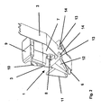
- FIG. 2 shows a perspective bottom view of thelethorfußes invention 1.
- the same components are denoted by the same reference numerals as in FIG. 1 ,
- the carrier tape 3 is in particular guided tightly over an application edge 6 of the applicator foot 1. This tightness is achieved by the drive-like coupling of the supply reel 5 and the take-up reel 4, in particular by a gear ratio of a transmission, which can not be explained in more detail here, which may in particular also include a slip clutch.
- the application foot according to the invention may preferably be manufactured as an injection molded part made of plastic.
- it comprises an intermediate piece 7 which connects the part of the application foot 1 carrying the application edge 6 to a bearing head 9 which can be inserted in a form-fitting manner into a corresponding receptacle of the frame 2 a.
- the intermediate piece 7 may be resiliently formed like a leaf spring, which can still be favored by a tapered taper 8.
- this is namely for applying the agent from the carrier tape 3 on a, for example, just resting on a table top sheet of paper, placed with the job foot 1 obliquely down on this sheet of paper and pressed with a certain pressure on the paper and then so far on the paper while maintaining this pressure, drawn according to the length of a film to be applied to the film section. Thereafter, the device is raised again, so that the film portion applied to the paper as possible tears off along the application edge 6, because it adheres to the paper, while the remaining on the carrier tape 3 there further adheres and thus lifted with the lifting of the device.
- the resilient compliance of the intermediate piece 7 is low, in particular, for example, to avoid damage to the orfußes 1 or to avoid tilting of the application edge 6.
- the elasticity of this intermediate piece 7 of the contact pressure moderately or to a certain extent controlled or controllable.
- the carrier tape 3 is guided around the application edge 6, wherein an upper spacer 10, upper, lateral guide cheeks 11 and lower lateral guide cheeks 12 are substantially involved.
- Abrissstegstummel 13 are arranged on the lower guide cheeks, which project toward one another.
- This Abrissstegstummel 13 form a kind of bridge on the underside of the bottom, the order edge 6 leading strand of the carrier tape 3.
- the Abrissstegstummel could be formed in principle as a continuous Abrisssteg and connected to each other. Then, however, the carrier tape 3 would have to be threaded through under this bridge as it was being mounted through an eyelet. In the formation of Abrissstegstummeln, as in the FIG. 2 instead, it is possible to feed the carrier tape 3 between the ends of the tear-off stubs 13. This threading is facilitated by chamfers 14 in the region of the ends of the Abragstegstummel 13.
- the Abrissstegstummel 13 together if necessary form a trailing edge for a film to be applied to a substrate.
- the film portion applied to the substrate should be neatly separated along the application edge 6 from the film still adhered to the carrier tape 3.
- it may still come to a certain extent to a detachment of the film from the carrier tape 3 at the lower run of the carrier tape.
- This area of the so-called Ablappens is then according to the invention to the distance delimited between the application edge 6 and the Abrissstegstummel 13, because at the latest at these Abrissstegstummeln the lapped portion of the film would tear off and would fall to the substrate. It then results at least at the level of Abrissstegstummel 13 a clean spoiler edge, so that at the lower run of the carrier tape 3 only a relatively short and limited film-free or medium-free section between the application edge 6 and Abrissstegstummeln 13 remains.
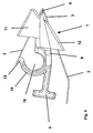
- FIG. 3 shows a front view of the order foot according to the invention FIG. 2 .
- the same reference numbers are again, as in the following figures, designated by the same reference numerals as in the FIGS. 1 and 2 ,
- the bearing head 9 is designed to be relatively elongated and from this perspective protrudes laterally beyond the guide cheeks 11 and 12 on one side.
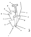
- FIGS. 4 and 5 show the two side views of themountedsfußes 1 according to the Figures 2 and 3 ,
- the bending of the spacer 10 encloses or at the same time forms a receiving sleeve 16 for a centering pin, which can be arranged on at least one of the housing shells of the housing 2 and when inserting the frame 2a in the housing 2 for an exact orientation and positioning of thelethorfußes 1 in the area the housing or from this outstanding, provides.
Landscapes
- Adhesive Tape Dispensing Devices (AREA)
Claims (36)
- Base d'application pour un appareil pour le transfert d'un film, en particulier d'un film de correction, d'une bande support à un substrat, de préférence sur du papier ou similaire,
sur lequel la bande support peut être déplacée au moyen de la base d'application pouvant être posée sur le substrat, la base d'application (1) comprenant une arête d'application (6) s'étendant principalement transversalement au sens de déplacement de la bande support (3),
caractérisée
en ce qu'une aide au déchirement pour le film à transférer est mise à disposition dans le sens contraire au sens de déplacement de la bande support (3) à une distance de l'arête d'application (6). - Base d'application selon la revendication 1,
caractérisée
en ce que l'aide au déchirement comprend essentiellement une arête de déchirement. - Base d'application selon la revendication 1,
caractérisée
en ce que l'arête de déchirement est disposée parallèlement à l'arête d'application (6). - Base d'application selon l'une des revendications précédentes,
caractérisée
en ce que l'aide au déchirement est conçue sous forme d'un étrier recouvrant la bande support (3) portant le film. - Base d'application selon l'une des revendications 2 à 4,
caractérisée
en ce que l'aide au déchirement présente une interruption pour l'enfilage de la bande support (3). - Base d'application selon la revendication 5,
caractérisée
en ce que l'interruption est disposée à peu près au centre dans l'aide au déchirement. - Base d'application selon la revendication 5 ou 6,
caractérisée
en ce que l'interruption est une fente agencée sensiblement à peu près dans le sens de déplacement de la bande support (3). - Base d'application selon l'une des revendications précédentes,
caractérisée
en ce qu'elle présente une surface de guidage et/ou de contact pouvant être tournée vers le substrat. - Base d'application selon la revendication 8,
caractérisée
en ce que des joues de guidage (12) à diriger de la surface de guidage et/ou de contact vers le substrat, qui font partie de l'aide au déchirement ou sur lesquelles l'aide au déchirement est disposée, dépassent. - Base d'application selon la revendication 9,
caractérisée
en ce qu'au moins une traverse de déchirement (13) commune, recouvrant la bande support (3), est disposée sur les joues de guidage (12) comme composant de l'aide au déchirement. - Base d'application selon la revendication 10,
caractérisée
en ce qu'à chaque fois un bout de la traverse de déchirement (13) est disposé sur chaque joue de guidage (12) et en ce que les bouts de la traverse de déchirement (13) doivent dépasser les uns sur les autres avec leurs extrémités libres et être dirigés les uns vers les autres, et qu'il reste alors un espace intermédiaire entre ces extrémités libres. - Base d'application selon la revendication 11,
caractérisée
en ce que les bouts de la traverse de déchirement (13) sont conçus sensiblement anguleux et présentent sur leur extrémité libre respective à chaque fois au moins sur une zone d'angle un angle neutralisé ou cassé par un chanfrein (14). - Base d'application selon la revendication 12,
caractérisée
en ce que le chanfrein (14) est disposé sur l'arête arrière externe, pouvant être tournée à chaque fois vers le substrat et tournée dans le sens contraire au sens de déplacement de la bande support (3), du bout concerné de la traverse de déchirement (13). - Base d'application selon l'une des revendications 9 à 13,
caractérisée
en ce que les joues de guidage (12) s'élargissent dans leur tracé depuis leur extrémité, tournée vers l'arête d'application (6), vers leur extrémité opposée à l'arête d'application (6) et dépassent en conséquence davantage de la surface de guidage et/ou la surface de contact. - Base d'application selon la revendication 14,
caractérisée
en ce que les joues de guidage (12) sont conçues essentiellement en forme de triangle. - Base d'application selon l'une des revendications précédentes,
caractérisée
en ce qu'elle présente dans une zone opposée à l'arête d'application (6) une tête de palier (9), qui peut être fixée par complémentarité de formes et être insérée dans un logement approprié d'un appareil pour le transfert d'un film. - Base d'application selon l'une des revendications précédentes,
caractérisée
en ce que la zone, comprenant l'arête d'application (6), est disposée sur une pièce intermédiaire (7) largement en forme de languette. - Base d'application selon la revendication 17,
caractérisée
en ce que la pièce intermédiaire (7) en forme de languette peut être déformée de façon élastique à la façon d'un ressort de lame. - Base d'application selon l'une des revendications 17 ou 18,
caractérisée
en ce que la pièce intermédiaire (7) en forme de languette est taillée dans au moins une partie pour son rétrécissement (8). - Base d'application selon l'une des revendications précédentes,
caractérisée
en ce que, vu à partir de l'arête d'application (6) dans le sens contraire au sens de déplacement de la bande support (3) et vu dans le sens de déplacement de la bande support, à chaque fois des joues de guidage (11, 12) et/ou des surfaces de guidage et/ou de contact pour la bande support (3) sont prévues dans le voisinage de l'arête d'application (6). - Base d'application selon l'une des revendications précédentes,
caractérisée
en ce qu'elle présente sur son côté opposé au substrat lors d'un transfert de film un écarteur (10), par lequel la bande support (3) va dans le sens de déplacement de la bande support (3), vu de l'arête d'application (6). - Base d'application selon la revendication 22,
caractérisée
en ce que l'écarteur (10) a un tracé d'arc. - Base d'application selon la revendication 22,
caractérisée
en ce que l'écarteur (10) présente sur l'extrémité libre de son coude une arête de guidage épaissie et/ou arrondie ou un bourrelet de guidage (15) pour la bande support (3). - Base d'application selon l'une des revendications précédentes,
caractérisée
en ce que l'arête d'application (6) est arrondie. - Base d'application selon l'une des revendications précédentes,
caractérisée
en ce que l'arête d'application (6) présente au moins une élévation pouvant être positionnée sur le substrat pour générer une pression de compression élevée. - Base d'application selon l'une des revendications précédentes,
caractérisée
en ce qu'elle est fabriquée tout ou partiellement en matière synthétique. - Base d'application selon la revendication 26,
caractérisée
en ce qu'elle est conçue sous forme d'une pièce intégrale moulée par injection en matière plastique. - Appareil pour le transfert d'un film, en particulier d'un film de correction, d'une bande support à un substrat, de préférence sur du papier ou similaire, sur lequel la bande support peut être déplacée au moyen de la base d'application pouvant être posée sur le substrat,
caractérisé par
une base d'application (1) selon une ou plusieurs des revendications précédentes. - Appareil selon la revendication 28,
caractérisé
en ce qu'il présente une bobine d'enroulement (4) et une bobine de déroulement (5) pour la bande support (3), la bande support (3) pouvant être déplacée depuis la bobine de déroulement (5) dans son sens de déplacement au moyen de l'arête d'application (6) vers la bobine d'enroulement (4). - Appareil selon la revendication 29,
caractérisé
en ce que la bobine d'enroulement (4) et la bobine de déroulement (5) sont couplées l'une à l'autre au moyen d'un accouplement, qui comprend un élément d'accouplement recevant la tension de la bande support (3) par l'arête d'application (6). - Appareil selon la revendication 30,
caractérisé
en ce que l'élément d'accouplement est un élément à accouplement glissant. - Appareil selon l'une des revendications 28 à 31,
caractérisé
en ce qu'il présente un boîtier (2) duquel au moins la partie, présentant l'arête d'application (6), de la base d'application (1) dépasse de façon librement accessible. - Appareil selon la revendication 32,
caractérisé
en ce que le boîtier (2) est constitué sensiblement de deux demi-coques à séparer l'une de l'autre. - Appareil selon l'une des revendications 29 à 33,
caractérisé
en ce qu'il comprend une unité de remplissage (2a) amovible, qui comprend pour sa part au moins la base d'application (1), la bobine d'enroulement (4), la bobine de déroulement (5) et l'accouplement. - Appareil selon la revendication 34,
caractérisé
en ce que l'unité de remplissage (2a) comprend également la bande support (3) prémontée. - Unité de remplissage pour un appareil pour le transfert d'un film, en particulier d'un film de correction, d'une bande de support à un substrat, de préférence à du papier ou similaire, sur lequel la bande support peut être déplacée au moyen de la base d'application pouvant être posée sur le substrat,
caractérisé par
les caractéristiques selon les revendications 34 ou 35.
Applications Claiming Priority (2)
| Application Number | Priority Date | Filing Date | Title |
|---|---|---|---|
| DE200410026720 DE102004026720A1 (de) | 2004-05-28 | 2004-05-28 | Auftragsfuß, Gerät und Nachfülleinheit zum Übertragen eines Filmes auf ein Substrat |
| PCT/EP2005/001542 WO2005118447A1 (fr) | 2004-05-28 | 2005-02-16 | Element d'application, appareil et unite de recharge pour le transfert d'un film sur un substrat |
Publications (2)
| Publication Number | Publication Date |
|---|---|
| EP1753684A1 EP1753684A1 (fr) | 2007-02-21 |
| EP1753684B1 true EP1753684B1 (fr) | 2012-10-10 |
Family
ID=34960410
Family Applications (1)
| Application Number | Title | Priority Date | Filing Date |
|---|---|---|---|
| EP05707419A Expired - Lifetime EP1753684B1 (fr) | 2004-05-28 | 2005-02-16 | Element d'application, appareil et unite de recharge pour le transfert d'un film sur un substrat |
Country Status (4)
| Country | Link |
|---|---|
| EP (1) | EP1753684B1 (fr) |
| DE (1) | DE102004026720A1 (fr) |
| ES (1) | ES2394212T3 (fr) |
| WO (1) | WO2005118447A1 (fr) |
Families Citing this family (6)
| Publication number | Priority date | Publication date | Assignee | Title |
|---|---|---|---|---|
| DE102007058031A1 (de) | 2007-11-30 | 2009-06-04 | Henkel Ag & Co. Kgaa | Gerät zum Übertragen eines Films von einem Trägerband auf ein Substrat |
| US8397784B2 (en) | 2010-08-31 | 2013-03-19 | Sanford, L.P. | Correction tape dispenser with variable clutch mechanism |
| US8746313B2 (en) | 2010-12-29 | 2014-06-10 | Sanford, L.P. | Correction tape re-tensioning mechanism and correction tape dispenser comprising same |
| US8578999B2 (en) | 2010-12-29 | 2013-11-12 | Sanford, L.P. | Variable clutch mechanism and correction tape dispenser with variable clutch mechanism |
| FR2981057B1 (fr) | 2011-10-10 | 2013-11-29 | Bic Soc | Dispositif manuel d'application par ruban d'un revetement sur un support a embout ameliore |
| US8746316B2 (en) | 2011-12-30 | 2014-06-10 | Sanford, L.P. | Variable clutch mechanism and correction tape dispenser with variable clutch mechanism |
Family Cites Families (3)
| Publication number | Priority date | Publication date | Assignee | Title |
|---|---|---|---|---|
| CH411621A (de) * | 1961-03-22 | 1966-04-15 | Heinrich Hermann Fa | Klebeeinrichtung mit Ausgabebehälter und doppelseitig mit Dauerklebstoff beschichtetem Klebeband |
| MXPA02008032A (es) * | 2000-02-25 | 2002-11-29 | Bic Deutschland Gmbh & Co | Dispositivo manual para transferir una pelicula, que tiene un elemento de aplicacion angular. |
| DE10118830B4 (de) * | 2001-04-17 | 2009-06-18 | Henkel Ag & Co. Kgaa | Kassettengerät |
-
2004
- 2004-05-28 DE DE200410026720 patent/DE102004026720A1/de not_active Withdrawn
-
2005
- 2005-02-16 EP EP05707419A patent/EP1753684B1/fr not_active Expired - Lifetime
- 2005-02-16 ES ES05707419T patent/ES2394212T3/es not_active Expired - Lifetime
- 2005-02-16 WO PCT/EP2005/001542 patent/WO2005118447A1/fr not_active Ceased
Also Published As
| Publication number | Publication date |
|---|---|
| EP1753684A1 (fr) | 2007-02-21 |
| DE102004026720A1 (de) | 2005-12-22 |
| WO2005118447A1 (fr) | 2005-12-15 |
| ES2394212T3 (es) | 2013-01-23 |
Similar Documents
| Publication | Publication Date | Title |
|---|---|---|
| EP0610590B1 (fr) | Dispositif pour poser un ruban adhésif sur le point de départ d'un rouleau | |
| DE69514679T2 (de) | Bandspender | |
| DE112012003066T5 (de) | Bandapplikator | |
| DE60101562T2 (de) | Spender mit einer förderspule | |
| DE102011054505A1 (de) | Kabelmarkierungsstreifen | |
| DE19841609A1 (de) | Haftelement oder -streifen für Fliegenden Rollenwechsel | |
| EP1753684B1 (fr) | Element d'application, appareil et unite de recharge pour le transfert d'un film sur un substrat | |
| DE19905547C2 (de) | Leiste, insbesondere Zierleiste für ein Kraftfahrzeug | |
| EP0322538A1 (fr) | Procédé et appareil pour enduire de colle des fils continus | |
| DE3104035C2 (de) | Gerät zum Bedrucken, Ausgeben und Anbringen von auf einem Trägerband haftenden Selbstklebeetiketten | |
| EP0034316B1 (fr) | Bande d'étiquettes | |
| EP1105331B1 (fr) | Appareil pour transferer sur un substrat une matiere appliquee sous forme d'un film sur une bande support | |
| DE10001465C2 (de) | Gerät zum Übertragen eines in Form eines Filmes auf ein Trägerband aufgebrachten Stoffes auf ein Substrat | |
| WO2013092607A1 (fr) | Rouleau destiné à une imprimante ainsi qu'imprimante équipée dudit rouleau | |
| WO2008003714A1 (fr) | Dispositif pour transférer un film d'un ruban support sur un substrat | |
| WO1992021568A1 (fr) | Procede et dispositif d'application sur un substrat d'une pellicule adhesive eventuellement enduite | |
| EP0994055A2 (fr) | Dispositif pour le transfert d'un matériaux de liaison double face | |
| DE10214604B4 (de) | Gerät zum Übertragen eines in Form eines Filmes auf ein Trägerband aufgebrachten Stoffes auf ein Substrat | |
| DE2626687C2 (de) | Handabroller, insbesondere für Klebeband und dergleichen | |
| DE4327544C1 (de) | Dosiersystem | |
| EP1071628A1 (fr) | Appareil pour transferer un film d'une bande support sur un substrat | |
| DE19909217A1 (de) | Klebeband-Übertragungsvorrichtung | |
| EP0972707A1 (fr) | Procédé et dispositif pour emballer un rouleau de matériau en bande | |
| EP0839665B1 (fr) | Cartouche à ruban avec moyens pour arrêter la fin du ruban | |
| DE102010007002A1 (de) | Bandschneider |
Legal Events
| Date | Code | Title | Description |
|---|---|---|---|
| PUAI | Public reference made under article 153(3) epc to a published international application that has entered the european phase |
Free format text: ORIGINAL CODE: 0009012 |
|
| 17P | Request for examination filed |
Effective date: 20061122 |
|
| AK | Designated contracting states |
Kind code of ref document: A1 Designated state(s): AT BE BG CH CY CZ DE DK EE ES FI FR GB GR HU IE IS IT LI LT LU MC NL PL PT RO SE SI SK TR |
|
| DAX | Request for extension of the european patent (deleted) | ||
| RAP1 | Party data changed (applicant data changed or rights of an application transferred) |
Owner name: HENKEL AG & CO. KGAA |
|
| GRAC | Information related to communication of intention to grant a patent modified |
Free format text: ORIGINAL CODE: EPIDOSCIGR1 |
|
| GRAP | Despatch of communication of intention to grant a patent |
Free format text: ORIGINAL CODE: EPIDOSNIGR1 |
|
| GRAC | Information related to communication of intention to grant a patent modified |
Free format text: ORIGINAL CODE: EPIDOSCIGR1 |
|
| GRAS | Grant fee paid |
Free format text: ORIGINAL CODE: EPIDOSNIGR3 |
|
| GRAA | (expected) grant |
Free format text: ORIGINAL CODE: 0009210 |
|
| AK | Designated contracting states |
Kind code of ref document: B1 Designated state(s): AT BE BG CH CY CZ DE DK EE ES FI FR GB GR HU IE IS IT LI LT LU MC NL PL PT RO SE SI SK TR |
|
| REG | Reference to a national code |
Ref country code: GB Ref legal event code: FG4D Free format text: NOT ENGLISH |
|
| REG | Reference to a national code |
Ref country code: CH Ref legal event code: EP Ref country code: AT Ref legal event code: REF Ref document number: 578869 Country of ref document: AT Kind code of ref document: T Effective date: 20121015 |
|
| REG | Reference to a national code |
Ref country code: IE Ref legal event code: FG4D Free format text: LANGUAGE OF EP DOCUMENT: GERMAN |
|
| REG | Reference to a national code |
Ref country code: DE Ref legal event code: R096 Ref document number: 502005013166 Country of ref document: DE Effective date: 20121206 |
|
| REG | Reference to a national code |
Ref country code: ES Ref legal event code: FG2A Ref document number: 2394212 Country of ref document: ES Kind code of ref document: T3 Effective date: 20130123 |
|
| PG25 | Lapsed in a contracting state [announced via postgrant information from national office to epo] |
Ref country code: SI Free format text: LAPSE BECAUSE OF FAILURE TO SUBMIT A TRANSLATION OF THE DESCRIPTION OR TO PAY THE FEE WITHIN THE PRESCRIBED TIME-LIMIT Effective date: 20121010 |
|
| REG | Reference to a national code |
Ref country code: NL Ref legal event code: VDEP Effective date: 20121010 |
|
| REG | Reference to a national code |
Ref country code: LT Ref legal event code: MG4D |
|
| PG25 | Lapsed in a contracting state [announced via postgrant information from national office to epo] |
Ref country code: IS Free format text: LAPSE BECAUSE OF FAILURE TO SUBMIT A TRANSLATION OF THE DESCRIPTION OR TO PAY THE FEE WITHIN THE PRESCRIBED TIME-LIMIT Effective date: 20130210 Ref country code: FI Free format text: LAPSE BECAUSE OF FAILURE TO SUBMIT A TRANSLATION OF THE DESCRIPTION OR TO PAY THE FEE WITHIN THE PRESCRIBED TIME-LIMIT Effective date: 20121010 Ref country code: LT Free format text: LAPSE BECAUSE OF FAILURE TO SUBMIT A TRANSLATION OF THE DESCRIPTION OR TO PAY THE FEE WITHIN THE PRESCRIBED TIME-LIMIT Effective date: 20121010 Ref country code: NL Free format text: LAPSE BECAUSE OF FAILURE TO SUBMIT A TRANSLATION OF THE DESCRIPTION OR TO PAY THE FEE WITHIN THE PRESCRIBED TIME-LIMIT Effective date: 20121010 Ref country code: SE Free format text: LAPSE BECAUSE OF FAILURE TO SUBMIT A TRANSLATION OF THE DESCRIPTION OR TO PAY THE FEE WITHIN THE PRESCRIBED TIME-LIMIT Effective date: 20121010 |
|
| PG25 | Lapsed in a contracting state [announced via postgrant information from national office to epo] |
Ref country code: PL Free format text: LAPSE BECAUSE OF FAILURE TO SUBMIT A TRANSLATION OF THE DESCRIPTION OR TO PAY THE FEE WITHIN THE PRESCRIBED TIME-LIMIT Effective date: 20121010 Ref country code: GR Free format text: LAPSE BECAUSE OF FAILURE TO SUBMIT A TRANSLATION OF THE DESCRIPTION OR TO PAY THE FEE WITHIN THE PRESCRIBED TIME-LIMIT Effective date: 20130111 Ref country code: CY Free format text: LAPSE BECAUSE OF FAILURE TO SUBMIT A TRANSLATION OF THE DESCRIPTION OR TO PAY THE FEE WITHIN THE PRESCRIBED TIME-LIMIT Effective date: 20121010 Ref country code: PT Free format text: LAPSE BECAUSE OF FAILURE TO SUBMIT A TRANSLATION OF THE DESCRIPTION OR TO PAY THE FEE WITHIN THE PRESCRIBED TIME-LIMIT Effective date: 20130211 |
|
| PG25 | Lapsed in a contracting state [announced via postgrant information from national office to epo] |
Ref country code: SK Free format text: LAPSE BECAUSE OF FAILURE TO SUBMIT A TRANSLATION OF THE DESCRIPTION OR TO PAY THE FEE WITHIN THE PRESCRIBED TIME-LIMIT Effective date: 20121010 Ref country code: EE Free format text: LAPSE BECAUSE OF FAILURE TO SUBMIT A TRANSLATION OF THE DESCRIPTION OR TO PAY THE FEE WITHIN THE PRESCRIBED TIME-LIMIT Effective date: 20121010 Ref country code: BG Free format text: LAPSE BECAUSE OF FAILURE TO SUBMIT A TRANSLATION OF THE DESCRIPTION OR TO PAY THE FEE WITHIN THE PRESCRIBED TIME-LIMIT Effective date: 20130110 Ref country code: DK Free format text: LAPSE BECAUSE OF FAILURE TO SUBMIT A TRANSLATION OF THE DESCRIPTION OR TO PAY THE FEE WITHIN THE PRESCRIBED TIME-LIMIT Effective date: 20121010 Ref country code: CZ Free format text: LAPSE BECAUSE OF FAILURE TO SUBMIT A TRANSLATION OF THE DESCRIPTION OR TO PAY THE FEE WITHIN THE PRESCRIBED TIME-LIMIT Effective date: 20121010 |
|
| PLBE | No opposition filed within time limit |
Free format text: ORIGINAL CODE: 0009261 |
|
| STAA | Information on the status of an ep patent application or granted ep patent |
Free format text: STATUS: NO OPPOSITION FILED WITHIN TIME LIMIT |
|
| PG25 | Lapsed in a contracting state [announced via postgrant information from national office to epo] |
Ref country code: RO Free format text: LAPSE BECAUSE OF FAILURE TO SUBMIT A TRANSLATION OF THE DESCRIPTION OR TO PAY THE FEE WITHIN THE PRESCRIBED TIME-LIMIT Effective date: 20121010 Ref country code: IT Free format text: LAPSE BECAUSE OF FAILURE TO SUBMIT A TRANSLATION OF THE DESCRIPTION OR TO PAY THE FEE WITHIN THE PRESCRIBED TIME-LIMIT Effective date: 20121010 |
|
| BERE | Be: lapsed |
Owner name: HENKEL A.G. & CO. KGAA Effective date: 20130228 |
|
| 26N | No opposition filed |
Effective date: 20130711 |
|
| PG25 | Lapsed in a contracting state [announced via postgrant information from national office to epo] |
Ref country code: MC Free format text: LAPSE BECAUSE OF NON-PAYMENT OF DUE FEES Effective date: 20130228 |
|
| REG | Reference to a national code |
Ref country code: CH Ref legal event code: PL |
|
| GBPC | Gb: european patent ceased through non-payment of renewal fee |
Effective date: 20130216 |
|
| PG25 | Lapsed in a contracting state [announced via postgrant information from national office to epo] |
Ref country code: CH Free format text: LAPSE BECAUSE OF NON-PAYMENT OF DUE FEES Effective date: 20130228 Ref country code: LI Free format text: LAPSE BECAUSE OF NON-PAYMENT OF DUE FEES Effective date: 20130228 |
|
| REG | Reference to a national code |
Ref country code: DE Ref legal event code: R097 Ref document number: 502005013166 Country of ref document: DE Effective date: 20130711 |
|
| REG | Reference to a national code |
Ref country code: IE Ref legal event code: MM4A |
|
| PG25 | Lapsed in a contracting state [announced via postgrant information from national office to epo] |
Ref country code: BE Free format text: LAPSE BECAUSE OF NON-PAYMENT OF DUE FEES Effective date: 20130228 Ref country code: GB Free format text: LAPSE BECAUSE OF NON-PAYMENT OF DUE FEES Effective date: 20130216 Ref country code: IE Free format text: LAPSE BECAUSE OF NON-PAYMENT OF DUE FEES Effective date: 20130216 |
|
| REG | Reference to a national code |
Ref country code: AT Ref legal event code: MM01 Ref document number: 578869 Country of ref document: AT Kind code of ref document: T Effective date: 20130216 |
|
| PG25 | Lapsed in a contracting state [announced via postgrant information from national office to epo] |
Ref country code: AT Free format text: LAPSE BECAUSE OF NON-PAYMENT OF DUE FEES Effective date: 20130216 |
|
| PG25 | Lapsed in a contracting state [announced via postgrant information from national office to epo] |
Ref country code: TR Free format text: LAPSE BECAUSE OF FAILURE TO SUBMIT A TRANSLATION OF THE DESCRIPTION OR TO PAY THE FEE WITHIN THE PRESCRIBED TIME-LIMIT Effective date: 20121010 |
|
| PG25 | Lapsed in a contracting state [announced via postgrant information from national office to epo] |
Ref country code: HU Free format text: LAPSE BECAUSE OF FAILURE TO SUBMIT A TRANSLATION OF THE DESCRIPTION OR TO PAY THE FEE WITHIN THE PRESCRIBED TIME-LIMIT; INVALID AB INITIO Effective date: 20050216 Ref country code: LU Free format text: LAPSE BECAUSE OF NON-PAYMENT OF DUE FEES Effective date: 20130216 |
|
| REG | Reference to a national code |
Ref country code: FR Ref legal event code: PLFP Year of fee payment: 12 |
|
| REG | Reference to a national code |
Ref country code: FR Ref legal event code: PLFP Year of fee payment: 13 |
|
| REG | Reference to a national code |
Ref country code: FR Ref legal event code: PLFP Year of fee payment: 14 |
|
| PGFP | Annual fee paid to national office [announced via postgrant information from national office to epo] |
Ref country code: ES Payment date: 20190320 Year of fee payment: 15 Ref country code: DE Payment date: 20190219 Year of fee payment: 15 |
|
| PGFP | Annual fee paid to national office [announced via postgrant information from national office to epo] |
Ref country code: FR Payment date: 20190220 Year of fee payment: 15 |
|
| REG | Reference to a national code |
Ref country code: DE Ref legal event code: R119 Ref document number: 502005013166 Country of ref document: DE |
|
| PG25 | Lapsed in a contracting state [announced via postgrant information from national office to epo] |
Ref country code: DE Free format text: LAPSE BECAUSE OF NON-PAYMENT OF DUE FEES Effective date: 20200901 Ref country code: FR Free format text: LAPSE BECAUSE OF NON-PAYMENT OF DUE FEES Effective date: 20200229 |
|
| REG | Reference to a national code |
Ref country code: ES Ref legal event code: FD2A Effective date: 20210706 |
|
| PG25 | Lapsed in a contracting state [announced via postgrant information from national office to epo] |
Ref country code: ES Free format text: LAPSE BECAUSE OF NON-PAYMENT OF DUE FEES Effective date: 20200217 |