EP1753284A1 - Part feeding head device and part mounting head device - Google Patents
Part feeding head device and part mounting head device Download PDFInfo
- Publication number
- EP1753284A1 EP1753284A1 EP05739239A EP05739239A EP1753284A1 EP 1753284 A1 EP1753284 A1 EP 1753284A1 EP 05739239 A EP05739239 A EP 05739239A EP 05739239 A EP05739239 A EP 05739239A EP 1753284 A1 EP1753284 A1 EP 1753284A1
- Authority
- EP
- European Patent Office
- Prior art keywords
- component
- suction
- head device
- distal end
- end surface
- Prior art date
- Legal status (The legal status is an assumption and is not a legal conclusion. Google has not performed a legal analysis and makes no representation as to the accuracy of the status listed.)
- Withdrawn
Links
Images


Classifications
-
- H—ELECTRICITY
- H05—ELECTRIC TECHNIQUES NOT OTHERWISE PROVIDED FOR
- H05K—PRINTED CIRCUITS; CASINGS OR CONSTRUCTIONAL DETAILS OF ELECTRIC APPARATUS; MANUFACTURE OF ASSEMBLAGES OF ELECTRICAL COMPONENTS
- H05K13/00—Apparatus or processes specially adapted for manufacturing or adjusting assemblages of electric components
- H05K13/04—Mounting of components, e.g. of leadless components
-
- H10P72/0446—
-
- H10P72/0442—
-
- H10P72/78—
-
- H10W72/0711—
-
- H10W72/07178—
-
- Y—GENERAL TAGGING OF NEW TECHNOLOGICAL DEVELOPMENTS; GENERAL TAGGING OF CROSS-SECTIONAL TECHNOLOGIES SPANNING OVER SEVERAL SECTIONS OF THE IPC; TECHNICAL SUBJECTS COVERED BY FORMER USPC CROSS-REFERENCE ART COLLECTIONS [XRACs] AND DIGESTS
- Y10—TECHNICAL SUBJECTS COVERED BY FORMER USPC
- Y10T—TECHNICAL SUBJECTS COVERED BY FORMER US CLASSIFICATION
- Y10T29/00—Metal working
- Y10T29/49—Method of mechanical manufacture
- Y10T29/49002—Electrical device making
- Y10T29/49117—Conductor or circuit manufacturing
- Y10T29/49124—On flat or curved insulated base, e.g., printed circuit, etc.
- Y10T29/49128—Assembling formed circuit to base
-
- Y—GENERAL TAGGING OF NEW TECHNOLOGICAL DEVELOPMENTS; GENERAL TAGGING OF CROSS-SECTIONAL TECHNOLOGIES SPANNING OVER SEVERAL SECTIONS OF THE IPC; TECHNICAL SUBJECTS COVERED BY FORMER USPC CROSS-REFERENCE ART COLLECTIONS [XRACs] AND DIGESTS
- Y10—TECHNICAL SUBJECTS COVERED BY FORMER USPC
- Y10T—TECHNICAL SUBJECTS COVERED BY FORMER US CLASSIFICATION
- Y10T29/00—Metal working
- Y10T29/49—Method of mechanical manufacture
- Y10T29/49002—Electrical device making
- Y10T29/49117—Conductor or circuit manufacturing
- Y10T29/49124—On flat or curved insulated base, e.g., printed circuit, etc.
- Y10T29/4913—Assembling to base an electrical component, e.g., capacitor, etc.
-
- Y—GENERAL TAGGING OF NEW TECHNOLOGICAL DEVELOPMENTS; GENERAL TAGGING OF CROSS-SECTIONAL TECHNOLOGIES SPANNING OVER SEVERAL SECTIONS OF THE IPC; TECHNICAL SUBJECTS COVERED BY FORMER USPC CROSS-REFERENCE ART COLLECTIONS [XRACs] AND DIGESTS
- Y10—TECHNICAL SUBJECTS COVERED BY FORMER USPC
- Y10T—TECHNICAL SUBJECTS COVERED BY FORMER US CLASSIFICATION
- Y10T29/00—Metal working
- Y10T29/53—Means to assemble or disassemble
- Y10T29/5313—Means to assemble electrical device
- Y10T29/53174—Means to fasten electrical component to wiring board, base, or substrate
- Y10T29/53178—Chip component
-
- Y—GENERAL TAGGING OF NEW TECHNOLOGICAL DEVELOPMENTS; GENERAL TAGGING OF CROSS-SECTIONAL TECHNOLOGIES SPANNING OVER SEVERAL SECTIONS OF THE IPC; TECHNICAL SUBJECTS COVERED BY FORMER USPC CROSS-REFERENCE ART COLLECTIONS [XRACs] AND DIGESTS
- Y10—TECHNICAL SUBJECTS COVERED BY FORMER USPC
- Y10T—TECHNICAL SUBJECTS COVERED BY FORMER US CLASSIFICATION
- Y10T29/00—Metal working
- Y10T29/53—Means to assemble or disassemble
- Y10T29/5313—Means to assemble electrical device
- Y10T29/53191—Means to apply vacuum directly to position or hold work part
Definitions
- the electronic component 1 has to be heated so as to obtain a uniform temperature distribution in the area of the mounting side surface 1a of the electronic component 1 where the bumps 2 are formed (joining area).
- the nonuniform temperature distribution in the joining area cases nonuniform heating of the plurality of bumps 2, resulting in that joining state of respective bumps 2 and substrate electrodes 220 corresponding thereto becomes random or nonuniform.
- joining defects occur between the electronic component 1 and substrate 219.
- the suction force from the suction hole 118c acts only upon a part of the joining area.
- the suction hole comprises a center section communicated with the suction passage and a plurality of branch sections extending radially from the center section.
- the shape of the suction hole increases uniformity of the suction force created by the negative pressure generated in the gap between the suction hole and the mounting side surface, thereby enhancing the accuracy of holding the component with the suction nozzle.
- the heat generated by the heater is uniformly transferred to the entire joining area of the component.
- the temperature distribution in the joining area becomes more uniform and the protruding electrodes are heated uniformly. Therefore, the plurality of protruding electrodes can be joined to the substrate electrodes in a uniform joining state.
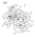
- Figs. 1 to 3 show an electronic component mounting device 11 according to an embodiment of the present invention which comprises a component supply head device and a component mounting head device.
- the lifter 17 of the component supply section 14 comprises a magazine 28 that can be moved upward and downward.
- the magazine 28 accommodates wafer supply plates 29 for supplying electronic components 12 in the form of wafers and tray supply plates 30 for supplying the electronic components 12 contained in trays 31 so that they can be selectively supplied.
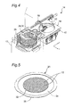
- the wafer supply plate 29 generally has a disk-like shape and comprises a wafer sheet 34 and wafer ring 35.
- the wafer sheet 34 is a stretchable sheet on which wafer 32 that have been subject to dicing.
- the wafer ring 35 holds the wafer sheet 34 in the vicinity of the outer peripheral edge thereof.
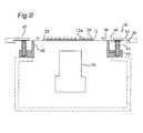
- the wafer supply plate 29 is sandwiched between distal end portions of the plate support pins 41 and the plate push sheets 42.
- the plate push sheets 42 are lowered by the cylinder 45 from the position shown in Fig. 8, the wafer sheet 34 will extend radially, with the distal end of the expand member 46 serving as a support point, as shown in Fig. 9.
- the tray supply plate 30 is held by the plate disposing device 19 in a similar manner.
- the plate disposing device 19 can be moved in the Y axis direction by the Y axis robot 48 having a driving motor 47.
- the electronic component 12 is pushed up from the lower surface side of the wafer sheet 34 by the ejecting pins 56 of the component ejecting device 20, whereby the electronic component 12 is peeled off from the wafer sheet 34 and held by the suction nozzle 65.
- the mounting head device 24 to which the electronic component 12 has been transferred moves above the substrate 13 on the XY table 25.
- the substrate 13 is aligned with respect to the electronic component 12 held by the suction nozzle 118 of the mounting head device 24 according to the recognition results by the recognition camera with two fields 26.
- the alignment is achieved by the movement of the substrate 13 in the X and Y axis directions performed by the XY table 25.
- the mounting head device 24 mounts the electronic component 12 onto the substrate 13. Similar operations are executed with respect to the tray supply plate 30.
- the outer dimensions of the distal end surface 65a of the suction nozzle 65 are set so that the outer peripheral edge of the distal end surface 65a is located outside the bump 39.
- the shapes of the suction nozzle 65 and suction hole 65b are not limited to those shown in Figs. 16A to 16C.
- eight branch sections 65e arranged with angular spaces of 45 degrees in the plan view or bottom view thereof can be provided.
- each straight line sections 139 extending beyond the outer circular section 140 to the peripheral edge side of the distal end surface 118a is communicated with the circular arc section 141.
- the suction nozzle 118 comprises four suction holes 118c each of which is communicated with the suction groove 126 in intersection positions of the straight line sections 139 and the inner circular section 140.
- suction grooves 126 communicated with the suction holes 118c are formed over the entire area corresponding to the joining area 127 of the electronic component 12 in the distal end surface 118a of the suction nozzle 118 of the component mounting head device 24. Therefore, the area of the non-mounting side surface 12b of the electronic component 12 corresponding to the joining area 127 is tightly sucked and held to the distal end surface 118a of the suction nozzle 118 with a high degree of flatness. As a result, the uniformity of temperature distribution in the joining area 127 is enhanced and the plurality of bumps 39 are heated uniformly. Therefore, the plurality of bumps 39 can be joined to the substrate electrodes 135 in a uniform joining state.
Landscapes
- Engineering & Computer Science (AREA)
- Manufacturing & Machinery (AREA)
- Microelectronics & Electronic Packaging (AREA)
- Supply And Installment Of Electrical Components (AREA)
- Wire Bonding (AREA)
- Manipulator (AREA)
Abstract
Description
- The present invention relates to a component supply head device for holding a component at a mounting side surface to be mounted on a substrate at a take-out position, moving to a transfer position, and transferring the component to a mounting head device at the transfer position after reversing an orientation of the mounting side surface. Further, the present invention relates to a component mounting head device for holding a component at a non-mounting surface opposite to a mounting side surface to be mounted on a substrate, mounting the mounting side surface onto the substrate.
- As disclosed in
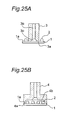
Patent Document 1, the above-described component supply head device comprises a suction nozzle for holding a component. The suction nozzle of the conventional component supply head device will be described with reference to Figs. 25A and 25B. As shown in Figs. 25A and 25B,bumps 2 are formed on amounting side surface 1a of anelectronic component 1. A suction nozzle shown 3 in Fig. 25A has a profile of adistal end surface 3a set smaller than a space between thebumps 2. Adistal end surface 3a of the suction nozzle 3 tightly contacts with an area of themounting side surface 1a where thebumps 2 are not arranged, and theelectronic component 1 is held at thedistal end surface 3a of the suction nozzle 3 by a suction force (negative pressure) of a vacuum source (not shown) acting on asuction hole 3c through asuction passage 3b. On the other hand, the suction nozzle 4 shown in Fig. 25B comprises apyramidal suction hole 4b on adistal end surface 4a, and walls of thesuction hole 4b contacts with a peripheral edge of theelectronic component 1. While themounting side surface 1a andbums 2 are not in direct contact with the walls of thesuction hole 4b, theelectronic component 1 is held at the distal end of the suction nozzle 4 by a suction force of a vacuum source (not shown). - However, in the suction nozzle 3 shown in Fig. 25A, deformation such as warping occurs in the
electronic component 1 under the effect of excess suction force acting on a portion (which is in contact with thedistal end surface 3a) of themounting side surface 1a, resulting in that an accuracy of holding theelectronic component 1 by the suction nozzle 3 is decreased. The low accuracy of holding the electronic component by the suction nozzle 3 decreases an accuracy of transferring theelectronic component 1 from the component supply head device to the mounting head device, thereby causing the decrease in the component mounting accuracy. Further, in the suction nozzle 4 shown in Fig. 25B, because the walls of thesuction hole 4b are brought into contact with the peripheral edge of theelectronic component 1, an outer size of thedistal end surface 4a has to be set larger than the outer size of theelectronic component 1. Thus, in case that theelectronic components 1 are supplied in a state of being accommodated in concave sections formed in a tray, thedistal end surface 4a of the suction nozzle 4 may interfere with the concave sections. This interference also decreases the accuracy of holding theelectronic component 1 by the suction nozzle 4. - As disclosed in
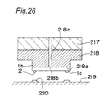
Patent Document 2, the above-described component mounting head device also comprises a suction nozzle for sucking and holding a component. An example of the suction nozzle of the conventional component mounting head device will be described below with reference to Fig. 26. Asuction hole 218b is formed in adistal end surface 218a of thesuction nozzle 218. Thedistal end surface 218a of thesuction nozzle 218 tightly contacts with a surface (non-mounting side surface 1b) opposite to amounting side surface 1a of theelectronic component 1, and theelectronic component 1 is held at thedistal end surface 218a of thesuction nozzle 218 by a suction force (static pressure) of a vacuum source (not shown) acting in thesuction hole 218b through asuction passage 218c. A temperature-adjustable heater 217 is attached to a rear side of thesuction nozzle 218. According to a flip chip method such as a solder bump local reflow, C4 (Controlled Collapse Chip Connection), joining using an ACF (Anisotropic Conductive Film), or joining using a NCP (Non Conductive Paste), theelectronic component 1 held by thesuction nozzle 218 is mounted ontosubstrate 219 generally by following process. First, thesuction nozzle 118 is moved above thesubstrate 219 and aligned with respect to thesubstrate 219 so thatsubstrate electrodes 220 formed on thesubstrate 219 and thebumps 2 of theelectronic component 1 correspond to each other. Then, thesuction nozzle 118 is lowered so that thebumps 2 are pressed against thesubstrate electrodes 220. Further, heat generated by theheater 117 is transferred to theelectronic component 1 through thesuction nozzle 118, thereby heating thebumps 2. Thebumps 2 andsubstrate electrodes 220 are joined by the pressing and heating, and theelectronic component 1 is mounted onto thesubstrate 219. - In the above-described mounting process, the
electronic component 1 has to be heated so as to obtain a uniform temperature distribution in the area of themounting side surface 1a of theelectronic component 1 where thebumps 2 are formed (joining area). The nonuniform temperature distribution in the joining area cases nonuniform heating of the plurality ofbumps 2, resulting in that joining state ofrespective bumps 2 andsubstrate electrodes 220 corresponding thereto becomes random or nonuniform. As a result, joining defects occur between theelectronic component 1 andsubstrate 219. In thesuction nozzle 118 shown in Fig. 26, the suction force from thesuction hole 118c acts only upon a part of the joining area. In other words, the entirenon-mounting surface 1b of theelectronic component 1 is not attached tightly and uniformly to thesuction nozzle 118. As a result, relatively large warping occurs in theelectronic component 1 held by thesuction nozzle 118. For example, in the case of an electronic component of square shape with a side of about 10 mm and a thickness of about 0.1 mm, the warping is about 14 µm. Because of the relatively large warping, the temperature distribution in the joining area becomes nonuniform, causing joining defects between theelectronic component 1 andsubstrate 219. - Patent Document 1:
Japanese Patent Application Laid-open Publication No.8-37395
Patent Document 2:Japanese Patent Application Laid-open Publication No.2003-297878 - It is an object of the present invention to provide a component supply head device capable of holding a component reliably and with high accuracy. It is another object of the present invention to provide a component mounting head device capable of heating the element so as to obtain a uniform temperature distribution in the joining area.
- A first invention relates to a component supply head device for holding a component at a mounting side surface with protruding electrodes to be mounted on a substrate, and reversing an orientation of the mounting side surface of the component to transfer the component to a component mounting head device so that the component mounting head device mounts the component onto the substrate. The component supply head device comprises a suction nozzle provided with a distal end surface where a suction hole is opened and a suction passage communicated with the suction hole at one end thereof. A portion of the distal end surface outside the suction hole abuts against the protruding electrode of the component. The suction hole is opposed with a gap to a portion of the mounding side surface on which the protruding electrodes are not provided. An air flow is generated by vacuum suction force acting from the other end of the suction passage, the air flow flowing from the gap between the suction hole and the mounting side surface into the suction passage through the suction hole and generating a negative pressure to hold the component at the distal end surface.
- The portion of the distal end surface of the suction nozzle outside the suction holes abuts against bumps, and the suction hole is opposed to the portion of mounting side surface on which the bumps do not exist. The air flow flowing into the suction passage from the gap through the suction hole is generated. The negative pressure (dynamic pressure) generated by the air flow holds the component at the suction nozzle. In other words, the suction nozzle of the component supply head device holds the component in a state where the distal end surface of the suction nozzle is not in contact with the mounting side surface. Therefore, a suction force uniformly acts upon the entire mounting side surface and the component can be held at the suction nozzle with a high accuracy, without causing deformation of the component, such as warping, by an excess suction force. As a result, the accuracy of transferring the component from the component supply head device to the mounting head unit can be enhanced.
- The suction hole comprises a center section communicated with the suction passage and a plurality of branch sections extending radially from the center section. The shape of the suction hole increases uniformity of the suction force created by the negative pressure generated in the gap between the suction hole and the mounting side surface, thereby enhancing the accuracy of holding the component with the suction nozzle.
- An outer dimension of the distal end surface is preferably set so that an outer peripheral edge of the distal end surface is positioned inside a peripheral edge of the component held by the suction nozzle and outside the protruding electrodes. Because the outer peripheral edge of the distal end surface of the suction nozzle is positioned on the inside of the peripheral edge of the component, when a component accommodated in a concave section of a tray is sucked and hold, the suction nozzle can be prevented from interfering with wall surfaces constituting the concave. Further, because the outer peripheral edge of the distal end surface of the suction nozzle is positioned outside the bumps, the bumps can be reliably abutted against the distal end surface in the portion outside the suction hole. Therefore, the component can be reliably held at the suction nozzle by the negative pressure generated in the gap between the suction hole and the mounting side surface.
- A second invention relates to a component mounting head device for holding a component at a non-mounting side surface opposite to a mounting side surface where a plurality of protruding electrodes are provided, and joining the protruding electrodes to corresponding substrate electrodes formed on a substrate to mount the component on the substrate. The component mounting head device comprises a heater for heating the component and a suction nozzle. The suction nozzle comprises a distal end surface where a suction hole is opened and a suction groove communicated with the suction hole is formed in an entire area corresponding to a joining area of the mounting side surface of the component where the protruding electrodes are provided, a proximal end surface opposite to the distal end surface abutting against the heater, and a suction passage communicated with the suction hole at one end thereof. The component is held at the distal end surface by a vacuum suction force acting from the other end of the suction passage.
- Because the suction groove connected to the suction hole is formed in the entire area corresponding to the joining area of the component, the entire area of the non-mounting side surface of the component corresponding to the joining area is tightly sucked and held to the distal end surface of the suction nozzle by the suction force acing in the suction hole and suction groove. In other words, the component is sucked and held by the suction nozzle in a state where the component has a high degree of flatness, and warping of the component is substantially reduced. For example, in the case of a component of square shape with a size of about 10 mm and a thickness of about 0.1 mm, the warping is only about 5 µm. Because the component is tightly sucked and held to the suction nozzle in a state where the component has a high degree of flatness, the heat generated by the heater is uniformly transferred to the entire joining area of the component. As a result, the temperature distribution in the joining area becomes more uniform and the protruding electrodes are heated uniformly. Therefore, the plurality of protruding electrodes can be joined to the substrate electrodes in a uniform joining state.
- The suction groove may be provided, in addition to the area corresponding to the joining area, outside the area corresponding to the joining area, that is, between the area and the peripheral edge of the suction nozzle.
- The arrangement, dimensions, and shape of the suction groove are set so that a non-mounting side surface of the component is sucked and held to the distal end surface of the suction nozzle with a high degree of flatness according to such factors as the shape, dimensions including thickness, and material of the component.
- The suction groove may be a combination of frame portions and lattice-like portions. More specifically, the suction groove comprises one closed pattern section disposed along the peripheral edge of the distal end surface, a plurality of first line sections disposed inside the closed pattern section so as to extend in a first direction and be communicated with the closed pattern section at both ends thereof, and a plurality of second line sections disposed inside the closed pattern to as to extend in a direction crossing the first direction and communicated with the first line sections intersecting therewith. The closed pattern section may be polygonal, e.g., quadrangular. Further, the closed pattern section may be in the form of a closed curve such as a circle or an ellipse. The first and second line sections may be straight lines, curved lines such as wavy lines, or polygonal lines.
- As an alternative, the suction groove as a whole may has a lattice-like shape. Specifically, the suction groove comprises a plurality of first line sections disposed so as to extend in a first direction, and a plurality of second sections disposed so as to extend in a second direction crossing the first direction and communicated with the first line sections intersecting therewith.
- As another alternative, the suction groove may comprise at least one closed pattern section disposed so as to surround a center of the area of the distal end surface corresponding to the joining area, and a plurality of line sections extending radially from the center of the area of the distal end surface corresponding to the joining area and communicated with the dosed pattern section intersecting therewith. As described above, the closed pattern section may be polygonal, e.g., quadrangular. Further, the closed pattern section may be in a form of a closed curve such as a circle or an ellipse. The first and second line sections may be straight lines, curved lines such as wavy lines, or polygonal lines.
- As yet another alternative, the suction groove has a form of a single continuous line. Specifically the suction groove may be in the form of a spiral line or may have a rectangular wave-like shape.
- The suction nozzle may comprise a recess formed in the distal end surface and separated from the suction hole. The recess is preferably disposed between the suction groove and the peripheral edge of the distal end surface. Even if the air is introduced from a very minute gap between the peripheral edge of the distal end surface of the suction nozzle and the electronic component sucked and held by the suction nozzle, the introduced air is heated while passing through the recess. As a result, the region of the distal end surface of the suction nozzle corresponding to the joining surface is prevented from being cooled by the air introduced from the gap. Therefore, providing the recess further improves the uniformity of temperature distribution in the joining area of the component held by the suction nozzle.
- According to the suction nozzle of the component supply head device of the first invention, the portion of the distal end surface outside the suction hole abuts against the bumps of the component, whereas the suction hole is opposed to the portion of the mounting side face of the component on which the protruding electrodes are not formed with the gap. This arrangement enables the suction nozzle to hold the component without causing deformation such as warping. Further, when the outer dimension of the distal end surface is set to that the outer peripheral edge of the distal end surface is positioned inside the peripheral edge of the component and outside the protruding electrodes, the distal end of the suction nozzle can be prevented from interfering with the wall surfaces constituting the concave of the tray in which the component is accommodated. Therefore, the holding accuracy of the component by the suction nozzle is increased and the accuracy of transferring the component to the mounting head device and the component mounting accuracy can be increased. Therefore, accuracy of holding the component by the suction nozzle is enhanced, resulting in that accuracies of transferring the component to the mounting head device and of mounting the component.
- According to the second invention, the suction groove connected to the suction hole is formed in the entire area corresponding to the joining area of the component in the distal end surface of the suction nozzle of the component mounting head device. This arrangement assures that the entire area of the non-mounting side surface of the component corresponding to the joining area is tightly sucked and held to the distal end surface of the suction nozzle and the component is sucked and held by the suction nozzle with high degree of flatness. This results in the uniform temperature distribution in the joining area of the component, casing the protruding electrodes are heated uniformly. Therefore, the plurality of protruding electrodes can be joined to the substrate electrodes in the uniform joining state.
-
- Fig. 1 is a perspective view illustrating a component mounting apparatus of an embodiment of the present invention;
- Fig. 2 is a schematic partial perspective view of the component mounting apparatus shown in Fig. 1;
- Fig. 3 is a schematic partial front view of the component mounting apparatus shown in Fig. 1;
- Fig. 4 is a semitransparent perspective view illustrating a component supply apparatus in the component mounting apparatus shown in Fig. 1;
- Fig. 5 is a perspective view illustrating a wafer supply plate;
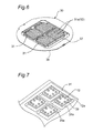
- Fig. 6 is a perspective view illustrating a tray supply plate;
- Fig. 7 is a partially enlarged perspective view of the tray shown in Fig. 6;
- Fig. 8 is a schematic cross-sectional view illustrating a plate disposing device in the component mounting apparatus shown in Fig. 1;
- Fig. 9 is a schematic cross-sectional view illustrating a plate disposing device in the component mounting apparatus shown in Fig. 1;
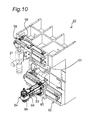
- Fig. 10 is a perspective view illustrating a component ejecting device in the component mounting apparatus shown in Fig. 1;
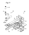
- Fig. 11 is an exploded perspective view illustrating the component ejecting device in the component mounting apparatus shown in Fig. 1;
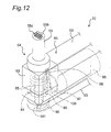
- Fig. 12 is a partial perspective view illustrating an ejecting head of the component ejecting device in the component mounting apparatus shown in Fig. 1;
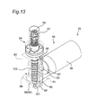
- Fig. 13 is a partial perspective view illustrating an internal structure of the ejecting head shown in Fig. 12;
- Fig. 14 is a schematic cross-sectional view illustrating the plate disposing device and component ejecting device in the component mounting apparatus shown in Fig. 1;
- Fig. 15 is a perspective view illustrating a reversing head device in the component mounting apparatus shown in Fig. 1;
- Fig. 16A is a schematic longitudinal sectional view of a suction nozzle in the reversing head device;
- Fig. 16B is a schematic bottom view of the suction nozzle shown in Fig. 16A;
- Fig. 16C is a schematic longitudinal sectional view illustrating a relationship between a concave of a tray and the suction nozzle shown in Fig. 16A;
- Fig. 17A is a schematic cross-sectional view of an alternative suction nozzle for the reversing head device;
- Fig. 17B is a schematic bottom view of the suction nozzle shown in Fig. 17A;
- Fig. 17C is a schematic longitudinal sectional view illustrating a relationship between the concave of the tray and the suction nozzle shown in Fig. 17A;
- Fig. 18 is a schematic front view of a component mounting head device;
- Fig. 19 is a schematic cross-sectional view of a suction nozzle in the component mounting head device;
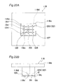
- Fig. 20A is a schematic bottom view of the suction nozzle shown in Fig. 19;
- Fig. 20B is a cross-sectional view along a line XX-XX in Fig. 20A;
- Fig. 20C is a schematic plan view of the suction nozzle shown in Fig. 19;
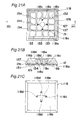
- Fig. 21A is a bottom view of a first alternative suction nozzle for the component mounting head device;
- Fig. 21B is a cross-sectional view along a line XXI-XXI in Fig. 21A;
- Fig. 21C is a schematic plan view of the suction nozzle shown in Fig. 21A;
- Fig. 22A is a schematic bottom view of a second alternative suction nozzle for the component mounting head device;
- Fig. 22B is a schematic side view of the suction nozzle shown in Fig. 22A;
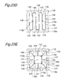
- Fig. 23A is a schematic bottom view of an alternative suction nozzle in the component mounting head device;
- Fig. 23B is a schematic bottom view of an alternative suction nozzle in the component mounting head device;
- Fig. 23C is a schematic bottom view of an alternative suction nozzle in the component mounting head device;
- Fig. 23D is a schematic bottom view of an alternative suction nozzle in the component mounting head device;
- Fig. 23E is a schematic bottom view of an alternative suction nozzle in the component mounting head device;
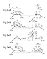
- Fig. 24A is a schematic explanatory drawing illustrating a relationship between the reversing head device and component mounting head device;
- Fig. 24B is a schematic explanatory drawing illustrating the relationship between the reversing head device and component mounting head device;
- Fig. 24C is a schematic explanatory drawing illustrating the relationship between the reversing head device and component mounting head device;
- Fig. 24D is a schematic explanatory drawing illustrating the relationship between the reversing head device and component mounting head device;
- Fig. 25A is a schematic cross-sectional view illustrating a suction nozzle of a conventional component supply head device;
- Fig. 25B is a schematic cross-sectional view illustrating a suction nozzle of a conventional component supply head device; and
- Fig. 26 is a schematic cross-sectional view illustrating a suction nozzle of the conventional component mounting head device.
-
- 11:
- electronic component mounting apparatus
- 12:
- electronic component
- 12a:
- mounting side surface
- 12b:
- non-mounting side surface
- 13:
- substrate
- 14:
- component supply section
- 15:
- mounting section
- 16:
- controller
- 17:
- lifter
- 18:
- plate translating device
- 19:
- plate disposing device
- 20:
- component ejecting device
- 22:
- reversing head device
- 24:
- component mounting head device
- 25:
- XY table
- 26:
- recognition camera with two fields
- 29:
- wafer supply plate
- 30:
- tray supply plate
- 31:
- tray
- 31a:
- concave
- 39:
- bump
- 65:
- suction nozzle
- 65b:
- suction hole
- 65c:
- suction passage
- 65d:
- center section
- 65e:
- branch section
- 111:
- base unit
- 112:
- holder
- 113:
- linear guide
- 114:
- linear motion guide
- 115:
- internal threaded section
- 116:
- rotary shaft mechanism
- 116a:
- suction passage
- 117:
- heater
- 1117a:
- suction passage
- 118:
- suction nozzle
- 118a:
- distal end surface
- 118b:
- proximal end surface
- 118c:
- suction hole
- 118d:
- suction passage
- 120,121:
- pulley
- 122:
- drive belt
- 125:
- vacuum pump
- 126:
- suction groove
- 127:
- joining area
- 131:
- rectangular section
- 132:
- lattice-shape section
- 133:
- longitudinal straight line section
- 134:
- lateral straight line section
- 135:
- substrate electrode
- 137:
- recess
- 138:
- center
- 139,143,144,145,146,147,149:
- straight line section
- 140:
- circular section
- 141:
- circular arc section
- 148:
- polygonal line section
- Figs. 1 to 3 show an electronic
component mounting device 11 according to an embodiment of the present invention which comprises a component supply head device and a component mounting head device. - An entire configuration and operation of the electronic
component mounting apparatus 11 will be described. The electroniccomponent mounting apparatus 11 is an apparatus for performing a mounting operation of mountingelectronic components 12 including chip components or bare IC chip as example of components onto asubstrate 13. The electronic component mounting apparatus generally comprises acomponent supply section 14 which is an example of a component supply apparatus for accommodating a plurality ofelectronic components 12 so that they can be supplied and a mountingsection 15 for performing a mounting operation of mounting theelectronic components 12 supplied from thecomponent supply section 14 on thesubstrate 13. Further, the electroniccomponent mounting apparatus 11 comprises a control unit orcontroller 16 for controlling the operation of thecomponent supply section 14 and mountingsection 15. - Referring to Fig. 4, the component supply section (component supply apparatus) 14 is provided with a lifter (component supplying and accommodating section) 17,
plate translating device 18, plate disposing device (component disposing unit) 19,component ejecting device 20,recognition camera 21, and a reversing head device (component supply head device) 22. On the other hand, the mountingsection 15 is provided with a component mountinghead device 24, an XY table (alignment device) 25, and a recognition camera with twofields 26. - Further, the
component supply section 14 will be described. Referring to Fig. 4, thelifter 17 of thecomponent supply section 14 comprises amagazine 28 that can be moved upward and downward. Themagazine 28 accommodateswafer supply plates 29 for supplyingelectronic components 12 in the form of wafers andtray supply plates 30 for supplying theelectronic components 12 contained intrays 31 so that they can be selectively supplied. As shown in Fig. 5, thewafer supply plate 29 generally has a disk-like shape and comprises awafer sheet 34 andwafer ring 35. Thewafer sheet 34 is a stretchable sheet on whichwafer 32 that have been subject to dicing. Thewafer ring 35 holds thewafer sheet 34 in the vicinity of the outer peripheral edge thereof. The arrangement of thewafer supply plate 29 allows that thewafer sheet 34 is radially extended so that lattice-like arranging positions of theelectronic components 12 can be radially extended, resulting in that the so-called "expand" can be conducted. On the other hand, as shown in Fig. 6, thetray supply plate 30 has an outer shape similar to that of thewafer supply plate 29 and comprises atray ring 36, atray placing section 37, and a plurality oftrays 31. Thetray ring 36 is an annular plate having an inner peripheral hole section of generally square shape. Thetray placing section 37 is attached to the inner peripheral hole section of thetray ring 36. Thetrays 31 are detachably placed on thetray placing section 37 for component supply. As enlargedly shown in Fig. 7,concave sections 31a for accommodating theelectronic components 12 are formed in thecomponent supply trays 31. - The
plate translating device 18 shown only in Fig. 4 can move in the Y axis direction and carries thewafer supply plate 29 ortray supply plate 30 that was taken out from themagazine 28 of thelifter 17 to theplate disposing device 19.
Both thewafer supply plate 29 andtray supply plate 30 are held by theplate disposing device 19 in a posture such that a mountingside surface 12a of theelectronic component 12 to thesubstrate 13, on which bumps (protruding electrodes) 39 are formed, is oriented vertically upward and that anon-mounting side surface 12b opposite to the mountingside surface 12a is vertically downward (See. Fig. 7). - Referring to Figs. 2, 4, 8, and 9, the
plate disposing device 19 comprises plate support pins 41 for supporting a lower surface of thewafer supply plate 29 ortray supply plate 30 andplate push sheets 42 positioned on upper surface sides of those plates. The plate support pins 41 can move in the direction perpendicular to anattachment member 43 having a ring-like shape in the plan view thereof.
Further, provided on the plate support pins 41 arecoil springs 44 elastically urging the support pins 41 vertically upward. On the other hand, theplate push sheets 42 can be moved upward and downward by acylinder 45. Further, an inner side of theattachment member 43 is provided with a cylindrical expandmember 46, a distal end of which abuts against a lower surface of thewafer sheet 34. As shown in Fig. 8, thewafer supply plate 29 is sandwiched between distal end portions of the plate support pins 41 and theplate push sheets 42. When theplate push sheets 42 are lowered by thecylinder 45 from the position shown in Fig. 8, thewafer sheet 34 will extend radially, with the distal end of the expandmember 46 serving as a support point, as shown in Fig. 9. As a result of this operation so-called "expand", spaces between adjacentelectronic components 12 are enlarged. Thetray supply plate 30 is held by theplate disposing device 19 in a similar manner. As clearly shown in Fig. 2, theplate disposing device 19 can be moved in the Y axis direction by theY axis robot 48 having a drivingmotor 47. - Referring to Figs. 2, and 10 to 14, the
component ejecting device 20 can be moved in the X axis direction by anX axis robot 52 having a drivingmotor 51. Further, thecomponent ejecting device 20 comprises an ejectinghead 54 at a distal end of anarm 53. Ejecting needles or Ejecting pins 56 are accommodated in aholder 55 of the ejectinghead 54 so that the ejecting pins 56 can be moved upward and downward. The ejecting pins 56 push up theelectronic components 12 adhered to thewafer sheet 34 from the lower surface of theelectronic components 12, thereby peeling theelectronic component 12 off thewafer sheet 34. Further, the ejectinghead 54 can be rotated about the Z axis. The structure and operation of thecomponent ejecting device 20 will be described latter in detail. - Referring to Figs. 1 and 2, an
X axis robot 59 with a drivingmotor 58 is equipped with arecognition camera 21, thus therecognition camera 21 being movable in the X axis direction. Therecognition camera 21 optically recognizes the position of theelectronic components 12 in thewafer supply plate 29 ortray supply plate 30 held in theplate disposing device 19. - Referring to Figs. 2 and 15, the reversing
head device 22 can be moved in the X axis direction by anX axis robot 62 having a drivingmotor 61. The reversinghead device 22 comprises asuction nozzle 65 for removably sucking and holding the mountingside surface 12a of theelectronic component 12 by a suction force of a vacuum pump 63 (see Fig. 16A). Thesuction nozzle 65 can be moved upward and downward and rotated about the Z axis. Further, an orientation in the vertical direction of thesuction nozzle 65 can be reversed. The structure and operation of the reversinghead device 22 will be described latter in detail. - Referring to Figs. 1, 2, and 18, the component mounting
head device 24 can be moved in the direction of X axis by anX axis robot 67 actuated by a drivingmotor 66. The component mountinghead device 24 comprises asuction nozzle 118 for removably sucking and holding thenon-mounting side surface 12b of theelectronic component 12 by a suction force of a vacuum pump 125 (see Fig. 19).
Thesuction nozzle 118 can be moved upward and downward and rotated about the Z axis. The structure and operation of the component mountinghead device 24 will be described below in detail. - Referring to Fig. 2, a substrate holder (substrate holding section) 72 for releasably holding and fixing the
substrate 13 is arranged on an upper surface of the XY table 25. This substrate holder stand 72 holds thesubstrate 13 that have been supplied from a substrate carrying device 73 (Fig. 1) that carries thesubstrate 13 leftward in the direction of X axis. The XY table 25 comprisesmotors substrate 13 held by thesubstrate holder 72 in the X and Y axis directions. This movement can align theelectronic component 12 held by the component mountinghead device 24 with respect to thesubstrate 13. - The
recognition camera 26 with two field fields (see Fig. 1) optically recognizes both theelectronic component 12 held by the component mountinghead device 24 and thesubstrate 13. - The overall operation of the
component supply section 14 and mountingsection 15 will be generally described below. Theplate translating device 18 takes thewafer supply plate 29 out of themagazine 28 of thelifter 17, moves the plate in the Y axis direction, and supplies it to theplate disposing device 19. After the holding of thewafer supply plate 29 by the plate disposing device 19 (Fig. 8) and the expand operation (Fig. 9) have been completed, the ejectinghead 54 is aligned with respect to any one of theelectronic components 12 according to the recognition results of therecognition camera 21. The alignment is achieved by the movement of theplate disposing device 19 in the Y axis direction performed by theY axis robot 48 and the movement of thecomponent ejecting device 20 in the X axis direction performed by theX axis robot 52. Further, the reversinghead device 22 is aligned with respect to the sameelectronic component 12 by the movement of the reversinghead device 22 in the X axis direction performed by theX axis robot 62. Synchronously with the suction operation performed by thesuction nozzle 65 of the reversinghead device 22, theelectronic component 12 is pushed up from the lower surface side of thewafer sheet 34 by the ejecting pins 56 of thecomponent ejecting device 20, whereby theelectronic component 12 is peeled off from thewafer sheet 34 and held by thesuction nozzle 65. - The reversing
head device 22 holding theelectronic component 12 with thesuction nozzle 65 moves in the X axis direction as far as a transfer position P2 (see Fig. 24) of theelectronic component 12 and reverses the orientation of thesuction nozzle 65. The component mountinghead device 24 is also moved in the X axis direction as far as the transfer position P2 by theX axis robot 67. After theelectronic component 12 has been sucked and held by thesuction nozzle 118 of the component mountinghead device 24, the suction by thesuction nozzle 65 of the reversinghead device 22 is released. As a result, theelectronic component 12 is transferred from the reversinghead device 22 to the mountinghead device 24. - The mounting
head device 24 to which theelectronic component 12 has been transferred moves above thesubstrate 13 on the XY table 25. Thesubstrate 13 is aligned with respect to theelectronic component 12 held by thesuction nozzle 118 of the mountinghead device 24 according to the recognition results by the recognition camera with twofields 26. The alignment is achieved by the movement of thesubstrate 13 in the X and Y axis directions performed by the XY table 25.
After this alignment, the mountinghead device 24 mounts theelectronic component 12 onto thesubstrate 13. Similar operations are executed with respect to thetray supply plate 30. - The
component ejecting device 20 will be described below in greater detail with reference to Figs. 1, 2, and 10 to 14. As shown in Figs. 2, 10, and 11, thecomponent ejecting device 20 comprises abase unit 80 installed on theX axis robot 52 having thedrive motor 51. A proximal end side of thearm 53 extending in the Y axis direction is connected to thebase unit 80. The proximal end side of thearm 53 is connected to thebase unit 80 through an LM guide orlinear motion guide 81 extending in the Z axis direction so that theentire arm 53 is moved upward and downward by acylinder 82 supported by thebase unit 80. - As shown in Figs. 12 to 14, the
arm 53 has at the distal end thereof the ejectinghead 54. As most clearly shown in Fig. 14, the ejectinghead 54 is positioned below thewafer supply plate 29 held by theplate disposing device 19.
The ejectinghead 54 has acasing 83 fixed to the distal end of thearm 53. Aball spline 84 is attached to thecasing 83 so that aspline shaft 85 of theball spline 84 extends in the vertical direction, and apin fixing member 87, to which proximal end sides of the plurality of ejectingpins 56 is fixed, is connected to a distal end side of thespline shaft 85. Arotation unit 86 of theball spline 84 is attached to the casing so as to be rotatable with respect to thecasing 83, and apulley 89 is fixed on the outer periphery thereof. As shown in Figs. 11 and 12, a drivingbelt 93 is arranged between thepulley 89 and apulley 92 fixed to an output shaft of amotor 91 disposed at the proximal end side of thearm 53. Therefore, the rotation of themotor 91 is converted into the rotation of thespline shaft 85 about the Z axis direction through thepulleys drive belt 93, androtation unit 86. - Referring to Figs. 12 and 13, the
component ejecting device 20 comprises alift driving mechanism 95 for moving thespline shaft 85 upward and downward. Specifically, acam follower 98 abutting against acam 97 fixed to the output shaft of themotor 96 is attached to an upper end of alever 99. Thelever 99 can be advanced in the vertical direction by anadvance guide 100 supported by thecasing 83. Further, aprotrusion 101 provided at an L-shaped lower end of thelever 99 abuts against a lower end of thespline shaft 85. Furthermore, acoil spring 102 is fitted onto thespline shaft 85. Thespline shaft 85 is elastically urged downward in the vertical direction by thecoil spring 102. As a result, the lower end of thespline shaft 85 constantly abuts against theprotrusion 101. The rotation of themotor 96 is converted into linear motion by thecam 97 andcam follower 98, and the linear motion is transmitted to thespline shaft 85 by thelever 99. - An upper end side of the
spline shaft 85 is inserted into ahollow holder 55 fixed to thecasing 83. As shown in Fig. 14, a distal end surface of theholder 55 abuts against the lower surface of thewafer sheet 34. Further, a plurality of sheet suction holes (not shown) are provided in the distal end surface of theholder 55, and the lower surface of thewafer sheet 34 is sucked to and held at thedistal end surface 55b of theholder 55 by the suction force of a vacuum pump 103 (shown only in Fig. 14) acting through the sheet suction holes. Thepin fixing member 87 is fixed to the upper end of thespline shaft 85 positioned inside theholder 55. The plurality of ejectingpins 56 are fixed to thepin fixing member 87. - The operation of the
component ejecting device 20 will be described below. As already described with reference to Figs. 8 and 9, the expand operation of thewafer sheet 34 is executed by theplate disposing device 19. Then, after thearm 53 is moved upward so that the distal end surface of theholder 55 is abutted against the lower surface of thewafer sheet 34, thevacuum pump 63 is actuated and the lower surface of thewafer sheet 34 is sucked and held to the sheet suction holes 55a (see Fig. 14). In case that the type ofelectronic components 12 is changed, the angular position of thepin fixing member 87 around the Z axis can be adjusted by rotating thespline shaft 85 by themotor 91, thereby the arrangement position in the plan view of the plurality of ejectingpins 56 can be adjusted according to the type of theelectronic components 12. Then, therecognition camera 21 recognizes the position of theelectronic component 12 which is to be ejected. The reversinghead device 22 moves according to the recognition results of therecognition camera 21, thesuction nozzle 65 is thereafter lowered and the suction of theelectronic component 12 is started. Synchronously with the upward movement of thesuction nozzle 65, the ejecting operation of theelectronic component 12 by the ejecting pins 56 is executed. Thesuction nozzle 65 moves upward as well as sucks and holds theelectronic component 12 peeled off from thewafer sheet 34 by the ejecting operation. - The reversing
head device 22 will be described below in detail. Referring to Figs. 2 and 15, the reversinghead device 22 comprises a reversinghead 103 having thesuction nozzle 65 for releasably sucking and holding theelectronic component 2 and arotation driving device 102 for rotating thesuction nozzle 65 about the Z axis. Further, thehead reversing device 22 comprises ahead lifting device 104 and a reversingdevice 105. Thehead reversing device 22 moves the reversinghead 103 upward and downward for achieving the upward and downward movement of thesuction nozzle 65. The reversingdevice 105 supports the reversinghead 103 movably upward and downward and rotates the reversinghead 103 about a reversing center extending along the Y axis direction for achieving reversing of the orientation of thesuction nozzle 65 in the vertical direction. Further, thereverse head device 22 comprises ahead frame 106 for supporting ahead lifting device 104 and reversingdevice 105. Thehead frame 106 is installed on theX axis robot 62 having thedriver motor 61. Therefore, thereverse head 103 moves back and forth in the X axis direction between a take-out position P1 of the electronic component 12 (see Fig. 24A) and the transfer position P2 of the electronic component 12 (see Fig. 24B). - Referring to Figs. 16A and 16B, the
suction nozzle 65 comprises asuction hole 65b opened at a flatdistal end surface 65a and asuction passage 65c communicated with thesuction hole 65b at one end thereof. Thevacuum pump 63 is connected to the other end of thesuction passage 65c. Thesuction hole 65b comprises acenter section 65d communicated with thesuction passage 65c and a plurality ofbranch sections 65e extending radially from thecenter section 65d. In the present embodiment, fourbranch sections 65e disposed with angular spaces of 90 degrees in the plan view or bottom view thereof are provided. The shape and size of thesuction hole 65b anddistal end surface 65a are set so that the portion of thedistal end surface 65a outside of thesuction hole 65b abuts against thebumps 39 of theelectronic component 12 and also so that thesuction hole 65b is opposed, with a gap, to a portion of the mountingside surface 12a on which thebumps 39 are not provided. For this reason, a suction operation of thevacuum pump 63 generates an air flow flowing from the gap between thedistal end surface 65 of thesuction nozzle 65 and the mountingside surface 12a into thesuction passage 65c through thesuction hole 65b. The negative pressure (dynamic pressure) generated by the air flow holds thecomponent 12 at thedistal end surface 65a In other words, thedistal end surface 65a of thesuction nozzle 65 of the reversinghead device 22 sucks and holds theelectronic component 12 in a state where thedistal end surface 65a is not in contact with the mountingside surface 12a. Therefore, the suction force uniformly acts onto the entire mountingside surface 12a and theelectronic component 12 can be held on thesuction nozzle 65 with high accuracy, without causing deformation, such as warping, by an excess suction force. - Further, as shown by a reference symbol t1 in Fig. 16A, the outer dimensions of the
distal end surface 65a of thesuction nozzle 65 are set so that the outer peripheral edge of thedistal end surface 65a is positioned inside the peripheral edge of theelectronic component 12 for example by 25-50 µm. Therefore, as shown in Fig. 16C, even when theelectronic component 12 accommodated in theconcave section 31a of thetray 31 abuts against a wall surface constituting theconcave section 31a, a gap of about 25-50 µm shown by a reference symbol t2 is ensured between thedistal end surface 65a of thesuction nozzle 65 and the wall surface of theconcave section 31a, and thesuction nozzle 65 can be prevented from interfering with the wall surface of theconcave section 31a Further, the outer dimensions of thedistal end surface 65a of thesuction nozzle 65 are set so that the outer peripheral edge of thedistal end surface 65a is located outside thebump 39. Therefore, because thebump 39 can be reliably abutted against thedistal end surface 65a in the portion outside thesuction hole 65b, theelectronic component 12 can be reliably held at thesuction nozzle 65 by the negative pressure generated in the aforementioned gap between thesuction hole 65b and mountingside surface 12a - The shapes of the
suction nozzle 65 andsuction hole 65b are not limited to those shown in Figs. 16A to 16C. For example, as shown in Fig. 17A through Fig. 17C, eightbranch sections 65e arranged with angular spaces of 45 degrees in the plan view or bottom view thereof can be provided. - The component mounting
head device 24 will be described below in detail. Referring to Figs. 1, 2, and 18, the component mountinghead device 24 comprises abase unit 111 installed on theX axis robot 67 actuated by themotor 66 and can move along the X axis direction. Aholder 112 is attached to thebase unit 111. Theholder 112 can move in the vertical direction with respect to thebase unit 111 by alinear guide 113. A ball threadedshaft 114 extending in the vertical direction is rotatably supported by thebase unit 111. An internal threadedsection 115 fixed to theholder 112 is engaged to the ball threadedshaft 114. when the ball threadedshaft 114 is rotated by amotor 68, theholder 112 is moved upward or downward according to a rotation direction thereof. - A
rotary shaft mechanism 116 extending in the vertical direction is rotatably supported by theholder 112. Aheater 117 for heating theelectronic component 12 is fixed to a lower end side of therotary shaft mechanism 116. Further, thesuction nozzle 118 is attached in a replaceable manner to a lower side of theheater 117. In the present embodiment, theheater 117 is a pulse ceramic heater as a surface heater. However, the type of the heater is not specifically limited as long as it is adapted to heat theelectronic component 12 held by thesuction nozzle 118. - A
pulley 120 is fixed to an upper end side of therotary shaft mechanism 116. Amotor 69 is fixed to theholder 112 so that the output shaft of themotor 69 is oriented vertically upward. Apulley 121 is fixed to an output shaft of themotor 69. A drive belt 122 is arranged between thepulleys motor 69 is transmitted to therotary shaft mechanism 116 through thepulleys - Referring to Figs. 19 to 20C, the
suction nozzle 118 comprises a flatdistal end section 118a for sucking and holding thenon-mounting side surface 12b of theelectronic component 12 and aproximal end surface 118b opposite to thedistal end surface 118a and abutting against theheater 117. - Four
suction holes 118c are opened in thedistal end surface 118a. Foursuction passages 118d each of which is communicated withrespective suction holes 118c at one end thereof are formed in thesuction nozzle 118. The other ends of thesuction passages 118d are communicated with across-shaped aggregation groove 118e formed in theproximal end surface 118b. Asuction passage 117a communicated with theaggregation groove 118e at one end thereof is formed in theheater 117. The other end of thesuction passage 117a is connected to the vacuum pump 125 (shown only in Fig. 19) through asuction passage 116a formed in therotary shaft mechanism 116. Therefore, the suction holes 118c are communicated with thevacuum pump 125 through thesuction passages - Further, a
suction groove 126 communicated with thesuction passage 118c are formed in thedistal end surface 118a As shown in Fig. 20A, in thedistal end surface 118a of the suction nozzle, thesuction grooves 126 are formed so as to extend in an entire area corresponding to the area of the mountingside surface 12a of theelectronic component 12 where thebump 39 was formed (joining area 127). Furthermore, thesuction grooves 126 are formed with a uniform pitch in the area of thedistal end surface 118a corresponding to the joiningarea 127. - In the present embodiment, the
suction groove 126 comprises one rectangular section (closed pattern section) 131 and a lattice-shapedsection 132 disposed inside therectangular section 131. Therectangular section 131 is formed along the peripheral edge of thedistal end surface 118a The lattice-shapedsection 132 comprises three longitudinalstraight line sections 133 and three lateralstraight line sections 134. The longitudinalstraight line sections 133 are disposed so as to extend in the up-down direction in Fig. 20A, and are parallel to each other. Both ends of each longitudinalstraight line section 133 are communicated with therectangular section 131. The lateralstraight line sections 134 are disposed so as to extend in the left-right direction in Fig. 20A, that is, in the direction perpendicular to the longitudinalstraight line sections 133, and are parallel to each other. Similarly to the longitudinalstraight line sections 133, both ends of the lateralstraight line sections 134 are communicated with therectangular section 131. Further, each lateralstraight line section 134 is communicated with the intersecting longitudinalstraight line section 133. Twosuction holes 118c are opened in the longitudinalstraight line section 133 located in the center. Further, twosuction holes 118c are opened in the lateralstraight line section 134 located in the center. - The
electronic component 12 is sucked and held by thesuction nozzle 118 at thenon-mounting side surface 12b. A suction force (negative pressure) of thevacuum pump 125 is transferred to the suction holes 118c andsuction grooves 126 through thesuction passages non-mounting side surface 12b of theelectronic component 12 from both the suction holes 118c and thesuction grooves 126. Because the suction force acts on thenon-mounting side surface 12b of theelectronic component 12 not only from the suction holes 118c, but also from thesuction grooves 126, the entire area of thenon-mounting side surface 12b corresponding to the joiningarea 127 is tightly sucked and held to thedistal end surface 118a of thesuction nozzle 118. In other words, theelectronic component 12 is sucked and held to thesuction nozzle 118 in a state with a high degree of flatness and warping of theelectronic component 12 is substantially reduced. Because theelectronic component 12 is tightly sucked and held to thesuction nozzle 118 with a high degree of flatness, the heat generated by theheater 117 is uniformly transmitted to the entire joiningarea 127 of theelectronic component 12. As a result, the uniformity of temperature distribution in the joiningarea 127 enhanced, casing that the plurality ofbumps 39 are heated uniformly. Therefore, the plurality ofbumps 39 can be joined to thesubstrate electrodes 135 in a uniform joining state. - In order for the
suction nozzle 118 to suck and hold theelectronic component 12 tightly and with the high degree of flatness, it is preferred that thesuction grooves 126 be densely and uniformly disposed at least in the enter region of thedistal end surface 118a corresponding the joiningarea 127. Referring to Fig. 20A, it is preferred that a width "w" and pitch "p" of thesuction groove 126 is smaller and that that a large number of grooves is present in the joiningarea 127. For example, in case that anelectronic component 12 in the form of a square with a side of about 10 mm and a thickness of about 0.1 mm is sucked and held by the suction nozzle having thesuction groove 126 the width "w" set at 0.2 mm and the pitch "p" set at 1 mm, the warping of theelectronic component 12 is reduced to about 5 µm. - Figs. 21A to Fig. 21C illustrate a first alternative of the
suction nozzle 118 of the component mountinghead device 24. Arectangular recess 137 is formed in thedistal end surface 118a of thesuction nozzle 118 between therectangular section 131 of thesuction groove 126 and the peripheral edge of thedistal end surface 118a Unlike thesuction groove 126, thisrecess 137 is not communicated with the suction holes 118c and is not affected by the suction force of thevacuum pump 125. - Even if the air is introduced from a very minute gap between the peripheral edge of the
distal end surface 118a of thesuction nozzle 118 and theelectronic component 12 sucked and held by thesuction nozzle 118, the introduced air is heated while passing through therecess 137 and then passes to the center area of thedistal end surface 118a As a result, the region of thedistal end surface 118a of thesuction nozzle 118 corresponding to the joiningsurface 127 is prevented from being cooled by the air introduced from the gap. Therefore, providing therecess 137 in addition to thesuction grooves 126 in thedistal end surface 118a further improves the uniformity of temperature distribution in the joiningarea 127 of theelectronic component 12 held by thesuction nozzle 118. Other structures and operations of the alternative shown in Figs. 21A to Fig. 21C are identical to those of thesuction nozzle 118 shown in Figs. 19 to 20C. - Figs. 22A to Fig. 22C illustrate a second alternative of the
suction nozzle 118 of the component mountinghead device 24. In this alternative, thesuction groove 126 formed in thedistal end surface 118a of thesuction nozzle 118 comprises the lattice-shaped section including three longitudinalstraight line sections 133 and three lateralstraight line sections 134, but has no rectangular section 131 (see Fig. 20A). Further, thesuction nozzle 118 is formed with onesuction hole 118c communicated with a center portion of the lattice-shapedsection 132 at one end thereof. - Figs. 23A to Figs. 23E illustrate other various alternatives of the
suction nozzle 118. In the alternative suction nozzle shown in Fig. 23A, thesuction groove 126 comprises threerectangular sections 131 disposed concentrically so as to surround acenter 138 of the area of thedistal end surface 118a corresponding to the joiningarea 127. Further, thesuction groove 126 comprises fourstraight line sections 139 extending radially from thecenter 138 of the area of thedistal end surface 118a corresponding to the joiningarea 127. Eachstraight line sections 139 is communicated with therectangular section 131 at an inner side at one end thereof as well as therectangular section 131 at an outer side at the other end thereof. Furthermore, thestraight line sections 139 cross the rectangular frame-shapedsection 131 at an intermediate position. Thesuction nozzle 118 comprises foursuction holes 118c each of which is communicated with thesuction groove 126 in intersection positions of thestraight line sections 139 and the innerrectangular section 131. - In the alternative shown in Fig. 23B, the
suction groove 126 comprises threecircular sections 140 disposed concentrically so as to surround thecenter 138 of the area corresponding to the joiningarea 127. Further, thesuction groove 126 comprises fourstraight line sections 139 extending radially from thecenter 138. Eachstraight line section 139 is communicated with thecircular section 140 at an inner side. Further, eachstraight line section 139 crosses thecircular sections 140 at an intermediate position and an outer side and is communicated with thereto. Thesuction groove 126 comprises fourcircular arc sections 141 between the outercircular section 140 and the peripheral edge of thedistal end surface 118a. The other end of eachstraight line sections 139 extending beyond the outercircular section 140 to the peripheral edge side of thedistal end surface 118a is communicated with thecircular arc section 141. Thesuction nozzle 118 comprises foursuction holes 118c each of which is communicated with thesuction groove 126 in intersection positions of thestraight line sections 139 and the innercircular section 140. - In the alternative shown in Fig. 23C, the
suction groove 126 has a single line-like shape. Specifically, thesuction groove 126 has a spiral shape formed by connecting together a plurality ofstraight line sections 143 extending parallel to lateral sides in Fig. 23C of four sides defining the peripheral edge of thedistal end surface 118a of thesuction nozzle 118 and a plurality ofstraight line sections 144 extending parallel to longitudinal sides of the peripheral edge of thedistal end surface 118a. Thesuction nozzle 118 comprises twosuction holes 118c. One ofsuction holes 118c is communicated with thesuction groove 126 in the inner end section of the suction groove, and theother suction hole 118c is communicated with thesuction groove 126 between the inner end section and an outer end section of thesuction groove 126. - The
alternative suction groove 126 shown in Fig. 23D also has a single line-like shape. Specifically, thesuction groove 126 has a rectangular wave-like shape formed by connecting a plurality ofstraight line sections 145 extending parallel to lateral sides of thedistal end surface 118a of thesuction nozzle 118 and a plurality ofstraight line sections 146 extending parallel to longitudinal sides. Thesuction nozzle 118 comprises twosuction holes 118c that are communicated with thesuction groove 126 at the longitudinalstraight line sections 146. - In the alternative shown in Fig. 23E, the
suction groove 126 comprises onerectangular section 131 surrounding thecenter 138 of the area of thedistal end surface 118a corresponding to the joiningarea 127. Furthe, thesuction groove 126 comprises fourstraight line sections 147 and fourpolygonal line sections 148 between therectangular section 131 and the peripheral edge of thedistal end surface 118a. Thosestraight line sections 147 andpolygonal line sections 148 are disposed on a virtual rectangle concentric with therectangular section 131 and larger in size than therectangular section 131. Further, thesuction groove 126 comprises eightstraight line sections 149 extending radially with respect to thecenter 138. One end of eachstraight line section 149 is communicated with therectangular section 131 and the other end is communicated with thestraight line sections 147 orpolygonal line sections 148. Thesuction nozzle 118 comprises foursuction holes 118c that are communicated with thesuction groove 126 at corners of therectangular section 131. - The shape, size, number, and arrangement position of the suction hole, suction grooves and recesses formed in the distal end surface of the
suction nozzle 118 of the component mountinghead device 24 are not limited to the above-described examples and can be easily set according to the size, and shape of theelectronic components 12 and the number ofbumps 39 so that the area of thenon-mounting side surface 12b of theelectronic component 12 corresponding to the joiningarea 127 is brought into tight contact with thedistal end surface 118a of thesuction nozzle 118. - Referring to Figs. 24A to 24D, the operations of taking the
electronic component 12 out of theplate disposing device 19 by the reversinghead device 22 and mounting on thesubstrate 13 by the mountinghead device 24 will be described below. First, as shown in Fig. 24A, at the supply position P1 of theelectronic component 12 corresponding to theplate disposing device 19, thesuction nozzle 65 of the reversinghead device 22 sucks and holds theelectronic component 12 from thewafer supply plate 29 ortray supply plate 30. At this operation thesuction nozzle 65 holds the mountingside surface 12a of theelectronic component 12 oriented upward in the vertical direction. - As shown in Fig. 24B, the
suction nozzle 65 rises and the mountinghead device 24 moves to the transfer position P2. Then, the reversinghead device 22 holding theelectronic component 12 by thesuction nozzle 65 moves to the transfer position P2 and is positioned below the mountinghead device 24. The orientation of thereverse head 103 is then reversed. As a result, thenon-mounting side surface 12b of theelectronic component 12 opposite to the mountingside surface 12a is oriented upward in the vertical direction. Then, as shown in Fig. 24C, thesuction nozzle 118 of the mountinghead device 24 is lowered so as to suck and hold theelectronic component 12. Theelectronic component 12 is held by the holdingsection 70 in a posture where the mountingside surface 12a faces down in the vertical direction (posture in which thenon-mounting side surface 12b faces up in the vertical direction). - As shown in Fig. 24D, the mounting
head device 24 moves above thesubstrate 13 and theelectronic component 12 is aligned with respect to thesubstrate 13 so that thesubstrate electrodes 135 and bumps 39 are corresponded to each other. Then, thesuction nozzle 118 is lowered so that thebumps 39 are pressed against thesubstrate electrodes 135. Further, theelectronic component 12 is heated by theheater 117. Thebump 39 andsubstrate electrode 135 are joined by the pressing and heating, and theelectronic component 12 is mounted onto thesubstrate 13. - As described, the
suction nozzle 65 of the reversinghead device 22 holds theelectronic component 12 in the state where thedistal end surface 65a of the suction nozzle is not in contact with the mountingside surface 12a Therefore, the suction force acts uniformly on the entire mountingside surface 12a and theelectronic component 12 can be held by thesuction nozzle 65 with high accuracy, without causing deformation such as warping due to the excess suction force. As a result, the accuracy of transferring the component from the reversinghead device 22 to the component mountinghead device 24 is enhanced. Further,suction grooves 126 communicated with the suction holes 118c are formed over the entire area corresponding to the joiningarea 127 of theelectronic component 12 in thedistal end surface 118a of thesuction nozzle 118 of the component mountinghead device 24. Therefore, the area of thenon-mounting side surface 12b of theelectronic component 12 corresponding to the joiningarea 127 is tightly sucked and held to thedistal end surface 118a of thesuction nozzle 118 with a high degree of flatness. As a result, the uniformity of temperature distribution in the joiningarea 127 is enhanced and the plurality ofbumps 39 are heated uniformly. Therefore, the plurality ofbumps 39 can be joined to thesubstrate electrodes 135 in a uniform joining state. - Although the present invention has been fully described with reference to the accompanying drawings, various changes and modifications will be apparent to those skilled in the art. Therefore, such changes and modifications should be construed as included in the present invention, unless they depart from the scope and spirit of the present invention.
Claims (17)
- A component supply head device (22) for holding a component (12) at a mounting side surface (12a) with protruding electrodes (39) to be mounted on a substrate (13), and reversing an orientation of the mounting side surface of the component to transfer the component to a component mounting head device (24) so that the component mounting head device mounts the component onto the substrate, comprising:a suction nozzle (65) provided with a distal end surface (65a) where a suction hole (65b) is opened and a suction passage (65c) communicated with the suction hole at one end thereof, wherein a portion of the distal end surface outside the suction hole abuts against the protruding electrodes of the component, wherein the suction holes is opposed with a gap to a portion of the mounding side surface on which the protruding electrodes are not provided, and wherein an air flow is generated by vacuum suction force acting from the other end of the suction passage, the air flow flowing from the gap between the suction hole and the mounting side surface into the suction passage through the suction hole and generating a negative pressure to hold the component at the distal end surface.
- The component supply head device according to claim 1, wherein the suction hole comprises a center section (65d) communicated with the suction passage and a plurality of branch sections (65d, 65e) extending radially from the center section.
- The component supply head device according to claim 1 or 2, wherein an outer dimension of the distal end surface is set so that an outer peripheral edge of the distal end surface is positioned inside a peripheral edge of the component held by the suction nozzle and outside the protruding electrodes.
- A component supply apparatus, comprising:the component supply head device (22) according to claim 1;a component disposing section (19) where a plurality of components are disposed so that they can be taken out by the suction nozzle; anda component supply and accommodation section for accommodating the components so that they can be disposed in the component disposing section.
- A component mounting apparatus, comprising:the component supply apparatus according to claim 4;the component mounting head device (24) for releasably holding the component;a substrate holding section (72) for releasably holding the substrate; anda alignment device (25) for aligning the substrate held by the substrate holding section and the component held by the component mounting head device.
- A component mounting head device (24) for holding a component (12) at a non-mounting side surface (12b) opposite to a mounting side surface (12a) where a plurality of protruding electrodes (39) are provided, and joining the protruding electrodes to corresponding substrate electrodes (135) formed on a substrate (13) to mount the component on the substrate, comprisinga heater (117) for heating the component; anda suction nozzle (118) comprising a distal end surface (118a) where a suction hole (118c) is opened and a suction groove (126) communicated with the suction hole is formed in an entire area corresponding to a joining area (127) of the mounting side surface of the component where the protruding electrodes are provided, a proximal end surface (118b) opposite to the distal end surface abutting against the heater, and a suction passage (118d) communicated with the suction hole at one end thereof, wherein the component is held at the distal end surface by a vacuum suction force acting from the other end of the suction passage.
- The component mounting head device according to claim 6, wherein the suction groove comprises:a closed pattern section (131) disposed along a peripheral edge of the distal end surface;a plurality of first line sections (133) disposed inside the closed pattern section so as to extend in a first direction and communicated with the closed pattern section at both ends thereof; anda plurality of second line sections (134) disposed inside the closed pattern so as to extend in a direction crossing the first direction, communicated with the closed pattern section at both ends thereof, and communicated with the first line sections intersecting therewith.
- The component mounting head device according to claim 6, wherein the suction groove comprises:a plurality of first line sections (133) disposed so as to extend in a first direction; anda plurality of second sections (134) disposed so as to extend in a second direction crossing the first direction and communicated with the first line sections intersecting therewith.
- The component mounting head device according to claim 6, wherein the suction groove comprises:at least one closed pattern section (131, 140) disposed so as to surround a center (138) of the area of the distal end surface corresponding to the joining area; anda plurality of line sections (139) extending radially from the center of the area of the distal end surface corresponding to the joining area and communicated with the closed pattern section intersecting therewith.
- The component mounting head device according to claim 9, wherein the suction groove comprises a plurality of the closed pattern sections disposed concentrically with respect to the center of the area of the distal end surface corresponding to the joining area,
- The component mounting head device according to claim 6, wherein the suction groove has a form of a single continuous line.
- The component mounting head device according to claim 11, wherein the suction groove has a form of a spiral constituted by joining a plurality of line sections (143, 144) respectively extending in substantially the same directions to respective portions of the peripheral edge of the distal end surface.
- The component mounting head device according to claim 11, wherein the suction groove has a rectangular wave-like shape comprising alternately connected first straight line sections (145) extending in a first direction and second straight line sections extending in a direction crossing the first direction.
- The component mounting head device according to any one of claims 6 to 13, wherein the suction nozzle further comprises a recess (137) formed in the distal end surface and separated from the suction hole.
- The component mounting head device according to claim 14, wherein the recess is disposed between the suction groove and the peripheral edge of the distal end surface.
- The component mounting head device according to claim 15, wherein the recess has a form of a closed pattern.
- A component mounting apparatus comprising:the component mounting head device according to any one of claims 6 to 16;a component supply apparatus (14) for supplying the component to the component mounting head device;a substrate holding section (72) for releasably holding the substrate; anda alignment device (25) for aligning the substrate held by the substrate holding section and the component held by the component mounting head device.
Applications Claiming Priority (3)
| Application Number | Priority Date | Filing Date | Title |
|---|---|---|---|
| JP2004146075A JP4516354B2 (en) | 2004-05-17 | 2004-05-17 | Parts supply method |
| JP2004167117A JP4354873B2 (en) | 2004-06-04 | 2004-06-04 | Electronic component mounting tool |
| PCT/JP2005/008902 WO2005112537A1 (en) | 2004-05-17 | 2005-05-16 | Part feeding head device and part mounting head device |
Publications (2)
| Publication Number | Publication Date |
|---|---|
| EP1753284A1 true EP1753284A1 (en) | 2007-02-14 |
| EP1753284A4 EP1753284A4 (en) | 2008-08-06 |
Family
ID=35394559
Family Applications (1)
| Application Number | Title | Priority Date | Filing Date |
|---|---|---|---|
| EP05739239A Withdrawn EP1753284A4 (en) | 2004-05-17 | 2005-05-16 | TOP PIECE SUPPLYING DEVICE AND TOP PIECE MOUNTING DEVICE |
Country Status (7)
| Country | Link |
|---|---|
| US (2) | US7650691B2 (en) |
| EP (1) | EP1753284A4 (en) |
| JP (1) | JP4516354B2 (en) |
| KR (1) | KR20070011496A (en) |
| CN (1) | CN100493325C (en) |
| TW (1) | TW200603304A (en) |
| WO (1) | WO2005112537A1 (en) |
Cited By (6)
| Publication number | Priority date | Publication date | Assignee | Title |
|---|---|---|---|---|
| EP2075829A1 (en) | 2007-12-24 | 2009-07-01 | ISMECA Semiconductor Holding SA | A method and device for aligning components |
| CN102049675A (en) * | 2010-11-04 | 2011-05-11 | 周俊雄 | Closing machine for lithium batteries |
| EP2381465A1 (en) * | 2010-04-22 | 2011-10-26 | Kulicke & Soffa Die Bonding GmbH | Tool tip interface for a die handling tool |
| WO2014194885A1 (en) * | 2013-06-03 | 2014-12-11 | Amicra Microtechnologies Gmbh | Pick-and-place device and method for placing electrical and/or optoelectrical components on substrates |
| EP2914079A4 (en) * | 2012-10-29 | 2015-10-28 | Fuji Machine Mfg | COMPONENT FEEDING APPARATUS |
| EP3861569A4 (en) * | 2018-10-04 | 2022-07-06 | Corning Incorporated | PEELING SUPPORT APPARATUS AND PEELING METHOD USING THE SAME |
Families Citing this family (37)
| Publication number | Priority date | Publication date | Assignee | Title |
|---|---|---|---|---|
| US8550523B2 (en) * | 2007-06-22 | 2013-10-08 | Data I/O Corporation | Pick and place system |
| KR20110037646A (en) * | 2009-10-07 | 2011-04-13 | 삼성전자주식회사 | Semiconductor die bonding device |
| JP5515024B2 (en) * | 2010-11-24 | 2014-06-11 | 株式会社日本マイクロニクス | Chip laminated device inspection method, chip laminated device rearrangement unit, and chip laminated device inspection apparatus |
| JP5839170B2 (en) * | 2011-09-03 | 2016-01-06 | Tdk株式会社 | Work conveying apparatus, work processing apparatus and work processing method |
| CN102371480B (en) * | 2011-09-06 | 2013-03-20 | 苏州奥兰迪尔自动化设备有限公司 | Mounting machine of oil seal ring of small fan |
| US20130139378A1 (en) * | 2011-12-01 | 2013-06-06 | Sae Magnetics (H.K.) Ltd. | Method of manufacturing thermally-assisted magnetic recording head and alignment apparatus |
| US20130170936A1 (en) * | 2012-01-03 | 2013-07-04 | Avago Technologies Ecbu Ip (Singapore) Pte. Ltd. | Self-Aligning Pick and Place Collet for Tape and Reel Machine |
| CN103200786B (en) * | 2012-04-13 | 2014-11-05 | 深圳市腾世机电有限公司 | Pneumatic device of chip mounter |
| WO2013171869A1 (en) * | 2012-05-17 | 2013-11-21 | 富士機械製造株式会社 | Die peeling apparatus |
| CN103659649B (en) * | 2012-09-25 | 2016-12-21 | 鸿富锦精密工业(深圳)有限公司 | Part suction device |
| TWI490956B (en) * | 2013-03-12 | 2015-07-01 | 新川股份有限公司 | Flip chip bonder and flip chip bonding method |
| JP6171454B2 (en) * | 2013-03-25 | 2017-08-02 | 富士通株式会社 | Optical component mounting apparatus, optical component suction nozzle, and electronic device manufacturing method |
| US9093549B2 (en) * | 2013-07-02 | 2015-07-28 | Kulicke And Soffa Industries, Inc. | Bond heads for thermocompression bonders, thermocompression bonders, and methods of operating the same |
| EP3697190B1 (en) * | 2013-10-11 | 2022-11-16 | FUJI Corporation | Suction nozzle and component mounting machine |
| JP6204996B2 (en) * | 2014-01-17 | 2017-09-27 | 富士機械製造株式会社 | Mounting device and holding member |
| JP5769349B2 (en) * | 2014-02-05 | 2015-08-26 | 富士機械製造株式会社 | Parts supply device |
| JP2015224989A (en) * | 2014-05-28 | 2015-12-14 | セイコーエプソン株式会社 | Electronic component conveying apparatus and electronic component inspection apparatus |
| KR102238649B1 (en) * | 2014-09-16 | 2021-04-09 | 삼성전자주식회사 | Bonding apparatus of semiconductor chip |
| US10675726B2 (en) * | 2014-10-17 | 2020-06-09 | Fuji Corporation | Processing machine base construction and base setting method for configuring a processing machine line |
| CN105857810A (en) * | 2015-01-22 | 2016-08-17 | 富泰华工业(深圳)有限公司 | Labeling machine |
| CH711536B1 (en) * | 2015-08-31 | 2019-02-15 | Besi Switzerland Ag | Method for mounting bumped semiconductor chips on substrate sites of a substrate. |
| JP6582975B2 (en) * | 2015-12-28 | 2019-10-02 | 富士通株式会社 | Semiconductor mounting apparatus, head of semiconductor mounting apparatus, and manufacturing method of laminated chip |
| US10665489B2 (en) * | 2016-06-24 | 2020-05-26 | Taiwan Semiconductor Manufacturing Co., Ltd. | Integrated chip die carrier exchanger |
| JP7029914B2 (en) * | 2017-09-25 | 2022-03-04 | 東京エレクトロン株式会社 | Board processing equipment |
| CN107825112B (en) * | 2017-12-22 | 2024-02-13 | 镇江贝斯特新材料股份有限公司 | An automated laminating machine for a speaker flexible manufacturing production line |
| CN108928631B (en) * | 2018-05-25 | 2024-01-26 | 上海优异达机电有限公司 | Automatic distributing device for FPC jointed boards |
| CN108581984B (en) * | 2018-07-06 | 2023-07-07 | 东莞市旭高精密金属制品有限公司 | Positioning platform and positioning method for processing ignition tube support |
| KR102592226B1 (en) | 2018-07-17 | 2023-10-23 | 삼성전자주식회사 | Semiconductor package bonding head and bonding method |
| JP6667879B1 (en) * | 2018-12-19 | 2020-03-18 | アサヒ・エンジニアリング株式会社 | Electronic component mounting equipment |
| JP6788922B1 (en) * | 2020-01-10 | 2020-11-25 | 上野精機株式会社 | Electronic component processing equipment |
| KR102374393B1 (en) * | 2021-07-09 | 2022-03-15 | 주식회사 기가레인 | Wafer tray assembly apparatus and wafer tray assembly method |
| CN113829016B (en) * | 2021-08-10 | 2022-12-09 | 航天科工防御技术研究试验中心 | Intelligent assembling system and method for aging of electronic components |
| CN115365056A (en) * | 2021-11-26 | 2022-11-22 | 微见智能封装技术(深圳)有限公司 | Die bonding equipment and die bonding method |
| US12539531B2 (en) | 2021-12-24 | 2026-02-03 | Semes Co., Ltd. | Apparatus for processing a substrate |
| CN117697377A (en) * | 2023-12-15 | 2024-03-15 | 芜湖天海电装有限公司 | Assembly equipment and process for electric box mounting bracket |
| CN118204740B (en) * | 2024-05-20 | 2024-07-12 | 成都天波微电科技有限公司 | High-power numerical control attenuator assembly production system |
| CN120734024B (en) * | 2025-09-01 | 2025-11-25 | 上海新昇半导体科技有限公司 | A semiconductor cleaning apparatus and cleaning method |
Family Cites Families (19)
| Publication number | Priority date | Publication date | Assignee | Title |
|---|---|---|---|---|
| US4733462A (en) * | 1986-06-24 | 1988-03-29 | Sony Corporation | Apparatus for positioning circuit components at predetermined positions and method therefor |
| JPS6384950A (en) | 1986-09-29 | 1988-04-15 | Ricoh Co Ltd | Constant current drive device in current transfer recording device |
| JPS6384950U (en) * | 1986-11-21 | 1988-06-03 | ||
| JPH0224600A (en) | 1988-07-13 | 1990-01-26 | Ishikawajima Harima Heavy Ind Co Ltd | Method and device for correcting burrs on drums in compression volume reduction equipment |
| JPH0224600U (en) * | 1988-07-29 | 1990-02-19 | ||
| US5268111A (en) * | 1992-02-03 | 1993-12-07 | Metz Jeffrey L | Concrete reclamation system with mixing agitator |
| JPH05253853A (en) | 1992-03-10 | 1993-10-05 | Sony Corp | Flake absorber and washing method for flake absorber |
| JPH07240435A (en) * | 1994-03-02 | 1995-09-12 | Toshiba Corp | Semiconductor package manufacturing method, semiconductor mounting method, and semiconductor mounting apparatus |
| US5854745A (en) * | 1994-03-30 | 1998-12-29 | Matsushita Electric Industrial Co., Ltd. | Method and apparatus for mounting electronic component |
| JP3295529B2 (en) * | 1994-05-06 | 2002-06-24 | 松下電器産業株式会社 | IC component mounting method and device |
| JP3711301B2 (en) * | 1996-05-29 | 2005-11-02 | 株式会社ルネサステクノロジ | IC attaching / detaching device and attaching / detaching head thereof |
| JP3339344B2 (en) * | 1997-01-17 | 2002-10-28 | 松下電器産業株式会社 | Electronic component mounting device |
| JPH1167795A (en) * | 1997-08-08 | 1999-03-09 | Nec Corp | Semiconductor chip mounting apparatus, semiconductor chip mounting method, and semiconductor device |
| JPH11233592A (en) * | 1998-02-12 | 1999-08-27 | Rohm Co Ltd | Structure of vacuum chucking collet |
| JP3733777B2 (en) * | 1999-03-15 | 2006-01-11 | セイコーエプソン株式会社 | IC chip mounting system and IC chip mounting method |
| US6135522A (en) * | 1999-05-26 | 2000-10-24 | Advanced Semiconductors Engineering, Inc. | Sucker for transferring packaged semiconductor device |
| JP4371497B2 (en) * | 1999-10-19 | 2009-11-25 | パナソニック株式会社 | Heating device for bump bonding |
| JP4480840B2 (en) * | 2000-03-23 | 2010-06-16 | パナソニック株式会社 | Component mounting apparatus and component mounting method |
| JP2002134906A (en) * | 2000-10-20 | 2002-05-10 | Matsushita Electric Ind Co Ltd | Thermocompression bonding apparatus and thermocompression bonding method for electronic components |
-
2004
- 2004-05-17 JP JP2004146075A patent/JP4516354B2/en not_active Expired - Fee Related
-
2005
- 2005-05-16 WO PCT/JP2005/008902 patent/WO2005112537A1/en not_active Ceased
- 2005-05-16 CN CNB2005800157863A patent/CN100493325C/en not_active Expired - Fee Related
- 2005-05-16 US US11/596,577 patent/US7650691B2/en not_active Expired - Fee Related
- 2005-05-16 KR KR1020067023813A patent/KR20070011496A/en not_active Withdrawn
- 2005-05-16 EP EP05739239A patent/EP1753284A4/en not_active Withdrawn
- 2005-05-17 TW TW094115901A patent/TW200603304A/en unknown
-
2009
- 2009-11-27 US US12/626,799 patent/US20100064510A1/en not_active Abandoned
Cited By (9)
| Publication number | Priority date | Publication date | Assignee | Title |
|---|---|---|---|---|
| EP2075829A1 (en) | 2007-12-24 | 2009-07-01 | ISMECA Semiconductor Holding SA | A method and device for aligning components |
| US8550766B2 (en) | 2007-12-24 | 2013-10-08 | Ismeca Semiconductor Holdings Sa | Method and device for aligning components |
| EP2381465A1 (en) * | 2010-04-22 | 2011-10-26 | Kulicke & Soffa Die Bonding GmbH | Tool tip interface for a die handling tool |
| CN102049675A (en) * | 2010-11-04 | 2011-05-11 | 周俊雄 | Closing machine for lithium batteries |
| CN102049675B (en) * | 2010-11-04 | 2012-07-18 | 周俊雄 | Closing machine for lithium batteries |
| EP2914079A4 (en) * | 2012-10-29 | 2015-10-28 | Fuji Machine Mfg | COMPONENT FEEDING APPARATUS |
| WO2014194885A1 (en) * | 2013-06-03 | 2014-12-11 | Amicra Microtechnologies Gmbh | Pick-and-place device and method for placing electrical and/or optoelectrical components on substrates |
| EP3861569A4 (en) * | 2018-10-04 | 2022-07-06 | Corning Incorporated | PEELING SUPPORT APPARATUS AND PEELING METHOD USING THE SAME |
| US11479030B2 (en) | 2018-10-04 | 2022-10-25 | Corning Incorporated | Apparatus for supporting debonding and debonding method using the same |
Also Published As
| Publication number | Publication date |
|---|---|
| US20080040917A1 (en) | 2008-02-21 |
| WO2005112537A1 (en) | 2005-11-24 |
| JP4516354B2 (en) | 2010-08-04 |
| US7650691B2 (en) | 2010-01-26 |
| CN1954652A (en) | 2007-04-25 |
| JP2005327971A (en) | 2005-11-24 |
| CN100493325C (en) | 2009-05-27 |
| US20100064510A1 (en) | 2010-03-18 |
| KR20070011496A (en) | 2007-01-24 |
| WO2005112537A9 (en) | 2006-01-12 |
| EP1753284A4 (en) | 2008-08-06 |
| TW200603304A (en) | 2006-01-16 |
Similar Documents
| Publication | Publication Date | Title |
|---|---|---|
| EP1753284A1 (en) | Part feeding head device and part mounting head device | |
| JP5760212B2 (en) | Mounting apparatus and mounting method | |
| JP2009302232A5 (en) | ||
| US6797926B2 (en) | Apparatus and method for bonding electronic component, circuit board, and electronic component mounting apparatus | |
| JP3857949B2 (en) | Electronic component mounting equipment | |
| KR20010029806A (en) | Work and head positioning apparatus and positioning method therefor, flux reservoir, mount head, transfer head and flux transferring method for ball mount apparatus | |
| JP2000049210A (en) | Individual substrate transfer pallet and electronic component manufacturing method | |
| JP4104062B2 (en) | Electronic component mounting equipment | |
| JP4591484B2 (en) | Electronic component mounting method | |
| JP4064795B2 (en) | Electronic component mounting equipment | |
| JP2005327970A (en) | Component push-up device, component mounting device, and component push-up method | |
| JP4093854B2 (en) | Electronic component mounting equipment | |
| KR19990083629A (en) | Arranging apparatus of electronic equipment and the method of arranging thereof | |
| JP2023050145A (en) | Mounting device for electronic component and mounting method for electronic component | |
| JP2002290098A (en) | Electronic component mounting equipment | |
| JP4147368B2 (en) | Mount head | |
| CN215745250U (en) | Fixtures and Plasma Cleaning Equipment | |
| JPH08139096A (en) | Electronic component, electronic component mounting method, and electronic component mounting apparatus | |
| KR102722792B1 (en) | Substrate alignment device, substrate processing apparatus, substrate alignment method and substrate processing method | |
| JPH0936180A (en) | Chip bonding device | |
| JP3149664B2 (en) | Flip chip bonding equipment | |
| JP2012086434A (en) | Work holder and printer | |
| JP3688125B2 (en) | Electronic component manufacturing method and apparatus | |
| JP2025146316A (en) | Mounting Equipment | |
| JP2019021853A (en) | Component mounting apparatus, component mounting method, and paste supply apparatus |
Legal Events
| Date | Code | Title | Description |
|---|---|---|---|
| PUAI | Public reference made under article 153(3) epc to a published international application that has entered the european phase |
Free format text: ORIGINAL CODE: 0009012 |
|
| 17P | Request for examination filed |
Effective date: 20061218 |
|
| AK | Designated contracting states |
Kind code of ref document: A1 Designated state(s): DE GB |
|
| DAX | Request for extension of the european patent (deleted) | ||
| RBV | Designated contracting states (corrected) |
Designated state(s): DE GB |
|
| A4 | Supplementary search report drawn up and despatched |
Effective date: 20080704 |
|
| RIC1 | Information provided on ipc code assigned before grant |
Ipc: H01L 21/00 20060101ALI20080630BHEP Ipc: H05K 13/04 20060101AFI20051201BHEP |
|
| RAP1 | Party data changed (applicant data changed or rights of an application transferred) |
Owner name: PANASONIC CORPORATION |
|
| STAA | Information on the status of an ep patent application or granted ep patent |
Free format text: STATUS: THE APPLICATION IS DEEMED TO BE WITHDRAWN |
|
| 18D | Application deemed to be withdrawn |
Effective date: 20081002 |