EP1752929B2 - Verfahren zur Kontrolle des Zugangs für einen von Personen zugänglichen Bereich, insbesondere für einen durch eine Tür abgeschlossenen Raum - Google Patents
Verfahren zur Kontrolle des Zugangs für einen von Personen zugänglichen Bereich, insbesondere für einen durch eine Tür abgeschlossenen Raum Download PDFInfo
- Publication number
- EP1752929B2 EP1752929B2 EP06117600.4A EP06117600A EP1752929B2 EP 1752929 B2 EP1752929 B2 EP 1752929B2 EP 06117600 A EP06117600 A EP 06117600A EP 1752929 B2 EP1752929 B2 EP 1752929B2
- Authority
- EP
- European Patent Office
- Prior art keywords
- access
- access code
- unit
- receiver unit
- communication unit
- Prior art date
- Legal status (The legal status is an assumption and is not a legal conclusion. Google has not performed a legal analysis and makes no representation as to the accuracy of the status listed.)
- Active
Links
Images

Classifications
-
- G—PHYSICS
- G07—CHECKING-DEVICES
- G07C—TIME OR ATTENDANCE REGISTERS; REGISTERING OR INDICATING THE WORKING OF MACHINES; GENERATING RANDOM NUMBERS; VOTING OR LOTTERY APPARATUS; ARRANGEMENTS, SYSTEMS OR APPARATUS FOR CHECKING NOT PROVIDED FOR ELSEWHERE
- G07C9/00—Individual registration on entry or exit
- G07C9/00174—Electronically operated locks; Circuits therefor; Nonmechanical keys therefor, e.g. passive or active electrical keys or other data carriers without mechanical keys
- G07C9/00896—Electronically operated locks; Circuits therefor; Nonmechanical keys therefor, e.g. passive or active electrical keys or other data carriers without mechanical keys specially adapted for particular uses
-
- G—PHYSICS
- G07—CHECKING-DEVICES
- G07C—TIME OR ATTENDANCE REGISTERS; REGISTERING OR INDICATING THE WORKING OF MACHINES; GENERATING RANDOM NUMBERS; VOTING OR LOTTERY APPARATUS; ARRANGEMENTS, SYSTEMS OR APPARATUS FOR CHECKING NOT PROVIDED FOR ELSEWHERE
- G07C9/00—Individual registration on entry or exit
- G07C9/20—Individual registration on entry or exit involving the use of a pass
- G07C9/27—Individual registration on entry or exit involving the use of a pass with central registration
-
- G—PHYSICS
- G07—CHECKING-DEVICES
- G07C—TIME OR ATTENDANCE REGISTERS; REGISTERING OR INDICATING THE WORKING OF MACHINES; GENERATING RANDOM NUMBERS; VOTING OR LOTTERY APPARATUS; ARRANGEMENTS, SYSTEMS OR APPARATUS FOR CHECKING NOT PROVIDED FOR ELSEWHERE
- G07C9/00—Individual registration on entry or exit
- G07C9/00174—Electronically operated locks; Circuits therefor; Nonmechanical keys therefor, e.g. passive or active electrical keys or other data carriers without mechanical keys
- G07C9/00182—Electronically operated locks; Circuits therefor; Nonmechanical keys therefor, e.g. passive or active electrical keys or other data carriers without mechanical keys operated with unidirectional data transmission between data carrier and locks
-
- G—PHYSICS
- G07—CHECKING-DEVICES
- G07C—TIME OR ATTENDANCE REGISTERS; REGISTERING OR INDICATING THE WORKING OF MACHINES; GENERATING RANDOM NUMBERS; VOTING OR LOTTERY APPARATUS; ARRANGEMENTS, SYSTEMS OR APPARATUS FOR CHECKING NOT PROVIDED FOR ELSEWHERE
- G07C9/00—Individual registration on entry or exit
- G07C9/00174—Electronically operated locks; Circuits therefor; Nonmechanical keys therefor, e.g. passive or active electrical keys or other data carriers without mechanical keys
- G07C9/00309—Electronically operated locks; Circuits therefor; Nonmechanical keys therefor, e.g. passive or active electrical keys or other data carriers without mechanical keys operated with bidirectional data transmission between data carrier and locks
- G07C2009/00365—Electronically operated locks; Circuits therefor; Nonmechanical keys therefor, e.g. passive or active electrical keys or other data carriers without mechanical keys operated with bidirectional data transmission between data carrier and locks in combination with a wake-up circuit
Definitions
- the present invention relates to a method for controlling access to an area accessible to people, in particular to a room closed off by a door.
- a mobile communication unit on which at least one access code is stored and a receiver unit for receiving the access code are provided for carrying out the method.
- the access code is sent from the communication unit to the receiver unit.
- the receiver unit then verifies the access code and, if the verification is successful, grants access.
- non-contact RFID systems Radio Frequency Identification
- RFID system includes a transponder and a mobile or stationary RFID reader. If an RFID reader emits a radio signal and the transponder, which essentially consists of a microchip and an antenna, is nearby, i.e. at a distance of a few centimeters to a few meters, the transponder responds and transmits the data stored on it, for example an access code to the reading station.
- RFID systems are also frequently used in destination call terminals of elevator systems.
- the RFID systems have to constantly emit an electromagnetic field to establish contact with the transponder and thus consume a relatively large amount of electrical energy.
- an elevator installation with a detection device for detecting a call made on a floor is known.
- This call is fed to a control device which uses an allocation algorithm to determine an elevator and notifies the user of this elevator.
- the detection devices which are stationary in the access area to the elevators on the respective floors and are also referred to as destination call terminals, constantly emit an electromagnetic field.
- the information transmitter is woken up as a result of the electromagnetic field and sends the data stored on it, such as an identification code, to the detection device.
- the document WO 2005/054609 discloses a method of controlling access to a room using electronic keys.
- the document UK 10246663 discloses an access control system for doors, wherein a mobile phone is used to identify an authorized person.
- the invention is based on the object of developing a method for controlling access to an area accessible to people in such a way that less energy is required in comparison to conventional methods.
- claim 1 specifies a method for controlling access to an area accessible to people, in particular to a room closed off by a door.
- the method is based on the finding that energy can be saved precisely when the receiver unit can be temporarily switched from a deactivated state to an activated state and vice versa.
- the method according to the invention makes it possible for the power supply of the receiver unit to be significantly reduced in comparison to conventional methods.
- the main reason for this is that the energy supply is controlled depending on how often the access control of the closed area is used. In this way, a reduction in the power requirement can be achieved in particular when an area accessible to people, in particular a building or a room within this building, is not used for a longer period of time and the receiver unit thus remains in its deactivated state for a longer period of time achieve.
- a method is provided which is preferably used for access control of elevators and buildings, offices, apartments and individual rooms in such areas accessible to people.
- Wireless, radio-based communication between the units is preferably used to transmit the data in the form of code sequences, which can contain further data in addition to the access code.
- the term "unit" is to be understood as a generic term for the communication unit(s) and the receiver unit.
- a near-field communication system is preferably provided as the communication network. This means that communication between the respective units is only possible within a near field.
- the Bluetooth or the NFC standard is used as the preferred transmission standard. In this way it can be ensured that unauthorized access to the communication network does not take place and access codes may not be spied on.
- the activation signal is emitted by actuating a switch.
- the switch can be provided in the area of the receiver unit, for example in the area of a door, and can thus be actuated by the user if required.
- actuate the switch it may be sufficient, for example, for a pressure- or temperature-dependent sensor to be activated and the switch to be actuated as a result.
- the switch can also be assigned to the mobile communication unit, for example a cell phone, and actuated by pressing a button or by a voice command.
- the receiver unit be deactivated after the access has been released. This enables an additional reduction in the energy supply and is particularly suitable for less frequented areas.
- the method according to the invention provides that the access code is only sent when the communication unit is within range.
- the range is preferably less than 5 m, expediently less than 1 m.
- the access code can only be transmitted from the communication unit to the receiver unit if the two units are held close together, for example a few centimeters apart.
- Conventional interfaces, in particular infrared interfaces, and in particular the Bluetooth standard as a transmission standard can be used for such a wireless, radio-based data transmission.
- the access code is only sent within a predetermined period of time. This prevents the user from having to end the transfer process of the access code and unauthorized persons from possibly gaining access.
- access is only released within a predetermined period of time. It can be specified that access is blocked after one minute, for example, in order to prevent subsequent, unauthorized persons from gaining access.
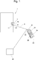
- the 1 and 2 show schematically an access control system for a closed by a door 1 space.
- the door 1 is equipped with an electronic door lock 2 and a receiver unit 10 which has a memory unit 11 and an interface 12 .
- the access control system also includes a central processing unit 50 and a mobile communication unit in the form of a mobile phone 20 which has a memory unit 21, an interface 22, a display 23 and a keyboard 24.
- An electronic key in the form of an access code is required to release the door lock 2 , which is generated by the central computer unit 50 and transmitted wirelessly or by wire to the cell phone 20 and stored in its memory unit 21 .
- the access control system has an RFID transmitter part 30 assigned to the mobile phone 20 and an RFID receiver part 40 assigned to the receiver unit 10 .
- the RFID transmitter part 30 sends out an activation signal with a predetermined range R at predetermined times. In the present case, the range R is up to approximately one meter.
- the RFID receiver part 40 is set up to receive the activation signal. This means that if a user carries the communication unit 20 inside a building and is in the area of the door 1, the activation signal sent out by the RFID transmitter part 30 is then received by the RFID receiver part 40 when the mobile phone 20 and thus the user is at a distance of less than one meter from the receiver unit 10 of the door 1.
- a control signal for activating the receiver unit 10 is sent out.
- This control signal causes the power supply of the door lock 2 to be switched on.
- the receiver unit 10 is provided with additional circuitry.
- the mobile phone 20 sends the access code stored in the memory unit 21 via its interface 22 by means of wireless data transmission using the Bluetooth standard to the receiver unit 10.
- the receiver unit 10 receives the additional code via its interface 12 and compares it with one in the Storage unit 11 stored original access code. If the original access code matches the received access code, i.e. after a successful check, the receiver unit 10 sends an opening control signal to the door lock 2, as a result of which access to the door 1 is released.
- the access control system shown is used to carry out an alternative procedure, which is not claimed, and differs from the access control system according to 1 in that the RFID transmitter part 30 is assigned to the receiver unit 10 and the RFID receiver part 40 to the communication unit 20 .
- the receiver unit 10 transmits the activation signal with the predetermined range R on the basis of this assignment. Accordingly, the mobile phone 20 carried by the user is set up by means of the RFID receiver part 40 to receive the activation signal. In turn, reception is only possible if the cell phone 20 and thus the user are within range R, ie at a distance of less than one meter from the door lock 2 .
- the RFID receiver part 40 receives the activation signal for at least the predetermined period of time, the receiver unit 10 is activated by switching on the power supply.
- the other procedural steps required to release access correspond to those already mentioned above in connection with 1 explained process steps.
- the methods described are characterized above all by the fact that the receiver unit 10 and in particular its power supply and the power supply of the locking mechanism of the door lock 2 only takes place after receipt of an activation signal transmitted by the mobile phone 20 or the receiver unit 10 . Adequate security is ensured in particular by the fact that the mobile phone 20 can only be used after a successful PIN code query and the transmission of the access code in the same way as the transmission of the activation signal is only possible within a certain range R.
Landscapes
- Physics & Mathematics (AREA)
- General Physics & Mathematics (AREA)
- Engineering & Computer Science (AREA)
- Computer Networks & Wireless Communication (AREA)
- Lock And Its Accessories (AREA)
Description
- Die vorliegende Erfindung betrifft ein Verfahren zur Kontrolle des Zugangs für einen von Personen zugänglichen Bereich, insbesondere für einen durch eine Tür abgeschlossenen Raum. Zur Durchführung des Verfahrens ist eine mobile Kommunikationseinheit, auf der wenigstens ein Zugangscode hinterlegt ist, und eine Empfängereinheit zum Empfangen des Zugangscodes vorgesehen. Der Zugangscode wird von der Kommunikationseinheit an die Empfängereinheit gesendet. Daraufhin überprüft die Empfängereinheit den Zugangscode und gibt den Zugang bei einer erfolgreichen Überprüfung frei.
- Bei modernen Zutrittskontrollsystemen werden zur Personenidentifikation häufig berührungslos arbeitende RFID-Systeme (Radio Frequency Identification) verwendet. Ein derartiges RFID-System umfasst einen Transponder und ein mobiles oder stationäres RFID-Lesegerät. Sendet ein RFID-Lesegerät ein Funksignal aus und befindet sich der im wesentlichen aus einem Mikrochip und einer Antenne bestehende Transponder in der Nähe, das heißt in einem Abstand von wenigen Zentimetern bis einigen Metern, antwortet der Transponder und übermittelt die auf ihm gespeicherten Daten, beispielsweise einen Zugangscode, an die Lesestation. Derartige RFID-Systeme werden auch häufig in Zielrufterminals von Aufzugsanlagen eingesetzt. Dabei besteht allerdings der Nachteil, dass die RFID-Systeme zur Kontaktaufnahme mit dem Transponder andauernd ein elektromagnetisches Feld abstrahlen müssen und somit verhältnismäßig viel elektrische Energie verbrauchen.
- Aus der
EP 0 699 617 B1 ist eine Aufzugsanlage mit einer Erkennungsvorrichtung zum Erkennen von einem auf einem Stockwerk abgegebenen Ruf bekannt. Dieser Ruf wird einer Steuereinrichtung zugeführt, die mittels eines Zuteilungsalgorithmus einen Aufzug ermittelt und diesen Aufzug dem Benutzer mitteilt. Die jeweils im Zugangsbereich zu den Aufzügen auf den jeweiligen Stockwerken stationär angeordneten Erkennungsvorrichtungen, die auch als Zielrufterminals bezeichnet werden, strahlen permanent ein elektromagnetisches Feld aus. Sobald ein von dem Benutzer mitgeführter Informationsgeber in das elektromagnetische Feld gelangt, wird der Informationsgeber in Folge des elektromagnetischen Feldes geweckt und sendet die auf ihm gespeicherten Daten, wie beispielsweise einen Identifikationscode, an die Erkennungsvorrichtung. - Bei der vorbeschriebenen Aufzugsanlage ergibt sich allerdings der Nachteil, dass die auf den einzelnen Stockwerken befindlichen Erkennungsvorrichtungen permanent ein elektromagnetisches Feld abstrahlen, um eine Kontaktaufnahme mit dem Informationsgeber zu ermöglichen.
- Das Dokument
WO 2005/054609 offenbart ein Verfahren zur Kontrolle des Zugangs eines Raums mit elektronischen Schlüsseln. Das DokumentDE 10246663 offenbart ein Zutrittskontrollsystem für Türen, wobei zur Identifikation einer berechtigten Person ein Mobiltelefon verwendet wird. - Der Erfindung liegt die Aufgabe zu Grunde, ein Verfahren zur Kontrolle des Zugangs für einen von Personen zugänglichen Bereich so weiterzubilden, dass es im Vergleich zu herkömmlichen Verfahren eines geringeren Energieverbrauches bedarf.
- Zur Lösung dieser Aufgabe ist in Anspruch 1 ein Verfahren zur Kontrolle des Zugangs für einen von Personen zugänglichen Bereich, insbesondere für einen durch eine Tür abgeschlossenen Raum, angegeben.
- Das Verfahren beruht auf der Erkenntnis, dass eine Energieeinsparung gerade dann erzielt werden kann, wenn die Empfängereinheit temporär von einem deaktivierten Zustand in einen aktivierten Zustand und vice versa versetzt werden kann.
- Das erfindungsgemässe Verfahren ermöglicht es, dass die Stromversorgung der Empfängereinheit im Vergleich zu herkömmlichen Verfahren erheblich reduziert wird. Der Grund dafür liegt vor allem darin, dass die Energieversorgung in Abhängigkeit von der Frequentierung der Zugangskontrolle des abgeschlossenen Bereiches gesteuert wird. Auf diese Weise lässt sich insbesondere dann, wenn ein von Personen zugänglicher Bereich, insbesondere ein Gebäude oder ein Raum innerhalb dieses Gebäudes, über einen längeren Zeitraum nicht benutzt wird und dadurch die Empfängereinheit über einen längeren Zeitraum in ihrem deaktivierten Zustand verbleibt, eine Reduzierung des Strombedarfs erzielen.
- Weiterhin erweist es sich als vorteilhaft, dass zur Durchführung des Verfahrens herkömmliche Mobiltelefone einsetzbar sind, so dass der Benutzer neben seinem Mobiltelefon keine weitere Kommunikationseinheit mitführen muss.
- Mit der Erfindung wird ein Verfahren bereitgestellt, das vorzugsweise für die Zugangskontrolle von Aufzügen und Gebäuden, Büros, Wohnungen und einzelnen Räumen in derartigen von Personen zugänglichen Bereichen eingesetzt wird. Zur Übermittlung der Daten in Form von Codesequenzen, die neben dem Zugangscode weitere Daten beinhalten können, wird vorzugsweise eine drahtlose, funkbasierte Kommunikation zwischen den Einheiten verwendet. Der Begriff "Einheit" ist im Sinne der vorliegenden Erfindung als ein Oberbegriff für die Kommunikationseinheit(en) und die Empfängereinheit zu verstehen.
- Als Kommunikationsnetzwerk ist vorzugsweise ein Nahfeld-Kommunikationssystem vorgesehen. Dies bedeutet, dass die Kommunikation zwischen den jeweiligen Einheiten nur innerhalb eines Nahfeldes möglich ist. Hierbei wird als bevorzugter Übertragungsstandard der Bluetooth- oder der NFC-Standard verwendet. Auf diese Weise kann sichergestellt werden, dass kein unerlaubter Zugriff auf das Kommunikationsnetzwerk erfolgt und möglicherweise Zugangscodes ausspioniert werden.
- Vorteilhafte Weiterbildungen des erfindungsgemäßen Verfahrens sind in den Unteransprüchen beschrieben.
- Bei einer vorteilhaften Weiterbildung ist vorgesehen, dass das Aktivierungssignal durch eine Betätigung eines Schalters ausgesendet wird. Diese Maßnahme ermöglicht eine weitere Reduzierung bei der Stromversorgung, da die zur Aussendung des Aktivierungssignals benötigte Energie erst nach Betätigung des Schalters erforderlich wird. Der Schalter kann einerseits im Bereich der Empfängereinheit vorgesehen sein, beispielsweise im Bereich einer Tür, und so bei Bedarf durch den Benutzer betätigt werden. Zur Betätigung des Schalters kann es beispielsweise ausreichend sein, dass ein druck- oder temperaturabhängiger Sensor aktiviert wird und dadurch der Schalter betätigt wird. Andererseits kann der Schalter auch der mobilen Kommunikationseinheit, beispielsweise einem Mobiltelefon, zugeordnet sein und durch Drücken einer Taste oder durch einen Sprachbefehl betätigt werden.
- In Weiterbildung des erfindungsgemäßen Verfahrens wird vorgeschlagen, dass die Empfängereinheit nach der Freigabe des Zugangs deaktiviert wird. Dies ermöglicht eine zusätzliche Reduzierung der Energieversorgung und eignet sich insbesondere für wenig frequentierte Bereiche.
- Bei dem erfindungsgemässen Verfahren ist vorgesehen, dass der Zugangscode nur dann gesendet wird, wenn sich die Kommunikationseinheit innerhalb der Reichweite befindet. Vorzugsweise beträgt die Reichweite weniger als 5 m, zweckmäßigerweise weniger als 1 m. So kann beispielsweise der Zugangscode von der Kommunikationseinheit nur dann an die Empfängereinheit übertragen werden, wenn die beiden Einheiten nahe aneinander gehalten werden, beispielsweise in einer Entfernung von wenigen Zentimetern. Für eine derartige drahtlose, funkbasierte Datenübertragung können herkömmliche Schnittstellen, insbesondere Infrarotschnittstellen, und als Übertragungsstandard insbesondere der Bluetooth-Standard verwendet werden.
- Von Vorteil ist ferner, wenn der Zugangscode nur innerhalb einer vorbestimmten Zeitdauer gesendet wird. Dadurch wird verhindert, dass der Übertragungsvorgang des Zugangscodes durch den Benutzer beendet werden muss und dass sich möglicherweise unbefugte Personen Zutritt verschaffen können. In diesem Zusammenhang erweist es sich weiterhin als vorteilhaft, wenn der Zugang nur innerhalb einer vorbestimmten Zeitdauer freigegeben wird. So kann festgelegt werden, dass der Zugang beispielsweise nach einer Minute gesperrt wird, um möglicherweise nachfolgenden, nicht berechtigten Personen keine Möglichkeit des Zugangs zu bieten.
- Nachfolgend wird die Erfindung unter Bezugnahme auf die Zeichnungen weiter erläutert. Dabei zeigen schematisch:
- Fig. 1
- ein Zugangskontrollsystem zur Durchführung des erfindungsgemäßen Verfahrens und
- Fig. 2
- ein Zugangskontrollsystem zur Durchführung eines alternativen Verfahrens.
- Die
Fig. 1 und2 zeigen schematisch ein Zugangskontrollsystem für einen durch eine Tür 1 abgeschlossenen Raum. Die Tür 1 ist mit einem elektronischen Türschloss 2 und einer Empfängereinheit 10, die eine Speichereinheit 11 und eine Schnittstelle 12 aufweist, ausgestattet. Das Zutrittskontrollsystem umfasst ferner eine zentrale Rechnereinheit 50 und eine mobile Kommunikationseinheit in Form eines Mobiltelefons 20, das eine Speichereinheit 21, eine Schnittstelle 22, ein Display 23 und eine Tastatur 24 aufweist. Zur Freigabe des Türschlosses 2 ist ein elektronischer Schlüssel in Form eines Zugangscodes erforderlich, der von der zentralen Rechnereinheit 50 generiert und drahtlos oder drahtgebunden an das Mobiltelefon 20 übermittelt und in dessen Speichereinheit 21 hinterlegt wird. - Zur Durchführung des Verfahrens zur Kontrolle des Zugangs zu der Tür 1 weist das Zutrittskontrollsystem ein dem Mobiltelefon 20 zugeordnetes RFID-Sendeteil 30 und ein der Empfängereinheit 10 zugeordnetes RFID-Empfängerteil 40 auf. Das RFID-Sendeteil 30 sendet zu vorbestimmten Zeiten ein Aktivierungssignal mit einer vorbestimmten Reichweite R aus. Im vorliegenden Fall beträgt die Reichweite R bis zu circa einem Meter. Das RFID-Empfängerteil 40 ist zum Empfang des Aktivierungssignals eingerichtet. Dies bedeutet, dass, wenn ein Benutzer die Kommunikationseinheit 20 innerhalb eines Gebäudes mit sich führt und sich im Bereich der Tür 1 befindet, das von dem RFID-Sendeteil 30 ausgesendete Aktivierungssignal dann von dem RFID-Empfängerteil 40 empfangen wird, wenn sich das Mobiltelefon 20 und somit der Benutzer in einer Entfernung von weniger als einem Meter von der Empfängereinheit 10 der Tür 1 befindet. Falls das RFID-Empfängerteil 40 das Aktivierungssignal über einen vorbestimmten Zeitraum ununterbrochen empfangen hat, wird ein Steuersignal zur Aktivierung der Empfängereinheit 10 ausgesendet. Dieses Steuersignal bewirkt, dass die Stromversorgung des Türschlosses 2 eingeschaltet wird. Um dies zu ermöglichen, ist die Empfängereinheit 10 mit einem zusätzlichen Schaltkreis versehen. Als nächsten Schritt sendet das Mobiltelefon 20 über seine Schnittstelle 22 den in der Speichereinheit 21 hinterlegten Zugangscode mittels einer drahtlosen Datenübermittlung unter Verwendung des Bluetooth-Standards an die Empfängereinheit 10. Die Empfängereinheit 10 empfängt den Zusatzcode über ihre Schnittstelle 12 und vergleicht diesen mit einem in der Speichereinheit 11 hinterlegten Original-Zugangscode. Bei einer Übereinstimmung des Original-Zugangscodes mit dem empfangenen Zugangscode, das heisst nach einer erfolgreichen Überprüfung, sendet die Empfängereinheit 10 ein Steuersignal zur Öffnung an das Türschloss 2, wodurch der Zugang zu der Tür 1 freigegeben wird.
- Das in
Fig. 2 gezeigte Zugangskontrollsystem dient zur Durchführung eines alternativen Verfahrens, das nicht beansprucht ist, und unterscheidet sich von dem Zugangskontrollsystem gemäßFig. 1 dadurch, dass das RFID-Sendeteil 30 der Empfängereinheit 10 und das RFID-Empfängerteil 40 der Kommunikationseinheit 20 zugeordnet ist. Aufgrund dieser Zuordnung sendet die Empfängereinheit 10 das Aktivierungssignal mit der vorbestimmten Reichweite R aus. Dementsprechend ist das von dem Benutzer mitgeführte Mobiltelefon 20 mittels des RFID-Empfängerteils 40 eingerichtet, das Aktivierungssignal zu empfangen. Der Empfang ist wiederum nur dann möglich, wenn sich das Mobiltelefon 20 und somit der Benutzer innerhalb der Reichweite R, das heißt in einer Entfernung von weniger als einem Meter von dem Türschloss 2 entfernt, befindet. Sobald das RFID-Empfängerteil 40 das Aktivierungssignal zumindest über die vorbestimmte Zeitdauer empfängt, wird die Empfängereinheit 10 durch Einschaltung der Stromversorgung aktiviert. Die übrigen zur Freigabe des Zugangs erforderlichen Verfahrensschritte entsprechen den bereits oben im Zusammenhang mitFig. 1 erläuterten Verfahrensschritten. - Um auch höchsten Sicherheitsanforderungen ausreichend Rechnung zu tragen, kann bei beiden vorbeschriebenen Varianten des Verfahrens vorgesehen werden, dass vordem Senden des Zugangscodes von dem Mobiltelefon 20 an die Empfängereinheit 10 eine PIN-Code-Abfrage mittels des Mobiltelefons 20 erfolgt.
- Die beschriebenen Verfahren zeichnen sich vor allem dadurch aus, dass die Empfängereinheit 10 und insbesondere deren Stromversorgung sowie die Stromversorgung des Verriegelungsmechanismus des Türschlosses 2 erst nach Empfang eines durch das Mobiltelefon 20 oder die Empfängereinheit 10 ausgesendeten Aktivierungssignals erfolgt. Dabei wird eine ausreichende Sicherheit insbesondere dadurch gewährleistet, dass das Mobiltelefon 20 erst nach einer erfolgreichen PIN-Code-Abfrage benutzbar ist und die Übermittlung des Zugangscodes in gleicher Weise wie die Übertragung des Aktivierungssignals nur innerhalb einer bestimmten Reichweite R möglich ist.
Claims (8)
- Verfahren zur Kontrolle des Zugangs für einen von Personen zugänglichen Bereich, insbesondere für einen durch eine Tür (1) abgeschlossenen Raum, mit einer mobilen Kommunikationseinheit (20), auf der wenigstens ein Zugangscode hinterlegt ist, und mit einer Empfängereinheit (10) zum Empfangen des Zugangscodes, wobei das Verfahren folgende Schritte umfasst:a) Senden eines Aktivierungssignals durch die Kommunikationseinheit (20) zu vorbestimmten Zeiten und mit einer vorbestimmten Reichweite (R) von circa einem Meter;b) Aktivierung der Empfängereinheit (10), wenn die Empfängereinheit (10) sich innerhalb der Reichweite (R) des Aktivierungssignals befindet und das Aktivierungssignal über einen vorbestimmten Zeitraum ununterbrochen empfängt;c) Senden des Zugangscodes von der Kommunikationseinheit (20) an die Empfängereinheit (10), wobei der Zugangscode nur dann gesendet wird, wenn sich die Kommunikationseinheit (20) innerhalb der Reichweite (R) befindet;d) Überprüfung des Zugangscodes durch die Empfängereinheit (10) unde) Freigabe des Zugangs bei einer erfolgreichen Überprüfung, wobei der Zugangscode nach einer vorbestimmten Anzahl von Benutzungen zur Freigabe des Zugangs gelöscht wird.
- Verfahren nach Anspruch 1, dadurch gekennzeichnet, dass das Aktivierungssignal durch eine Betätigung eines Schalters gesendet wird.
- Verfahren nach einem der Ansprüche 1 bis 2, dadurch gekennzeichnet, dass die Empfängereinheit (10) nach der Freigabe des Zugangs deaktiviert wird.
- Verfahren nach einem der Ansprüche 1 bis 3, dadurch gekennzeichnet, dass der Zugangscode nur innerhalb einer vorbestimmten Zeitdauer gesendet wird.
- Verfahren nach einem der Ansprüche 1 bis 4, dadurch gekennzeichnet, dass der Zugang nur innerhalb einer vorbestimmten Zeitdauer freigegeben wird.
- Verfahren nach einem der Ansprüche 1 bis 5, dadurch gekennzeichnet, dass eine Rechnereinheit (50) den Zugangscode generiert und an die Kommunikationseinheit (20) übermittelt.
- Verfahren nach einem der Ansprüche 1 bis 6, dadurch gekennzeichnet, dass der Zugangscode wenigstens ein Attribut aufweist, das durch die Rechnereinheit (50) oder durch die Kommunikationseinheit (20) veränderbar ist.
- Verfahren nach einem der Ansprüche 1 bis 8, dadurch gekennzeichnet, dass als Kommunikationseinheit (20) ein Mobiltelefon oder ein PDA (Persönlicher Digitaler Assistent) verwendet wird.
Priority Applications (1)
| Application Number | Priority Date | Filing Date | Title |
|---|---|---|---|
| EP06117600.4A EP1752929B2 (de) | 2005-07-28 | 2006-07-20 | Verfahren zur Kontrolle des Zugangs für einen von Personen zugänglichen Bereich, insbesondere für einen durch eine Tür abgeschlossenen Raum |
Applications Claiming Priority (2)
| Application Number | Priority Date | Filing Date | Title |
|---|---|---|---|
| EP05106997 | 2005-07-28 | ||
| EP06117600.4A EP1752929B2 (de) | 2005-07-28 | 2006-07-20 | Verfahren zur Kontrolle des Zugangs für einen von Personen zugänglichen Bereich, insbesondere für einen durch eine Tür abgeschlossenen Raum |
Publications (3)
| Publication Number | Publication Date |
|---|---|
| EP1752929A1 EP1752929A1 (de) | 2007-02-14 |
| EP1752929B1 EP1752929B1 (de) | 2018-10-03 |
| EP1752929B2 true EP1752929B2 (de) | 2022-06-22 |
Family
ID=37603899
Family Applications (1)
| Application Number | Title | Priority Date | Filing Date |
|---|---|---|---|
| EP06117600.4A Active EP1752929B2 (de) | 2005-07-28 | 2006-07-20 | Verfahren zur Kontrolle des Zugangs für einen von Personen zugänglichen Bereich, insbesondere für einen durch eine Tür abgeschlossenen Raum |
Country Status (1)
| Country | Link |
|---|---|
| EP (1) | EP1752929B2 (de) |
Families Citing this family (2)
| Publication number | Priority date | Publication date | Assignee | Title |
|---|---|---|---|---|
| NL1033539C2 (nl) * | 2007-03-13 | 2008-09-17 | Nedap Nv | Toegangscontrolesysteem met mobiele telefoon. |
| CN101852044A (zh) * | 2010-05-11 | 2010-10-06 | 佛山市顺德区安能保险柜制造有限公司 | 手持遥控式保险柜控制系统及其控制方法 |
Citations (3)
| Publication number | Priority date | Publication date | Assignee | Title |
|---|---|---|---|---|
| US4509093A (en) † | 1982-07-09 | 1985-04-02 | Hulsbeck & Furst Gmbh & Co. Kg | Electronic locking device having key and lock parts interacting via electrical pulses |
| US20020180582A1 (en) † | 1999-11-30 | 2002-12-05 | Nielsen Ernst Lykke | Electronic key device a system and a method of managing electronic key information |
| WO2005054609A1 (en) † | 2003-12-08 | 2005-06-16 | Abloy Oy | Locking system and method for locking system |
Family Cites Families (9)
| Publication number | Priority date | Publication date | Assignee | Title |
|---|---|---|---|---|
| US4779090A (en) | 1986-08-06 | 1988-10-18 | Micznik Isaiah B | Electronic security system with two-way communication between lock and key |
| DE4438832A1 (de) | 1994-10-31 | 1996-05-02 | Diehl Gmbh & Co | Schloß mit Identträger-Aktivierung |
| JPH08254050A (ja) * | 1995-03-17 | 1996-10-01 | Toshiba Corp | 入退室管理装置 |
| US5937065A (en) | 1997-04-07 | 1999-08-10 | Eaton Corporation | Keyless motor vehicle entry and ignition system |
| DE19838129C2 (de) * | 1998-08-21 | 2000-10-12 | Simons & Vos Identifikationssy | Elektronisches Schließsystem |
| JP4214199B2 (ja) * | 2001-11-19 | 2009-01-28 | 株式会社デンソー | 車両のドアアンロック装置 |
| FR2843256B1 (fr) * | 2002-07-31 | 2005-08-05 | Somfy Sas | Procede de caracterisation d'objets bidirectionnels |
| DE10246663A1 (de) * | 2002-10-07 | 2004-04-15 | Dorma Gmbh + Co. Kg | Zutrittskontrollsystem für Türen und Verfahren zum Betrieb eines solchen Zutrittskontrollsystemes |
| EP1424861A1 (de) * | 2002-11-26 | 2004-06-02 | Siemens Aktiengesellschaft | Verfahren und Vorrichtung zur Identifizierung eines Benutzers mittels eines mobilen Endgerätes |
-
2006
- 2006-07-20 EP EP06117600.4A patent/EP1752929B2/de active Active
Patent Citations (3)
| Publication number | Priority date | Publication date | Assignee | Title |
|---|---|---|---|---|
| US4509093A (en) † | 1982-07-09 | 1985-04-02 | Hulsbeck & Furst Gmbh & Co. Kg | Electronic locking device having key and lock parts interacting via electrical pulses |
| US20020180582A1 (en) † | 1999-11-30 | 2002-12-05 | Nielsen Ernst Lykke | Electronic key device a system and a method of managing electronic key information |
| WO2005054609A1 (en) † | 2003-12-08 | 2005-06-16 | Abloy Oy | Locking system and method for locking system |
Also Published As
| Publication number | Publication date |
|---|---|
| EP1752929B1 (de) | 2018-10-03 |
| EP1752929A1 (de) | 2007-02-14 |
Similar Documents
| Publication | Publication Date | Title |
|---|---|---|
| EP1702306B1 (de) | Zutrittskontrollsystem und verfahren zu dessen betrieb | |
| KR101308802B1 (ko) | 사람이 액세스할 수 있는 영역, 특히, 도어에 의해폐쇄되는 영역에 대한 액세스를 제어하는 방법 | |
| EP1748396B1 (de) | Verfahren zum Austausch von Daten | |
| DE60120644T2 (de) | Drahtlose reservierung, check-in, zugangskontrolle, check-out, und bezahlung | |
| JP5436748B2 (ja) | 人が出入りできる区域、特に扉によって閉ざされた空間への出入りを規制する方法 | |
| EP3307666A1 (de) | Aufzugsystem mit prädiktiver ruferzeugung | |
| DE112012006728T5 (de) | Aufzugplattformvorrichtung | |
| EP3729385B1 (de) | Zugangskontrollsystem mit funk-authentifizierung und kennworterfassung | |
| CN100524369C (zh) | 控制进入人员可进入的区域、特别是门关闭的空间的方法 | |
| DE102012205379A1 (de) | Verfahren und System zur Durchführung einer Gebäudezugangskontrolle | |
| WO2020058059A1 (de) | Zugangssystem und verfahren zur zugangsverifizierung | |
| EP1752929B2 (de) | Verfahren zur Kontrolle des Zugangs für einen von Personen zugänglichen Bereich, insbesondere für einen durch eine Tür abgeschlossenen Raum | |
| EP1900672B1 (de) | Verfahren zur Modernisierung der Steuerung einer Aufzugsanlage | |
| JP2009059085A (ja) | セキュリティシステム | |
| EP2350981B1 (de) | Zugangskontroll- und -steuersystem | |
| AT503659A4 (de) | Schlüssel, schliesssystem und schlüsselsicherungssystem | |
| WO2023117535A1 (de) | Aufzugsanlage mit aufzugsnutzungsregeln bei gebäudetüröffnung | |
| EP3965076B1 (de) | Verfahren zur zugangssteuerung | |
| DE10144936A1 (de) | Verfahren zur Prüfung der Zugangsberechtigung | |
| EP1755085B1 (de) | Verfahren zur Kontrolle des Zugangs für eine Tür einer Aufzugsanlage | |
| DE10209890A1 (de) | Verfahren zum Betreiben einer elektromechanischen Schließanlage für Türen in Gebäuden | |
| EP4424035B1 (de) | Verfahren zur steuerung des personenflusses in einem steuerbereich | |
| DE202026100571U1 (de) | Zugangskontrollsystem für Gebäude mit Anzeigevorrichtung | |
| EP1752928A1 (de) | Verfahren zur Kontrolle des Zugangs für einen von Personen zugänglichen Bereich, insbesondere für einen durch eine Tür abgeschlossenen Raum | |
| EP3627460B1 (de) | Zugangssteuerungssystem |
Legal Events
| Date | Code | Title | Description |
|---|---|---|---|
| PUAI | Public reference made under article 153(3) epc to a published international application that has entered the european phase |
Free format text: ORIGINAL CODE: 0009012 |
|
| AK | Designated contracting states |
Kind code of ref document: A1 Designated state(s): AT BE BG CH CY CZ DE DK EE ES FI FR GB GR HU IE IS IT LI LT LU LV MC NL PL PT RO SE SI SK TR |
|
| AX | Request for extension of the european patent |
Extension state: AL BA HR MK YU |
|
| 17P | Request for examination filed |
Effective date: 20070814 |
|
| 17Q | First examination report despatched |
Effective date: 20070920 |
|
| AKX | Designation fees paid |
Designated state(s): AT CH DE FI FR GB LI |
|
| REG | Reference to a national code |
Ref country code: HK Ref legal event code: DE Ref document number: 1102454 Country of ref document: HK |
|
| GRAP | Despatch of communication of intention to grant a patent |
Free format text: ORIGINAL CODE: EPIDOSNIGR1 |
|
| STAA | Information on the status of an ep patent application or granted ep patent |
Free format text: STATUS: GRANT OF PATENT IS INTENDED |
|
| INTG | Intention to grant announced |
Effective date: 20180502 |
|
| GRAS | Grant fee paid |
Free format text: ORIGINAL CODE: EPIDOSNIGR3 |
|
| GRAA | (expected) grant |
Free format text: ORIGINAL CODE: 0009210 |
|
| STAA | Information on the status of an ep patent application or granted ep patent |
Free format text: STATUS: THE PATENT HAS BEEN GRANTED |
|
| AK | Designated contracting states |
Kind code of ref document: B1 Designated state(s): AT CH DE FI FR GB LI |
|
| REG | Reference to a national code |
Ref country code: GB Ref legal event code: FG4D Free format text: NOT ENGLISH |
|
| REG | Reference to a national code |
Ref country code: CH Ref legal event code: EP Ref country code: AT Ref legal event code: REF Ref document number: 1049445 Country of ref document: AT Kind code of ref document: T Effective date: 20181015 |
|
| REG | Reference to a national code |
Ref country code: DE Ref legal event code: R096 Ref document number: 502006016052 Country of ref document: DE |
|
| REG | Reference to a national code |
Ref country code: DE Ref legal event code: R026 Ref document number: 502006016052 Country of ref document: DE |
|
| PLBI | Opposition filed |
Free format text: ORIGINAL CODE: 0009260 |
|
| PLAX | Notice of opposition and request to file observation + time limit sent |
Free format text: ORIGINAL CODE: EPIDOSNOBS2 |
|
| 26 | Opposition filed |
Opponent name: GEZE GMBH Effective date: 20190702 |
|
| PLBB | Reply of patent proprietor to notice(s) of opposition received |
Free format text: ORIGINAL CODE: EPIDOSNOBS3 |
|
| PGFP | Annual fee paid to national office [announced via postgrant information from national office to epo] |
Ref country code: FI Payment date: 20210721 Year of fee payment: 16 |
|
| APAH | Appeal reference modified |
Free format text: ORIGINAL CODE: EPIDOSCREFNO |
|
| APBM | Appeal reference recorded |
Free format text: ORIGINAL CODE: EPIDOSNREFNO |
|
| APBP | Date of receipt of notice of appeal recorded |
Free format text: ORIGINAL CODE: EPIDOSNNOA2O |
|
| APBU | Appeal procedure closed |
Free format text: ORIGINAL CODE: EPIDOSNNOA9O |
|
| PUAH | Patent maintained in amended form |
Free format text: ORIGINAL CODE: 0009272 |
|
| STAA | Information on the status of an ep patent application or granted ep patent |
Free format text: STATUS: PATENT MAINTAINED AS AMENDED |
|
| 27A | Patent maintained in amended form |
Effective date: 20220622 |
|
| AK | Designated contracting states |
Kind code of ref document: B2 Designated state(s): AT CH DE FI FR GB LI |
|
| REG | Reference to a national code |
Ref country code: DE Ref legal event code: R102 Ref document number: 502006016052 Country of ref document: DE |
|
| PG25 | Lapsed in a contracting state [announced via postgrant information from national office to epo] |
Ref country code: FI Free format text: LAPSE BECAUSE OF FAILURE TO SUBMIT A TRANSLATION OF THE DESCRIPTION OR TO PAY THE FEE WITHIN THE PRESCRIBED TIME-LIMIT Effective date: 20220622 |
|
| PGFP | Annual fee paid to national office [announced via postgrant information from national office to epo] |
Ref country code: AT Payment date: 20220719 Year of fee payment: 17 |
|
| REG | Reference to a national code |
Ref country code: HK Ref legal event code: AM43 Ref document number: 1102454 Country of ref document: HK |
|
| P01 | Opt-out of the competence of the unified patent court (upc) registered |
Effective date: 20230516 |
|
| REG | Reference to a national code |
Ref country code: DE Ref legal event code: R084 Ref document number: 502006016052 Country of ref document: DE |
|
| REG | Reference to a national code |
Ref country code: AT Ref legal event code: MM01 Ref document number: 1049445 Country of ref document: AT Kind code of ref document: T Effective date: 20230720 |
|
| PG25 | Lapsed in a contracting state [announced via postgrant information from national office to epo] |
Ref country code: AT Free format text: LAPSE BECAUSE OF NON-PAYMENT OF DUE FEES Effective date: 20230720 |
|
| PG25 | Lapsed in a contracting state [announced via postgrant information from national office to epo] |
Ref country code: AT Free format text: LAPSE BECAUSE OF NON-PAYMENT OF DUE FEES Effective date: 20230720 |
|
| PGFP | Annual fee paid to national office [announced via postgrant information from national office to epo] |
Ref country code: DE Payment date: 20250728 Year of fee payment: 20 |
|
| PGFP | Annual fee paid to national office [announced via postgrant information from national office to epo] |
Ref country code: GB Payment date: 20250722 Year of fee payment: 20 |
|
| PGFP | Annual fee paid to national office [announced via postgrant information from national office to epo] |
Ref country code: FR Payment date: 20250725 Year of fee payment: 20 |
|
| PGFP | Annual fee paid to national office [announced via postgrant information from national office to epo] |
Ref country code: CH Payment date: 20250801 Year of fee payment: 20 |