EP1752297A2 - Méthode de fabrication d'une tête d'impression à jet de liquide - Google Patents
Méthode de fabrication d'une tête d'impression à jet de liquide Download PDFInfo
- Publication number
- EP1752297A2 EP1752297A2 EP06016153A EP06016153A EP1752297A2 EP 1752297 A2 EP1752297 A2 EP 1752297A2 EP 06016153 A EP06016153 A EP 06016153A EP 06016153 A EP06016153 A EP 06016153A EP 1752297 A2 EP1752297 A2 EP 1752297A2
- Authority
- EP
- European Patent Office
- Prior art keywords
- flow duct
- recording head
- ink
- duct forming
- oxetane
- Prior art date
- Legal status (The legal status is an assumption and is not a legal conclusion. Google has not performed a legal analysis and makes no representation as to the accuracy of the status listed.)
- Withdrawn
Links
- 239000007788 liquid Substances 0.000 title claims abstract description 25
- 238000004519 manufacturing process Methods 0.000 title description 9
- 239000000463 material Substances 0.000 claims abstract description 46
- -1 oxetane compound Chemical class 0.000 claims abstract description 41
- AHHWIHXENZJRFG-UHFFFAOYSA-N oxetane Chemical compound C1COC1 AHHWIHXENZJRFG-UHFFFAOYSA-N 0.000 claims abstract description 33
- 239000011342 resin composition Substances 0.000 claims abstract description 32
- 239000003999 initiator Substances 0.000 claims abstract description 21
- 238000012663 cationic photopolymerization Methods 0.000 claims abstract description 19
- 125000003566 oxetanyl group Chemical group 0.000 claims abstract description 13
- 239000007822 coupling agent Substances 0.000 claims description 16
- BLRPTPMANUNPDV-UHFFFAOYSA-N Silane Chemical group [SiH4] BLRPTPMANUNPDV-UHFFFAOYSA-N 0.000 claims description 6
- 229920003986 novolac Polymers 0.000 claims description 6
- 229910000077 silane Inorganic materials 0.000 claims description 6
- 125000003118 aryl group Chemical group 0.000 claims description 5
- 229920005989 resin Polymers 0.000 description 48
- 239000011347 resin Substances 0.000 description 48
- 239000000758 substrate Substances 0.000 description 45
- 239000010410 layer Substances 0.000 description 34
- 239000010408 film Substances 0.000 description 22
- 239000003822 epoxy resin Substances 0.000 description 15
- 229920000647 polyepoxide Polymers 0.000 description 15
- 239000011248 coating agent Substances 0.000 description 14
- 238000000576 coating method Methods 0.000 description 14
- 150000002921 oxetanes Chemical class 0.000 description 14
- 238000001723 curing Methods 0.000 description 10
- 239000000203 mixture Substances 0.000 description 10
- 239000002904 solvent Substances 0.000 description 10
- 230000004913 activation Effects 0.000 description 9
- 230000000052 comparative effect Effects 0.000 description 9
- 125000002723 alicyclic group Chemical group 0.000 description 8
- RTAQQCXQSZGOHL-UHFFFAOYSA-N Titanium Chemical compound [Ti] RTAQQCXQSZGOHL-UHFFFAOYSA-N 0.000 description 7
- LYCAIKOWRPUZTN-UHFFFAOYSA-N ethylene glycol Natural products OCCO LYCAIKOWRPUZTN-UHFFFAOYSA-N 0.000 description 7
- 238000000034 method Methods 0.000 description 7
- 239000000243 solution Substances 0.000 description 7
- 239000000126 substance Substances 0.000 description 7
- YXFVVABEGXRONW-UHFFFAOYSA-N Toluene Chemical compound CC1=CC=CC=C1 YXFVVABEGXRONW-UHFFFAOYSA-N 0.000 description 6
- 239000004593 Epoxy Substances 0.000 description 5
- QCWXUUIWCKQGHC-UHFFFAOYSA-N Zirconium Chemical compound [Zr] QCWXUUIWCKQGHC-UHFFFAOYSA-N 0.000 description 5
- 239000000654 additive Substances 0.000 description 5
- 150000004945 aromatic hydrocarbons Chemical class 0.000 description 5
- 229920006317 cationic polymer Polymers 0.000 description 5
- 150000001875 compounds Chemical class 0.000 description 5
- 239000003208 petroleum Substances 0.000 description 5
- 229920002120 photoresistant polymer Polymers 0.000 description 5
- 229920000642 polymer Polymers 0.000 description 5
- 229910052726 zirconium Inorganic materials 0.000 description 5
- 125000004169 (C1-C6) alkyl group Chemical group 0.000 description 4
- XAGFODPZIPBFFR-UHFFFAOYSA-N aluminium Chemical compound [Al] XAGFODPZIPBFFR-UHFFFAOYSA-N 0.000 description 4
- 229910052782 aluminium Inorganic materials 0.000 description 4
- 125000002091 cationic group Chemical group 0.000 description 4
- 238000005336 cracking Methods 0.000 description 4
- 125000004435 hydrogen atom Chemical group [H]* 0.000 description 4
- 238000000059 patterning Methods 0.000 description 4
- 230000002463 transducing effect Effects 0.000 description 4
- ZWEHNKRNPOVVGH-UHFFFAOYSA-N 2-Butanone Chemical compound CCC(C)=O ZWEHNKRNPOVVGH-UHFFFAOYSA-N 0.000 description 3
- BWLBGMIXKSTLSX-UHFFFAOYSA-N 2-hydroxyisobutyric acid Chemical compound CC(C)(O)C(O)=O BWLBGMIXKSTLSX-UHFFFAOYSA-N 0.000 description 3
- XEKOWRVHYACXOJ-UHFFFAOYSA-N Ethyl acetate Chemical compound CCOC(C)=O XEKOWRVHYACXOJ-UHFFFAOYSA-N 0.000 description 3
- CTQNGGLPUBDAKN-UHFFFAOYSA-N O-Xylene Chemical compound CC1=CC=CC=C1C CTQNGGLPUBDAKN-UHFFFAOYSA-N 0.000 description 3
- DNIAPMSPPWPWGF-UHFFFAOYSA-N Propylene glycol Chemical compound CC(O)CO DNIAPMSPPWPWGF-UHFFFAOYSA-N 0.000 description 3
- XUIMIQQOPSSXEZ-UHFFFAOYSA-N Silicon Chemical compound [Si] XUIMIQQOPSSXEZ-UHFFFAOYSA-N 0.000 description 3
- UMHKOAYRTRADAT-UHFFFAOYSA-N [hydroxy(octoxy)phosphoryl] octyl hydrogen phosphate Chemical compound CCCCCCCCOP(O)(=O)OP(O)(=O)OCCCCCCCC UMHKOAYRTRADAT-UHFFFAOYSA-N 0.000 description 3
- 230000000996 additive effect Effects 0.000 description 3
- 238000004140 cleaning Methods 0.000 description 3
- 230000003247 decreasing effect Effects 0.000 description 3
- 238000011156 evaluation Methods 0.000 description 3
- 238000004299 exfoliation Methods 0.000 description 3
- 230000001747 exhibiting effect Effects 0.000 description 3
- 238000007654 immersion Methods 0.000 description 3
- 125000002496 methyl group Chemical group [H]C([H])([H])* 0.000 description 3
- 239000000178 monomer Substances 0.000 description 3
- 239000003505 polymerization initiator Substances 0.000 description 3
- 238000002360 preparation method Methods 0.000 description 3
- 239000004065 semiconductor Substances 0.000 description 3
- 229910052710 silicon Inorganic materials 0.000 description 3
- 239000010703 silicon Substances 0.000 description 3
- DQZNLOXENNXVAD-UHFFFAOYSA-N trimethoxy-[2-(7-oxabicyclo[4.1.0]heptan-4-yl)ethyl]silane Chemical compound C1C(CC[Si](OC)(OC)OC)CCC2OC21 DQZNLOXENNXVAD-UHFFFAOYSA-N 0.000 description 3
- 229920002554 vinyl polymer Polymers 0.000 description 3
- 239000008096 xylene Substances 0.000 description 3
- 125000003903 2-propenyl group Chemical group [H]C([*])([H])C([H])=C([H])[H] 0.000 description 2
- RTZKZFJDLAIYFH-UHFFFAOYSA-N Diethyl ether Chemical compound CCOCC RTZKZFJDLAIYFH-UHFFFAOYSA-N 0.000 description 2
- LFQSCWFLJHTTHZ-UHFFFAOYSA-N Ethanol Chemical compound CCO LFQSCWFLJHTTHZ-UHFFFAOYSA-N 0.000 description 2
- 239000004838 Heat curing adhesive Substances 0.000 description 2
- ISWSIDIOOBJBQZ-UHFFFAOYSA-N Phenol Chemical compound OC1=CC=CC=C1 ISWSIDIOOBJBQZ-UHFFFAOYSA-N 0.000 description 2
- 239000006087 Silane Coupling Agent Substances 0.000 description 2
- WDJHALXBUFZDSR-UHFFFAOYSA-M acetoacetate Chemical compound CC(=O)CC([O-])=O WDJHALXBUFZDSR-UHFFFAOYSA-M 0.000 description 2
- 239000002253 acid Substances 0.000 description 2
- 125000000484 butyl group Chemical group [H]C([*])([H])C([H])([H])C([H])([H])C([H])([H])[H] 0.000 description 2
- 125000006251 butylcarbonyl group Chemical group 0.000 description 2
- 125000002915 carbonyl group Chemical group [*:2]C([*:1])=O 0.000 description 2
- 229940114081 cinnamate Drugs 0.000 description 2
- 229920001577 copolymer Polymers 0.000 description 2
- JHIVVAPYMSGYDF-UHFFFAOYSA-N cyclohexanone Chemical compound O=C1CCCCC1 JHIVVAPYMSGYDF-UHFFFAOYSA-N 0.000 description 2
- DIOQZVSQGTUSAI-UHFFFAOYSA-N decane Chemical compound CCCCCCCCCC DIOQZVSQGTUSAI-UHFFFAOYSA-N 0.000 description 2
- 238000011161 development Methods 0.000 description 2
- 125000000664 diazo group Chemical group [N-]=[N+]=[*] 0.000 description 2
- XYIBRDXRRQCHLP-UHFFFAOYSA-N ethyl acetoacetate Chemical compound CCOC(=O)CC(C)=O XYIBRDXRRQCHLP-UHFFFAOYSA-N 0.000 description 2
- 125000001495 ethyl group Chemical group [H]C([H])([H])C([H])([H])* 0.000 description 2
- 125000004672 ethylcarbonyl group Chemical group [H]C([H])([H])C([H])([H])C(*)=O 0.000 description 2
- 125000004051 hexyl group Chemical group [H]C([H])([H])C([H])([H])C([H])([H])C([H])([H])C([H])([H])C([H])([H])* 0.000 description 2
- 125000001449 isopropyl group Chemical group [H]C([H])([H])C([H])(*)C([H])([H])[H] 0.000 description 2
- XMGQYMWWDOXHJM-UHFFFAOYSA-N limonene Chemical compound CC(=C)C1CCC(C)=CC1 XMGQYMWWDOXHJM-UHFFFAOYSA-N 0.000 description 2
- 238000005259 measurement Methods 0.000 description 2
- 239000003960 organic solvent Substances 0.000 description 2
- 230000000704 physical effect Effects 0.000 description 2
- 238000011417 postcuring Methods 0.000 description 2
- UOHMMEJUHBCKEE-UHFFFAOYSA-N prehnitene Chemical compound CC1=CC=C(C)C(C)=C1C UOHMMEJUHBCKEE-UHFFFAOYSA-N 0.000 description 2
- 230000008569 process Effects 0.000 description 2
- 230000002035 prolonged effect Effects 0.000 description 2
- 125000001436 propyl group Chemical group [H]C([*])([H])C([H])([H])C([H])([H])[H] 0.000 description 2
- 125000004673 propylcarbonyl group Chemical group 0.000 description 2
- 238000011160 research Methods 0.000 description 2
- 230000035945 sensitivity Effects 0.000 description 2
- 238000007493 shaping process Methods 0.000 description 2
- 238000012360 testing method Methods 0.000 description 2
- WBYWAXJHAXSJNI-VOTSOKGWSA-M trans-cinnamate Chemical compound [O-]C(=O)\C=C\C1=CC=CC=C1 WBYWAXJHAXSJNI-VOTSOKGWSA-M 0.000 description 2
- 125000004400 (C1-C12) alkyl group Chemical group 0.000 description 1
- POILWHVDKZOXJZ-ARJAWSKDSA-M (z)-4-oxopent-2-en-2-olate Chemical compound C\C([O-])=C\C(C)=O POILWHVDKZOXJZ-ARJAWSKDSA-M 0.000 description 1
- JYEUMXHLPRZUAT-UHFFFAOYSA-N 1,2,3-triazine Chemical group C1=CN=NN=C1 JYEUMXHLPRZUAT-UHFFFAOYSA-N 0.000 description 1
- WOAHJDHKFWSLKE-UHFFFAOYSA-N 1,2-benzoquinone Chemical compound O=C1C=CC=CC1=O WOAHJDHKFWSLKE-UHFFFAOYSA-N 0.000 description 1
- ZIKLJUUTSQYGQI-UHFFFAOYSA-N 1-ethoxy-2-(2-ethoxypropoxy)propane Chemical compound CCOCC(C)OCC(C)OCC ZIKLJUUTSQYGQI-UHFFFAOYSA-N 0.000 description 1
- JOLQKTGDSGKSKJ-UHFFFAOYSA-N 1-ethoxypropan-2-ol Chemical compound CCOCC(C)O JOLQKTGDSGKSKJ-UHFFFAOYSA-N 0.000 description 1
- ARXJGSRGQADJSQ-UHFFFAOYSA-N 1-methoxypropan-2-ol Chemical compound COCC(C)O ARXJGSRGQADJSQ-UHFFFAOYSA-N 0.000 description 1
- 125000006017 1-propenyl group Chemical group 0.000 description 1
- OAYXUHPQHDHDDZ-UHFFFAOYSA-N 2-(2-butoxyethoxy)ethanol Chemical compound CCCCOCCOCCO OAYXUHPQHDHDDZ-UHFFFAOYSA-N 0.000 description 1
- VXQBJTKSVGFQOL-UHFFFAOYSA-N 2-(2-butoxyethoxy)ethyl acetate Chemical compound CCCCOCCOCCOC(C)=O VXQBJTKSVGFQOL-UHFFFAOYSA-N 0.000 description 1
- FPZWZCWUIYYYBU-UHFFFAOYSA-N 2-(2-ethoxyethoxy)ethyl acetate Chemical compound CCOCCOCCOC(C)=O FPZWZCWUIYYYBU-UHFFFAOYSA-N 0.000 description 1
- SBASXUCJHJRPEV-UHFFFAOYSA-N 2-(2-methoxyethoxy)ethanol Chemical compound COCCOCCO SBASXUCJHJRPEV-UHFFFAOYSA-N 0.000 description 1
- DRLRGHZJOQGQEC-UHFFFAOYSA-N 2-(2-methoxypropoxy)propyl acetate Chemical compound COC(C)COC(C)COC(C)=O DRLRGHZJOQGQEC-UHFFFAOYSA-N 0.000 description 1
- XNWFRZJHXBZDAG-UHFFFAOYSA-N 2-METHOXYETHANOL Chemical compound COCCO XNWFRZJHXBZDAG-UHFFFAOYSA-N 0.000 description 1
- WFSMVVDJSNMRAR-UHFFFAOYSA-N 2-[2-(2-ethoxyethoxy)ethoxy]ethanol Chemical compound CCOCCOCCOCCO WFSMVVDJSNMRAR-UHFFFAOYSA-N 0.000 description 1
- 125000000022 2-aminoethyl group Chemical group [H]C([*])([H])C([H])([H])N([H])[H] 0.000 description 1
- POAOYUHQDCAZBD-UHFFFAOYSA-N 2-butoxyethanol Chemical compound CCCCOCCO POAOYUHQDCAZBD-UHFFFAOYSA-N 0.000 description 1
- NQBXSWAWVZHKBZ-UHFFFAOYSA-N 2-butoxyethyl acetate Chemical compound CCCCOCCOC(C)=O NQBXSWAWVZHKBZ-UHFFFAOYSA-N 0.000 description 1
- ZNQVEEAIQZEUHB-UHFFFAOYSA-N 2-ethoxyethanol Chemical compound CCOCCO ZNQVEEAIQZEUHB-UHFFFAOYSA-N 0.000 description 1
- SVONRAPFKPVNKG-UHFFFAOYSA-N 2-ethoxyethyl acetate Chemical compound CCOCCOC(C)=O SVONRAPFKPVNKG-UHFFFAOYSA-N 0.000 description 1
- 125000006020 2-methyl-1-propenyl group Chemical group 0.000 description 1
- 125000006022 2-methyl-2-propenyl group Chemical group 0.000 description 1
- ZBRZSJUFJUMKIM-UHFFFAOYSA-N 3-(1-phenylpropan-2-ylamino)propanenitrile;hydrochloride Chemical compound Cl.N#CCCNC(C)CC1=CC=CC=C1 ZBRZSJUFJUMKIM-UHFFFAOYSA-N 0.000 description 1
- OXYZDRAJMHGSMW-UHFFFAOYSA-N 3-chloropropyl(trimethoxy)silane Chemical compound CO[Si](OC)(OC)CCCCl OXYZDRAJMHGSMW-UHFFFAOYSA-N 0.000 description 1
- UUEWCQRISZBELL-UHFFFAOYSA-N 3-trimethoxysilylpropane-1-thiol Chemical compound CO[Si](OC)(OC)CCCS UUEWCQRISZBELL-UHFFFAOYSA-N 0.000 description 1
- XDLMVUHYZWKMMD-UHFFFAOYSA-N 3-trimethoxysilylpropyl 2-methylprop-2-enoate Chemical compound CO[Si](OC)(OC)CCCOC(=O)C(C)=C XDLMVUHYZWKMMD-UHFFFAOYSA-N 0.000 description 1
- WTQZSMDDRMKJRI-UHFFFAOYSA-N 4-diazoniophenolate Chemical compound [O-]C1=CC=C([N+]#N)C=C1 WTQZSMDDRMKJRI-UHFFFAOYSA-N 0.000 description 1
- NIXOWILDQLNWCW-UHFFFAOYSA-M Acrylate Chemical compound [O-]C(=O)C=C NIXOWILDQLNWCW-UHFFFAOYSA-M 0.000 description 1
- 102100033806 Alpha-protein kinase 3 Human genes 0.000 description 1
- 101710082399 Alpha-protein kinase 3 Proteins 0.000 description 1
- DKPFZGUDAPQIHT-UHFFFAOYSA-N Butyl acetate Natural products CCCCOC(C)=O DKPFZGUDAPQIHT-UHFFFAOYSA-N 0.000 description 1
- 125000000882 C2-C6 alkenyl group Chemical group 0.000 description 1
- OKTJSMMVPCPJKN-UHFFFAOYSA-N Carbon Chemical compound [C] OKTJSMMVPCPJKN-UHFFFAOYSA-N 0.000 description 1
- VYZAMTAEIAYCRO-UHFFFAOYSA-N Chromium Chemical compound [Cr] VYZAMTAEIAYCRO-UHFFFAOYSA-N 0.000 description 1
- VGGSQFUCUMXWEO-UHFFFAOYSA-N Ethene Chemical compound C=C VGGSQFUCUMXWEO-UHFFFAOYSA-N 0.000 description 1
- 239000005977 Ethylene Substances 0.000 description 1
- 125000005118 N-alkylcarbamoyl group Chemical group 0.000 description 1
- 229910019142 PO4 Inorganic materials 0.000 description 1
- 239000004721 Polyphenylene oxide Substances 0.000 description 1
- 239000004372 Polyvinyl alcohol Substances 0.000 description 1
- 239000007983 Tris buffer Substances 0.000 description 1
- 150000001242 acetic acid derivatives Chemical class 0.000 description 1
- 150000007513 acids Chemical class 0.000 description 1
- NIXOWILDQLNWCW-UHFFFAOYSA-N acrylic acid group Chemical group C(C=C)(=O)O NIXOWILDQLNWCW-UHFFFAOYSA-N 0.000 description 1
- 239000012790 adhesive layer Substances 0.000 description 1
- 150000001298 alcohols Chemical class 0.000 description 1
- 150000001338 aliphatic hydrocarbons Chemical class 0.000 description 1
- 125000004453 alkoxycarbonyl group Chemical group 0.000 description 1
- 125000000217 alkyl group Chemical group 0.000 description 1
- 125000002947 alkylene group Chemical group 0.000 description 1
- 230000004075 alteration Effects 0.000 description 1
- 150000004645 aluminates Chemical class 0.000 description 1
- 125000003710 aryl alkyl group Chemical group 0.000 description 1
- RWCCWEUUXYIKHB-UHFFFAOYSA-N benzophenone Chemical compound C=1C=CC=CC=1C(=O)C1=CC=CC=C1 RWCCWEUUXYIKHB-UHFFFAOYSA-N 0.000 description 1
- 239000012965 benzophenone Substances 0.000 description 1
- 125000001797 benzyl group Chemical group [H]C1=C([H])C([H])=C(C([H])=C1[H])C([H])([H])* 0.000 description 1
- 125000004744 butyloxycarbonyl group Chemical group 0.000 description 1
- VTJUKNSKBAOEHE-UHFFFAOYSA-N calixarene Chemical class COC(=O)COC1=C(CC=2C(=C(CC=3C(=C(C4)C=C(C=3)C(C)(C)C)OCC(=O)OC)C=C(C=2)C(C)(C)C)OCC(=O)OC)C=C(C(C)(C)C)C=C1CC1=C(OCC(=O)OC)C4=CC(C(C)(C)C)=C1 VTJUKNSKBAOEHE-UHFFFAOYSA-N 0.000 description 1
- 229910052799 carbon Inorganic materials 0.000 description 1
- 150000001721 carbon Chemical group 0.000 description 1
- 230000015556 catabolic process Effects 0.000 description 1
- 238000010538 cationic polymerization reaction Methods 0.000 description 1
- 238000006243 chemical reaction Methods 0.000 description 1
- 229910052804 chromium Inorganic materials 0.000 description 1
- 239000011651 chromium Substances 0.000 description 1
- 238000003776 cleavage reaction Methods 0.000 description 1
- 239000011247 coating layer Substances 0.000 description 1
- 239000000470 constituent Substances 0.000 description 1
- 230000008602 contraction Effects 0.000 description 1
- 238000007334 copolymerization reaction Methods 0.000 description 1
- 238000006731 degradation reaction Methods 0.000 description 1
- 238000013461 design Methods 0.000 description 1
- 230000006866 deterioration Effects 0.000 description 1
- 125000005520 diaryliodonium group Chemical group 0.000 description 1
- FHIVAFMUCKRCQO-UHFFFAOYSA-N diazinon Chemical compound CCOP(=S)(OCC)OC1=CC(C)=NC(C(C)C)=N1 FHIVAFMUCKRCQO-UHFFFAOYSA-N 0.000 description 1
- 239000012954 diazonium Substances 0.000 description 1
- 229940098237 dicel Drugs 0.000 description 1
- SOCTUWSJJQCPFX-UHFFFAOYSA-N dichromate(2-) Chemical compound [O-][Cr](=O)(=O)O[Cr]([O-])(=O)=O SOCTUWSJJQCPFX-UHFFFAOYSA-N 0.000 description 1
- XEJNLUBEFCNORG-UHFFFAOYSA-N ditridecyl hydrogen phosphate Chemical compound CCCCCCCCCCCCCOP(O)(=O)OCCCCCCCCCCCCC XEJNLUBEFCNORG-UHFFFAOYSA-N 0.000 description 1
- FWDBOZPQNFPOLF-UHFFFAOYSA-N ethenyl(triethoxy)silane Chemical compound CCO[Si](OCC)(OCC)C=C FWDBOZPQNFPOLF-UHFFFAOYSA-N 0.000 description 1
- NKSJNEHGWDZZQF-UHFFFAOYSA-N ethenyl(trimethoxy)silane Chemical compound CO[Si](OC)(OC)C=C NKSJNEHGWDZZQF-UHFFFAOYSA-N 0.000 description 1
- 229940052303 ethers for general anesthesia Drugs 0.000 description 1
- 125000003754 ethoxycarbonyl group Chemical group C(=O)(OCC)* 0.000 description 1
- 238000002474 experimental method Methods 0.000 description 1
- 230000002349 favourable effect Effects 0.000 description 1
- 125000003709 fluoroalkyl group Chemical group 0.000 description 1
- 125000004175 fluorobenzyl group Chemical group 0.000 description 1
- 125000000524 functional group Chemical group 0.000 description 1
- 239000011521 glass Substances 0.000 description 1
- 125000003055 glycidyl group Chemical group C(C1CO1)* 0.000 description 1
- FUZZWVXGSFPDMH-UHFFFAOYSA-N hexanoic acid Chemical compound CCCCCC(O)=O FUZZWVXGSFPDMH-UHFFFAOYSA-N 0.000 description 1
- 125000002887 hydroxy group Chemical group [H]O* 0.000 description 1
- WGCNASOHLSPBMP-UHFFFAOYSA-N hydroxyacetaldehyde Natural products OCC=O WGCNASOHLSPBMP-UHFFFAOYSA-N 0.000 description 1
- 230000001939 inductive effect Effects 0.000 description 1
- 239000012948 isocyanate Substances 0.000 description 1
- 150000002576 ketones Chemical class 0.000 description 1
- 235000001510 limonene Nutrition 0.000 description 1
- 229940087305 limonene Drugs 0.000 description 1
- 238000002156 mixing Methods 0.000 description 1
- 238000012986 modification Methods 0.000 description 1
- 230000004048 modification Effects 0.000 description 1
- 230000035772 mutation Effects 0.000 description 1
- 150000004950 naphthalene Chemical class 0.000 description 1
- CAQIWIAAHXOQOS-UHFFFAOYSA-N octadecanoic acid;propan-2-ol;titanium Chemical compound [Ti].CC(C)O.CCCCCCCCCCCCCCCCCC(O)=O.CCCCCCCCCCCCCCCCCC(O)=O.CCCCCCCCCCCCCCCCCC(O)=O CAQIWIAAHXOQOS-UHFFFAOYSA-N 0.000 description 1
- TVMXDCGIABBOFY-UHFFFAOYSA-N octane Chemical compound CCCCCCCC TVMXDCGIABBOFY-UHFFFAOYSA-N 0.000 description 1
- 239000011368 organic material Substances 0.000 description 1
- 125000000466 oxiranyl group Chemical group 0.000 description 1
- 125000001997 phenyl group Chemical group [H]C1=C([H])C([H])=C(*)C([H])=C1[H] 0.000 description 1
- NBIIXXVUZAFLBC-UHFFFAOYSA-K phosphate Chemical compound [O-]P([O-])([O-])=O NBIIXXVUZAFLBC-UHFFFAOYSA-K 0.000 description 1
- 239000010452 phosphate Substances 0.000 description 1
- 239000003504 photosensitizing agent Substances 0.000 description 1
- 229920000570 polyether Polymers 0.000 description 1
- 229920002451 polyvinyl alcohol Polymers 0.000 description 1
- 125000002924 primary amino group Chemical group [H]N([H])* 0.000 description 1
- BDERNNFJNOPAEC-UHFFFAOYSA-N propan-1-ol Chemical compound CCCO BDERNNFJNOPAEC-UHFFFAOYSA-N 0.000 description 1
- LLHKCFNBLRBOGN-UHFFFAOYSA-N propylene glycol methyl ether acetate Chemical compound COCC(C)OC(C)=O LLHKCFNBLRBOGN-UHFFFAOYSA-N 0.000 description 1
- 125000004742 propyloxycarbonyl group Chemical group 0.000 description 1
- 230000005855 radiation Effects 0.000 description 1
- 229930195734 saturated hydrocarbon Natural products 0.000 description 1
- 230000007017 scission Effects 0.000 description 1
- 229920002050 silicone resin Polymers 0.000 description 1
- 239000007787 solid Substances 0.000 description 1
- 150000003458 sulfonic acid derivatives Chemical class 0.000 description 1
- 150000003505 terpenes Chemical class 0.000 description 1
- 235000007586 terpenes Nutrition 0.000 description 1
- 125000001544 thienyl group Chemical group 0.000 description 1
- 239000010409 thin film Substances 0.000 description 1
- 125000005409 triarylsulfonium group Chemical group 0.000 description 1
- NBXZNTLFQLUFES-UHFFFAOYSA-N triethoxy(propyl)silane Chemical compound CCC[Si](OCC)(OCC)OCC NBXZNTLFQLUFES-UHFFFAOYSA-N 0.000 description 1
- BPSIOYPQMFLKFR-UHFFFAOYSA-N trimethoxy-[3-(oxiran-2-ylmethoxy)propyl]silane Chemical compound CO[Si](OC)(OC)CCCOCC1CO1 BPSIOYPQMFLKFR-UHFFFAOYSA-N 0.000 description 1
- 229930195735 unsaturated hydrocarbon Natural products 0.000 description 1
- 229920006305 unsaturated polyester Polymers 0.000 description 1
- 150000003673 urethanes Chemical class 0.000 description 1
- 125000000391 vinyl group Chemical group [H]C([*])=C([H])[H] 0.000 description 1
- XLYOFNOQVPJJNP-UHFFFAOYSA-N water Substances O XLYOFNOQVPJJNP-UHFFFAOYSA-N 0.000 description 1
- SXPUVBFQXJHYNS-UHFFFAOYSA-N α-furil Chemical group C=1C=COC=1C(=O)C(=O)C1=CC=CO1 SXPUVBFQXJHYNS-UHFFFAOYSA-N 0.000 description 1
Images


Classifications
-
- B—PERFORMING OPERATIONS; TRANSPORTING
- B41—PRINTING; LINING MACHINES; TYPEWRITERS; STAMPS
- B41J—TYPEWRITERS; SELECTIVE PRINTING MECHANISMS, i.e. MECHANISMS PRINTING OTHERWISE THAN FROM A FORME; CORRECTION OF TYPOGRAPHICAL ERRORS
- B41J2/00—Typewriters or selective printing mechanisms characterised by the printing or marking process for which they are designed
- B41J2/005—Typewriters or selective printing mechanisms characterised by the printing or marking process for which they are designed characterised by bringing liquid or particles selectively into contact with a printing material
- B41J2/01—Ink jet
- B41J2/135—Nozzles
- B41J2/16—Production of nozzles
- B41J2/1621—Manufacturing processes
- B41J2/1631—Manufacturing processes photolithography
-
- B—PERFORMING OPERATIONS; TRANSPORTING
- B41—PRINTING; LINING MACHINES; TYPEWRITERS; STAMPS
- B41J—TYPEWRITERS; SELECTIVE PRINTING MECHANISMS, i.e. MECHANISMS PRINTING OTHERWISE THAN FROM A FORME; CORRECTION OF TYPOGRAPHICAL ERRORS
- B41J2/00—Typewriters or selective printing mechanisms characterised by the printing or marking process for which they are designed
- B41J2/005—Typewriters or selective printing mechanisms characterised by the printing or marking process for which they are designed characterised by bringing liquid or particles selectively into contact with a printing material
- B41J2/01—Ink jet
- B41J2/135—Nozzles
- B41J2/16—Production of nozzles
- B41J2/1601—Production of bubble jet print heads
- B41J2/1603—Production of bubble jet print heads of the front shooter type
-
- B—PERFORMING OPERATIONS; TRANSPORTING
- B41—PRINTING; LINING MACHINES; TYPEWRITERS; STAMPS
- B41J—TYPEWRITERS; SELECTIVE PRINTING MECHANISMS, i.e. MECHANISMS PRINTING OTHERWISE THAN FROM A FORME; CORRECTION OF TYPOGRAPHICAL ERRORS
- B41J2/00—Typewriters or selective printing mechanisms characterised by the printing or marking process for which they are designed
- B41J2/005—Typewriters or selective printing mechanisms characterised by the printing or marking process for which they are designed characterised by bringing liquid or particles selectively into contact with a printing material
- B41J2/01—Ink jet
- B41J2/135—Nozzles
- B41J2/16—Production of nozzles
- B41J2/1621—Manufacturing processes
- B41J2/1623—Manufacturing processes bonding and adhesion
-
- B—PERFORMING OPERATIONS; TRANSPORTING
- B41—PRINTING; LINING MACHINES; TYPEWRITERS; STAMPS
- B41J—TYPEWRITERS; SELECTIVE PRINTING MECHANISMS, i.e. MECHANISMS PRINTING OTHERWISE THAN FROM A FORME; CORRECTION OF TYPOGRAPHICAL ERRORS
- B41J2/00—Typewriters or selective printing mechanisms characterised by the printing or marking process for which they are designed
- B41J2/005—Typewriters or selective printing mechanisms characterised by the printing or marking process for which they are designed characterised by bringing liquid or particles selectively into contact with a printing material
- B41J2/01—Ink jet
- B41J2/135—Nozzles
- B41J2/16—Production of nozzles
- B41J2/1621—Manufacturing processes
- B41J2/164—Manufacturing processes thin film formation
- B41J2/1645—Manufacturing processes thin film formation thin film formation by spincoating
-
- B—PERFORMING OPERATIONS; TRANSPORTING
- B41—PRINTING; LINING MACHINES; TYPEWRITERS; STAMPS
- B41J—TYPEWRITERS; SELECTIVE PRINTING MECHANISMS, i.e. MECHANISMS PRINTING OTHERWISE THAN FROM A FORME; CORRECTION OF TYPOGRAPHICAL ERRORS
- B41J2202/00—Embodiments of or processes related to ink-jet or thermal heads
- B41J2202/01—Embodiments of or processes related to ink-jet heads
- B41J2202/03—Specific materials used
-
- Y—GENERAL TAGGING OF NEW TECHNOLOGICAL DEVELOPMENTS; GENERAL TAGGING OF CROSS-SECTIONAL TECHNOLOGIES SPANNING OVER SEVERAL SECTIONS OF THE IPC; TECHNICAL SUBJECTS COVERED BY FORMER USPC CROSS-REFERENCE ART COLLECTIONS [XRACs] AND DIGESTS
- Y10—TECHNICAL SUBJECTS COVERED BY FORMER USPC
- Y10T—TECHNICAL SUBJECTS COVERED BY FORMER US CLASSIFICATION
- Y10T29/00—Metal working
- Y10T29/49—Method of mechanical manufacture
- Y10T29/49401—Fluid pattern dispersing device making, e.g., ink jet
Definitions
- the present invention contains subject matter related to Japanese Patent Application JP 2005-229865 filed in the Japanese Patent Office on August 8, 2005 , the entire contents of which being incorporated herein by reference.
- This invention relates to a flow duct forming material for a recording head of the liquid ejecting type which exhibits low stress and high resistance against chemicals and which includes a plural number of flow ducts formed to high accuracy by patterned shaping by e.g. radiation of ultraviolet light.
- an ink jet recording head applied to the ink jet recording system, ejecting e.g. the ink as liquid (liquid jet recording system).
- This ink jet recording head includes several constituent units, namely a plural number of ejecting orifices (orifices) ejecting the ink in a finely divided form, a plural number of flow ducts communicating with these ejecting orifices, and by a plural number of ink ejecting pressure generating devices, provided in certain portions of the flow ducts.
- small ink droplets discharged from the ejecting orifices, are discharged with the same volume and at the same ejecting speed at all times from the respective ejecting orifices.
- Patent Publication 1 JP Laid-Open Patent Publication S56-123869
- Patent Publication 2 JP Laid-Open Patent Publication S57-208255
- Patent Publication 3 JP Laid-Open Patent Publication S57-208256 .
- a plural number of nozzles each including an ink flow duct and an orifice part, are patterned with e.g. a photosensitive resin material or a photoresist, on a substrate carrying a plural number of ink ejecting pressure generating devices.
- a lid formed by, for example, a glass plate.
- the photosensitive resin material or the photoresist include diazo resin, p-diazoquinone, photo-polymerized photopolymers, containing vinyl monomers and a polymerization initiator, dimerized photopolymers, employing e.g. polyvinyl cinnamate and a sensitizer, a mixture of orthoquinone diazide and a phenol novolak resin, and a mixture of polyvinyl alcohol and diazo resin.
- polyether photopolymers obtained on copolymerization of 4-glycidyl ethylene oxide with benzophenone or glycidyl calcone, an N-N- dimethyl methacryl amide-acrylamide benzophenone copolymer, unsaturated polyester based photosensitive resin, unsaturated urethane-based photosensitive resin, and a photosensitive composition obtained on mixing a difunctional acrylic monomer with a photopolymerization initiator and a polymer.
- Further examples include a dichromate photoresist, a non-chromium-based water-soluble photoresist and a polyvinyl cinnamate based photoresist.
- ink jet recording heads satisfying the aforementioned conditions for ejecting, may be exemplified by an ink jet recording head, obtained by a method for preparation as disclosed in Patent Publication 4 ( JP Laid-Open Patent Publication S61-154947 ), indicated below.
- a plural number of ink flow duct patterns are formed on the site of the substrate, which become to be ink flow ducts, with a dissolvable resin, and the so formed ink flow duct patterns are coated with an epoxy resin.
- the substrate is then severed, and the dissolvable resin, which forms the ink flow duct patterns, is dissolved and removed to yield an ink jet recording head.
- an ink jet recording head in which, in contrast to those shown in the Patent Publications 1 to 4, a plural number of electrical thermal transducers, as the ink ejecting pressure generating devices, are mounted facing the ejecting orifices, with the direction of growth of the air bubbles, formed on the electrical thermal transducers, being substantially the same as the ink ejecting direction.
- Examples of this type of the ink jet recording head are disclosed in the Patent Publication 5 ( JP Laid-Open Patent Publication S58-8658 ) and Patent Publication 6 ( JP Laid-Open Patent Publication S62-264957 ), indicated below.
- a dry film which later becomes an orifice plate, is bonded on a substrate, provided with the electrical thermal transducers, with another patterned dry film.
- a plural number of ejecting orifices are formed by a photolithographic technique on the sites facing the electrical thermal transducers of the dry film and which later become an orifice plate.
- the substrate, carrying the ink ejecting pressure generating devices, and an orifice plate, prepared by electrocasting are bonded together via a patterned dry film.
- the distance between the electrical thermal transducer and the ejecting orifice is desirably as short as possible.
- Patent Publication 7 JP Laid-Open Patent Publication H6-286149 .
- a method for preparation of an ink jet recording head including an ink flow duct pattern forming step, a coating resin layer forming step and a dissolvable resin layer dissolving step.
- an ink flow duct pattern which later becomes an ink flow duct, is formed by a dissolvable resin on a substrate already carrying ink ejecting pressure generating devices.
- the coating resin layer forming step the coating resin, containing an epoxy resin, solid at ambient temperature, is dissolved in a solvent and applied by solvent coating on a dissolvable resin layer, forming an ink flow duct pattern, to form a coating resin layer, which later becomes a wall section of an ink flow duct, on the dissolvable resin layer.
- the dissolvable coating layer, forming the ink flow duct pattern is dissolved.
- a cationic polymer of an alicyclic epoxy resin is used as the coating resin from the viewpoint of forming a high aspect ratio pattern and of assuring high resistance against the ink.
- a plural number of heater resistors provided in preset portions of the ink flow ducts to become ink ejecting pressure generating devices, are mounted along a line parallel to the ink flow direction.
- the ink ejecting orifices are provided at terminal parts of the ink flow ducts for extending at right angles to the ink flow direction.
- the ink ejecting direction is perpendicular to the direction of growth of air bubbles on the resistor heaters, that is, the direction of growth of the air bubbles differs from the direction of ink emission.
- the distance between the ink ejecting pressure generating device and the ejecting orifice is set as a result of severing the substrate.
- the accuracy with which the substrate is severed is critical.
- the practice in severing a substrate is to use a mechanical device, such as a dicing saw. However, with this mechanical device, it is difficult to realize the high accuracy desired.
- the orifice plates are of a thin thickness of, for example, 20 ⁇ m or less. Moreover, it is difficult to fabricate the orifice plate to a uniform thickness. Even granting that the orifice plate has been prepared, it is extremely difficult to join the orifice plate to the substrate, already carrying the ink ejecting pressure generating devices, because of fragility of the orifice plate.
- Patent Publication 7 and Patent Publication 8 JP Laid-Open Patent Publication H7-214783 .
- the cured cationic polymer of the alicyclic epoxy resin has a high bonding power with respect to the underlying substrate.
- the polymer has high inner stress and hence is likely to peel off from the underlying substrate.
- the polymer is subjected to cracking (film cleavage) in a corner portion where stress concentration is likely to be produced, thus severely detracting from the reliability of the ink jet recording head.
- the coating resin layer tends to be peeled off or cracked, especially in case the resin layer is of an elongated length, in case the coating resin layer, operating as ink flow duct wall section, is thicker in thickness, or in case the ink flow duct presents an intricate or complicated structure.
- the operation of cleaning the surface of the head, from which the ink is ejected, for removing excess ink affixed to the recording head may not be dispensed with, in order to maintain the printing quality.
- the head surface is wiped with a cleaning member.
- there is applied mechanical load on the head surface as a result of which the coating resin layer is apt to peel off from the substrate.
- a flow duct forming material for a liquid emission recording head which is low in stress and which has a coating film which allows for accurate and facilitated pattern shaping by for example irradiation of ultraviolet rays.
- a flow duct forming material for a liquid ejecting recording head which includes an oxetane resin composition that contains, as necessary components, an oxetane compound having at least one oxetanyl group in a molecule, and a cationic photopolymerization initiator.
- the coated resin layer may be reduced in the stress, from characteristics as a low stress material proper to the oxetane compound, to prevent cracking and exfoliation from the substrate of the coated resin layer.
- resistance against chemicals may be obtained by forming the coated resin layer of the oxetane resin composition.
- a liquid ejecting recording head may be obtained which is improved in manufacture yield and product quality and which also exhibits high reliability for an extended period of time.
- the flow duct forming material of a liquid ejecting recording head is a material which makes up an ink flow duct of an ink jet recording head provided in an ink jet printer adapted for ejecting the ink as a liquid.
- an ink jet recording head 1 is provided with a substrate 2, carrying an emission energy generating device 2a, a flow duct forming member 4, forming an ink flow duct 3, supplying the ink i to around the emission energy generating device 2a, and a nozzle sheet 5, carrying a nozzle 5a adapted for ejecting the ink i.
- the nozzle sheet 5 is bonded with an adhesive layer 6 to the surface of the flow duct forming member 4 opposite to the surface thereof carrying the substrate 2.
- a nozzle 5a is provided at a location facing the emission energy generating device 2a with the ink flow duct 3 in-between.
- the substrate 2 is e.g. a silicon substrate, on a preset surface area of which there is formed an electrical thermal transducer, as the emission energy generating device 2a, by a semiconductor manufacturing process. There is also formed on the substrate 2 a control circuit, not shown, for controlling the emission energy generating device 2a.
- an end face of the flow duct forming member 4 towards the ink flow duct 3 becomes a flow duct wall section 4a, and forms a part of the ink flow duct 3 along with the substrate 2 and the nozzle sheet 5.
- the flow duct forming member 4 is obtained on curing a flow duct forming material including an oxetane resin composition that contains, as necessary components, an oxetane compound having at least one oxetanyl group in a molecule, and a cationic photopolymerization initiator.
- the oxetane compound forming an oxetane resin composition in the flow duct forming material, has a four-membered ring which is an oxirane ring of an epoxy plus one carbon atom.
- the oxetane compound exhibits cationic curing properties higher than those of the epoxy compound.
- the cured cationic polymer of this oxetane compound has a molecular weight much larger than that of the cured epoxy polymer and is capable of exhibiting high tenacity, elongation, highly reliable mechanical strength, higher water-proofness and higher resistance against chemicals.
- the features of the cured cationic polymer of this oxetane compound differ significantly from those of the cured epoxy polymer which is hard and brittle.
- the cured cationic polymer of the oxetane compound does not exhibit mutation inducing action ascribable to the four-membered oxetanyl group and is superior in safety to the photo-curable epoxy resin.
- the oxetane compound is represented by the following general formula (1):
- R1 denotes a hydrogen atom, a C1 to C6 alkyl group, such as a methyl group, an ethyl group, a propyl group or a butyl group, a C1 to C6 fluoroalkyl group, an allyl group, an aryl group, a furil group or a thienyl group.
- R2 denotes a C1 to C6 alkyl group, such as a methyl group, an ethyl group, a propyl group or a butyl group, a C2 to C6 alkenyl group, such as a 1-propenyl group, a 2-propenyl group, a 2-methyl-1-propenyl group, a 2-methyl-2-propenyl group, a 1-buthenyl group, a 2-buthenyl group or a 3-buthenyl group, a group having an aromatic ring, such as a phenyl group, a benzyl group, a fluorobenzyl group, a methoxybenzyl group or a phenoxyethyl group, a C2 to C6 alkyl carbonyl group, such as an ethyl carbonyl group, a propyl carbonyl group or a butyl carbonyl group, a C2 to C6 alkyl carbonyl group, such as
- the difunctional oxetane compound, having two oxetanyl groups may be represented by the following general formulas (2) and (3):
- R1 has the same meaning as in the general formula (1).
- R1 has the same meaning as in the general formula (1).
- R3 is a divalent group selected from the group composed of C1-C12 straight-chained or branched saturated hydrocarbons, C1-C12 straight-chained or branched unsaturated hydrocarbons, aromatic hydrocarbons, represented by the following formulas (A) to (E): straight-chained or cyclic alkylenes, having carbonyl groups, represented by the formulas (F) and (G): and aromatic hydrocarbons, containing carbonyl groups, represented by the formulas (H) and (I): As other difunctional oxetane compounds, there are caldo type compounds and naphthalene type compounds.
- R4 denotes a hydrogen atom, a C1-C12 alkyl group, an aryl group or an aralkyl group
- R5 denotes ⁇ O ⁇ , ⁇ S ⁇ , ⁇ CH 2 ⁇ , ⁇ NH ⁇ , ⁇ SO 2 ⁇ , ⁇ CH(CH 3 ) ⁇ , ⁇ C (CH 3 ) 2 ⁇ , or ⁇ C (CF 3 ) 2 ⁇
- R6 denotes a hydrogen atom or a C1-C6 alkyl groups.
- n denotes an integer not less than 1.
- the tri-functional or higher functional oxetane compounds may be enumerated by phenol-novolak oxetane compounds, represented by the general formula (4), cresol-novolak oxetane compounds, represented by the general formula (5), and by oxetane compounds, having triazine skeletons, represented by the general formulas (6) and (7).
- oxetane compounds may be enumerated by poly(hydroxylstyrene), calixarenes, etherified compounds with hydroxyl group containing silicone resins, such as silsesquioxane, and a copolymer of an unsaturated monomer including an oxetane ring with alkyl (meth)acrylate.
- R1 is the same as that in the general formula (1) and n denotes an integer not less than 1.
- the number of the number average skeletons is preferably 3 to 10, with n being 1 to 8. If the number of the number average skeletons exceeds 10, the viscosity value becomes higher and the density of the cross-linkage is not increased due to steric hindrance.
- R1 has the same meaning as in the general formula (1).
- R1 has the same meaning as in the general formula (1).
- R7 is a C1-C12 branched alkylene group represented by the following formulas (J), (K) and (L) or aromatic hydrocarbons represented by the following formulas (M), (N) and (P), and n denotes the number of the functional groups, linked to R7, as indicated in the general formula (7).
- R8 denotes a hydrogen atom, a C1-C6 alkyl group or an aryl group.
- oxetane compounds are used either singly or as a mixture. In case stronger resistance against chemicals or higher durability is desirable, it is preferred to use polyfunctiuonal oxetane compounds. In case desired viscosity may not be obtained with use of the polyfunctiuonal oxetane compounds, these may be diluted with monofunctiuonal oxetane compounds.
- the oxetane compounds ultimately yield a cured compound exhibiting a high cationic curing degree.
- the rate of curing at the initial reaction stage may be increased by addition of a moderate quantity of an epoxy compound or a vinyl ether compound.
- the amount of addition in this case is preferably 5 wt% to 95 wt% as referred to the oxetane compound.
- a cationic polymerization initiator is contained, in addition to the above-mentioned oxetane compound, in the oxetane resin composition.
- activation energy rays such as ultraviolet rays
- cationic photopolymerization initiators are used.
- the cationic photopolymerization initiators may be used either singly or in combination.
- Examples of the commercially available cationic photopolymerization initiators include CYRACURE UV1-6950 and UVI-6970, manufactured by Union Carbide Corporation, Optomer-SP-150, SP-151, SP-152, SP-170 and SP-171, manufactured by Asahi Denka Kogyo K.K., CI-2855, manufactured by NIPPON SODA CO., LTD., and triaryl sulfonium salts, such as Degacere KI85B, manufactured by Degussa Inc., unsaturated or saturated aryl diazonium salts and diaryl iodonium salts.
- the sulfonic acid derivative may be PAI-101 manufactured by Midori Kagaku Co.,Ltd..
- the proportion of the cationic photopolymerization initiator is preferably 2 to 40 parts by weight based on 100 parts by weight of the oxetane compounds. If the proportion of the cationic photopolymerization initiator is lesser than 2 parts by weight, the amount of an acid, generated on irradiation of the activation energy rays, is only small, such that difficulties may be met in patterning. If conversely the proportion of the cationic photopolymerization initiator is more than 40 parts by weight, the cationic photopolymerization initiator itself tends to absorb light to lower the sensitivity. If desired to improve the curing degree further, it is possible to use a cationic heat polymerization initiator or a cationic photosensitizer in combination.
- the flow duct forming material described above, for the flow duct forming member 4, making up the ink flow duct 3, high mechanical strength, along with high tenacity and high elongation, may be achieved by the oxetane resin composition that contains, as necessary components, an oxetane compound having at least one oxetanyl group in a molecule, and a cationic photopolymerization initiator.
- the oxetane resin composition that contains, as necessary components, an oxetane compound having at least one oxetanyl group in a molecule, and a cationic photopolymerization initiator.
- the cured material of the epoxy resin is lower in the stress than the cured material of the epoxy resin, so that it becomes possible to prevent the flow duct forming member 4 from peeling off from the substrate 2 more effectively than in case the flow duct forming member 4 is formed of a cured material of the epoxy resin.
- the flow duct forming member 4 may be higher in water-proofness or resistance against chemicals by its content of the oxetane resin composition.
- the flow duct forming material, formed of the oxetane compound and the cationinc photopolymerization initiator may be added by any of a variety of additives, as necessary, besides the oxetane resin composition composed of the aforementioned oxetane compounds and the cationic photopolymerization initiator.
- Preferred as such additives are coupling agents for further improving the tightness in affixture between the oxetane resin composition and the substrate 2.
- aluminate-, titanate-, zirconate- or silane-based coupling agents may selectively be used. Of these, the silane-based coupling agents are most desirable.
- aluminate-based coupling agents examples include acetoalkoxy aluminum diisopropylate, aluminum diisopropoxy monoethyl acetoacetate, aluminum trisethyl acetoacetate and aluminum trisacetyl acetonate.
- titanate-based coupling agents examples include isopropyl tristearoyltitanate, isopropyl tris(dioctylpyrophosphate) titanate, isopropyl tri(N-aminoethyl ⁇ aminoethyl) titanate, tetraoctyl bis(ditridecylphosphate) titanate, tetra(2-2 diallyloxymethyl- 1-butyl) bis(ditridecyl) phosphate titanate, bis(dioctyl pyrophosphate) oxyacetate titanate and bis(dioctyl pyrophosphate) ethylene titanate.
- zirconate-based coupling agents examples include zirconium tetrakisacetyl acetonate, zirconium dibutoxy bisacetyl acetonate, zirconium tetrakisethyl acetoacetate, zirconium tributoxy monoethyl acetoacetate and zirconium tributoxy acetylacetonate.
- silane-based coupling agents examples include vinyl trimethoxysilane, vinyl triethoxysilane, 2- (3, 4 epoxycyclohexyl) ethyl trimethoxysilane, 3-glycidoxy propyl trimethoxysilane, 3-mercaptopropyl trimethoxysilane, 3-methacryloxy propyl trimethoxysilane, 3-glycidoxy propylmethyl dimetoxysilane, 3-chloropropyl trimethoxysilane and 3-isocyanate propyl triethoxysilane.
- vinyl trimethoxysilane vinyl triethoxysilane
- 2- (3, 4 epoxycyclohexyl) ethyl trimethoxysilane 3-glycidoxy propyl trimethoxysilane
- 3-mercaptopropyl trimethoxysilane 3-methacryloxy propyl trimethoxysilane
- 3-methacryloxy propyl trimethoxysilane 3-
- amino-based coupling agents absorb acids derived from the cationic photopolymerization initiator to lower the sensitivity, and hence are not desirable.
- the amount of addition of the additive is not less than 0.1 wt% and less than 1 wt%, referred to the flow duct forming material in its entirety. If the amount of addition is less than 0.1 wt%, the favorable effect on tightness in affixture is only low, whereas, if the amount of addition is not less than 1 wt%, the rate of development is lowered appreciably, such that development residues tend to be produced, or the resolution may be lowered.
- the oxetane resin composition is used for the flow duct forming member 4 of the ink jet recording head 1
- an optimum coupling agent that is, the silane-based coupling agent
- the bonding strength on the boundary surface between the substrate 2, mainly composed of inorganic components, and the oxetane resin composition, composed of an organic material may be improved.
- the flow duct forming member may be maintained in a tightly bonded state with respect to the substrate 2, thus leading to improved operational reliability of the ink jet recording head 1.
- the oxetane resin composition, used in forming the flow duct forming member 4, may be in a state dissolved in a solvent.
- optimum viscosity and coating properties may be obtained when coating the flow duct forming member 4 to a necessary film thickness on the substrate 2.
- the solvent used is capable of dissolving the oxetane compound or an additive(s) used.
- the solvents include ketones, such as methylethylketone or cyclohexanone, aromatic hydrocarbons, such as toluene, xylene or tetramethylbenzene, and glycol ethers, such as cellosolve, methyl cellosolve, butyl cellosolve, carbitol, methyl carbitol, butyl carbitol, propylene glycol monomethylether, propylene glycol monoethylether, dipropylene glycol diethylether or triethylene glycol monoethylether.
- ketones such as methylethylketone or cyclohexanone
- aromatic hydrocarbons such as toluene, xylene or tetramethylbenzene
- glycol ethers such as cellosolve, methyl cellosolve, butyl cellosolve, carbit
- solvents used include acetates, such as ethyl acetate, butyl acetate, cellosolve acetate, butyl cellosolve acetate, carbitol acetate, butyl carbitol acetate, propylene glycol monomethylether acetate, or dipropylene glycol monomethylether acetate, alcohols, such as ethanol, propanol, ethylene glycol or propylene glycol, aliphatic hydrocarbons, such as octane or decane, petroleum-based solvents, such as petroleum ether, petroleum naphtha, hydrogenated petroleum naphtha or solvent naphtha, and terpenes, such as limonene.
- the aromatic hydrocarbons such as xylene or toluene, may be used to give optimum solubility for the oxetane resin composition.
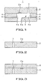
- a silicon (Si) substrate is provided as a substrate 2, as shown in Fig.2.
- an electro-thermal transducing device as an emission energy generating device 2a.
- an ink supply orifice 7 for supplying the ink i from an ink cartridge to an ink flow duct 3.
- a resin layer 8 On the surface of the substrate 2, carrying the emission energy generating device 2a, there is formed a resin layer 8 to a thickness of, for example, ca. 12 ⁇ m, by a semiconductor manufacture process, as shown in Fig.3.
- This resin layer 8 is formed of a flow duct forming material including an oxetane resin composition that contains, as necessary components, an oxetane compound having at least one oxetanyl group in a molecule, and a cationic photopolymerization initiator.
- the resin layer 8 is then irradiated with activation energy rays 10, such as ultraviolet light (UV light), through a patterned mask 9 so that the activation energy rays 10 will not be illuminated on the ink flow duct forming site, for effecting light exposure with the activation energy rays 10, as shown in Fig.4.
- activation energy rays 10 such as ultraviolet light (UV light)
- UV light ultraviolet light
- the exposed portion of the resin layer 8 is cured and becomes insoluble in the developing solution, while its unexposed portion becomes soluble in the developing solution.
- the unexposed portion of the resin layer 8 is then developed with a preset developing solution, not shown, to remove the unexposed portion of the resin layer 8, as shown in Fig.5.
- the remaining portion of the resin layer 8 forms the flow duct forming member 4 having a flow duct wall section 4a forming a portion of the ink flow duct 3.
- the nozzle sheet 5 is bonded to the flow duct forming member 4, with the aid of pressure and heat in combination, as adjustment is made of the position relationship between the nozzle 5a and the emission energy generating device 2a.
- the pulse current is supplied to the emission energy generating device 2a to rapidly heat the emission energy generating device 2a, as shown in Figs.6A and 6B, an air bubble b is generated in the portion of the ink i contacted with the emission energy generating device 2a, as shown in Fig.6A.
- the air bubble b is expanded to pressurized the ink i, so that the ink i, thus pressurized, is ejected from the nozzle 5a as a liquid droplet, as shown in Fig.6B.
- the ink i is supplied from the ink supply orifice 7 into the ink flow duct 3 to resume the pre-emission state of the ink jet recording head 1.
- the ink jet recording head 1 in which an oxetane resin composition that contains, as necessary components, an oxetane compound having at least one oxetanyl group in a molecule, and a cationic photopolymerization initiator is used as a flow duct forming material, undergoes only little contraction, at the time of curing, such that high mechanical strength as well as high tenacity and elongation may be developed to assure high operational reliability.
- the head is cleaned, such that mechanical load is applied to the head surface, there is no risk that the flow duct forming member 4 peels off from the substrate 2 or undergoes cracking.
- the ink jet recording head 1 in which a flow duct forming material containing the oxetane resin composition is used as the flow duct forming member 4, is rendered water-proof and resistant against chemicals. Furthermore, since the flow duct forming material, formed of the oxetane resin composition, also contains an additive, tightness in affixture may be maintained between the substrate 2 and the flow duct forming member 4 even on contact with the ink i, thus assuring high operational reliability of the present ink jet recording head 1 for prolonged time.
- the flow duct forming member 4 may be elongated or increased in thickness, through the use of the flow duct forming material of the oxetane resin composition for the flow duct forming member 4.
- the ink flow duct 3 of complex or intricate structure may be formed with ease to high accuracy.
- electro-thermal transducers are used as the emission energy generating device 2a.
- an electro-mechanical transducing system employing an electro-mechanical transducing device, such as a piezo device, may also be used for ejecting the ink i from the nozzle.
- the present invention is applied to a printer.
- this is merely illustrative and the present invention may be applied to a large variety of other liquid ejecting devices, such as facsimile or copying devices.
- the following shows the results of researches into physical properties of the flow duct forming material, and the results of evaluation of the resistance against the ink and printing performance of the ink jet recording head, prepared with the use of the flow duct forming member.
- the following experiments were conducted for scrutinizing into the problem inherent in the resin, that is, the post-curing inner stress of the resin.
- the inner stress was checked by observing the pre-curing film thickness and the post-curing film thickness of the resin layer. If the two film thicknesses are equal, it may be presumed that the inner stress caused by volumetric changes accompanying the curing of the resin is extremely small.
- Example 1 a flow duct forming material containing an oxetane resin composition, shown in the following Table 1, was spin-coated on a 6-inch wafer. The resulting product was pre-baked on a hot plate at 90°C for five minutes. Coating was then made to a film thickness of 20 ⁇ m and exposed to light by a mirror projection light exposure device (MPA 600 FA manufactured by Canon Inc.) to 1J/ cm 2 . After post baking on a hot plate at 90°C for five minutes, the resulting product was cured at 200°C for one hour to produce a cured film of the oxetane resin composition.
- MPA 600 FA manufactured by Canon Inc.
- phenol novolak oxetane compound (average number of basic structures: 3) 100 parts by weight cationic photopolymerization initiator (SP-170 manufactured by Asahi Denka Kogyo K.K.) 2 parts by weight silane coupling agent (2-(3, 4 epoxy cyclohexyl) ethyl trimethoxysilane 0.5 part by weight organic solvent (petroleum naphtha: IPSOL150 manufactured by Idemitsu Kosan Co.,Ltd) 100 parts by weight
- SP-170 cationic photopolymerization initiator
- silane coupling agent (2-(3, 4 epoxy cyclohexyl) ethyl trimethoxysilane
- organic solvent (petroleum naphtha: IPSOL150 manufactured by Idemitsu Kosan Co.,Ltd) 100 parts by weight
- a cured film of an alycyclic epoxy resin composition was obtained in the same way as in Example 1, using a solution containing the alicyclic epoxy resin composition shown in the following Table 2.
- Table 2 alicyclic epoxy resin (EHPE-3150: DICEL CHEMICAL INDUSTRIES, LTD.) 100 parts by weight cationic photopolymerization initiator (SP-170 manufactured by Asahi Denka Kogyo K.K.) 2 parts by weight silane coupling agent (2-(3, 4 epoxy cyclohexyl) ethyl trimethoxysilane 0.5 part by weight organic solvent (xylene) 100 parts by weight
- Example 2 Of the cured films, obtained in Example 1 and in Comparative Example 1, film thicknesses after curing on a hot plate at 200°C for one hour were measured. The results of measurement indicated that, while the film thicknesses were not decreased with the cured films containing the oxetane resin composition shown in Table 1, the film thicknesses were decreased with the cured films containing the alicyclic epoxy resin composition shown in Table 2.
- the stress in the respective cured films was then measured, using a thin film stress measurement device. It was seen that the stress in the cured films containing the oxetane resin composition shown in Table 1 was decreased appreciably as compared to that in the cured films containing the alicyclic epoxy resin composition shown in Table 2.
- the ink jet recording head 1 was prepared in the following manner. Initially, a silicon (Si) substrate, on a preset area of which was formed an electro-thermal transducing device, as an emission energy generating device 2a, was provided as shown in Fig.2. In the substrate 2, there was formed an ink supply orifice 7 for supplying the ink i from an ink cartridge to the ink flow duct 3.
- Si silicon
- This resin layer 8 was formed of a flow duct forming material including an oxetane resin composition that contains, as necessary components, an oxetane compound having at least one oxetanyl group in a molecule, and a cationic photopolymerization initiator.
- the resin layer 8 was then irradiated with activation energy rays 10, such as ultraviolet light (UV light), through a patterned mask 9, so that the activation energy rays 10 will not be illuminated on the ink flow duct forming site, for effecting light exposure with the activation energy rays 10, as shown in Fig.4.
- activation energy rays 10 such as ultraviolet light (UV light)
- UV light ultraviolet light
- the exposed portion of the resin layer 8 was cured and turned insoluble in the developing solution, while its unexposed portion was turned soluble in the developing solution.
- the unexposed portion of the resin layer 8 was then developed with a preset developing solution, not shown, to remove the unexposed portion of the resin layer 8, as shown in Fig.5.
- the remaining portion of the resin layer 8 formed the flow duct forming member 4 having the flow duct wall section 4a forming a portion of the ink flow duct 3.
- the nozzle sheet 5 was affixed to the flow duct forming member 4, with the aid of pressure and heat in combination, as adjustment was made of the position relationship between the nozzle 5a and the emission energy generating device 2a.
- an ink jet recording head 1 was prepared in which there was formed an ink flow duct 3 delimited by the substrate 2, flow duct forming member 4 and the nozzle sheet 5.
- an ink jet recording head 1 was prepared in the same way as in Example 1, except using, as a material of the flow duct forming member 4 forming the ink duct, a flow duct forming material containing the alicyclic epoxy resin composition shown in Table 2.
- the ink jet recording heads 1 of the Example 2 and the Comparative Example 2 were immersed in black ink at 60°C for one week by way of an ink immersion test.
- black ink an ink composed of pure water, ethylene glycol and black dye, manufactured by Sony Corporation for LPR-5000, was used.
- the ink flow duct 3 of high durability could be produced in which the inner stress and exfoliation from the substrate 2 could be reduced based upon characteristics of the flow duct forming material as a low stress material proper to the oxetane resin. From this it may be seen that an ink jet recording head which may exhibit high operational reliability for prolonged time may be produced with the use of the flow duct forming member 4 formed of this flow duct forming material.
Applications Claiming Priority (1)
| Application Number | Priority Date | Filing Date | Title |
|---|---|---|---|
| JP2005229865A JP4702784B2 (ja) | 2005-08-08 | 2005-08-08 | 液体吐出型記録ヘッドの流路構成材料 |
Publications (2)
| Publication Number | Publication Date |
|---|---|
| EP1752297A2 true EP1752297A2 (fr) | 2007-02-14 |
| EP1752297A3 EP1752297A3 (fr) | 2008-08-20 |
Family
ID=37401019
Family Applications (1)
| Application Number | Title | Priority Date | Filing Date |
|---|---|---|---|
| EP06016153A Withdrawn EP1752297A3 (fr) | 2005-08-08 | 2006-08-02 | Méthode de fabrication d'une tête d'impression à jet de liquide |
Country Status (4)
| Country | Link |
|---|---|
| US (2) | US20070032582A1 (fr) |
| EP (1) | EP1752297A3 (fr) |
| JP (1) | JP4702784B2 (fr) |
| CN (1) | CN1979337B (fr) |
Families Citing this family (1)
| Publication number | Priority date | Publication date | Assignee | Title |
|---|---|---|---|---|
| JP5105446B2 (ja) * | 2009-07-13 | 2012-12-26 | 太陽ホールディングス株式会社 | 樹脂構造体及びその製造方法 |
Citations (6)
| Publication number | Priority date | Publication date | Assignee | Title |
|---|---|---|---|---|
| EP1138739A1 (fr) * | 1999-08-12 | 2001-10-04 | Mitsui Chemicals, Inc. | Composition de resine photodurcissable pour materiau d'etancheite et procede correspondant |
| US20020161068A1 (en) | 2000-04-28 | 2002-10-31 | Takeo Watanabe | Polymerizable composition, cured material thereof and method for manufacturing the same |
| EP1302499A2 (fr) | 2001-09-28 | 2003-04-16 | Brother Kogyo Kabushiki Kaisha | Composition durcissable par rayonnement, encre contenant cette composition et imprimante contenant cette encre |
| US20050004662A1 (en) | 1998-09-05 | 2005-01-06 | Abbott Laboratories Vascular Enterprises Limited | Methods and apparatus for a drug-coated stent having an expandable web structure |
| WO2006078069A2 (fr) | 2005-01-21 | 2006-07-27 | Canon Kabushiki Kaisha | Tete d'impression a jet d'encre, procede de fabrication correspondant et composition pour tete d'impression a jet d'encre |
| EP1729175A1 (fr) | 2004-03-26 | 2006-12-06 | Tokyo Ohka Kogyo Co., Ltd. | Composition à base de résine photosensible et procédé de formation d' un modèle avec la composition |
Family Cites Families (16)
| Publication number | Priority date | Publication date | Assignee | Title |
|---|---|---|---|---|
| JP3765896B2 (ja) * | 1996-12-13 | 2006-04-12 | Jsr株式会社 | 光学的立体造形用光硬化性樹脂組成物 |
| JP2000336133A (ja) * | 1999-05-27 | 2000-12-05 | Ube Ind Ltd | 新規なオキセタンスルフォン酸エステルおよびそれを用いたオキセタン化ノボラック樹脂ならびにその製造法 |
| US6255484B1 (en) * | 1999-09-28 | 2001-07-03 | Ube Industries, Ltd. | Cyanurate compound having three oxetane ring groups and organic hardening compositions containing same |
| JP2001329050A (ja) * | 2000-05-23 | 2001-11-27 | Nippon Kayaku Co Ltd | 光カチオン硬化型樹脂組成物並びにその硬化物 |
| JP2001351717A (ja) * | 2000-06-08 | 2001-12-21 | Sumitomo Wiring Syst Ltd | コネクタ |
| EP1502155B1 (fr) * | 2002-05-03 | 2013-01-30 | DSM IP Assets B.V. | Composition de resine durcissable par irradiation et procede de prototypage rapide faisant appel a celle-ci |
| JP2004359715A (ja) * | 2003-06-02 | 2004-12-24 | Konica Minolta Medical & Graphic Inc | 光硬化型インク並びにこれを用いる画像記録装置及び画像記録方法 |
| ATE551195T1 (de) * | 2003-07-22 | 2012-04-15 | Canon Kk | Tintenstrahlkopf und dazugehöriges herstellungsverfahren |
| EP1661930A4 (fr) * | 2003-08-12 | 2010-09-29 | Mitsui Chemicals Inc | Composition de resine photodurcissable et agent de scellement pour afficheur a panneau plat utilisant cette composition |
| JP2005074747A (ja) * | 2003-08-29 | 2005-03-24 | Canon Inc | インクジェットヘッドの製造方法およびインクジェットヘッド |
| TW200533692A (en) * | 2003-11-06 | 2005-10-16 | Showa Denko Kk | Curable polyester having an oxetanyl group at end and process for preparing the same, resist composition, jet printing ink composition, curing methods and uses thereof |
| JP4667028B2 (ja) * | 2004-12-09 | 2011-04-06 | キヤノン株式会社 | 構造体の形成方法及びインクジェット記録ヘッドの製造方法 |
| JP4713269B2 (ja) * | 2005-08-08 | 2011-06-29 | ソニー株式会社 | 液体吐出型記録ヘッドの製造方法 |
| JP4470835B2 (ja) * | 2005-08-08 | 2010-06-02 | ソニー株式会社 | 液体吐出型記録ヘッド及び液体吐出装置 |
| KR100717028B1 (ko) * | 2005-09-13 | 2007-05-10 | 삼성전자주식회사 | 전도성 에폭시 수지를 구비한 잉크젯 프린터 헤드 |
| KR100837409B1 (ko) * | 2006-11-30 | 2008-06-12 | 삼성전자주식회사 | 옥세탄-함유 화합물, 이를 포함한 포토레지스트 조성물,상기 포토레지스트 조성물을 이용한 패턴 형성 방법 및잉크젯 프린트 헤드 |
-
2005
- 2005-08-08 JP JP2005229865A patent/JP4702784B2/ja not_active Expired - Fee Related
-
2006
- 2006-07-27 US US11/460,336 patent/US20070032582A1/en not_active Abandoned
- 2006-08-02 EP EP06016153A patent/EP1752297A3/fr not_active Withdrawn
- 2006-08-08 CN CN200610146389.6A patent/CN1979337B/zh not_active Expired - Fee Related
-
2011
- 2011-11-14 US US13/295,329 patent/US20120056950A1/en not_active Abandoned
Patent Citations (6)
| Publication number | Priority date | Publication date | Assignee | Title |
|---|---|---|---|---|
| US20050004662A1 (en) | 1998-09-05 | 2005-01-06 | Abbott Laboratories Vascular Enterprises Limited | Methods and apparatus for a drug-coated stent having an expandable web structure |
| EP1138739A1 (fr) * | 1999-08-12 | 2001-10-04 | Mitsui Chemicals, Inc. | Composition de resine photodurcissable pour materiau d'etancheite et procede correspondant |
| US20020161068A1 (en) | 2000-04-28 | 2002-10-31 | Takeo Watanabe | Polymerizable composition, cured material thereof and method for manufacturing the same |
| EP1302499A2 (fr) | 2001-09-28 | 2003-04-16 | Brother Kogyo Kabushiki Kaisha | Composition durcissable par rayonnement, encre contenant cette composition et imprimante contenant cette encre |
| EP1729175A1 (fr) | 2004-03-26 | 2006-12-06 | Tokyo Ohka Kogyo Co., Ltd. | Composition à base de résine photosensible et procédé de formation d' un modèle avec la composition |
| WO2006078069A2 (fr) | 2005-01-21 | 2006-07-27 | Canon Kabushiki Kaisha | Tete d'impression a jet d'encre, procede de fabrication correspondant et composition pour tete d'impression a jet d'encre |
Also Published As
| Publication number | Publication date |
|---|---|
| CN1979337A (zh) | 2007-06-13 |
| JP4702784B2 (ja) | 2011-06-15 |
| US20070032582A1 (en) | 2007-02-08 |
| EP1752297A3 (fr) | 2008-08-20 |
| JP2007044926A (ja) | 2007-02-22 |
| US20120056950A1 (en) | 2012-03-08 |
| CN1979337B (zh) | 2012-01-11 |
Similar Documents
| Publication | Publication Date | Title |
|---|---|---|
| JP5279476B2 (ja) | 液体吐出ヘッドの製造方法 | |
| CN1968815B (zh) | 排液头制造方法,和使用该方法得到的排液头 | |
| EP1763440B1 (fr) | Procédé de fabrication de tête à jet d'encre et tête à jet d'encre fabriquée selon le procédé de fabrication | |
| KR100823746B1 (ko) | 수지 조성물, 수지 경화물 및 액체 토출 헤드 | |
| US20070081048A1 (en) | Photosensitive resin composition, ink jet head using photosensitive resin composition, and process for manufacturing ink jet head | |
| US7472480B2 (en) | Method for producing liquid ejecting recording head | |
| US8197033B2 (en) | Ink jet cartridge comprising a layer made by a curable resin composition | |
| US9050806B2 (en) | Liquid ejection head | |
| JP2017121787A (ja) | 基材上に部分撥液領域を形成する方法 | |
| US7665827B2 (en) | Liquid discharge recording head having an improved oxetane resin covering layer as part of a liquid flow path and liquid discharge apparatus | |
| KR100560720B1 (ko) | 광경화성 수지 조성물을 사용한 잉크젯 프린트 헤드의제조방법 | |
| US9776411B2 (en) | Inkjet recording head and method of manufacturing the same | |
| JP3986060B2 (ja) | インクジェット記録ヘッドの流路構成部材及びインクジェット記録ヘッドの製造方法 | |
| EP1752297A2 (fr) | Méthode de fabrication d'une tête d'impression à jet de liquide | |
| US11433674B2 (en) | Liquid discharge head and method for producing liquid discharge head | |
| CN101746141B (zh) | 液体排出头的制造方法 | |
| JP4965986B2 (ja) | エポキシ樹脂組成物、樹脂硬化物および液体吐出ヘッド。 | |
| KR101320780B1 (ko) | 액체 토출형 기록 헤드 및 액체 토출 장치 | |
| KR20070017917A (ko) | 액체 토출 기록 헤드의 제조 방법 | |
| KR20070017916A (ko) | 액체 토출 기록 헤드의 제조 방법 | |
| US10618287B2 (en) | Liquid ejection head, method for manufacturing the same, and recording method | |
| JP4908816B2 (ja) | インクジェットヘッドの製造方法 | |
| KR20070022805A (ko) | 액체 토출 헤드 제조 방법, 및 이러한 방법을 사용하여얻어지는 액체 토출 헤드 | |
| JP2018161810A (ja) | 液体吐出ヘッドの製造方法 |
Legal Events
| Date | Code | Title | Description |
|---|---|---|---|
| PUAI | Public reference made under article 153(3) epc to a published international application that has entered the european phase |
Free format text: ORIGINAL CODE: 0009012 |
|
| AK | Designated contracting states |
Kind code of ref document: A2 Designated state(s): AT BE BG CH CY CZ DE DK EE ES FI FR GB GR HU IE IS IT LI LT LU LV MC NL PL PT RO SE SI SK TR |
|
| AX | Request for extension of the european patent |
Extension state: AL BA HR MK YU |
|
| PUAL | Search report despatched |
Free format text: ORIGINAL CODE: 0009013 |
|
| AK | Designated contracting states |
Kind code of ref document: A3 Designated state(s): AT BE BG CH CY CZ DE DK EE ES FI FR GB GR HU IE IS IT LI LT LU LV MC NL PL PT RO SE SI SK TR |
|
| AX | Request for extension of the european patent |
Extension state: AL BA HR MK RS |
|
| 17P | Request for examination filed |
Effective date: 20090220 |
|
| AKX | Designation fees paid |
Designated state(s): DE FR GB |
|
| 17Q | First examination report despatched |
Effective date: 20101223 |
|
| GRAJ | Information related to disapproval of communication of intention to grant by the applicant or resumption of examination proceedings by the epo deleted |
Free format text: ORIGINAL CODE: EPIDOSDIGR1 |
|
| GRAP | Despatch of communication of intention to grant a patent |
Free format text: ORIGINAL CODE: EPIDOSNIGR1 |
|
| RIN1 | Information on inventor provided before grant (corrected) |
Inventor name: KOHNO, MINORU, C/O SONY CORP. Inventor name: ONO, SHOGO, C/O SONY CORP. Inventor name: TOMITA, MANABU, C/O SONY CORP. Inventor name: IGARASHI, KOICHI, C/O SONY CORP. Inventor name: MAKITA, SHOHEI, C/O RANZAN FACILITY, Inventor name: USHIKI, SHIGERU, C/O RANZAN FACILITY, |
|
| INTG | Intention to grant announced |
Effective date: 20130326 |
|
| RIN1 | Information on inventor provided before grant (corrected) |
Inventor name: ONO, SHOGO, C/O SONY CORPORATION Inventor name: TOMITA, MANABU, C/O SONY CORPORATION Inventor name: IGARASHI, KOICHI, C/O SONY CORPORATION Inventor name: USHIKI, SHIGERU, C/O RANZAN FACILITY, Inventor name: MAKITA, SHOHEI, C/O RANZAN FACILITY, Inventor name: KOHNO, MINORU, C/O SONY CORPORATION |
|
| STAA | Information on the status of an ep patent application or granted ep patent |
Free format text: STATUS: THE APPLICATION IS DEEMED TO BE WITHDRAWN |
|
| 18D | Application deemed to be withdrawn |
Effective date: 20130806 |