EP1750954B1 - Pneumatique pour vehicules lourds - Google Patents
Pneumatique pour vehicules lourds Download PDFInfo
- Publication number
- EP1750954B1 EP1750954B1 EP05745596A EP05745596A EP1750954B1 EP 1750954 B1 EP1750954 B1 EP 1750954B1 EP 05745596 A EP05745596 A EP 05745596A EP 05745596 A EP05745596 A EP 05745596A EP 1750954 B1 EP1750954 B1 EP 1750954B1
- Authority
- EP
- European Patent Office
- Prior art keywords
- ply
- reinforcement
- reinforcement elements
- tyre
- radially
- Prior art date
- Legal status (The legal status is an assumption and is not a legal conclusion. Google has not performed a legal analysis and makes no representation as to the accuracy of the status listed.)
- Expired - Lifetime
Links
Images


Classifications
-
- B—PERFORMING OPERATIONS; TRANSPORTING
- B60—VEHICLES IN GENERAL
- B60C—VEHICLE TYRES; TYRE INFLATION; TYRE CHANGING; CONNECTING VALVES TO INFLATABLE ELASTIC BODIES IN GENERAL; DEVICES OR ARRANGEMENTS RELATED TO TYRES
- B60C9/00—Reinforcements or ply arrangement of pneumatic tyres
- B60C9/18—Structure or arrangement of belts or breakers, crown-reinforcing or cushioning layers
- B60C9/26—Folded plies
-
- B—PERFORMING OPERATIONS; TRANSPORTING
- B60—VEHICLES IN GENERAL
- B60C—VEHICLE TYRES; TYRE INFLATION; TYRE CHANGING; CONNECTING VALVES TO INFLATABLE ELASTIC BODIES IN GENERAL; DEVICES OR ARRANGEMENTS RELATED TO TYRES
- B60C9/00—Reinforcements or ply arrangement of pneumatic tyres
- B60C9/18—Structure or arrangement of belts or breakers, crown-reinforcing or cushioning layers
- B60C9/20—Structure or arrangement of belts or breakers, crown-reinforcing or cushioning layers built-up from rubberised plies each having all cords arranged substantially parallel
- B60C9/2003—Structure or arrangement of belts or breakers, crown-reinforcing or cushioning layers built-up from rubberised plies each having all cords arranged substantially parallel characterised by the materials of the belt cords
- B60C9/2006—Structure or arrangement of belts or breakers, crown-reinforcing or cushioning layers built-up from rubberised plies each having all cords arranged substantially parallel characterised by the materials of the belt cords consisting of steel cord plies only
-
- B—PERFORMING OPERATIONS; TRANSPORTING
- B60—VEHICLES IN GENERAL
- B60C—VEHICLE TYRES; TYRE INFLATION; TYRE CHANGING; CONNECTING VALVES TO INFLATABLE ELASTIC BODIES IN GENERAL; DEVICES OR ARRANGEMENTS RELATED TO TYRES
- B60C9/00—Reinforcements or ply arrangement of pneumatic tyres
- B60C9/18—Structure or arrangement of belts or breakers, crown-reinforcing or cushioning layers
- B60C9/20—Structure or arrangement of belts or breakers, crown-reinforcing or cushioning layers built-up from rubberised plies each having all cords arranged substantially parallel
- B60C9/22—Structure or arrangement of belts or breakers, crown-reinforcing or cushioning layers built-up from rubberised plies each having all cords arranged substantially parallel the plies being arranged with all cords disposed along the circumference of the tyre
-
- Y—GENERAL TAGGING OF NEW TECHNOLOGICAL DEVELOPMENTS; GENERAL TAGGING OF CROSS-SECTIONAL TECHNOLOGIES SPANNING OVER SEVERAL SECTIONS OF THE IPC; TECHNICAL SUBJECTS COVERED BY FORMER USPC CROSS-REFERENCE ART COLLECTIONS [XRACs] AND DIGESTS
- Y10—TECHNICAL SUBJECTS COVERED BY FORMER USPC
- Y10T—TECHNICAL SUBJECTS COVERED BY FORMER US CLASSIFICATION
- Y10T152/00—Resilient tires and wheels
- Y10T152/10—Tires, resilient
- Y10T152/10495—Pneumatic tire or inner tube
- Y10T152/10765—Characterized by belt or breaker structure
- Y10T152/10792—Structure where each bias angle reinforcing cord ply has no opposingly angled ply
Definitions
- the present invention relates to a tire with a radial carcass reinforcement anchored on both sides to at least one bead wire and having a crown reinforcement consisting of at least two so-called working layers superimposed and formed of parallel wires or cables. in each ply and crossed from one ply to the next, making with the circumferential direction of the tire angles at most equal to 45 ° in absolute value.
- It relates more particularly to a tire of the "Heavy Truck” type, whose ratio of the height on rim H over its maximum axial width S is at most equal to 0.80, and intended to equip a vehicle of medium or large tonnage, such as as truck, bus, trailer, etc.
- Some current tires are intended to run at high speed and on longer and longer journeys, because of the improvement of the road network and the growth of the motorway network in the world.
- the set of conditions under which such a tire is called to roll undoubtedly allows an increase in the number of kilometers traveled, the wear of the tire being less; against the endurance of the latter and in particular of the crown reinforcement is penalized.
- crown reinforcement the first deficiency being strongly influenced by the operating temperature prevailing at the borders of the working plies, whether in straight-line running or drifting.
- a first solution has been described in the patent application WO-A-96/20095 and proposes, on the one hand, between the carcass reinforcement and the crown reinforcement working ply, radially closest to the axis of rotation, an axially continuous ply formed of non-extensible metal cords circumferential direction an angle at least equal to 60 °, and whose axial width is at least equal to the axial width of the shortest working crown ply, and secondly between the two working crown plies a additional ply formed of metal elements, oriented substantially parallel to the circumferential direction, the axial width of said ply being at least 0.7 S0.
- the patent application WO-A-99/58351 proposes, together with an additional ply whose orientation of the reinforcing elements is radial, a coupling of the two working crown plies in the immediate axial extension of the additional ply and then being decoupled by at least one rubber compounding profile on the remainder of the width common to said two working plies.
- an additional reinforcement formed of at least one ply of reinforcing elements, arranged radially between two working plies, is axially composed of three parts, a central portion in the form of a ply formed of reinforcing elements. inextensible and substantially radial metal, and two lateral portions in the form of strips each formed of elastic circumferential metal reinforcing elements.
- the patent US Patent 5,277,239 discloses a tire for automobile comprising two working plies of reinforcement elements with a high modulus of elasticity in which the ends of a first working ply are turned over to cover the ends of the other working ply, said tire comprising still shoulder plies of circumferential reinforcing elements.
- FR-A-1,228,241 discloses a tire which may comprise three plies, at least one of which has its ends folded in order to promote the cooling of the constituents of the armature.
- Cables are said to be elastic when said cables have under a tensile force equal to the breaking load a relative elongation of at least 4%.
- the circumferential direction of the tire is the direction corresponding to the periphery of the tire and defined by the rolling direction of the tire.
- Circumferential reinforcing elements are elements which make angles with said direction in the range + 2.5 °, - 2.5 ° around 0 °.
- the transverse or axial direction of the tire is parallel to the axis of rotation of the tire.
- the radial direction is a direction intersecting the axis of rotation of the tire and perpendicular to it.
- Substantially radial reinforcing elements are elements which make with the meridian direction angles in the range + 5 °, - 5 ° around 0 °.
- the axis of rotation of the tire is the axis around which it rotates under normal use.
- a radial or meridian plane is a plane which contains the axis of rotation of the tire.
- the circumferential median plane is a plane perpendicular to the axis of rotation of the tire and which divides the tire into two halves.
- the inventors have given themselves the task of supplying tires for "heavy-weight" vehicles whose endurance performance is further improved compared with conventional tires.
- a tire for vehicles of the Heavy Truck type, having a radial carcass reinforcement comprising a crown reinforcement formed of at least two working crown plies of reinforcement elements, crossed by a ply to the other by making with the circumferential direction angles between 10 ° and 45 °, itself capped radially of a tread, said tread being joined to two beads by means of two flanks, the crown reinforcement comprising, between two working crown plies, at least one ply of additional reinforcing elements, the axial ends of the reinforcement element working ply radially closest to the carcass reinforcement being returned for covering the axial ends of a working crown ply radially external to the ply additional, said strengthening elements of the reinforcing ply web radially closest to the carcass reinforcement being elastic.
- a heavy weight type of tire thus produced leads to quite satisfactory wear properties and furthermore, it appears that the endurance of such a tire is further improved; the turning of the radially inner working ply contributes to the improvement of the endurance of the tire, the influence of the free ends of the working plies being substantially reduced.
- said reinforcing elements of the reinforcement element ply radially closest to the carcass reinforcement being elastic, leads in particular to a simple tire manufacturing process and provides other advantages over which it will be returned later, depending on the embodiment of the crown reinforcement.
- the axial ends of the reinforcement element ply radially closest to the carcass reinforcement cover the axial ends of the radially outermost working crown ply.
- no end of said plies is left free.
- An advantageous embodiment of the invention provides that the axial ends of the reinforcement element ply radially closest to the carcass reinforcement are axially internal to the axial ends of the ply of additional reinforcing elements. According to this advantageous embodiment of the invention, the returned ends of the reinforcement element ply radially closest to the carcass reinforcement radially cover the ends of the additional ply for better endurance of the crown reinforcement and in particular of said additional ply.
- the layer of circumferential reinforcing elements is advantageously a continuous layer over its entire axial width.
- the additional ply consists of at least two lateral portions in the form of strips each formed of circumferential reinforcing elements.
- the additional ply further comprises a central portion formed of a ply consisting of substantially radial reinforcement elements.
- a sheet also contributes to the reduction of shearing stresses between the working layers and thus further improves performance. endurance of the tire in particular by limiting the temperature increases of the rubbery mass.
- a better stiffness of the shoulders of the tire is observed, which is favorable to a reduction in the risks of irregular wear of the tread which increases when the tire aspect ratio decreases.
- the embodiment of the tire comprising a reversal of the ends of the radially innermost working ply, also makes it possible to contribute to the rigidity of the reinforcing reinforcement in the axially outer zones of the tire and thus to to improve the endurance of circumferential reinforcing elements, particularly sensitive in these zones.
- the reinforcing elements of the ply of circumferential reinforcing elements are metal reinforcing elements having a secant modulus at 0.7% elongation between 10 and 120 GPa and a maximum tangent modulus less than 150 GPa.
- the secant modulus of the reinforcing elements at 0.7% elongation is less than 100 Gpa, preferably greater than 50 GPa and more preferably between 60 and 90 GPa.
- the maximum tangent modulus of the reinforcing elements is less than 130 GPa.
- the secant modulus is measured on a tensile stress curve as a function of the elongation determined with a preload less than 5 kg.
- the reinforcing elements of the ply of circumferential reinforcing elements are metal reinforcing elements having a tensile stress curve as a function of the relative elongation having small slopes for the low elongations and a slope. substantially constant and strong for the higher elongations.
- Such reinforcing elements of the web of circumferential reinforcing elements are usually referred to as "bi-module" elements.
- the substantially constant and strong slope appears from a relative elongation of between 0.2% and 0.8%.
- Reinforcing elements that are more particularly suitable for producing the ply of circumferential reinforcing elements according to the invention are, for example, assemblies of formula 21.23; this strand cable consists of 21 elementary wires of diameter equal to 23/100 mm and of formula 3 x (1 + 6), with 3 strands, consisting of 7 son, one forming a central core, and twisted together.
- another example of reinforcing elements is an assembly of formula 21.28.
- reinforcing elements in at least one ply of circumferential reinforcing elements makes it possible in particular to maintain satisfactory rigidity of the ply, including after the conformation and firing steps in usual manufacturing processes.
- the circumferential reinforcing elements may be formed of inextensible metal elements and cut so as to form sections of length much shorter than the circumference of the shorter layer, but preferably greater than 0.1 times said circumference, the cuts between sections being axially offset with respect to each other. More preferably, the tensile modulus of elasticity per unit width of the additional ply is less than the modulus of tensile elasticity, measured under the same conditions, of the most extensible working crown ply.
- Such an embodiment makes it possible to confer, in a simple manner, on the ply of circumferential reinforcement elements a module that can easily be adjusted (by the choice of intervals between sections of the same row), but in all cases weaker. that the modulus of the web consisting of the same metal elements but continuous, the module of the additional web being measured on a vulcanized web of cut elements, taken from the tire.
- the circumferential reinforcing elements are corrugated metal elements, the ratio a / ⁇ of the amplitude of waviness at the wavelength being at most equal to 0.09.
- the tensile modulus of elasticity per unit width of the additional ply is less than the tensile modulus of elasticity, measured under the same conditions, of the most extensible working crown ply.
- the metal elements are preferably steel cables.
- the axial widths of the working crown plies radially adjacent to an additional ply of circumferential reinforcement elements are greater than the axial width of said additional ply and preferably, said working crown plies adjacent to the additional ply are of both sides of the equatorial plane and in the immediate axial extension of the additional ply coupled over an axial width, in particular when the working ply turned at its ends is not adjacent to said additional ply.
- Coupled plies means plies whose respective reinforcing elements are radially separated by at most 1.5 mm, said rubber thickness being measured radially between the respectively upper and lower generatrices of said reinforcing elements.
- the invention further advantageously provides for decreasing the voltage stresses acting on the axially outermost circumferential members that the angle formed with the circumferential direction by the reinforcing elements of the working crown layers is less than 30 ° and preferably less than 25 °.
- the working crown layers comprise reinforcing elements, crossed from one ply to the other, making with the circumferential direction variable angles in the axial direction, said angles being greater on the axially outer edges of the reinforcing element layers with respect to the angles of said elements measured at the circumferential mid-plane.
- a preferred embodiment of the invention further provides that the crown reinforcement is completed radially on the outside by at least one additional layer, called protection, said elastic reinforcing elements, oriented relative to the circumferential direction with an angle of between 10 ° and 45 ° and in the same direction as the angle formed by the inextensible elements of the working layer which is radially adjacent thereto .
- the protective ply covers the turned ends of the radially inner working ply, in particular when these are radially external to the radially outermost working ply.
- the protective ply is positioned axially between the turned ends of the radially inner working ply, and advantageously its axial ends are contiguous, or axially juxtaposed, with the turned ends of the working ply. radially inner, especially when they are radially external to the radially outermost working ply.
- the returned ends of the radially inner working ply are radially external to the protective ply, and preferably cover the ends of said ply.
- An alternative embodiment of the invention according to which the reinforcement elements of the radially inner working ply are elastic, provides that the inverted portions of said radially inner working ply have a function similar to that of a protective ply, especially when said reinforcement elements returned are not crossed with the elements of the reinforcement ply which is radially adjacent thereto.
- the reinforcing elements of the radially inner working ply and the elements of the radially outer working ply have opposite angles of the same value.
- a complementary protective layer is no longer useful.
- the crown reinforcement can be further completed, radially inwardly between the carcass reinforcement and the radially inner working layer closest to said carcass reinforcement. by a triangulation layer of steel non-extensible reinforcing elements making, with the circumferential direction, an angle greater than 50 ° in absolute value.
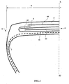
- the crown reinforcement is itself capped with a tread 5.
- the working ply 41 is turned over and its ends 6 are arranged radially outside the working ply 43 and radially adjacent thereto.
- the turned ends 6 of the working ply 41 are radially covered by the protective ply 44.
- the inversion of the working ply 41 makes it possible to eliminate the free ends of the working plies and to limit the movements of these ends during rolling while increasing the stiffnesses at the shoulders of the tire.
- the ply 42 of circumferential reinforcement elements in turn contributes to the improvement in particular of the wear resistance of the tire, in association with the upset of the working ply 41, due to the increase in stiffness. It further improves the stability of the crown of the tire during inflation.
- the reversals of the working ply 41 covers the ends of said ply 42 of circumferential reinforcing elements over a width L and thus improves the endurance of these circumferential reinforcement elements, in particular because of the participation of the parts returned from the working ply 41 at the rigidity of the reinforcement, in particular in the axially extreme portions of the ply 42.
- the lap width L is advantageously greater than four times the pitch of the circumferential reinforcement elements of the ply 42.
- the sheet 42 is in the example described a continuous sheet of circumferential reinforcing elements but could also be constituted, in accordance with the invention, two plies of circumferential reinforcing elements narrower, axially distant one of the other and advantageously put in place substantially at the shoulders of the tire. These two plies of circumferential reinforcement elements may further be axially separated by a ply of radially oriented reinforcing elements.
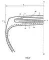
- the tire 1 differs from that shown on the figure 1 in that the protective ply 44 is axially interposed between the ends 6 of the turns of the working ply 41.
- Such an embodiment makes it possible in particular to limit the thickness of the crown reinforcement, in particular with respect to the case of the figure 1 .
- the tire 1 differs from those shown in the preceding figures in that it does not include a protective layer.
- the turns of the working ply 41 are axially extended and the ends 6 are axially contiguous with each other.
- the turns of the working ply 41 thus functionally replace a protective ply.
- the angles of the two working plies 41, 43 are identical in absolute value, so that the protection function performed by the turns of the working ply 41 is optimal.
- the tire 1 is an embodiment variant of that represented on the figure 1 according to which the crown reinforcement comprises a triangulation ply 7 interposed radially between the carcass reinforcement and the working ply 41.
- the triangulation ply 7 is formed of 11x35 unstretchable, inextensible metal ropes oriented at an equal angle at 50 °, said metal cables being crossed with the reinforcing elements of the ply 41.
- This reference tire therefore does not include a reversal of the rib reinforcement working sheet radially closest to the carcass reinforcement.
- the tests carried out consisted of tests of destructive rolling on a steering wheel; this type of steering wheel test simulates circuit tests either in a straight line or with strong drift.
Landscapes
- Engineering & Computer Science (AREA)
- Mechanical Engineering (AREA)
- Tires In General (AREA)
- Transition And Organic Metals Composition Catalysts For Addition Polymerization (AREA)
- Organic Low-Molecular-Weight Compounds And Preparation Thereof (AREA)
- Carbon And Carbon Compounds (AREA)
Priority Applications (1)
| Application Number | Priority Date | Filing Date | Title |
|---|---|---|---|
| PL05745596T PL1750954T3 (pl) | 2004-05-13 | 2005-05-06 | Opona do samochodów ciężarowych |
Applications Claiming Priority (2)
| Application Number | Priority Date | Filing Date | Title |
|---|---|---|---|
| FR0405243A FR2870163B1 (fr) | 2004-05-13 | 2004-05-13 | Pneumatique pour vehicules lourds |
| PCT/EP2005/004928 WO2005113258A1 (fr) | 2004-05-13 | 2005-05-06 | Pneumatique pour vehicules lourds |
Publications (2)
| Publication Number | Publication Date |
|---|---|
| EP1750954A1 EP1750954A1 (fr) | 2007-02-14 |
| EP1750954B1 true EP1750954B1 (fr) | 2008-04-23 |
Family
ID=34946146
Family Applications (1)
| Application Number | Title | Priority Date | Filing Date |
|---|---|---|---|
| EP05745596A Expired - Lifetime EP1750954B1 (fr) | 2004-05-13 | 2005-05-06 | Pneumatique pour vehicules lourds |
Country Status (10)
| Country | Link |
|---|---|
| US (1) | US8555942B2 (enExample) |
| EP (1) | EP1750954B1 (enExample) |
| JP (1) | JP4813466B2 (enExample) |
| CN (1) | CN100540341C (enExample) |
| AT (1) | ATE393036T1 (enExample) |
| BR (1) | BRPI0510968A (enExample) |
| DE (1) | DE602005006272T2 (enExample) |
| FR (1) | FR2870163B1 (enExample) |
| PL (1) | PL1750954T3 (enExample) |
| WO (1) | WO2005113258A1 (enExample) |
Families Citing this family (16)
| Publication number | Priority date | Publication date | Assignee | Title |
|---|---|---|---|---|
| DE102006037114A1 (de) | 2006-08-07 | 2008-02-14 | Continental Aktiengesellschaft | Fahrzeugluftreifen für Schwerlastfahrzeug |
| DE102007054534A1 (de) * | 2007-11-15 | 2009-05-20 | Continental Aktiengesellschaft | Fahrzeugluftreifen |
| FR2935297B1 (fr) | 2008-09-02 | 2010-09-03 | Michelin Soc Tech | Pneumatique pour vehicules lourds comportant au moins deux couches additionnelles dans les bourrelets |
| US9168789B2 (en) | 2008-12-19 | 2015-10-27 | The Goodyear Tire & Rubber Company | Truck tire |
| DE102009026182B4 (de) | 2009-07-16 | 2024-05-02 | Continental Reifen Deutschland Gmbh | Fahrzeugluftreifen |
| FR3000918B1 (fr) * | 2013-01-11 | 2015-01-30 | Michelin & Cie | Pneumatique comportant une couche d'elements de renforcement dont les extremites sont retournees |
| FR3000919B1 (fr) * | 2013-01-11 | 2015-01-30 | Michelin & Cie | Pneumatique comportant une armature sommet allegee |
| JP6159605B2 (ja) * | 2013-07-10 | 2017-07-05 | 住友ゴム工業株式会社 | タイヤ評価方法 |
| FR3008348B1 (fr) | 2013-07-12 | 2015-08-07 | Michelin & Cie | Pneumatique comportant des epaisseurs variables des melanges caoutchouteux interieurs a l'armature de carcasse |
| FR3008347B1 (fr) * | 2013-07-12 | 2015-08-07 | Michelin & Cie | Pneumatique comportant une armature de carcasse assouplie |
| FR3008346B1 (fr) | 2013-07-12 | 2015-08-07 | Michelin & Cie | Pneumatique comportant des cables d'armatures de carcasse presentant une faible permeabilite |
| CN104385855B (zh) * | 2014-10-15 | 2016-12-07 | 厦门正新橡胶工业有限公司 | 一种充气轮胎缓冲层结构 |
| CN104960390A (zh) * | 2015-06-19 | 2015-10-07 | 李智盛 | 扁平充气轮胎 |
| DE102015222447A1 (de) * | 2015-11-13 | 2017-05-18 | Continental Reifen Deutschland Gmbh | Fahrzeugluftreifen |
| JP6935213B2 (ja) | 2016-03-30 | 2021-09-15 | 株式会社ブリヂストン | 空気入りタイヤ |
| FR3136401B1 (fr) | 2022-06-09 | 2024-06-28 | Michelin & Cie | Pneumatique comprenant une armature de sommet a renforts metalliques trancannee |
Family Cites Families (21)
| Publication number | Priority date | Publication date | Assignee | Title |
|---|---|---|---|---|
| FR1228241A (fr) * | 1959-03-10 | 1960-08-29 | Mft Fr Pneumatiques Michelin | Perfectionnements apportés aux enveloppes de pneumatiques munies d'une armature de sommet |
| FR2195533B1 (enExample) * | 1972-08-11 | 1974-10-25 | Uniroyal | |
| FR2236676B1 (enExample) * | 1973-07-11 | 1976-09-17 | Kleber Colombes | |
| DE2349060A1 (de) * | 1973-09-29 | 1975-04-10 | Bayer Ag | Gefalteter radialreifen |
| FR2358282A1 (fr) * | 1976-07-12 | 1978-02-10 | Michelin & Cie | Perfectionnements aux enveloppes de pneumatiques |
| NL169054C (nl) * | 1976-08-02 | 1982-06-01 | Michelin & Cie | Luchtband voor vrachtvoertuigen voor het vervoer van grote en zware lasten in terreinen buiten de verharde wegen. |
| CA1200746A (en) * | 1982-04-16 | 1986-02-18 | John R. Abbott | Tread reinforcement structure for pneumatic tires |
| GB8413093D0 (en) * | 1984-05-22 | 1984-06-27 | Apsley Metals Ltd | Tyres |
| US5088538A (en) * | 1990-10-29 | 1992-02-18 | The Goodyear Tire & Rubber Company | Radial ply tire with shoulder reinforcement between belt and carcass |
| JPH05178010A (ja) * | 1991-12-26 | 1993-07-20 | Yokohama Rubber Co Ltd:The | 空気入りラジアルタイヤ |
| JPH0655907A (ja) * | 1992-08-07 | 1994-03-01 | Bridgestone Corp | 空気入りラジアルタイヤ |
| JPH06115311A (ja) * | 1992-10-09 | 1994-04-26 | Bridgestone Corp | 空気入りタイヤ |
| FR2728510A1 (fr) * | 1994-12-23 | 1996-06-28 | Michelin & Cie | Pneumatique de rapport de forme h/s inferieur ou egal a 0,6 |
| JP3158056B2 (ja) * | 1996-09-09 | 2001-04-23 | 住友ゴム工業株式会社 | 空気入りラジアルタイヤ |
| FR2759945B1 (fr) * | 1997-02-24 | 1999-04-02 | Michelin & Cie | Pneumatique de rapport de forme h/s inferieur ou egal a 0,6 |
| FR2770458B1 (fr) * | 1997-11-05 | 1999-12-03 | Michelin & Cie | Armature de sommet pour pneumatique "poids-lours" |
| FR2778368A1 (fr) * | 1998-05-11 | 1999-11-12 | Michelin & Cie | Armature de sommet de pneumatique |
| FR2778370B1 (fr) * | 1998-05-11 | 2000-06-16 | Michelin & Cie | Armature de sommet de pneumatique radial |
| DE69939402D1 (de) * | 1999-05-14 | 2008-10-02 | Michelin Soc Tech | Verstärkungsgürtel für einen radialreifen |
| JP2002144813A (ja) * | 2000-11-09 | 2002-05-22 | Yokohama Rubber Co Ltd:The | 空気入りラジアルタイヤ |
| FR2857621B1 (fr) * | 2003-07-18 | 2005-08-19 | Michelin Soc Tech | Pneumatique pour vehicules lourds |
-
2004
- 2004-05-13 FR FR0405243A patent/FR2870163B1/fr not_active Expired - Fee Related
-
2005
- 2005-05-06 JP JP2007512038A patent/JP4813466B2/ja not_active Expired - Fee Related
- 2005-05-06 CN CNB2005800151547A patent/CN100540341C/zh not_active Expired - Fee Related
- 2005-05-06 US US11/596,609 patent/US8555942B2/en not_active Expired - Fee Related
- 2005-05-06 PL PL05745596T patent/PL1750954T3/pl unknown
- 2005-05-06 WO PCT/EP2005/004928 patent/WO2005113258A1/fr not_active Ceased
- 2005-05-06 DE DE602005006272T patent/DE602005006272T2/de not_active Expired - Lifetime
- 2005-05-06 EP EP05745596A patent/EP1750954B1/fr not_active Expired - Lifetime
- 2005-05-06 BR BRPI0510968-0A patent/BRPI0510968A/pt not_active IP Right Cessation
- 2005-05-06 AT AT05745596T patent/ATE393036T1/de not_active IP Right Cessation
Also Published As
| Publication number | Publication date |
|---|---|
| FR2870163A1 (fr) | 2005-11-18 |
| JP4813466B2 (ja) | 2011-11-09 |
| CN100540341C (zh) | 2009-09-16 |
| FR2870163B1 (fr) | 2007-09-14 |
| BRPI0510968A (pt) | 2007-11-27 |
| PL1750954T3 (pl) | 2008-09-30 |
| DE602005006272T2 (de) | 2009-07-16 |
| US20080115873A1 (en) | 2008-05-22 |
| JP2007537081A (ja) | 2007-12-20 |
| US8555942B2 (en) | 2013-10-15 |
| DE602005006272D1 (de) | 2008-06-05 |
| WO2005113258A1 (fr) | 2005-12-01 |
| EP1750954A1 (fr) | 2007-02-14 |
| ATE393036T1 (de) | 2008-05-15 |
| CN1953879A (zh) | 2007-04-25 |
Similar Documents
| Publication | Publication Date | Title |
|---|---|---|
| EP1648717B1 (fr) | Pneumatique pour vehicules lourds | |
| EP1648718B1 (fr) | Pneumatique pour vehicules lourds | |
| EP1648719B1 (fr) | Pneumatique pour vehicules lourds | |
| EP2509801B1 (fr) | Pneumatique pour vehicules lourds comportant une couche d'elements de renforcement circonferentiels constituee d'une partie centrale et de deux parties axialement exterieures | |
| EP1750954B1 (fr) | Pneumatique pour vehicules lourds | |
| FR2943951A1 (fr) | Pneumatique pour vehicules lourds comportant une couche d'elements de renforcement circonferentiels. | |
| EP3655262B1 (fr) | Pneumatique allege | |
| FR2943950A1 (fr) | Pneumatique pour vehicules lourds comportant une couche d'element circonferentiels. | |
| EP3484726A1 (fr) | Pneumatique dont la zone du bourrelet est allégée | |
| WO2019002726A1 (fr) | Pneumatique allege | |
| EP1077815A1 (fr) | Armature de sommet de pneumatique radial | |
| FR2887816A1 (fr) | Pneumatique pour vehicules lourds | |
| EP1899179A1 (fr) | Pneumatique pour vehicules lourds | |
| EP4065384B1 (fr) | Armature de sommet de pneumatique constituee de deux couches de sommet de travail et d'une couche d'elements de renforcement circonferentiels | |
| EP4065385B1 (fr) | Pneumatique comportant une bande de roulement constituee de plusieurs melanges elastomeriques | |
| WO2019058076A1 (fr) | Pneumatique allege | |
| WO2019058075A1 (fr) | Pneumatique allege | |
| WO2018172691A1 (fr) | Armature de sommet de pneumatique constituee d'une couche de sommet de travail et d'une couche d'elements circonferentiels | |
| WO2014108273A1 (fr) | Pneumatique comportant une armature sommet allegee | |
| EP1899177A1 (fr) | Pneumatique pour vehicules lourds | |
| FR3006240A1 (fr) | Pneumatique pour vehicules lourds comportant une armature de sommet renforcee | |
| WO2014108272A1 (fr) | Pneumatique comportant une couche d'elements de renforcement dont les extremites sont retournees |
Legal Events
| Date | Code | Title | Description |
|---|---|---|---|
| PUAI | Public reference made under article 153(3) epc to a published international application that has entered the european phase |
Free format text: ORIGINAL CODE: 0009012 |
|
| 17P | Request for examination filed |
Effective date: 20061213 |
|
| AK | Designated contracting states |
Kind code of ref document: A1 Designated state(s): AT BE BG CH CY CZ DE DK EE ES FI FR GB GR HU IE IS IT LI LT LU MC NL PL PT RO SE SI SK TR |
|
| 17Q | First examination report despatched |
Effective date: 20070529 |
|
| DAX | Request for extension of the european patent (deleted) | ||
| GRAP | Despatch of communication of intention to grant a patent |
Free format text: ORIGINAL CODE: EPIDOSNIGR1 |
|
| GRAS | Grant fee paid |
Free format text: ORIGINAL CODE: EPIDOSNIGR3 |
|
| GRAA | (expected) grant |
Free format text: ORIGINAL CODE: 0009210 |
|
| AK | Designated contracting states |
Kind code of ref document: B1 Designated state(s): AT BE BG CH CY CZ DE DK EE ES FI FR GB GR HU IE IS IT LI LT LU MC NL PL PT RO SE SI SK TR |
|
| REG | Reference to a national code |
Ref country code: GB Ref legal event code: FG4D Free format text: NOT ENGLISH |
|
| REG | Reference to a national code |
Ref country code: CH Ref legal event code: EP |
|
| REF | Corresponds to: |
Ref document number: 602005006272 Country of ref document: DE Date of ref document: 20080605 Kind code of ref document: P |
|
| REG | Reference to a national code |
Ref country code: IE Ref legal event code: FG4D |
|
| PG25 | Lapsed in a contracting state [announced via postgrant information from national office to epo] |
Ref country code: SI Free format text: LAPSE BECAUSE OF FAILURE TO SUBMIT A TRANSLATION OF THE DESCRIPTION OR TO PAY THE FEE WITHIN THE PRESCRIBED TIME-LIMIT Effective date: 20080423 |
|
| REG | Reference to a national code |
Ref country code: PL Ref legal event code: T3 |
|
| PG25 | Lapsed in a contracting state [announced via postgrant information from national office to epo] |
Ref country code: PT Free format text: LAPSE BECAUSE OF FAILURE TO SUBMIT A TRANSLATION OF THE DESCRIPTION OR TO PAY THE FEE WITHIN THE PRESCRIBED TIME-LIMIT Effective date: 20080923 Ref country code: BG Free format text: LAPSE BECAUSE OF FAILURE TO SUBMIT A TRANSLATION OF THE DESCRIPTION OR TO PAY THE FEE WITHIN THE PRESCRIBED TIME-LIMIT Effective date: 20080723 Ref country code: ES Free format text: LAPSE BECAUSE OF FAILURE TO SUBMIT A TRANSLATION OF THE DESCRIPTION OR TO PAY THE FEE WITHIN THE PRESCRIBED TIME-LIMIT Effective date: 20080803 Ref country code: FI Free format text: LAPSE BECAUSE OF FAILURE TO SUBMIT A TRANSLATION OF THE DESCRIPTION OR TO PAY THE FEE WITHIN THE PRESCRIBED TIME-LIMIT Effective date: 20080423 |
|
| PG25 | Lapsed in a contracting state [announced via postgrant information from national office to epo] |
Ref country code: AT Free format text: LAPSE BECAUSE OF FAILURE TO SUBMIT A TRANSLATION OF THE DESCRIPTION OR TO PAY THE FEE WITHIN THE PRESCRIBED TIME-LIMIT Effective date: 20080423 |
|
| BERE | Be: lapsed |
Owner name: MICHELIN RECHERCHE ET TECHNIQUE S.A. Effective date: 20080531 Owner name: SOC. DE TECHNOLOGIE MICHELIN Effective date: 20080531 |
|
| REG | Reference to a national code |
Ref country code: IE Ref legal event code: FD4D |
|
| PG25 | Lapsed in a contracting state [announced via postgrant information from national office to epo] |
Ref country code: IS Free format text: LAPSE BECAUSE OF FAILURE TO SUBMIT A TRANSLATION OF THE DESCRIPTION OR TO PAY THE FEE WITHIN THE PRESCRIBED TIME-LIMIT Effective date: 20080823 Ref country code: MC Free format text: LAPSE BECAUSE OF NON-PAYMENT OF DUE FEES Effective date: 20080531 |
|
| PG25 | Lapsed in a contracting state [announced via postgrant information from national office to epo] |
Ref country code: SE Free format text: LAPSE BECAUSE OF FAILURE TO SUBMIT A TRANSLATION OF THE DESCRIPTION OR TO PAY THE FEE WITHIN THE PRESCRIBED TIME-LIMIT Effective date: 20080723 Ref country code: LT Free format text: LAPSE BECAUSE OF FAILURE TO SUBMIT A TRANSLATION OF THE DESCRIPTION OR TO PAY THE FEE WITHIN THE PRESCRIBED TIME-LIMIT Effective date: 20080423 Ref country code: CZ Free format text: LAPSE BECAUSE OF FAILURE TO SUBMIT A TRANSLATION OF THE DESCRIPTION OR TO PAY THE FEE WITHIN THE PRESCRIBED TIME-LIMIT Effective date: 20080423 Ref country code: EE Free format text: LAPSE BECAUSE OF FAILURE TO SUBMIT A TRANSLATION OF THE DESCRIPTION OR TO PAY THE FEE WITHIN THE PRESCRIBED TIME-LIMIT Effective date: 20080423 Ref country code: DK Free format text: LAPSE BECAUSE OF FAILURE TO SUBMIT A TRANSLATION OF THE DESCRIPTION OR TO PAY THE FEE WITHIN THE PRESCRIBED TIME-LIMIT Effective date: 20080423 Ref country code: IE Free format text: LAPSE BECAUSE OF FAILURE TO SUBMIT A TRANSLATION OF THE DESCRIPTION OR TO PAY THE FEE WITHIN THE PRESCRIBED TIME-LIMIT Effective date: 20080423 |
|
| PG25 | Lapsed in a contracting state [announced via postgrant information from national office to epo] |
Ref country code: RO Free format text: LAPSE BECAUSE OF FAILURE TO SUBMIT A TRANSLATION OF THE DESCRIPTION OR TO PAY THE FEE WITHIN THE PRESCRIBED TIME-LIMIT Effective date: 20080423 Ref country code: SK Free format text: LAPSE BECAUSE OF FAILURE TO SUBMIT A TRANSLATION OF THE DESCRIPTION OR TO PAY THE FEE WITHIN THE PRESCRIBED TIME-LIMIT Effective date: 20080423 |
|
| PLBE | No opposition filed within time limit |
Free format text: ORIGINAL CODE: 0009261 |
|
| STAA | Information on the status of an ep patent application or granted ep patent |
Free format text: STATUS: NO OPPOSITION FILED WITHIN TIME LIMIT |
|
| PG25 | Lapsed in a contracting state [announced via postgrant information from national office to epo] |
Ref country code: BE Free format text: LAPSE BECAUSE OF NON-PAYMENT OF DUE FEES Effective date: 20080531 |
|
| 26N | No opposition filed |
Effective date: 20090126 |
|
| REG | Reference to a national code |
Ref country code: CH Ref legal event code: PL |
|
| GBPC | Gb: european patent ceased through non-payment of renewal fee |
Effective date: 20090506 |
|
| PG25 | Lapsed in a contracting state [announced via postgrant information from national office to epo] |
Ref country code: LI Free format text: LAPSE BECAUSE OF NON-PAYMENT OF DUE FEES Effective date: 20090531 Ref country code: CH Free format text: LAPSE BECAUSE OF NON-PAYMENT OF DUE FEES Effective date: 20090531 |
|
| PG25 | Lapsed in a contracting state [announced via postgrant information from national office to epo] |
Ref country code: GB Free format text: LAPSE BECAUSE OF NON-PAYMENT OF DUE FEES Effective date: 20090506 |
|
| PG25 | Lapsed in a contracting state [announced via postgrant information from national office to epo] |
Ref country code: HU Free format text: LAPSE BECAUSE OF FAILURE TO SUBMIT A TRANSLATION OF THE DESCRIPTION OR TO PAY THE FEE WITHIN THE PRESCRIBED TIME-LIMIT Effective date: 20081024 Ref country code: CY Free format text: LAPSE BECAUSE OF FAILURE TO SUBMIT A TRANSLATION OF THE DESCRIPTION OR TO PAY THE FEE WITHIN THE PRESCRIBED TIME-LIMIT Effective date: 20080423 Ref country code: LU Free format text: LAPSE BECAUSE OF NON-PAYMENT OF DUE FEES Effective date: 20080506 |
|
| PG25 | Lapsed in a contracting state [announced via postgrant information from national office to epo] |
Ref country code: TR Free format text: LAPSE BECAUSE OF FAILURE TO SUBMIT A TRANSLATION OF THE DESCRIPTION OR TO PAY THE FEE WITHIN THE PRESCRIBED TIME-LIMIT Effective date: 20080423 |
|
| PG25 | Lapsed in a contracting state [announced via postgrant information from national office to epo] |
Ref country code: GR Free format text: LAPSE BECAUSE OF FAILURE TO SUBMIT A TRANSLATION OF THE DESCRIPTION OR TO PAY THE FEE WITHIN THE PRESCRIBED TIME-LIMIT Effective date: 20080724 |
|
| PGFP | Annual fee paid to national office [announced via postgrant information from national office to epo] |
Ref country code: PL Payment date: 20110427 Year of fee payment: 7 |
|
| PG25 | Lapsed in a contracting state [announced via postgrant information from national office to epo] |
Ref country code: PL Free format text: LAPSE BECAUSE OF NON-PAYMENT OF DUE FEES Effective date: 20120506 |
|
| PGFP | Annual fee paid to national office [announced via postgrant information from national office to epo] |
Ref country code: IT Payment date: 20130530 Year of fee payment: 9 |
|
| REG | Reference to a national code |
Ref country code: PL Ref legal event code: LAPE |
|
| PG25 | Lapsed in a contracting state [announced via postgrant information from national office to epo] |
Ref country code: IT Free format text: LAPSE BECAUSE OF NON-PAYMENT OF DUE FEES Effective date: 20140506 |
|
| REG | Reference to a national code |
Ref country code: FR Ref legal event code: PLFP Year of fee payment: 12 |
|
| PGFP | Annual fee paid to national office [announced via postgrant information from national office to epo] |
Ref country code: NL Payment date: 20160519 Year of fee payment: 12 |
|
| PGFP | Annual fee paid to national office [announced via postgrant information from national office to epo] |
Ref country code: DE Payment date: 20160520 Year of fee payment: 12 |
|
| PGFP | Annual fee paid to national office [announced via postgrant information from national office to epo] |
Ref country code: FR Payment date: 20160520 Year of fee payment: 12 |
|
| REG | Reference to a national code |
Ref country code: DE Ref legal event code: R119 Ref document number: 602005006272 Country of ref document: DE |
|
| REG | Reference to a national code |
Ref country code: NL Ref legal event code: MM Effective date: 20170601 |
|
| REG | Reference to a national code |
Ref country code: FR Ref legal event code: ST Effective date: 20180131 |
|
| PG25 | Lapsed in a contracting state [announced via postgrant information from national office to epo] |
Ref country code: NL Free format text: LAPSE BECAUSE OF NON-PAYMENT OF DUE FEES Effective date: 20170601 |
|
| PG25 | Lapsed in a contracting state [announced via postgrant information from national office to epo] |
Ref country code: DE Free format text: LAPSE BECAUSE OF NON-PAYMENT OF DUE FEES Effective date: 20171201 |
|
| PG25 | Lapsed in a contracting state [announced via postgrant information from national office to epo] |
Ref country code: FR Free format text: LAPSE BECAUSE OF NON-PAYMENT OF DUE FEES Effective date: 20170531 |