EP1746621A2 - Lampe mit Schutzschicht und Verfahren zur Herstellung einer derartigen Lampe - Google Patents
Lampe mit Schutzschicht und Verfahren zur Herstellung einer derartigen Lampe Download PDFInfo
- Publication number
- EP1746621A2 EP1746621A2 EP06014298A EP06014298A EP1746621A2 EP 1746621 A2 EP1746621 A2 EP 1746621A2 EP 06014298 A EP06014298 A EP 06014298A EP 06014298 A EP06014298 A EP 06014298A EP 1746621 A2 EP1746621 A2 EP 1746621A2
- Authority
- EP
- European Patent Office
- Prior art keywords
- lamp
- protective layer
- suspension
- bonding compound
- section
- Prior art date
- Legal status (The legal status is an assumption and is not a legal conclusion. Google has not performed a legal analysis and makes no representation as to the accuracy of the status listed.)
- Granted
Links
- 238000004519 manufacturing process Methods 0.000 title claims abstract description 7
- 239000011241 protective layer Substances 0.000 claims abstract description 28
- 150000001875 compounds Chemical class 0.000 claims abstract description 15
- 239000000725 suspension Substances 0.000 claims abstract description 15
- 239000010410 layer Substances 0.000 claims abstract description 8
- 239000000654 additive Substances 0.000 claims description 5
- XEEYBQQBJWHFJM-UHFFFAOYSA-N Iron Chemical compound [Fe] XEEYBQQBJWHFJM-UHFFFAOYSA-N 0.000 claims description 4
- 230000000996 additive effect Effects 0.000 claims description 4
- 239000004568 cement Substances 0.000 claims description 4
- 229910002012 Aerosil® Inorganic materials 0.000 claims description 3
- 238000000034 method Methods 0.000 claims description 3
- QXJJQWWVWRCVQT-UHFFFAOYSA-K calcium;sodium;phosphate Chemical compound [Na+].[Ca+2].[O-]P([O-])([O-])=O QXJJQWWVWRCVQT-UHFFFAOYSA-K 0.000 claims description 2
- 229910052742 iron Inorganic materials 0.000 claims description 2
- YJLIKUSWRSEPSM-WGQQHEPDSA-N (2r,3r,4s,5r)-2-[6-amino-8-[(4-phenylphenyl)methylamino]purin-9-yl]-5-(hydroxymethyl)oxolane-3,4-diol Chemical compound C=1C=C(C=2C=CC=CC=2)C=CC=1CNC1=NC=2C(N)=NC=NC=2N1[C@@H]1O[C@H](CO)[C@@H](O)[C@H]1O YJLIKUSWRSEPSM-WGQQHEPDSA-N 0.000 description 13
- VYPSYNLAJGMNEJ-UHFFFAOYSA-N Silicium dioxide Chemical compound O=[Si]=O VYPSYNLAJGMNEJ-UHFFFAOYSA-N 0.000 description 5
- 239000000203 mixture Substances 0.000 description 5
- 239000000919 ceramic Substances 0.000 description 3
- 238000007789 sealing Methods 0.000 description 3
- 239000000853 adhesive Substances 0.000 description 2
- 230000001070 adhesive effect Effects 0.000 description 2
- 230000001419 dependent effect Effects 0.000 description 2
- 239000011888 foil Substances 0.000 description 2
- 239000011521 glass Substances 0.000 description 2
- XLYOFNOQVPJJNP-UHFFFAOYSA-N water Substances O XLYOFNOQVPJJNP-UHFFFAOYSA-N 0.000 description 2
- ZOKXTWBITQBERF-UHFFFAOYSA-N Molybdenum Chemical compound [Mo] ZOKXTWBITQBERF-UHFFFAOYSA-N 0.000 description 1
- BPQQTUXANYXVAA-UHFFFAOYSA-N Orthosilicate Chemical compound [O-][Si]([O-])([O-])[O-] BPQQTUXANYXVAA-UHFFFAOYSA-N 0.000 description 1
- 240000007594 Oryza sativa Species 0.000 description 1
- 235000007164 Oryza sativa Nutrition 0.000 description 1
- 206010041662 Splinter Diseases 0.000 description 1
- 239000011324 bead Substances 0.000 description 1
- 239000011248 coating agent Substances 0.000 description 1
- 238000000576 coating method Methods 0.000 description 1
- 239000000945 filler Substances 0.000 description 1
- 239000000463 material Substances 0.000 description 1
- 238000002156 mixing Methods 0.000 description 1
- 229910052750 molybdenum Inorganic materials 0.000 description 1
- 239000011733 molybdenum Substances 0.000 description 1
- 238000000465 moulding Methods 0.000 description 1
- 229910052756 noble gas Inorganic materials 0.000 description 1
- 229920001296 polysiloxane Polymers 0.000 description 1
- 239000000843 powder Substances 0.000 description 1
- 238000002360 preparation method Methods 0.000 description 1
- 239000005401 pressed glass Substances 0.000 description 1
- 235000009566 rice Nutrition 0.000 description 1
- 239000000126 substance Substances 0.000 description 1
- WFKWXMTUELFFGS-UHFFFAOYSA-N tungsten Chemical compound [W] WFKWXMTUELFFGS-UHFFFAOYSA-N 0.000 description 1
- 229910052721 tungsten Inorganic materials 0.000 description 1
- 239000010937 tungsten Substances 0.000 description 1
Images
Classifications
-
- F—MECHANICAL ENGINEERING; LIGHTING; HEATING; WEAPONS; BLASTING
- F21—LIGHTING
- F21V—FUNCTIONAL FEATURES OR DETAILS OF LIGHTING DEVICES OR SYSTEMS THEREOF; STRUCTURAL COMBINATIONS OF LIGHTING DEVICES WITH OTHER ARTICLES, NOT OTHERWISE PROVIDED FOR
- F21V15/00—Protecting lighting devices from damage
- F21V15/01—Housings, e.g. material or assembling of housing parts
- F21V15/015—Devices for covering joints between adjacent lighting devices; End coverings
-
- H—ELECTRICITY
- H01—ELECTRIC ELEMENTS
- H01J—ELECTRIC DISCHARGE TUBES OR DISCHARGE LAMPS
- H01J9/00—Apparatus or processes specially adapted for the manufacture, installation, removal, maintenance of electric discharge tubes, discharge lamps, or parts thereof; Recovery of material from discharge tubes or lamps
- H01J9/24—Manufacture or joining of vessels, leading-in conductors or bases
- H01J9/34—Joining base to vessel
-
- F—MECHANICAL ENGINEERING; LIGHTING; HEATING; WEAPONS; BLASTING
- F21—LIGHTING
- F21V—FUNCTIONAL FEATURES OR DETAILS OF LIGHTING DEVICES OR SYSTEMS THEREOF; STRUCTURAL COMBINATIONS OF LIGHTING DEVICES WITH OTHER ARTICLES, NOT OTHERWISE PROVIDED FOR
- F21V15/00—Protecting lighting devices from damage
-
- H—ELECTRICITY
- H01—ELECTRIC ELEMENTS
- H01J—ELECTRIC DISCHARGE TUBES OR DISCHARGE LAMPS
- H01J5/00—Details relating to vessels or to leading-in conductors common to two or more basic types of discharge tubes or lamps
- H01J5/48—Means forming part of the tube or lamp for the purpose of supporting it
-
- H—ELECTRICITY
- H01—ELECTRIC ELEMENTS
- H01J—ELECTRIC DISCHARGE TUBES OR DISCHARGE LAMPS
- H01J5/00—Details relating to vessels or to leading-in conductors common to two or more basic types of discharge tubes or lamps
- H01J5/50—Means forming part of the tube or lamps for the purpose of providing electrical connection to it
- H01J5/54—Means forming part of the tube or lamps for the purpose of providing electrical connection to it supported by a separate part, e.g. base
- H01J5/58—Means for fastening the separate part to the vessel, e.g. by cement
-
- H—ELECTRICITY
- H01—ELECTRIC ELEMENTS
- H01J—ELECTRIC DISCHARGE TUBES OR DISCHARGE LAMPS
- H01J61/00—Gas-discharge or vapour-discharge lamps
- H01J61/02—Details
- H01J61/30—Vessels; Containers
- H01J61/35—Vessels; Containers provided with coatings on the walls thereof; Selection of materials for the coatings
-
- H—ELECTRICITY
- H01—ELECTRIC ELEMENTS
- H01K—ELECTRIC INCANDESCENT LAMPS
- H01K3/00—Apparatus or processes adapted to the manufacture, installing, removal, or maintenance of incandescent lamps or parts thereof
- H01K3/16—Joining of caps to vessel
Definitions
- the invention relates to a lamp according to the preamble of claim 1 and a method for producing such a lamp according to claim 6.
- Such a lamp is for example in the EP 1 158 354 A1 disclosed.
- This lamp is a reflector high-pressure discharge lamp with a reflector that defines an interior, and with a quartz glass discharge vessel.
- the discharge vessel protrudes into the interior, wherein it is penetrated by a shaft, a neck region of the reflector and fixed in this via a connecting mass.
- the problem with this type of fixation is that is attacked by the respective chemical composition of the bonding compound, curing conditions and temperature-dependent voltages during lamp operation surrounded by the compound mass shaft and forces are exerted on the shaft, which can lead to shaft breakage and thus failure of the lamp ,
- the bonding compound in the quartz glass can result in sharp notches which act as predetermined breaking points. To avoid such damage, a compromise between necessary holding forces of the connecting mass and the probability of fracture of the shank is usually sought. However, it has been shown that even with minimally required holding forces between the connecting mass and the shaft there is a clear probability of fracture of the shaft.
- the invention has for its object to provide a lamp and a method for producing such a lamp having improved stability over conventional solutions.
- the lamp according to the invention has a lamp vessel, which is accommodated with a section in a receptacle of a holding body and fixed by means of a connecting mass. According to the invention, a protective layer is applied to the section.
- the solution according to the invention has the advantage that the connecting mass no longer acts directly on the lamp vessel through the protective layer, so that no damaging of the lamp vessel takes place by the connecting mass and thus the probability of breakage of the lamp vessel is not increased.
- the protective layer is a cured suspension of the bonding compound.
- the suspension is admixed with an additive to improve the viscosity and to reduce the aggressive properties of the bonding compound.
- the compound mass contains sour rice cement and as an additive glass spheres or Aerosil®.
- the protective layer preferably has a layer thickness of about a maximum of 1 mm. In particular, a layer thickness of 0.1 mm is conceivable.
- the curing of the suspension can be carried out at a temperature of about 250 ° C.
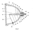
- FIG. 1 shows, by way of example, a schematic illustration of a reflector lamp 2 according to the invention with a reflector 4, in the interior of which a high-pressure discharge lamp 8 passing through a neck region of the reflector 4 projects.
- the reflector 4 is substantially ellipsoidal and consists of pressed glass, on the inner surface 10, a reflective coating is applied.
- the interior space 6 is delimited at its light exit side by a disk 12 which acts as a splinter protection and which is inserted in a radial extension of the reflector 4.
- the disc 12 is made of glass and is connected via an adhesive 14, for example. Made of silicone with the reflector 4.
- the high-pressure discharge lamp 8 has a discharge vessel 16 made of quartz glass, which has a discharge piston 18 for delimiting a discharge space 20 and two shafts 22, 24 arranged diametrically on the discharge piston 18.
- a discharge space 20 protrude two electrodes 26, 28 which are arranged diametrically opposite one another and between which a gas discharge is formed during lamp operation.
- the discharge space 20 is filled with an ionizable filling, which consists essentially of a high-purity noble gas.
- the electrodes 26, 28 are made of tungsten and fused in the known manner by means of sealing foils 30, 32 in the shafts 22, 24.
- the sealing foils 30, 32 are made of molybdenum.
- power supply lines 34, 36 are welded.
- a power line 38 which is guided through a lateral leadthrough 40 in the reflector 4, acts on the left-hand power supply 34 as shown in FIG.
- the illustrated in the view in Figure 1 right power supply 36 is connected directly to a base 42 which engages around a free end of the shaft 24 which is disposed outside of the inner space 6.
- the neck region of the reflector 4 is designed as a cylindrical projection 46, in which a bore 44 which widens radially in the direction away from the inner space 6 is designed to pass through the shank 24.
- the high-pressure discharge lamp 8 is fixed by means of a connecting compound 48, which is filled in an annular space 50 between the shaft 24 and an inner wall 52 of the bore 44 and likewise partially encloses the base 42, so that it is firmly connected to the shaft 24.
- the bonding compound 48 is a per se known ceramic cement based on silicate or a sour iron cement and when filling in the annular space 50 preferably so tough that it does not flow into the interior 6.
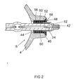
- a protective layer 60 which extends essentially from a shoulder surface 56 of the bore 44 to the end face 62 of the shaft 24, extends from the section 44 of the shaft 24 passing through the bore 44 Socket 42 is covered.
- the protective layer 60 causes the bonding compound 48 does not attack directly on the shaft 24 and thus the bonding compound 48 can not introduce sharp notches in the quartz glass of the section 58, whereby the stability of the reflector lamp 2 according to the invention over known solutions is increased.
- the protective layer 60 prevents the shaft 24 from being damaged and its probability of breakage being increased.
- the protective layer 60 is applied with a layer thickness of less than 1 mm, wherein the layer thickness is preferably 0.1 mm.
- the protective layer 60 is a suspension of the bonding compound 48, wherein for the preparation of the suspension, the bonding compound 48 is diluted with water.
- at least one additive may be added to the suspension. Possible additives are, for example, hollow glass beads in a powder, which are known for mixing lightweight fillers, adhesives and molding compounds or Aerosil® known per se.
- the composition of the suspension is selected such that the protective layer 60 does not essentially attack the quartz glass and, at the same time, there is sufficient adhesion on the section 58. It has been shown that the protective layer 50 is pressed against the shaft 24 by the hardened bonding compound 48 and thus the adhesion of the protective layer 60 on the section 58 is improved.
- An exemplary composition of the suspension comprises 30% of the Bonding compound 48, 50% water and 20% of one or more of the aggregates.
- the protective layer 60 is first applied to the section 58. Subsequently, the protective layer 60 is dried, preferably air-dried, and cured in an oven at about 250 ° C. Then, the high-pressure discharge lamp 8 is guided with its coated portion 58 through the bore 44 and the ceramic ring 54 is inserted. Subsequently, the annular space 50 is at least partially filled with the bonding compound 48, so that the high-pressure discharge lamp 8 is surrounded at least in the vicinity of a ceramic ring, not shown here of the connecting mass 48 and thus firmly connected after curing of the bonding compound 48 with the reflector 4.
- the protective layer 60 according to the invention is not limited to the suspension of the bonding compound 48 described here by way of example, but other compositions or materials for producing the protective layer 60 are also possible.
- a lamp 8 with a lamp vessel 16 which is received with a portion 58 in a receptacle 44 of a holding body 4 and fixed by means of a bonding compound 48, wherein on the portion 58, a protective layer 60 is applied. Furthermore, a method of manufacturing such a lamp is disclosed.
Landscapes
- Engineering & Computer Science (AREA)
- Manufacturing & Machinery (AREA)
- General Engineering & Computer Science (AREA)
- Vessels And Coating Films For Discharge Lamps (AREA)
- Non-Portable Lighting Devices Or Systems Thereof (AREA)
- Fastening Of Light Sources Or Lamp Holders (AREA)
Abstract
Description
- Die Erfindung betrifft eine Lampe gemäß dem Oberbegriff des Patentanspruchs 1 sowie ein Verfahren zur Herstellung einer derartigen Lampe gemäß dem Patentanspruch 6.
- Eine derartige Lampe ist zum Beispiel in der
EP 1 158 354 A1 offenbart. Diese Lampe ist eine Reflektor-Hochdruckentladungslampe mit einem Reflektor, der einen Innenraum begrenzt, und mit einem Entladungsgefäß aus Quarzglas. Das Entladungsgefäß ragt in den Innenraum hinein, wobei es mit einem Schaft, einen Halsbereich des Reflektors durchsetzt und in diesem über eine Verbindungsmasse fixiert ist. Problematisch bei dieser Art der Fixierung ist, dass durch die jeweilige chemische Zusammensetzung der Verbindungsmasse, Aushärtungsbedingungen und temperaturabhängige Spannungen beim Lampenbetrieb der von der Verbindungsmasse umgebene Schaft angegriffen wird und Kräfte auf den Schaft ausgeübt werden, die zum Schaftbruch und damit zum Ausfall der Lampe führen können. Darüber hinaus können durch die Verbindungsmasse im Quarzglas scharfe Kerben entstehen, die quasi als Sollbruchstellen wirken. Zur Vermeidung derartiger Beschädigungen wird üblicherweise ein Kompromiss zwischen notwendigen Haltekräften der Verbindungsmasse und der Bruchwahrscheinlichkeit des Schaftes angestrebt. Es hat sich jedoch gezeigt, dass selbst bei minimal erforderlichen Haltekräften zwischen der Verbindungsmasse und dem Schaft eine deutliche Bruchwahrscheinlichkeit des Schaftes besteht. - Der Erfindung liegt die Aufgabe zugrunde, eine Lampe sowie ein Verfahren zur Herstellung einer derartigen Lampe zu schaffen, die gegenüber herkömmlichen Lösungen eine verbesserte Stabilität aufweist.
- Diese Aufgabe wird hinsichtlich der Lampe durch die Merkmalskombination des Patentanspruchs 1 und hinsichtlich des Verfahrens durch die Merkmalskombination des Patentanspruchs 6 gelöst. Besonders vorteilhafte Ausführungen der Erfindung sind in den abhängigen Patentansprüchen beschrieben.
- Die erfindungsgemäße Lampe hat ein Lampengefäß, das mit einem Abschnitt in einer Aufnahme eines Haltekörpers aufgenommen und mittels einer Verbindungsmasse fixiert ist. Erfindungsgemäß ist auf dem Abschnitt eine Schutzschicht aufgetragen.
- Das erfindungsgemäße Verfahren zur Herstellung einer Lampe weist erfindungsgemäß die Schritte auf:
- Auftragen einer Schutzschicht auf einen Abschnitt eines Lampengefäßes,
- Aushärten der Schutzschicht,
- Positionieren des Abschnitts in einer Aufnahme eines Haltekörpers und
- Fixieren des Abschnitts in der Aufnahme mit einer Verbindungsmasse.
- Die erfindungsgemäße Lösung hat den Vorteil, dass durch die Schutzschicht die Verbindungsmasse nicht mehr unmittelbar an dem Lampengefäß angreift, so dass durch die Verbindungsmasse keine Beschädigung des Lampengefäßes erfolgt und somit die Bruchwahrscheinlichkeit des Lampengefäßes nicht erhöht ist.
- Gemäß einem besonders bevorzugten Ausführungsbeispiel ist die Schutzschicht eine ausgehärtete Suspension der Verbindungsmasse.
- Vorzugsweise ist der Suspension ein Zuschlagstoff zur Verbesserung der Viskosität und zur Verminderung der aggressiven Eigenschaften der Verbindungsmasse beigemischt.
- Bei einem Ausführungsbeispiel enthält die Verbindungsmasse Sauereisenzement und als Zuschlagstoff Glaskugeln oder Aerosil®.
- Die Schutzschicht weist vorzugsweise eine Schichtdicke von etwa maximal 1 mm auf. Insbesondere ist eine Schichtdicke von 0,1 mm vorstellbar.
- Die Aushärtung der Suspension kann bei einer Temperatur von etwa 250°C erfolgen.
- Nachstehend wird die Erfindung anhand eines bevorzugten Ausführungsbeispiels näher erläutert. Es zeigen:
- Figur 1
- eine schematische Darstellung einer erfindungsgemäßen Lampe und
- Figur 2
- eine Vergrößerung eines Halsbereiches der Lampe aus Figur 1.
- Figur 1 zeigt beispielhaft eine schematische Darstellung einer erfindungsgemäßen Reflektorlampe 2 mit einem Reflektor 4, in dessen Innenraum 6 eine einen Halsbereich des Reflektors 4 durchsetzende Hochdruckentladungslampe 8 hineinragt. Der Reflektor 4 ist im Wesentlichen ellipsoidförmig und besteht aus Pressglas, auf dessen Innenfläche 10 eine reflektierende Beschichtung aufgetragen ist. Der Innenraum 6 ist an seiner Lichtaustrittsseite durch eine als Splitterschutz wirkende Scheibe 12 begrenzt, die in eine radiale Erweiterung des Reflektors 4 eingesetzt ist. Die Scheibe 12 besteht aus Glas und ist über einen Klebstoff 14 bspw. aus Silikon mit dem Reflektor 4 verbunden.
- Die Hochdruckentladungslampe 8 hat ein Entladungsgefäß 16 aus Quarzglas, welches einen Entladungskolben 18 zur Begrenzung eines Entladungsraums 20 sowie zwei diametral an dem Entladungskolben 18 angeordnete Schäfte 22, 24 aufweist. In den Entladungsraum 20 ragen zwei Elektroden 26, 28 hinein, die diametral zueinander angeordnet sind und zwischen denen sich während des Lampenbetriebs eine Gasentladung ausbildet. Der Entladungsraum 20 ist mit einer ionisierbaren Füllung gefüllt, die im Wesentlichen aus einem hochreinen Edelgas besteht. Die Elektroden 26, 28 sind aus Wolfram und auf bekannte Art und Weise mittels Dichtungsfolien 30, 32 in den Schäften 22, 24 eingeschmolzen. Vorzugsweise bestehen die Dichtungsfolien 30, 32 aus Molybdän. An einem von dem Entladungsraum 20 abgewandten Endabschnitt der Dichtungsfolien 30, 32 sind Stromzuführungen 34, 36 angeschweißt. Zum Anlegen einer Versorgungsspannung an die Hochdruckentladungslampe 8 greift an der gemäß der Ansicht in Figur 1 linken Stromzuführung 34 eine Stromleitung 38 an, die durch eine seitliche Durchführung 40 im Reflektor 4 geführt ist. Die gemäß der Ansicht in der Figur 1 dargestellte rechte Stromzuführung 36 ist direkt mit einem Sockel 42 verbunden, der ein freies Ende des Schaftes 24 umgreift, das außerhalb des Innenraums 6 angeordnet ist.
- Der Halsbereich des Reflektors 4 ist als ein zylindrischer Vorsprung 46 ausgebildet, in dem eine sich in Richtung weg von dem Innenraum 6 radial erweiternde Bohrung 44 zur Durchführung des Schaftes 24 ausgebildet ist. Die Fixierung der Hochdruckentladungslampe 8 erfolgt über eine Verbindungsmasse 48, die in einen Ringraum 50 zwischen dem Schaft 24 und einer Innenwandung 52 der Bohrung 44 gefüllt ist und ebenfalls abschnittsweise den Sockel 42 umschließt, so dass dieser fest mit dem Schaft 24 verbunden ist. Die Verbindungsmasse 48 ist ein an sich bekannter keramischer Kitt auf Silikatbasis oder ein Sauereisenzement und beim Einfüllen in den Ringraum 50 bevorzugterweise so zäh, das er nicht in den Innenraum 6 abfließt. Es ist jedoch auch möglich, den Ringraum 50 in Richtung des Innenraumes 6 durch einen in die radiale Erweiterung der Bohrung 44 eingesetzten nicht dargestellten Ring zu begrenzen, so dass bei reduzierter Zähigkeit verhindert wird, dass die Verbindungsmasse 48 aus dem Ringraum 50 in den Innenraum 6 des Reflektors 4 eindringt.
- Nach der vergrößerten Darstellung des Halsbereiches in Figur 2 ist erfindungsgemäß auf einen die Bohrung 44 durchsetzenden Abschnitt 58 des Schaftes 24 eine Schutzschicht 60 aufgetragen, die sich im Wesentlichen von einer Schulterfläche 56 der Bohrung 44 bis zur Stirnfläche 62 des Schaftes 24 erstreckt, die von dem Sockel 42 abgedeckt ist. Die Schutzschicht 60 bewirkt, dass die Verbindungsmasse 48 nicht unmittelbar an dem Schaft 24 angreift und somit die Verbindungsmasse 48 keine scharfen Kerben in das Quarzglas des Abschnittes 58 einbringen kann, wodurch die Stabilität der erfindungsgemäßen Reflektorlampe 2 gegenüber bekannten Lösungen erhöht ist. Die Schutzschicht 60 verhindert, dass der Schaft 24 beschädigt wird und dessen Bruchwahrscheinlichkeit erhöht ist. Vorzugsweise ist die Schutzschicht 60 mit einer Schichtdicke von weniger als 1 mm aufgetragen, wobei die Schichtdicke bevorzugterweise 0,1 mm beträgt.
- Es ist jedoch auch vorstellbar, mehrere Schutzschichten 60 übereinander, d. h. mehrlagig, auf dem Abschnitt 58 vorzusehen. Selbstverständlich kann dabei die Schichtdicke der einzelnen Schutzschichten 58 und deren Zusammensetzung variieren.
- Bei dem dargestellten Ausführungsbeispiel ist die Schutzschicht 60 eine Suspension der Verbindungsmasse 48, wobei zur Herstellung der Suspension die Verbindungsmasse 48 mit Wasser verdünnt ist. Zur Erhöhung' der Viskosität sowie zur Verminderung der aggressiven Eigenschaften der Verbindungsmasse kann der Suspension zumindest ein Zuschlagstoff beigemischt sein. Mögliche Zuschlagstoffe sind zum Beispiel hohle Glaskugeln in einem Pulver, die zum Anmischen von Leichtspachteln, Klebstoffen und Pressmassen bekannt sind oder per se bekanntes Aerosil®. Die Zusammensetzung der Suspension ist so gewählt, dass die Schutzschicht 60 das Quarzglas im Wesentlichen nicht angreift und gleichzeitig eine ausreichende Haftung auf dem Abschnitt 58 gegeben ist. Dabei hat sich gezeigt, dass durch die ausgehärtete Verbindungsmasse 48 die Schutzschicht 50 gegen den Schaft 24 gedrückt wird und somit die Haftung der Schutzschicht 60 auf dem Abschnitt 58 verbessert ist. Eine beispielhafte Zusammensetzung der Suspension weist 30 % der Verbindungsmasse 48, 50 % Wasser und 20 % eines oder mehrere der Zuschlagstoffe auf.
- Zur Herstellung der beispielhaften erfindungsgemäßen Reflektorlampe 2 wird zunächst die Schutzschicht 60 auf den Abschnitt 58 aufgetragen. Anschließend wird die Schutzschicht 60 getrocknet, vorzugsweise luftgetrocknet, und in einem Ofen bei etwa 250°C zur Aushärtung gebracht. Dann wird die Hochdruckentladungslampe 8 mit ihrem beschichteten Abschnitt 58 durch die Bohrung 44 geführt und der Keramikring 54 eingesetzt. Anschließend wird der Ringraum 50 zumindest teilweise mit der Verbindungsmasse 48 befüllt, so dass die Hochdruckentladungslampe 8 zumindest in Nähe eines hier nicht dargestellten Keramikringes von der Verbindungsmasse 48 umgeben und somit nach einer Aushärtung der Verbindungsmasse 48 mit dem Reflektor 4 fest verbunden ist.
- Es sei erwähnt, dass die erfindungsgemäße Schutzschicht 60 nicht auf die hier beispielhaft beschriebene Suspension der Verbindungsmasse 48 beschränkt ist, sondern ebenfalls andere Zusammensetzungen bzw. Materialien zur Herstellung der Schutzschicht 60 möglich sind.
- Offenbart ist eine Lampe 8 mit einem Lampengefäß 16, das mit einem Abschnitt 58 in einer Aufnahme 44 eines Haltekörpers 4 aufgenommen und mittels einer Verbindungsmasse 48 fixiert ist, wobei auf dem Abschnitt 58 eine Schutzschicht 60 aufgetragen ist. Des Weiteren ist ein Verfahren zur Herstellung einer derartigen Lampe offenbart.
Claims (8)
- Lampe mit einem Lampengefäß (16), das mit einem Abschnitt (58) in einer Aufnahme (44) eines Haltekörpers (4) aufgenommen und mittels einer Verbindungsmasse (48) fixiert ist, dadurch gekennzeichnet, dass auf dem Abschnitt (58) zumindest eine Schutzschicht (60) aufgebracht ist.
- Lampe nach Anspruch 1, wobei die Schutzschicht (60) eine ausgehärtete Suspension der Verbindungsmasse (48) ist.
- Lampe nach Anspruch 2, wobei die Suspension einen Zuschlagstoff zur Verbesserung der Viskosität enthält.
- Lampe nach Anspruch 3, wobei die Verbindungsmasse (48) Sauereisenzement enthält und der Zuschlagstoff Glaskugeln oder Aerosil® aufweist.
- Lampe nach einem der vorhergehenden Ansprüche, wobei die Schutzschicht (60) eine Schichtdicke von etwa maximal 1 mm, vorzugsweise 0,1 mm aufweist.
- Verfahren zur Herstellung einer Lampe (2) nach einem der vorhergehenden Ansprüche, mit den Schritten:- Auftragen einer Schutzschicht (60) auf einen Abschnitt eines Lampengefäßes,- Aushärten der Schutzschicht (60),- Positionieren des Abschnitts (58) in einer Aufnahme (44) eines Haltekörpers (4) und- Fixieren des Abschnitts in der Aufnahme (44) mit einer Verbindungsmasse (48).
- Verfahren nach Anspruch 6, wobei die Schutzschicht (60) als Suspension der Verbindungsmasse (48) aufgetragen wird.
- Verfahren nach Anspruch 7, wobei die Suspension bei einer Temperatur von etwa 250°C ausgehärtet wird.
Applications Claiming Priority (1)
| Application Number | Priority Date | Filing Date | Title |
|---|---|---|---|
| DE102005034145A DE102005034145A1 (de) | 2005-07-19 | 2005-07-19 | Lampe mit Schutzschicht und Verfahren zur Herstellung einer derartigen Lampe |
Publications (3)
| Publication Number | Publication Date |
|---|---|
| EP1746621A2 true EP1746621A2 (de) | 2007-01-24 |
| EP1746621A3 EP1746621A3 (de) | 2011-11-23 |
| EP1746621B1 EP1746621B1 (de) | 2013-01-23 |
Family
ID=37308778
Family Applications (1)
| Application Number | Title | Priority Date | Filing Date |
|---|---|---|---|
| EP06014298A Ceased EP1746621B1 (de) | 2005-07-19 | 2006-07-10 | Lampe mit Schutzschicht und Verfahren zur Herstellung einer derartigen Lampe |
Country Status (7)
| Country | Link |
|---|---|
| US (1) | US20070018554A1 (de) |
| EP (1) | EP1746621B1 (de) |
| JP (1) | JP2007027127A (de) |
| KR (1) | KR20070011156A (de) |
| CN (1) | CN1900584B (de) |
| DE (1) | DE102005034145A1 (de) |
| TW (1) | TWI404112B (de) |
Citations (1)
| Publication number | Priority date | Publication date | Assignee | Title |
|---|---|---|---|---|
| EP1158354A1 (de) | 1999-12-02 | 2001-11-28 | Matsushita Electric Industrial Co., Ltd. | Entladungslampe |
Family Cites Families (11)
| Publication number | Priority date | Publication date | Assignee | Title |
|---|---|---|---|---|
| US2454270A (en) * | 1945-04-10 | 1948-11-23 | Tung Sol Lamp Works Inc | Basing electric bulb |
| US4506192A (en) * | 1983-02-22 | 1985-03-19 | Gte Laboratories Incorporated | Fluorescent lamp and a base thereof |
| US4728847A (en) * | 1985-05-17 | 1988-03-01 | U.S. Philips Corporation | Electric lamp having an envelope with an intermediate zirconium oxide coated layer |
| US5821681A (en) * | 1995-09-29 | 1998-10-13 | Wedgewood Technology, Inc. | Low pressure discharge lamp assembly |
| JPH10106487A (ja) | 1996-09-30 | 1998-04-24 | Toshiba Lighting & Technol Corp | 電球形蛍光ランプおよび照明器具 |
| JP3777034B2 (ja) * | 1997-12-11 | 2006-05-24 | 株式会社小糸製作所 | 放電ランプ装置用絶縁プラグ |
| US6369502B1 (en) * | 1999-11-29 | 2002-04-09 | General Electric Company | Low pressure mercury vapor discharge lamp with doped phosphor coating |
| JP2003317658A (ja) * | 2002-04-26 | 2003-11-07 | Ushio Inc | 放電ランプ装置 |
| US20030230959A1 (en) * | 2002-06-17 | 2003-12-18 | Hickey Robert J. | Refurbished video projection lamp |
| KR101008530B1 (ko) * | 2002-11-25 | 2011-01-14 | 코닌클리케 필립스 일렉트로닉스 엔.브이. | 방전 용기, 가스-밀폐방식의 고압 버너, 상기 버너를 포함하는 램프 및 상기 램프를 제조하는 방법 |
| US6906465B2 (en) * | 2002-12-09 | 2005-06-14 | Osram Sylvania Inc. | End-of-life protection for compact fluorescent lamps |
-
2005
- 2005-07-19 DE DE102005034145A patent/DE102005034145A1/de not_active Withdrawn
-
2006
- 2006-07-10 EP EP06014298A patent/EP1746621B1/de not_active Ceased
- 2006-07-13 US US11/485,460 patent/US20070018554A1/en not_active Abandoned
- 2006-07-18 JP JP2006195628A patent/JP2007027127A/ja active Pending
- 2006-07-18 TW TW095126209A patent/TWI404112B/zh not_active IP Right Cessation
- 2006-07-19 KR KR1020060067351A patent/KR20070011156A/ko not_active Withdrawn
- 2006-07-19 CN CN2006101212629A patent/CN1900584B/zh not_active Expired - Fee Related
Patent Citations (1)
| Publication number | Priority date | Publication date | Assignee | Title |
|---|---|---|---|---|
| EP1158354A1 (de) | 1999-12-02 | 2001-11-28 | Matsushita Electric Industrial Co., Ltd. | Entladungslampe |
Also Published As
| Publication number | Publication date |
|---|---|
| KR20070011156A (ko) | 2007-01-24 |
| TW200719384A (en) | 2007-05-16 |
| CN1900584B (zh) | 2010-05-12 |
| EP1746621A3 (de) | 2011-11-23 |
| CN1900584A (zh) | 2007-01-24 |
| US20070018554A1 (en) | 2007-01-25 |
| TWI404112B (zh) | 2013-08-01 |
| DE102005034145A1 (de) | 2007-01-25 |
| JP2007027127A (ja) | 2007-02-01 |
| EP1746621B1 (de) | 2013-01-23 |
Similar Documents
| Publication | Publication Date | Title |
|---|---|---|
| EP1233193B1 (de) | Schliessringbolzen zur Herstellung einer mechanisch festen und mit einer Dichtmasse abgedichteten Verbindung von zwei oder mehreren Bauteilen | |
| DE10150656C2 (de) | Reflektor für eine Hochdruck-Gasentladungslampe | |
| EP0264764A2 (de) | Einschmelzung für eine Hochdruckentladungslampe | |
| DE2507387A1 (de) | Piezoelektrische hochspannungsanordnung | |
| DE19961551A1 (de) | Einschmelzfolie und zugehörige Lampe mit dieser Folie | |
| EP2576313A1 (de) | Radsatzwelle für ein schienengebundenes fahrzeug mit steinschlagschutz und verfahren zu deren herstellung | |
| DE3016893A1 (de) | Lichtbogenrohr fuer hochdrucknatrium- dampfentladungslampen mit verbesserter endabdichtung und verfahren zu deren herstellung | |
| DE102009051593B4 (de) | Verfahren zur Herstellung eines Werkstoffverbundes zwischen einer Oxidkeramik und einem auf diese aufzubringenden Verblendwerkstoff, Verwendung des Werkstoffverbundes sowie Kit für den Haftvermittler | |
| EP2784463B1 (de) | Druckmesszelle mit einer Einbauanordnung | |
| DE60216405T2 (de) | Turbinenschaufel, Herstellungsverfahren einer Turbinenschaufel, sowie Beurteilungsverfahren für das Ablösen einer Wärmedämmschicht | |
| EP1746621B1 (de) | Lampe mit Schutzschicht und Verfahren zur Herstellung einer derartigen Lampe | |
| DE102009003391A1 (de) | Montagesystem | |
| DE202009000057U1 (de) | Montagesystem | |
| EP0679853A1 (de) | Beschichtung für Rohrböden und Kühlmittelrohre von Wärmetauschern | |
| DE102019200848A1 (de) | Beschichtungsanordnung für Mg-Bauteile | |
| EP1958226B1 (de) | Metallhalogenidlampe und Verfahren zu Herstellung derselben | |
| DE1594059A1 (de) | Feuchtigkeitsfeste Dichtung | |
| DE3917989C2 (de) | ||
| EP1465236A2 (de) | Entladungslampe | |
| DE102006036576A1 (de) | Stromdurchführungssystem für eine Lampe | |
| DE69014456T2 (de) | Montage einer Lampe. | |
| DE69110601T2 (de) | Ein versiegeltes Kathodenstrahlrohr. | |
| DE60309517T2 (de) | Dosiervorrichtung für ein druckfluid sowie deren herstellungsverfahren | |
| DE2001425A1 (de) | Verfahren und Massen zum Abdichten keramischer Lampenkolben | |
| DE19858111C2 (de) | Abgedichteter Steckverbinder und Verfahren zu dessen Herstellung |
Legal Events
| Date | Code | Title | Description |
|---|---|---|---|
| PUAI | Public reference made under article 153(3) epc to a published international application that has entered the european phase |
Free format text: ORIGINAL CODE: 0009012 |
|
| AK | Designated contracting states |
Kind code of ref document: A2 Designated state(s): AT BE BG CH CY CZ DE DK EE ES FI FR GB GR HU IE IS IT LI LT LU LV MC NL PL PT RO SE SI SK TR |
|
| AX | Request for extension of the european patent |
Extension state: AL BA HR MK YU |
|
| PUAL | Search report despatched |
Free format text: ORIGINAL CODE: 0009013 |
|
| AK | Designated contracting states |
Kind code of ref document: A3 Designated state(s): AT BE BG CH CY CZ DE DK EE ES FI FR GB GR HU IE IS IT LI LT LU LV MC NL PL PT RO SE SI SK TR |
|
| AX | Request for extension of the european patent |
Extension state: AL BA HR MK RS |
|
| RIC1 | Information provided on ipc code assigned before grant |
Ipc: H01K 3/16 20060101ALI20111020BHEP Ipc: H01J 9/34 20060101ALI20111020BHEP Ipc: H01J 5/58 20060101ALI20111020BHEP Ipc: H01J 61/35 20060101ALI20111020BHEP Ipc: H01J 5/48 20060101AFI20111020BHEP |
|
| 17P | Request for examination filed |
Effective date: 20111219 |
|
| AKX | Designation fees paid |
Designated state(s): DE |
|
| GRAP | Despatch of communication of intention to grant a patent |
Free format text: ORIGINAL CODE: EPIDOSNIGR1 |
|
| GRAS | Grant fee paid |
Free format text: ORIGINAL CODE: EPIDOSNIGR3 |
|
| GRAA | (expected) grant |
Free format text: ORIGINAL CODE: 0009210 |
|
| RAP1 | Party data changed (applicant data changed or rights of an application transferred) |
Owner name: OSRAM GMBH |
|
| AK | Designated contracting states |
Kind code of ref document: B1 Designated state(s): DE |
|
| REG | Reference to a national code |
Ref country code: DE Ref legal event code: R096 Ref document number: 502006012446 Country of ref document: DE Effective date: 20130321 |
|
| RAP2 | Party data changed (patent owner data changed or rights of a patent transferred) |
Owner name: OSRAM GMBH |
|
| REG | Reference to a national code |
Ref country code: DE Ref legal event code: R081 Ref document number: 502006012446 Country of ref document: DE Owner name: OSRAM GMBH, DE Free format text: FORMER OWNER: PATENT-TREUHAND-GESELLSCHAFT FUER ELEKTRISCHE GLUEHLAMPEN MBH, 81543 MUENCHEN, DE Effective date: 20130123 Ref country code: DE Ref legal event code: R081 Ref document number: 502006012446 Country of ref document: DE Owner name: OSRAM GMBH, DE Free format text: FORMER OWNER: OSRAM GMBH, 81543 MUENCHEN, DE Effective date: 20130823 |
|
| PLBE | No opposition filed within time limit |
Free format text: ORIGINAL CODE: 0009261 |
|
| STAA | Information on the status of an ep patent application or granted ep patent |
Free format text: STATUS: NO OPPOSITION FILED WITHIN TIME LIMIT |
|
| 26N | No opposition filed |
Effective date: 20131024 |
|
| REG | Reference to a national code |
Ref country code: DE Ref legal event code: R097 Ref document number: 502006012446 Country of ref document: DE Effective date: 20131024 |
|
| PGFP | Annual fee paid to national office [announced via postgrant information from national office to epo] |
Ref country code: DE Payment date: 20170724 Year of fee payment: 12 |
|
| REG | Reference to a national code |
Ref country code: DE Ref legal event code: R119 Ref document number: 502006012446 Country of ref document: DE |
|
| PG25 | Lapsed in a contracting state [announced via postgrant information from national office to epo] |
Ref country code: DE Free format text: LAPSE BECAUSE OF NON-PAYMENT OF DUE FEES Effective date: 20190201 |