EP1746030B2 - System aus einer Clipmaschine und einem Clipvorrat und Verfahren zum Betreiben einer solchen Clipmaschine - Google Patents
System aus einer Clipmaschine und einem Clipvorrat und Verfahren zum Betreiben einer solchen Clipmaschine Download PDFInfo
- Publication number
- EP1746030B2 EP1746030B2 EP06010919.6A EP06010919A EP1746030B2 EP 1746030 B2 EP1746030 B2 EP 1746030B2 EP 06010919 A EP06010919 A EP 06010919A EP 1746030 B2 EP1746030 B2 EP 1746030B2
- Authority
- EP
- European Patent Office
- Prior art keywords
- clip
- closing tool
- information
- supply
- tool
- Prior art date
- Legal status (The legal status is an assumption and is not a legal conclusion. Google has not performed a legal analysis and makes no representation as to the accuracy of the status listed.)
- Active
Links
Images

Classifications
-
- A—HUMAN NECESSITIES
- A22—BUTCHERING; MEAT TREATMENT; PROCESSING POULTRY OR FISH
- A22C—PROCESSING MEAT, POULTRY, OR FISH
- A22C11/00—Sausage making ; Apparatus for handling or conveying sausage products during manufacture
- A22C11/12—Apparatus for tying sausage skins ; Clipping sausage skins
- A22C11/125—Apparatus for tying sausage skins ; Clipping sausage skins by clipping; Removal of clips
-
- B—PERFORMING OPERATIONS; TRANSPORTING
- B65—CONVEYING; PACKING; STORING; HANDLING THIN OR FILAMENTARY MATERIAL
- B65B—MACHINES, APPARATUS OR DEVICES FOR, OR METHODS OF, PACKAGING ARTICLES OR MATERIALS; UNPACKING
- B65B51/00—Devices for, or methods of, sealing or securing package folds or closures; Devices for gathering or twisting wrappers, or necks of bags
- B65B51/04—Applying separate sealing or securing members, e.g. clips
-
- B—PERFORMING OPERATIONS; TRANSPORTING
- B65—CONVEYING; PACKING; STORING; HANDLING THIN OR FILAMENTARY MATERIAL
- B65B—MACHINES, APPARATUS OR DEVICES FOR, OR METHODS OF, PACKAGING ARTICLES OR MATERIALS; UNPACKING
- B65B57/00—Automatic control, checking, warning, or safety devices
- B65B57/02—Automatic control, checking, warning, or safety devices responsive to absence, presence, abnormal feed, or misplacement of binding or wrapping material, containers, or packages
- B65B57/04—Automatic control, checking, warning, or safety devices responsive to absence, presence, abnormal feed, or misplacement of binding or wrapping material, containers, or packages and operating to control, or to stop, the feed of such material, containers, or packages
-
- B—PERFORMING OPERATIONS; TRANSPORTING
- B65—CONVEYING; PACKING; STORING; HANDLING THIN OR FILAMENTARY MATERIAL
- B65B—MACHINES, APPARATUS OR DEVICES FOR, OR METHODS OF, PACKAGING ARTICLES OR MATERIALS; UNPACKING
- B65B59/00—Arrangements to enable machines to handle articles of different sizes, to produce packages of different sizes, to vary the contents of packages, to handle different types of packaging material, or to give access for cleaning or maintenance purposes
- B65B59/003—Arrangements to enable adjustments related to the packaging material
-
- B—PERFORMING OPERATIONS; TRANSPORTING
- B65—CONVEYING; PACKING; STORING; HANDLING THIN OR FILAMENTARY MATERIAL
- B65B—MACHINES, APPARATUS OR DEVICES FOR, OR METHODS OF, PACKAGING ARTICLES OR MATERIALS; UNPACKING
- B65B2210/00—Specific aspects of the packaging machine
- B65B2210/04—Customised on demand packaging by determining a specific characteristic, e.g. shape or height, of articles or material to be packaged and selecting, creating or adapting a packaging accordingly, e.g. making a carton starting from web material
Definitions
- the invention relates to a system consisting of a clip machine and a clip stock and a method for operating such a clip machine.
- the clip machine has at least one exchangeable first closing tool, which is movable relative to a second closing tool for closing clips supplied from the clip supply around a tubular or bag-shaped packaging casing.
- the closing tools comprise in pairs in each case a punch and a die, between which the clip is deformed during the closing until the minimum distance of the closing tools (closure distance) is reached. After sealing, the closing tools are moved back to their original or open position.
- the quality of such a closure high demands are made. On the one hand, it must not be so strong that the packaging casing is damaged when closing. On the other hand, the closure must be sufficiently dense, so that, for example, in the subsequent treatment of the closed sausage (cooking, smoking, etc.) this does not slip off the packaging casing. If the clip machine is to be used for a variety of different sausage products and packaging cases, therefore, different clips are used, which differ both in their strength and in their size (leg length and material thickness). In general, therefore, at least one of the closing tools is usually interchangeable and it comes in each case to the size of the clip used appropriately matched closing tools used to achieve a well-defined Def deformation of the clip when closing.
- the interchangeable closing tool is usually the die, which can be inserted into a (precisely fitting) die position and fixed in this. Below is therefore spoken of the same meaning of the first closing tool or the die.
- the interchangeability of the closing tool generally involves the risk that after a change of the clip is either forgotten that the compatible closing tool is used, or accidentally a wrong closing tool is selected.
- the object of the invention is to improve a clip machine and a method for operating a clip machine in such a way that the risk of incorrect manipulation is reduced and the closing of a clip around the packaging envelope is made more reliable.
- the object is achieved by a system and a method of the type mentioned above with the features of the characterizing part of claim 1 and of claim 7.
- the object is further achieved by a clip machine according to claim 6.
- the clipping machine has a first sensor device which is set up to identify the supplied clips on the basis of an identifier assigned to the clips and to output a corresponding clip information signal, a second sensor device which is set up to identify and insert the first closure tool on the basis of an associated identifier output a corresponding closing tool information signal, and a controller having a signal input and an evaluation means coupled to the first and second sensor means, which is arranged to evaluate the clip information signal and the closing tool information signal and output a compatibility signal, erroneous manipulations as described above can be largely excluded.
- the compatibility signal has to be made accessible to the operator of the machine and / or an operation of the machine must be enabled or disregarded depending on the compatibility signal.
- the clip supply has a bobbin with a clip strand wound thereon and a supply label with the identifier of the supply of supplied clips, and the first sensor device in this case has a reading unit for the supply label.
- the stock label particularly preferably has an RFID section, and the reading unit of the first sensor device has means for reading out such an RFID section.
- An RFID tag is very small and can therefore be mounted almost anywhere on the clip supply and preferably on the bobbin. Another advantage is the contactless reading of the information.
- the use of RFID labels is known, for example, from the logistics industry and is used there to track the movement of goods. Therefore, the RFID tag used according to the invention fulfills two functions, namely the identification of the clip supply on the one hand and the product marking for transport or storage on the other hand.
- the identifier of the clip supply is given on the basis of geometric information supplied from the clip supply clips themselves.
- the first sensor device has a scanning system arranged along the feed device, which is set up to detect this geometric information and output a corresponding sampling information, and a comparator coupled to the scanning system is provided, which is set up to receive the sampling information. to compare with a reference, and output the result of the comparison as a clip information signal to the evaluation device.
- the sampled geometric information can be, for example, the size, contour, material thickness or the like of a clip strand guided past the clip supply on the scanning system.
- the clips are formed as integrally connected to their leg ends clips.
- the pitch of the clip (“Wavelength”) and / or leg height of the clips (“Amplitude") will be different.
- the CCD camera captures the supplied clips optically, preferably from a direction that clearly shows significant differences between different clips, and outputs image information.
- the comparison device receives this image information and compares it with a reference image and in this way assigns to the acquired image information clip size information.
- this is preferably arranged so that the generated light beam is interrupted by the passing clip strand in a determined by the material thickness, pitch and feed rate regularity, for example, whenever a leg of a clip is passed.
- the comparison device can either determine the width of the supplied clips with the aid of a clock information as a reference, or the interruption pattern is compared directly by the comparison device with a reference pattern.
- the first closing tool preferably has a tool label with the identification of the first closing tool, and the second sensor device has a reading unit for the tool label.
- the tool label can also have an RFID section and the second sensor device can have corresponding means for reading out the RFID label.
- the advantages of an RFID tag lie in the small size due to the ease attachability and the double benefit.
- the first closing tool can be identified on the basis of its geometric condition (geometric identifier).
- the clip machine has a tool receptacle (die receptacle), which as a second sensor device comprises means for scanning the geometric identifier and for outputting a corresponding scan information.
- the scanning can also take place without contact if the second sensor device has a comparison device coupled to the means for scanning, which is set up to compare the sampling information with a reference and to output the result of the comparison as closing tool information signal to the evaluation device.
- the specific embodiment can, as in the case of the first sensor device, be realized in the form of a CCD camera, a light barrier, an acoustic signal converter or any other length or distance measuring device.
- the clipping machine has a display device coupled to the controller, which is set up to output an optical and / or acoustic signal on the basis of the compatibility signal output by the controller if the first closing tool and the clip supply are not compatible. This allows the operator of the clip machine to recognize it after loading it with a new clip supply or after changing the closing tool if it has been misused, and to eliminate the error before the clip machine is put into operation.
- control of the clip machine is set up to output a control signal on the basis of the compatibility signal, which prevents the processing of the supplied clips, when the first closure tool and the clip supply are incompatible, and which releases processing of the supplied clips when the first closure tool and the supply of supplied clips are compatible.
- This higher safety device is not only displayed to the operator when there is a faulty manipulation, but also prevent the machine from being put into operation if there is no compatibility between the closing tool and the clip.
- the controller is preferably further configured to determine and signal a desired rest position in dependence on the clip information signal and / or the closing tool information signal. Signaling includes the issuing of a signal indicative of the matter for further use as well as the immediate audible or visual indication.
- This allows in each case a simplified handling of the clip machine, since the information about the automatically detected clip size and / or size of the closure tool in use can be used to the operator - for example after a Verschdorftechnikmaschinecht - indicate that or as the rest position is wrong.
- it can be signaled by means of pictograms (arrows and the like), numerical values, colors or tones, in which direction the rest position of the closing tool is to be adjusted until the desired value is reached.
- the adjusting means further comprise an adjusting drive and a position-determining device coupled to the control, which is set up to determine the actual rest position of the closing tool, wherein the control is furthermore set up as a function of the set rest position and the actual position. Resting position to output a control signal to the adjustment.
- the controller has an interface for reading in product information and is set up to verify a match between the clip information signal and / or the closure tool information signal on the one hand and the read product information on the other hand and to output a plausibility signal based on the verification result.
- the controller can be displayed to the operator whether the product selected by him, which he inputs, for example, via a keyboard which is coupled to the controller, the appropriate clip is supplied and / or the appropriate closing tool is used. As a result, the process reliability is increased again.
- the inventive method for operating such a clip machine comprises the steps of identifying an identifier of a supplied clip, outputting a corresponding clip information signal, identifying an identifier of at least one changeable first closing tool, outputting a corresponding closing tool information signal, evaluating the clip information signal and the closing tool information signal and outputting a compatibility signal.
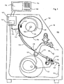
- the inventive system 100 is in Fig. 1 shown reduced to its essential elements of the invention.
- the clip machine 110 Inside its housing, the clip machine 110 according to the invention has two clip tools 112 and 114 movable relative to one another. These move toward a common center 116, which is typically defined by the tube axis of a filled packaging wrapper to be closed.
- the closure element (clip) to be closed around a hose plait previously formed by means of necking (not shown) of the clip machine 110 is fed to the first closing tool 112 as a wavy, quasi "endless" clip strand 118.
- the first closing tool 112 is therefore fastened to a lever arm 122 (lower closing lever), which is arranged around a pivot axis 120 and has a guide 124 which starts near the pivot axis 120, for the purpose of supplying the clip strand.
- the guide 124 opens into the first closing tool 112, which in the case shown is a replaceable die.
- the corresponding second closing tool 112 is a stamp.
- the closing tools fulfill two functions when moving toward one another: first the foremost clip is separated from the following clip strand 118 and then deformed around the hose plait until it is tightly closed.
- a clip feed system 130 arranged in the machine housing. This comprises a receptacle 134 arranged on an axle 132 for a clip supply on a spool 136, which carries a supply roll 138 of the clip strand processed in the clip machine 100. On the way from the spool 136 to the guide 124 located on the lower closing lever 122, the clip strand is further passed through a second guide 147 and thus guided on a path defined over substantially the entire way from the connecting element 140 to the closing tool 114.
- the embodiment of the inventive system according to Fig. 1 further comprises an identifier of the clip supply in the form of a attached to the bobbin 136 stock label 140.
- the supply label 140 on the one hand contains a section with a non-contact machine-readable. optical bar code (or 2D code) and on the other hand also a non-contact machine-readable transponder area (RFID section) in which an electromagnetically readable RF (radio frequency) information is stored.
- RFID section non-contact machine-readable transponder area
- information about the coil located on the spool may be encoded.
- a printable area can still be provided on the label for human-readable information, so that the clip size information can be entered manually if the automatically readable label sections are damaged or if the reading unit fails.
- the label can be read out accordingly by means of various sensor devices.
- the clip machine For reading in the vicinity of the clip reel, the clip machine has a first sensor device in the form of a reading unit 142, which is suitable for reading the bar code or 2D code and / or the RFID section of the label 140 (the illustration in FIG Fig. 1 is greatly simplified for purposes of illustration and does not necessarily reflect the actual location and orientation of the reader and the stock label).
- the optical reading unit comprises in a known manner a light source (laser), a lens optic and a detector for receiving the reflected light.
- the means for reading out the RFID section on the label 140 comprise, in a known manner, a transmitting and receiving antenna and electronics with which the transponder of the label can be excited.
- the supply label 140 which may be arranged at different positions depending on the angular position of the spool, it may be necessary for the spool first to be rotated into a reading position and / or to be guided past the usually stationary reading unit 142. This can be done automatically by means of a control program after inserting a new clip supply.
- the identifier read out in this way is supplied by the reading unit 142 in the form of a clip information signal via a first signal line 144 to a controller 145 and more precisely to an evaluation means 146.
- the replaceable closing tool in the form of the die 112 also has an identifier in the form of a tool label 148. in the area of the initial or open position of the lower closing lever 122 or of the first closing tool 112 according to FIG Fig. 1 a second sensor device is arranged in the form of a reading unit 150 for optically reading out the tool label (the representation in FIG Fig. 1 for illustrative purposes, and does not necessarily reflect the actual location and orientation of the reader and the stock label).
- the closing tool 112 is always in a defined position relative to the reading unit 150, ie in the case of a closing tool change, namely typically in the initial position shown, thereby simplifying the reading of the closing tool label 148. becomes.
- the tool label may also include, for example, a bar or 2D code section and / or an RFID section and / or a human-readable section. The same applies to the reading unit 150.
- the clip information signal determined by the reading unit 150 in this way from the identifier of the closing tool 112 is fed to the evaluation means 146 via a second signal line 152.
- the evaluation means 146 evaluates the clip information signal and the closure tool information signal, for example, on the basis of a tabular comparison. If the comparison reveals that the clip used and the closure tool 112 used are compatible, the evaluation means 146 within the controller 145 outputs a compatibility signal for further use.
- the clipping machine controller 145 is connected to a display device in the form of a terminal 154.
- the terminal serves by means of a screen 156 to output an optical wake signal based on the compatibility signal provided by the controller 145 when the first closure tool 112 and the clip supply are not compatible. It may further comprise a loudspeaker (not shown) which simultaneously or alternatively generates an acoustic alert signal.
- the terminal 154 further has an input keypad 158, via which - for example, menu-guided - product information can be entered to the sausage product or the like to be produced, which is supplied to the controller 145 via an interface.
- the controller 145 or a computing unit contained therein then verifies a correspondence between the clip information signal or the closing tool information signal and the product information. If there is a match, the controller 145 outputs a plausibility signal. This can in turn be entered into the display, which will do so with a confirmation message or the call of a next input menu item acknowledged. Furthermore, it can be used as a start signal for the above-described comparison between the clip information and the closure tool information or, if this comparison has already been initiated, as a start signal for the clip operation.
- the terminal 154 and / or the controller 145 may have further external interfaces for controlling a filler arranged upstream of the clipper 110 or a product removal device connected downstream of the clip machine 110.
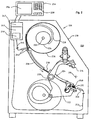
- FIG. 2 a further embodiment of the system 200 according to the invention with a clip machine 210 is shown, which except for some features essential to the invention with the clip machine Fig. 1 matches.
- the sensor unit a scanning system in the form of a light barrier 242 along the feed path of the clip strand 218 (also Fig. 2 For purposes of illustration, the reader and the label are only highly schematic and do not necessarily depict their actual location and orientation).
- the clip strand 218 passes through the light barrier 242 and triggers a periodic on-off signal, for example, when the legs of the clips pass the light barrier.
- the on-off signal is supplied via a signal line 252 to a comparator 247 associated with the sensor unit.
- At known or monitored clip feed speed. can be determined from the on-off signal by means of an additional time or clock information, the division of the clip strand and thus a geometric information of the clips supplied from the clip 218 are obtained.
- the comparator 247 further includes for this purpose an input for a clock signal and an input for a feed rate signal (both not shown). By comparing the thus determined clip division with a reference, the comparison means 247 determines the clip information and passes this as a clip information signal to the evaluation 246, the - in the same manner as described above - from the received clip information signal and Verschetzwerkmaschinemaschinectioninformationssignal the compatibility of the supplied clips 218 and inserted first closing tool 212 determined.
- the initialization of the clip machine which may include the steps described below but also, for example, a set-up method, in which the rest position of the closing tools can be determined and possibly adjusted.
- the desired product selection is queried. This can be done, for example, menu-guided via the previously described terminal 154 or via an external bus, via which the clip machine 110, 112 or its controller 145, 245 is connected, for example, to an external control / computing unit or machine. If the product selection is queried via the terminal 154, the operator can enter and confirm his selection via the keypad 258 or a touch-sensitive screen.
- step S 304 the clip stock inserted into the clip machine is identified in a step S 304. If this has been done, a plausibility check is carried out in step S 306 in which it is checked whether the identified clip stock matches the requested product selection. If this is not the case, the compatibility signal is displayed, for example, at the terminal 154 in step S 308. At the same time, a query is triggered in step S 310, which gives the operator of the machine the choice to make a new product selection or to insert a new clip stock. If it chooses the new clip set, the loop will return to step S 304 and the clip stock will be re-identified after the operator acknowledges the clip stock change or denies the new product selection. If, however, the original product selection was wrong and the operator therefore decides to make a new product selection, the product selection query S 302 again follows a corresponding acknowledgment.
- step S 312 the inserted closing tool is identified by means of the second sensor device described above.
- the result namely the lock tool information signal
- step S 314 i. For example, by a tabular comparison checks whether the identified closing tool matches the identified clip stock. If this is not the case, the result is again displayed in step S 316.
- step S 318 This can be followed by a closing tool change in step S 318 and, after the closing tool change in step S 319, another query can be made via the terminal to which the operator acknowledges the closing tool change that has taken place. Thereafter, the closing tool is re-identified in step S 312.
- step S 320 the incompatibility event is logged in step S 320.
- logged events can be read, for example, at a service and thus draw conclusions about possible mishandling or other sources of error.
- step S 322 the clip operation, ie the processing of the supplied clips, is inhibited by outputting a corresponding blocking signal by the controller until the change of the closing tool has been made in step 318 and acknowledged in step S 319 new closure tool identification S 312 has taken place and the verification in S 314 has shown that the compatibility is now given.
- the is-rest position of one or both of the closing tools 112, 114 and 212, 214 and thus the closure distance can be determined by means of a position determining device provided for this purpose.
- This is-rest position is then compared, for example, either directly to the clip information signal and / or the closure tool information signal or to a desired rest position determined from one or both signals.
- the desired rest position can, for example, in turn be carried out in the clip machine control after identification of the clip supply and / or identification of the closing tool and temporarily stored.
- Both the rest position and the desired rest position are then displayed on the terminal 154, for example, in order to signal to the operator as adjustment aid in which direction he has to adjust the rest position of the closure tool via the adjustment means, thus the desired rest position is reached. If the adjusting means of the clip machine has an adjustment drive, so that the rest position can be adjusted automatically, the result of the comparison of the rest position with the set rest position serves as a control signal for the adjustment drive.
- the replaceable closing tool is the die in the exemplary embodiments shown.
- the invention is not limited to this embodiment of the system or the clip machine.
- the second closing tool namely the punch
- the second closing tool can also be made replaceable at the same time or instead of the die, so that it can also be adapted to the size of the clip to be deformed.
- the inventive sensory detection of the stamp used can be realized accordingly, if this has an identifier and if this is associated with a sensor device which is set up in the same way to identify the identifier and output a Verschetzwerkmaschinesignal to the control of the clip machine, which this in corresponding Evaluates manner and outputs the compatibility signal in dependence (also) from the third Verschdorfwerkmaschinemaschineitatissignal.
- the clip supply does not have to be formed by a spool with a roll of the type described above. It goes without saying that the invention can find application in any type of feeding a clip supply.
- the inventive method for operating a clip machine is neither in terms of the order nor the number and type of process steps on in connection with Fig. 3 described embodiment defined.
Landscapes
- Engineering & Computer Science (AREA)
- Mechanical Engineering (AREA)
- Life Sciences & Earth Sciences (AREA)
- Wood Science & Technology (AREA)
- Zoology (AREA)
- Food Science & Technology (AREA)
- Labeling Devices (AREA)
- Automatic Assembly (AREA)
- Dovetailed Work, And Nailing Machines And Stapling Machines For Wood (AREA)
- Package Closures (AREA)
- Wrapping Of Specific Fragile Articles (AREA)
- Portable Nailing Machines And Staplers (AREA)
- Optical Recording Or Reproduction (AREA)
- Folding Of Thin Sheet-Like Materials, Special Discharging Devices, And Others (AREA)
Priority Applications (1)
| Application Number | Priority Date | Filing Date | Title |
|---|---|---|---|
| PL06010919T PL1746030T5 (pl) | 2005-07-18 | 2006-05-26 | System składający się z maszyny klipsującej i zasobnika klipsów oraz sposób eksploatacji maszyny klipsującej |
Applications Claiming Priority (1)
| Application Number | Priority Date | Filing Date | Title |
|---|---|---|---|
| DE102005033437A DE102005033437A1 (de) | 2005-07-18 | 2005-07-18 | System aus einer Clipmaschine und einem Clipvorrat und Verfahren zum Betreiben einer solchen Clipmaschine |
Publications (3)
| Publication Number | Publication Date |
|---|---|
| EP1746030A1 EP1746030A1 (de) | 2007-01-24 |
| EP1746030B1 EP1746030B1 (de) | 2008-04-30 |
| EP1746030B2 true EP1746030B2 (de) | 2016-03-23 |
Family
ID=37150833
Family Applications (1)
| Application Number | Title | Priority Date | Filing Date |
|---|---|---|---|
| EP06010919.6A Active EP1746030B2 (de) | 2005-07-18 | 2006-05-26 | System aus einer Clipmaschine und einem Clipvorrat und Verfahren zum Betreiben einer solchen Clipmaschine |
Country Status (7)
| Country | Link |
|---|---|
| US (2) | US7325380B2 (pl) |
| EP (1) | EP1746030B2 (pl) |
| CN (1) | CN1899925B (pl) |
| DE (3) | DE102005033437A1 (pl) |
| ES (1) | ES2306326T5 (pl) |
| PL (1) | PL1746030T5 (pl) |
| RU (1) | RU2429999C2 (pl) |
Families Citing this family (29)
| Publication number | Priority date | Publication date | Assignee | Title |
|---|---|---|---|---|
| PL2001748T5 (pl) * | 2006-02-03 | 2025-01-07 | Poly-Clip System Corp. | System kontrolowania klipsów |
| DE102007011423A1 (de) * | 2007-03-08 | 2008-09-11 | Poly-Clip System Gmbh & Co Kg | Schließwerkzeugbaugruppe |
| DE102007012776A1 (de) * | 2007-03-16 | 2008-09-18 | Poly-Clip System Gmbh & Co Kg | Verschlussklammer mit Rundboden |
| DE102007012778B4 (de) * | 2007-03-16 | 2010-06-24 | Poly-Clip System Gmbh & Co Kg | Einstellbarer Clipvorschub |
| DE202007006428U1 (de) | 2007-05-04 | 2007-08-16 | Poly-Clip System Gmbh & Co. Kg | Clipspule mit Transponder |
| DE102007025521A1 (de) * | 2007-05-31 | 2008-12-04 | Khs Ag | Behandlungsmaschine für Flaschen, Dosen oder dergleichen Behälter |
| DE102007050012B4 (de) * | 2007-10-17 | 2025-10-23 | Krones Aktiengesellschaft | Etikettieranlage und Vorrichtung zum Verifizieren |
| BRPI0821273A2 (pt) * | 2007-12-19 | 2015-06-16 | Tipper Tie Inc | Sistema de acondicionamento, módulo de vedação adesiva, produto de programa de computador, cavalete de carretel de grampo, mesa rotativa, mesa de suporte rotativa, e, método para acondicionar extensões de produtos |
| DE102008020046B4 (de) * | 2008-04-22 | 2012-09-06 | J+P Maschinenbau Gmbh | Einrichtung zum Führen eines Clipbandes |
| DE202008010807U1 (de) | 2008-08-05 | 2009-12-31 | Tipper Tie Technopack Gmbh | Verschlussklammer |
| ES1069622Y (es) * | 2009-02-03 | 2009-07-28 | Girnet Int Sl | Maquina para la fabricacion de bolsas |
| DE102009044163A1 (de) * | 2009-10-01 | 2011-04-07 | Krones Ag | Verfahren zum Auswechseln von Werkzeugen bei einem Verpackungs- und Lagersystem, Computerprogramm hierzu und Verpackungs- und Lagersystem |
| ES2576827T3 (es) * | 2010-02-10 | 2016-07-11 | Poly-Clip System Gmbh & Co. Kg | Máquina de grapar de operación manual |
| ES2428849T3 (es) * | 2010-12-14 | 2013-11-11 | Poly-Clip System Gmbh & Co. Kg | Suministro de clips |
| DE102011056443A1 (de) * | 2011-12-14 | 2013-06-20 | Krones Ag | Vorrichtung zum Umformen von Kunststoffvorformlingen zu Kunststoffbehältnissen mit Identifikation von Austauschteilen |
| PL2684460T3 (pl) * | 2012-07-13 | 2015-07-31 | Poly Clip System Gmbh & Co Kg | Urządzenie klipsujące |
| DE102012221458B3 (de) * | 2012-11-23 | 2013-12-12 | Sick Ag | System zur automatischen Formatverstellung einer Anlage mit Automatik-unterstütztem Formatwechsel |
| US9557719B2 (en) * | 2013-02-26 | 2017-01-31 | Honeywell International Inc. | Access control system using smart phone |
| DE102014110153A1 (de) * | 2014-07-18 | 2016-01-21 | Inotec Gmbh Maschinenentwicklung Und Vertrieb | Verfahren zum Abbinden von Würsten an einem Wurststrang |
| DE202014010142U1 (de) | 2014-12-22 | 2016-03-27 | Poly-Clip System Gmbh & Co. Kg | Clipspule |
| EA036019B1 (ru) * | 2016-10-03 | 2020-09-15 | Общество с ограниченной ответственностью "Машиностроительное предприятие "КОМПО" | Регулятор величины хода верхнего зажимного инструмента клипсатора |
| DE102017130320A1 (de) | 2017-12-18 | 2019-06-19 | Inotec Gmbh Maschinenentwicklung Und Vertrieb | Vorrichtung zum Abtrennen von Wurst |
| ES2926862T3 (es) | 2017-06-23 | 2022-10-31 | Inotec Gmbh Maschinenentwicklung Und Vertrieb | Dispositivo y procedimiento para la separación de salchichas |
| DE102017115090B4 (de) | 2017-06-23 | 2020-12-31 | Inotec Gmbh Maschinenentwicklung Und Vertrieb | Vorrichtung zum Abtrennen von Wurst |
| US11110666B2 (en) | 2018-02-12 | 2021-09-07 | Tipper Tie, Inc. | Systems with external heat-seal assembly height adjustment control and related seal assemblies |
| ES2935162T3 (es) * | 2018-05-09 | 2023-03-02 | Poly Clip System Gmbh & Co Kg | Procedimiento de control de una máquina de recorte, así como una máquina de recorte para esta |
| PL3685671T3 (pl) | 2019-01-25 | 2024-11-04 | Poly-Clip System Gmbh & Co. Kg | Wykrywanie klipsa |
| HUE056590T2 (hu) | 2019-04-29 | 2022-02-28 | Poly Clip System Gmbh & Co Kg | Rendszer élelmiszergyártó gép üzemi és gyártási paramétereinek vezeték nélküli monitorozására |
| CN110771645B (zh) * | 2019-11-29 | 2021-10-29 | 中原工学院 | 一种手动压饼机 |
Citations (1)
| Publication number | Priority date | Publication date | Assignee | Title |
|---|---|---|---|---|
| EP0549806A1 (en) † | 1991-07-12 | 1993-07-07 | ISHIDA CO., Ltd. | Bag making-wrapping machine |
Family Cites Families (28)
| Publication number | Priority date | Publication date | Assignee | Title |
|---|---|---|---|---|
| US2902783A (en) * | 1955-01-18 | 1959-09-08 | Coats & Clark | Labeled plastic spool |
| DE2352666C3 (de) * | 1973-10-19 | 1978-12-14 | Windmoeller & Hoelscher, 4540 Lengerich | Vorrichtung zum Verpacken von flachen Gegenständen, wie Beutel, Müllsäcke o.dgl. in Verpackungsbeutel |
| US5600394A (en) * | 1984-05-12 | 1997-02-04 | Eastman Kodak Company | Smart film cartridge magazine |
| US4702373A (en) * | 1986-02-24 | 1987-10-27 | Meade Dan G | Hub cover interacting with reel of magnetic tape for forming document storage compartment |
| DE3912488A1 (de) * | 1989-04-15 | 1990-10-18 | Schlafhorst & Co W | Verfahren und vorrichtung zur uebermittlung von produktinformationen und -eigenschaften einer textilspule mittels eines informationstraegers |
| US5269054A (en) * | 1992-05-15 | 1993-12-14 | Delaware Capital Formation, Inc. | Clip attachment apparatus |
| US5553810A (en) * | 1994-02-23 | 1996-09-10 | The Lincoln Electric Company | Covers for welding wire reels |
| US5735483A (en) * | 1996-06-27 | 1998-04-07 | Delaware Capital Formation, Inc. | Cardboard reel clip holder |
| DE19644074C2 (de) * | 1996-10-31 | 2001-02-22 | Poly Clip System Gmbh & Co Kg | Verfahren und Verschließvorrichtung zum Herstellen wurstartiger Produkte |
| DE19653814A1 (de) * | 1996-12-21 | 1998-06-25 | Koenig & Bauer Albert Ag | Vorratsbahnrolle |
| DE19738298C1 (de) * | 1997-09-02 | 1999-04-08 | Poly Clip System Gmbh & Co Kg | Verfahren zum Einrichten einer Verschließmaschine und Vorrichtung zum Verschließen von Verschlußklammern |
| DE19745163A1 (de) * | 1997-09-18 | 1999-03-25 | 4 P Nicolaus Kempten Gmbh | Verfahren zum Programmieren einer Maschine |
| DE19753000C2 (de) * | 1997-11-30 | 2000-08-03 | Poly Clip System Gmbh & Co Kg | Vorrichtung zum Verschließen von schlauch- oder beutelförmigen Verpackungshüllen |
| CA2277194A1 (en) * | 1998-08-12 | 2000-02-12 | Robert W. Spurr | A printer media supply spool adapted to allow the printer to sense type of media, and method of assembling same |
| US6267291B1 (en) * | 1999-06-21 | 2001-07-31 | Lincoln Global, Inc. | Coded and electronically tagged welding wire |
| DE19941485A1 (de) * | 1999-09-01 | 2000-10-26 | Bosch Gmbh Robert | Verpackungsmaschine, insbesondere zum Herstellen von Produkten enthaltenden Packungen |
| DE60133378T2 (de) * | 2000-04-20 | 2009-01-08 | Cogiscan Inc., Bromont | Automatisches herstellungssteuerungssystem |
| RU2162638C1 (ru) * | 2000-06-20 | 2001-02-10 | Закрытое акционерное общество "Клипмаш" | Клипсатор |
| EP1266830A1 (en) * | 2001-06-14 | 2002-12-18 | Tetra Laval Holdings & Finance SA | Method and system for identifying packaging material on a packaging machine |
| DE10131807C1 (de) * | 2001-06-30 | 2002-11-07 | Poly Clip System Gmbh & Co Kg | Portionierungsvorrichtung |
| US7383864B2 (en) * | 2002-04-03 | 2008-06-10 | 3M Innovative Properties Company | Radio-frequency identification tag and tape applicator, radio-frequency identification tag applicator, and methods of applying radio-frequency identification tags |
| US6739490B1 (en) * | 2002-06-24 | 2004-05-25 | Illinois Tool Works Inc. | Fastener supply and positioning mechanism for a tool |
| US6824320B1 (en) * | 2003-11-05 | 2004-11-30 | Eastman Kodak Company | Film core article and method for making same |
| US20050116034A1 (en) * | 2003-11-28 | 2005-06-02 | Masato Satake | Printing system |
| US7176799B1 (en) * | 2003-12-04 | 2007-02-13 | George Schmitt & Company | Assembling pressure sensitive labels with RFID tags |
| US7102518B2 (en) * | 2004-04-05 | 2006-09-05 | Sonoco Development, Inc. | Removable identification device for multilayer tubular structures |
| US7322163B2 (en) * | 2004-06-15 | 2008-01-29 | Tipper Tie, Inc. | Clipping packaging apparatus and methods |
| DE202007006428U1 (de) * | 2007-05-04 | 2007-08-16 | Poly-Clip System Gmbh & Co. Kg | Clipspule mit Transponder |
-
2005
- 2005-07-18 DE DE102005033437A patent/DE102005033437A1/de not_active Withdrawn
- 2005-07-18 DE DE202005021188U patent/DE202005021188U1/de not_active Expired - Lifetime
-
2006
- 2006-05-23 US US11/419,877 patent/US7325380B2/en active Active
- 2006-05-26 EP EP06010919.6A patent/EP1746030B2/de active Active
- 2006-05-26 ES ES06010919.6T patent/ES2306326T5/es active Active
- 2006-05-26 PL PL06010919T patent/PL1746030T5/pl unknown
- 2006-05-26 DE DE502006000706T patent/DE502006000706D1/de active Active
- 2006-07-17 RU RU2006125637/11A patent/RU2429999C2/ru active
- 2006-07-18 CN CN2006101285719A patent/CN1899925B/zh active Active
-
2008
- 2008-02-05 US US12/025,814 patent/US20080121677A1/en not_active Abandoned
Patent Citations (1)
| Publication number | Priority date | Publication date | Assignee | Title |
|---|---|---|---|---|
| EP0549806A1 (en) † | 1991-07-12 | 1993-07-07 | ISHIDA CO., Ltd. | Bag making-wrapping machine |
Also Published As
| Publication number | Publication date |
|---|---|
| DE502006000706D1 (de) | 2008-06-12 |
| US20080121677A1 (en) | 2008-05-29 |
| PL1746030T5 (pl) | 2017-03-31 |
| BRPI0602809A8 (pt) | 2022-03-15 |
| RU2429999C2 (ru) | 2011-09-27 |
| EP1746030A1 (de) | 2007-01-24 |
| CN1899925B (zh) | 2011-08-24 |
| DE202005021188U1 (de) | 2007-04-19 |
| US20070011990A1 (en) | 2007-01-18 |
| ES2306326T5 (es) | 2016-04-25 |
| EP1746030B1 (de) | 2008-04-30 |
| RU2006125637A (ru) | 2008-01-27 |
| BRPI0602809A (pt) | 2007-03-06 |
| CN1899925A (zh) | 2007-01-24 |
| ES2306326T3 (es) | 2008-11-01 |
| PL1746030T3 (pl) | 2008-07-31 |
| US7325380B2 (en) | 2008-02-05 |
| DE102005033437A1 (de) | 2007-02-01 |
Similar Documents
| Publication | Publication Date | Title |
|---|---|---|
| EP1746030B2 (de) | System aus einer Clipmaschine und einem Clipvorrat und Verfahren zum Betreiben einer solchen Clipmaschine | |
| EP3501995B1 (de) | Verfahren zur steuerung der parameter eines umreifungssystems | |
| EP2332846B1 (de) | Vorrichtung und Verfahren zur Behandlung von Behältnissen mit Garniturerkennung | |
| EP3439848B1 (de) | Verfahren zur bewertung mindestens eines industriellen prozesses | |
| EP0896290A2 (de) | Verfahren und Vorrichtung zum Lesen eines aus einer vorgegebenen Anzahl von Codeelementen bestehenden Strichcodes | |
| DE102014008607A1 (de) | Verfahren und Vorrichtung zum Bearbeiten eines Transportbehälters mit Wertgegenständen | |
| EP3449727A1 (de) | Vorrichtung zum füllen schlauchförmiger hüllen und betreffendes verfahren | |
| EP3087877A1 (de) | Kassensystemanordnung mit warentrennstaberkennung | |
| EP1977649B1 (de) | Unsichtbare Druckmarkierung | |
| EP2241419B1 (de) | Vorrichtung zum Aufschneiden eines Lebensmittelprodukts | |
| DE3932665A1 (de) | Ueberwachungsvorrichtung | |
| EP1428437B1 (de) | Verschliessvorrichtung für wurstförmige Verpackungen und Darmbremsanordnung für eine solche | |
| EP4135924B1 (de) | Verfahren und vorrichtung zur qualitätsbeurteilung eines bearbeitungsprozesses | |
| EP1652806B1 (de) | Vorrichtung zur Erkennung von aufeinanderfolgenden Einheiten einer endlosen Bahn | |
| EP3678868B1 (de) | Direktdruckvorrichtung zum aufbringen eines umlaufenden druckbildes | |
| DE102017202095B4 (de) | Verfahren und Vorrichtung zum Betreiben einer Warenbelegungseinheit | |
| EP3065112B1 (de) | Pfandrücknahmesystem mit schallerfassungseinheit zum erkennen der zerstörung des einweggutes | |
| DE102020000412A1 (de) | Dosiervorrichtung sowie Verfahren zur dosierten Abgabe eines Mediums | |
| EP1591272A1 (de) | Prüfung der Qualität einer Heftung von Druckprodukten | |
| EP2851875B1 (de) | Rückgabeautomat für Leergut | |
| EP4300351A1 (de) | Lesevorrichtung zum berührungslosen auslesen von informationen auf objekten und verfahren zur absicherung einer solchen lesevorrichtung | |
| EP1757522A1 (de) | Verfahren und Clipvorrichtung zum Verschliessen wurstförmiger Verpackungen | |
| EP4668157A1 (de) | Vorrichtung und verfahren zum erkennen von bestimmten produktionsmitteln an einer produktionsmaschine | |
| EP4559828A1 (de) | Verfahren zum aufbringen eines etiketts auf behälter | |
| EP1312264A1 (de) | Längeneinheit mit Clipmodul |
Legal Events
| Date | Code | Title | Description |
|---|---|---|---|
| PUAI | Public reference made under article 153(3) epc to a published international application that has entered the european phase |
Free format text: ORIGINAL CODE: 0009012 |
|
| AK | Designated contracting states |
Kind code of ref document: A1 Designated state(s): AT BE BG CH CY CZ DE DK EE ES FI FR GB GR HU IE IS IT LI LT LU LV MC NL PL PT RO SE SI SK TR |
|
| AX | Request for extension of the european patent |
Extension state: AL BA HR MK YU |
|
| 17P | Request for examination filed |
Effective date: 20070724 |
|
| AKX | Designation fees paid |
Designated state(s): CH DE ES HU IT LI PL |
|
| GRAP | Despatch of communication of intention to grant a patent |
Free format text: ORIGINAL CODE: EPIDOSNIGR1 |
|
| GRAS | Grant fee paid |
Free format text: ORIGINAL CODE: EPIDOSNIGR3 |
|
| GRAA | (expected) grant |
Free format text: ORIGINAL CODE: 0009210 |
|
| AK | Designated contracting states |
Kind code of ref document: B1 Designated state(s): CH DE ES HU IT LI PL |
|
| REG | Reference to a national code |
Ref country code: CH Ref legal event code: EP |
|
| REF | Corresponds to: |
Ref document number: 502006000706 Country of ref document: DE Date of ref document: 20080612 Kind code of ref document: P |
|
| REG | Reference to a national code |
Ref country code: PL Ref legal event code: T3 Ref country code: CH Ref legal event code: NV Representative=s name: ZIMMERLI, WAGNER & PARTNER AG |
|
| REG | Reference to a national code |
Ref country code: ES Ref legal event code: FG2A Ref document number: 2306326 Country of ref document: ES Kind code of ref document: T3 |
|
| REG | Reference to a national code |
Ref country code: HU Ref legal event code: AG4A Ref document number: E004072 Country of ref document: HU |
|
| PLBI | Opposition filed |
Free format text: ORIGINAL CODE: 0009260 |
|
| PLAX | Notice of opposition and request to file observation + time limit sent |
Free format text: ORIGINAL CODE: EPIDOSNOBS2 |
|
| 26 | Opposition filed |
Opponent name: TIPPER TIE TECHNOPACK GMBH Effective date: 20090129 |
|
| PLAF | Information modified related to communication of a notice of opposition and request to file observations + time limit |
Free format text: ORIGINAL CODE: EPIDOSCOBS2 |
|
| PLBB | Reply of patent proprietor to notice(s) of opposition received |
Free format text: ORIGINAL CODE: EPIDOSNOBS3 |
|
| REG | Reference to a national code |
Ref country code: CH Ref legal event code: PFA Owner name: POLY-CLIP SYSTEM GMBH & CO. KG Free format text: POLY-CLIP SYSTEM GMBH & CO. KG#WESTERBACHSTRASSE 45#60489 FRANKFURT AM MAIN (DE) -TRANSFER TO- POLY-CLIP SYSTEM GMBH & CO. KG#WESTERBACHSTRASSE 45#60489 FRANKFURT AM MAIN (DE) |
|
| RIN2 | Information on inventor provided after grant (corrected) |
Inventor name: MEYRAHN, JOACHIM, DR. Inventor name: EBERT, DETLEF |
|
| APBM | Appeal reference recorded |
Free format text: ORIGINAL CODE: EPIDOSNREFNO |
|
| APBP | Date of receipt of notice of appeal recorded |
Free format text: ORIGINAL CODE: EPIDOSNNOA2O |
|
| APAH | Appeal reference modified |
Free format text: ORIGINAL CODE: EPIDOSCREFNO |
|
| APBM | Appeal reference recorded |
Free format text: ORIGINAL CODE: EPIDOSNREFNO |
|
| APBP | Date of receipt of notice of appeal recorded |
Free format text: ORIGINAL CODE: EPIDOSNNOA2O |
|
| RAP2 | Party data changed (patent owner data changed or rights of a patent transferred) |
Owner name: POLY-CLIP SYSTEM GMBH & CO. KG |
|
| APBQ | Date of receipt of statement of grounds of appeal recorded |
Free format text: ORIGINAL CODE: EPIDOSNNOA3O |
|
| REG | Reference to a national code |
Ref country code: CH Ref legal event code: PFA Owner name: POLY-CLIP SYSTEM GMBH & CO. KG Free format text: POLY-CLIP SYSTEM GMBH & CO. KG#WESTERBACHSTRASSE 45#60489 FRANKFURT AM MAIN (DE) -TRANSFER TO- POLY-CLIP SYSTEM GMBH & CO. KG#NIEDECKERSTRASSE 1#65795 HATTERSHEIM (DE) |
|
| RAP2 | Party data changed (patent owner data changed or rights of a patent transferred) |
Owner name: POLY-CLIP SYSTEM GMBH & CO. KG |
|
| REG | Reference to a national code |
Ref country code: DE Ref legal event code: R082 Ref document number: 502006000706 Country of ref document: DE Representative=s name: EISENFUEHR, SPEISER & PARTNER, DE |
|
| REG | Reference to a national code |
Ref country code: HU Ref legal event code: HC9C Owner name: POLY-CLIP SYSTEM GMBH & CO. KG, DE Free format text: FORMER OWNER(S): POLY-CLIP SYSTEM GMBH & CO. KG, DE |
|
| REG | Reference to a national code |
Ref country code: DE Ref legal event code: R081 Ref document number: 502006000706 Country of ref document: DE Owner name: POLY-CLIP SYSTEM GMBH & CO. KG, DE Free format text: FORMER OWNER: POLY-CLIP SYSTEM GMBH & CO KG, 60489 FRANKFURT, DE Effective date: 20130827 Ref country code: DE Ref legal event code: R082 Ref document number: 502006000706 Country of ref document: DE Representative=s name: EISENFUEHR SPEISER PATENTANWAELTE RECHTSANWAEL, DE Effective date: 20130827 |
|
| REG | Reference to a national code |
Ref country code: CH Ref legal event code: NV Representative=s name: WAGNER PATENT AG, CH |
|
| APBU | Appeal procedure closed |
Free format text: ORIGINAL CODE: EPIDOSNNOA9O |
|
| PUAH | Patent maintained in amended form |
Free format text: ORIGINAL CODE: 0009272 |
|
| STAA | Information on the status of an ep patent application or granted ep patent |
Free format text: STATUS: PATENT MAINTAINED AS AMENDED |
|
| 27A | Patent maintained in amended form |
Effective date: 20160323 |
|
| AK | Designated contracting states |
Kind code of ref document: B2 Designated state(s): CH DE ES HU IT LI PL |
|
| REG | Reference to a national code |
Ref country code: DE Ref legal event code: R102 Ref document number: 502006000706 Country of ref document: DE |
|
| REG | Reference to a national code |
Ref country code: CH Ref legal event code: AELC |
|
| REG | Reference to a national code |
Ref country code: ES Ref legal event code: DC2A Ref document number: 2306326 Country of ref document: ES Kind code of ref document: T5 Effective date: 20160425 |
|
| P01 | Opt-out of the competence of the unified patent court (upc) registered |
Effective date: 20230519 |
|
| PGFP | Annual fee paid to national office [announced via postgrant information from national office to epo] |
Ref country code: PL Payment date: 20250519 Year of fee payment: 20 Ref country code: DE Payment date: 20250606 Year of fee payment: 20 |
|
| PGFP | Annual fee paid to national office [announced via postgrant information from national office to epo] |
Ref country code: ES Payment date: 20250616 Year of fee payment: 20 |
|
| PGFP | Annual fee paid to national office [announced via postgrant information from national office to epo] |
Ref country code: IT Payment date: 20250522 Year of fee payment: 20 |
|
| PGFP | Annual fee paid to national office [announced via postgrant information from national office to epo] |
Ref country code: HU Payment date: 20250619 Year of fee payment: 20 |
|
| PGFP | Annual fee paid to national office [announced via postgrant information from national office to epo] |
Ref country code: CH Payment date: 20250601 Year of fee payment: 20 |