EP1743569B1 - Endoskopvorrichtung zum Wiederaufnehmen/Transportieren einer medizinischen Kapsel - Google Patents
Endoskopvorrichtung zum Wiederaufnehmen/Transportieren einer medizinischen Kapsel Download PDFInfo
- Publication number
- EP1743569B1 EP1743569B1 EP06014733.7A EP06014733A EP1743569B1 EP 1743569 B1 EP1743569 B1 EP 1743569B1 EP 06014733 A EP06014733 A EP 06014733A EP 1743569 B1 EP1743569 B1 EP 1743569B1
- Authority
- EP
- European Patent Office
- Prior art keywords
- hood member
- distal end
- medical capsule
- balloon
- endoscopic apparatus
- Prior art date
- Legal status (The legal status is an assumption and is not a legal conclusion. Google has not performed a legal analysis and makes no representation as to the accuracy of the status listed.)
- Active
Links
Images


Classifications
-
- A—HUMAN NECESSITIES
- A61—MEDICAL OR VETERINARY SCIENCE; HYGIENE
- A61B—DIAGNOSIS; SURGERY; IDENTIFICATION
- A61B1/00—Instruments for performing medical examinations of the interior of cavities or tubes of the body by visual or photographical inspection, e.g. endoscopes; Illuminating arrangements therefor
- A61B1/273—Instruments for performing medical examinations of the interior of cavities or tubes of the body by visual or photographical inspection, e.g. endoscopes; Illuminating arrangements therefor for the upper alimentary canal, e.g. oesophagoscopes, gastroscopes
-
- A—HUMAN NECESSITIES
- A61—MEDICAL OR VETERINARY SCIENCE; HYGIENE
- A61B—DIAGNOSIS; SURGERY; IDENTIFICATION
- A61B1/00—Instruments for performing medical examinations of the interior of cavities or tubes of the body by visual or photographical inspection, e.g. endoscopes; Illuminating arrangements therefor
- A61B1/00147—Holding or positioning arrangements
- A61B1/00148—Holding or positioning arrangements using anchoring means
-
- A—HUMAN NECESSITIES
- A61—MEDICAL OR VETERINARY SCIENCE; HYGIENE
- A61B—DIAGNOSIS; SURGERY; IDENTIFICATION
- A61B1/00—Instruments for performing medical examinations of the interior of cavities or tubes of the body by visual or photographical inspection, e.g. endoscopes; Illuminating arrangements therefor
- A61B1/04—Instruments for performing medical examinations of the interior of cavities or tubes of the body by visual or photographical inspection, e.g. endoscopes; Illuminating arrangements therefor combined with photographic or television appliances
- A61B1/041—Capsule endoscopes for imaging
-
- A—HUMAN NECESSITIES
- A61—MEDICAL OR VETERINARY SCIENCE; HYGIENE
- A61B—DIAGNOSIS; SURGERY; IDENTIFICATION
- A61B1/00—Instruments for performing medical examinations of the interior of cavities or tubes of the body by visual or photographical inspection, e.g. endoscopes; Illuminating arrangements therefor
- A61B1/31—Instruments for performing medical examinations of the interior of cavities or tubes of the body by visual or photographical inspection, e.g. endoscopes; Illuminating arrangements therefor for the rectum, e.g. proctoscopes, sigmoidoscopes, colonoscopes
Definitions
- the present invention relates to an endoscopic apparatus according to the preamble of claim 1. It is used for holding a medical capsule in lower gastrointestinal tract such as small intestine or colon to collect or transport it.
- capsule endoscopes for medical use, various types of capsule endoscopes containing miniature cameras have been developed. Because such capsule endoscopes are wireless, patient discomfort can be decreased compared to the case with an endoscope in which an inserting section of the endoscope is also inserted in his/her body cavity.
- a medical capsule such as a capsule endoscope is generally expected to be naturally extruded out of a body cavity, but there is a need to collect the medical capsule at a predetermined position in a body cavity. Also, a medical capsule often gets stuck at a narrow portion of a body cavity, which requires a procedure to find the medical capsule to hold it in order to collect it or to bring it beyond the narrow portion. Moreover, in recent years, there has been a need to transport a medical capsule to a predetermined position in body cavity so that an observation can be started from the position. In these various applications, it is necessary to hold a medical capsule in a body cavity.
- an endoscopic apparatus having a function to hold a medical capsule in a body cavity.
- an endoscopic apparatus disclosed in Japanese Patent Application Laid-Open No. 2004-194976 has an inserting section with a distal end formed with a suction opening to suck and hold a medical capsule therein.
- the endoscopic apparatus disclosed in Japanese Patent Application Laid-Open No. 2004-194976 attracts and holds a medical capsule having an outer diameter of usually on the order of 10 mm in a suction opening thereof having a small inner diameter of 2 to 4 mm, which means the endoscopic apparatus does not have a enough power to hold a capsule, and the medical capsule can be fallen.
- the endoscopic apparatus disclosed in Japanese Patent Application Laid-Open No. 2004-194976 has another problem that even if a held medical capsule is fallen, the falling is not recognizable because the endoscopic apparatus holds the capsule at a position which is unlikely to be within a range for observation and it is difficult to check the capsule visually, and the fallen medical capsule has to be located again.
- the present invention is made in view of the above problems, and one object of the present invention is to provide a method for collecting/transporting a medical capsule which reliably holds a medical capsule in body cavity to collect or transport, and an endoscopic apparatus for the method.
- US 2002/0035311 A1 discloses an endoscope apparatus, in which the hood member is in the form of a cylindrical piece having an inner flange. The endoscope apparatus is used for aspirating mucosa and the flange is used for regulating aspirated mucosa.
- the material of the hood member is formed of the same materials throughout its length.
- the present invention provides an endoscopic apparatus, comprising the features of claim 1.
- the hood member can hold a medical capsule at the holding section thereof.
- a medical capsule is reliably held, which prevents the medical capsule from falling.
- the held medical capsule can be observed by an observation section of an endoscope.
- the configuration to hold a medical capsule with at least a part of the medical capsule being pulled into the inside of the hood member increases a holding power, which can reliably prevent the medical capsule from falling.
- At least a part of the hood member is transparent or semitransparent. Because at least a part of the hood member is transparent or semitransparent, view is not restricted while the endoscopic apparatus is inserted to find a medical capsule, and even when the hood member holds a medical capsule, the outside of the hood member can be observed by the observation section.
- the endoscopic apparatus further comprises: a first expandable and contractible balloon which is mounted to an outer circumferential surface of the distal end of the inserting section, an insertion assisting tool into which the inserting section is inserted to be guided in a body cavity; and a second expandable and contractible balloon which is mounted to an outer circumferential surface of the insertion assisting tool.
- This type of endoscopic apparatus makes it possible to hold a medical capsule at an inside of lower gastrointestinal tract such as small intestine.
- the present invention provides an endoscopic apparatus, wherein the holding section is configured to include a distal end of the hood member having an inner circumferential surface which has a curved portion corresponding to a curved shape of the medical capsule.
- the vacuum hood member has an increased airtightness so that the hood member and the medical capsule are attracted more closely to each other, which in turn increased the power to hold the medical capsule. This allows a medical capsule to be reliably held at the holding section of the hood member.
- the present invention provides an endoscopic apparatus, wherein the holding section is configured to include a distal end of the hood member which is formed thinner than any other parts of the hood member.
- the hood member and a medical capsule are attracted closely to each other even when the hood member approaches the medical capsule at an angle. In this way, the increased airtightness of the vacuum hood member improves the power to hold the medical capsule, which allows a medical capsule to be reliably held at the holding section of the hood member.
- the present invention provides an endoscopic apparatus, wherein the holding section is configured to include a distal end of the hood member having an inner circumferential surface in which a groove is formed in the circumferential direction.
- the groove in the inner circumferential surface of the distal end of the hood member makes the distal of the hood member flexible, the closeness between the hood member and a medical capsule is not reduced even when the hood member approaches the medical capsule at an angle. In this way, the increased airtightness of the vacuum hood member improves the power to hold the medical capsule, which allows a medical capsule to be reliably held at the holding section of the hood member.
- the present invention provides an endoscopic apparatus, wherein the holding section is configured to include a distal end of the hood member having an outer circumferential surface in which a groove is formed.
- the groove in the outer circumferential surface of the distal end of the hood member makes the distal of the hood member flexible, the closeness between the hood member and a medical capsule is not reduced even when the hood member approaches the medical capsule at an angle. In this way, the increased airtightness of the vacuum hood member improves the power to hold the medical capsule, which allows a medical capsule to be reliably held at the holding section of the hood member.
- the present invention provides an endoscopic apparatus, wherein there are a plurality of the grooves in a direction along a central axis of the hood member with ribs being formed between the grooves.
- the grooves in a direction along the central axis of the hood member make the distal end flexible, and the rib makes the distal end appropriately rigid.
- the inside of a hood member is sucked through a suction opening to make the inside of the hood member vacuum so that a medical capsule can be attracted to and held by the hood member, thereby the medical capsule can be reliably held by the hood member without falling.
- the held medical capsule can be observed by an observation section of an endoscope.
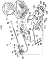
- Fig. 1 is a system configuration diagram to show an embodiment of an endoscopic apparatus according to the present invention.
- an endoscopic apparatus generally comprises an endoscope 10, an insertion assisting tool 70, and a balloon controlling device 100.
- the endoscope 10 comprises a hand-held control section 14 and an inserting section 12 connected to the hand-held control section 14 to be inserted into a body cavity.
- the hand-held control section 14 is connected to a universal cable 16 having an end which is provided with a LG connector 18.
- the LG connector 18 is removably coupled to a light source device 20 which sends an illumination light to an illumination optical system 54 which will be explained below (see Fig. 2 ).
- the LG connector 18 is connected to an electric connector 24 via a cable 22, the electric connector 24 being removably coupled to a processor 26.
- an air and water supply button 28, a suction button 30, a shutter button 32, and a function switch button 34 are arranged in a line, and a pair of angle adjustment knobs 36 are also provided therewith.
- the hand-held control section 14 has a rear end in which an air inlet for balloon 38 is formed with a pipe which is bent into an L shape. A supply or suction of fluids such as air through the air inlet for balloon 38 makes a first balloon 60 expanded or contracted, which will be explained below.
- the inserting section 12 consists of a soft portion 40, a curved portion 42, and a distal end portion 44, starting from the hand-held control section 14, and the curved portion 42 is remotely controlled by turning the angle adjustment knobs 36 at the hand-held control section 14. This control allows the distal end portion 44 to be directed to a desired direction.
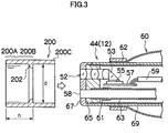
- the distal end portion 44 has a front surface 45 where an observation optical system 52, an illumination optical system 54, an air and water supply nozzle 56, and a forceps port (corresponds to a suction opening) 58 are provided.
- a prism 53 is mounted to the back of the observation optical system 52 as shown in Fig. 3 , so that a light path of a light from a subject obtained through the observation optical system 52 is bent downward by the prism 53.
- a CCD 55 which is supported by a substrate 57, and the light from a subject which was bent by the prism 53 is focused on a light sensitive surface of the CCD 55. Then the light from a subject is converted into an electrical signal by the CCD 55 to be transmitted through a signal cable 59.
- the signal cable 59 is inserted through into the inserting section 12, the hand held control section 14, the universal cable 16 and the like of Fig. 1 to be extended to the electric connector 24 which is connected to the processor 26.
- an observation image which is obtained by the observation optical system 52 is focused on a light sensitive surface of the CCD 55 to be converted into an electrical signal, which is output through a signal cable 59 to the processor 26 where the electrical signal is converted into an image signal.
- a picture image from observation is displayed on a monitor 50 which is in connection with the processor 26.
- light guides (not shown) are disposed with the outputting ends thereof.
- the light guides are inserted through into the inserting section 12, the hand held control section 14, the universal cable 16 and the like of Fig. 1 to dispose the inputting ends thereof in the LG connector 18.
- an illumination light irradiated from the light source device 20 is transmitted through the light guides to the illumination optical systems 54 to be irradiated forward from the illumination optical systems 54.
- the air and water supply nozzle 56 of Fig. 2 is in communicated with a valve (not shown) which is controlled by the air and water supply button 28 of Fig. 1 , and the valve is in turn in communicated with an air and water supply connector 48 which is provided in the LG connector 18.
- the air and water supply connector 48 is connected with an air and water supply device (not shown) to supply air or water.
- the forceps port 58 of Fig. 2 is in communicated with a pipe 61 which is supported by a distal end portion body 65 of Fig. 3 , and the pipe 61 is in turn coupled with a tube 63.
- the tube 63 is inserted through into the inserting section 12 of Fig. 1 to be in communicated with a forceps inserting section 46.
- a procedure tool such as a forceps
- the tube 63 of Fig. 3 is diverged along its way to be in communicated with a valve (not shown) which is controlled by the suction button 30 of Fig.
- the valve is in turn connected with a suction connector 49 of the LG connector 18.
- the suction connector 49 is connected with a suction pump (corresponds to a suction device) 51.
- Reference numeral 67 in Fig. 3 designates a cap mounted on the distal end surface of the distal end portion body 65
- reference numeral 69 designates a covering member which covers an outer circumferential surface of the inserting section 12.
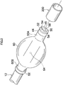
- a first balloon 60 is attached which is made of a resilient material such as rubber.
- the first balloon 60 is formed into a generally tubular shape having two deflated ends, and after the inserting section 12 is inserted through into the first balloon 60 and the first balloon 60 is disposed at a desired position, fixing rubber rings 62 are fit onto the both ends of the first balloon 60 so that the first balloon 60 is fixed around the inserting section 12.
- An air vent 64 is formed in the outer circumferential surface of the inserting section 12 where the first balloon 60 is attached.
- the air vent 64 is in communicated with the air inlet for balloon 38 which is provided in the hand held control section 14 of Fig. 1 .
- the air inlet for balloon 38 is connected to the balloon controlling device 100 via a tube 110.
- a supply or sucking air by the balloon controlling device 100 allows the first balloon 60 to be expanded or contracted.
- the first balloon 60 is expanded into a generally spherical shape by air supply, and is contracted to stick around the outer circumferential surface of the inserting section 12 by air suction.
- the insertion assisting tool 70 shown in Fig. 1 comprises a tubular and rigid holding section 72 which is provided at the rear end of the insertion assisting tool 70 and a tube body 73 which is attached to the distal end of the holding section 72, and the inserting section 12 of the endoscope 10 above described is inserted from the holding section 72 into the tube body 73.
- the tube body 73 comprises a flexible resin tube substrate which is formed of urethane for example, and the substrate has an outer circumferential surface and an inner circumferential surface which are coated by a hydrophilic coating material (a lubricant coating material).
- the hydrophilic coating material may be, for example, polyvinyl pyrrolidone.
- a second balloon 80 is attached near the distal end of the tube body 73.
- the second balloon 80 is formed into a tubular shape having two deflated ends, and is attached to the tube body 73 with the insertion assisting tool 70 being therethrough, and is fixed there by winding a thread (not shown) around the ends.
- the second balloon 80 is in communicated with a tube 74 which is adhered to the outer circumferential surface of the insertion assisting tool 70, and the tube 74 has a rear end to which a connector 76 is provided.
- the connector 76 is connected to a tube 120, and to the balloon controlling device 100 via the tube 120.
- a supply or sucking air by the balloon controlling device 100 allows the second balloon 80 to be expanded or contracted.
- the second balloon 80 is expanded into a generally spherical shape by air supply, and is contracted to stick around the outer circumferential surface of the insertion assisting tool 70 by air suction.
- the insertion assisting tool 70 has a rear end in which an inlet 78 is formed.
- the inlet 78 is in communicated with an opening (not shown) which is formed in the inner circumferential surface of the insertion assisting tool 70.
- a lubricant e.g. water
- the balloon controlling device 100 supplies and sucks in fluids such as air through the first balloon 60, and also supplies and sucks in fluids such as air to and from the second balloon 80.
- the balloon controlling device 100 generally comprises a device body 102 and a hand held switch 104 for remotely controlling.
- the device body 102 has a front side where a power switch SW1, a stop switch SW2, a first pressure indicator 106, a second pressure indicator 108, a first function stop switch SW3, and a second function stop switch SW4 are provided.
- Each of the first pressure indicator 106 and the second pressure indicator 108 is a panel to indicate a pressure value of the first balloon 60 and the second balloon 80 respectively, and the pressure indicators 106 and 108 indicate an error code in the event of failure such as a balloon burst.
- the first function stop switch SW3 and the second function stop switch SW4 turn on and off the functions of the control system for endoscope A and the control system for insertion assisting tool B which will be described below, respectively, and when only one of the first balloon 60 and the second balloon 80 is used, one of the function stop switches SW3 and SW4, not in use, is controlled to be turned off.
- the turned off control system A or B any supply and suction of air is completely stopped, and the pressure indicator 106 or 108 for the system is also turned off.
- the initial conditions of the systems may be set by turning off both of the function stop switches SW3 and SW4. For example, a calibration for an atmosphere pressure is performed by holding down all of the switches SW5 to SW9 simultaneously on the hand held switch 104 while both of the function stop switches SW3 and SW4 are turned off.
- Backflow prevention units 112 and 122 are provided at the points where each of the tubes 110 and 120 is connected to the device body 102, which prevent any backflow of body fluid when the first balloon 60 or the second balloon 80 is burst.
- the backflow prevention units 112 and 122 are respectively structured by fitting a filter for gas and liquid separation into the inside a hollow disk-like case (not shown) which is removably attached to the device body 102, so that the filter prevents any liquid flowing into the device body 102.
- the pressure indicators 106 and 108, the function stop switches SW3 and SW4, and the backflow prevention units 112 and 122 are fixedly arranged for the endoscope 10 and for the insertion assisting tool 70. That is, the pressure indicator 106, the function stop switch SW3, and the backflow prevention unit 112 are arranged for the endoscope 10 on the right side relative to the pressure indicator 108, the function stop switch SW4, and the backflow prevention units 122 for the insertion assisting tool 70, respectively.
- a stop switch SW5 which is similar to the stop switch SW2 on the device body 102, an ON/OFF switch SW6 to give a command to pressurize/depressurize the first balloon 60, a pose switch SW7 to maintain a pressure of the first balloon 60, an ON/OFF switch SW8 to give a command to pressurize/depressurize the second balloon 80, and a pose switch SW9 to maintain a pressure of the second balloon 80 are provided, and the hand held switch 104 is electrically connected to the device body 102 via a code 130. Also, display sections to display a condition of air supply or exhaust of the first balloon 60 and second balloon 80, which are not shown in Fig. 1 , are provided to the hand held switch 104.
- the balloon controlling device 100 configured as described above expands each balloon 60 and 80 by supplying air, and maintains the expanded balloons 60 and 80 by controlling the air pressure in the balloons at a constant value.
- the balloon controlling device 100 also contracts each balloon 60 and 80 by sucking air, and maintains the contracted balloons 60 and 80 by controlling the air pressure in the balloons at a constant value.
- the balloon controlling device 100 is connected to a balloon exclusive monitor 82 which displays a pressure value and an expanded or contracted condition of each balloon 60 and 80.
- a pressure value and an expanded or contracted condition of each balloon 60 and 80 may be displayed on the monitor 50 by superimposing on an observation image obtained by the endoscope 10.
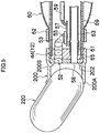
- a hood member 200 is applied to the distal end portion 44 of the inserting section 12 of the endoscope 10.
- the hood member 200 is formed of a resin or rubber into a cylindrical shape.
- the hood member 200 has an inner diameter d which is generally the same with or slightly smaller than the outer diameter of the distal end portion 44, thereby the hood member 200 is applied to the distal end portion 44 by elastically deforming a rear end of the hood member 200C to fit the hood member 200 onto the distal end portion 44.
- the hood member 200 has an opening at its distal end having an area larger than the opening area of the forceps port 58 in the distal end portion 44.
- the shape of the hood member 200 is not limited to a cylinder, and the hood member 200 may be formed into any shape such as a tapered shape. However, the opening at the distal end of the hood member 200 is preferably larger than the opening area of the forceps port 58.
- the hood member 200 has an inner circumferential surface having a position defining project 202 is formed to define a minimum projecting length of the hood, and the position defining project 202 contacts with the front surface of the inserting section 12 when the hood member 200 is attached to the distal end portion 44. This maintains the hood member 200 in a position projected from the distal end portion 44 when the hood member 200 is attached to the distal end portion 44.
- the position defining project 202 defines a minimum projecting length of the hood, the length may be increased as needed by an operator.
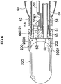
- the hood member 200 has a distal end portion 200A and a middle portion 200B, and the distal end portion 200A is formed of a material which is more flexible than that for the middle portion 200B.
- the distal end portion 200A of the hood member 200 elastically deforms when a medical capsule 220 is attracted by the vacuum inside of the hood member 200 to the distal end portion 200A of the hood member 200, which allows the medical capsule 220 to be reliably held. That is, as shown in Fig.
- the hood member 200 of this embodiment is configured to have the distal end portion 200A as a holding section to hold the medical capsule 220.
- the middle portion 200B is formed of a material which is less flexible than that of the distal end portion 200A, thereby the middle portion 200B of the hood member 200 keeps its original cylindrical shape when the inside of the hood member 200 is vacuum (or in a depressurized state). This prevents any crash of the middle portion 200B of the hood member 200, which in turn prevents the medical capsule 220 from falling.
- At least the middle portion 200B of the hood member 200 is formed of a transparent or semitransparent material.
- view is not restricted while the hood member 200 is inserted in a body cavity to find the medical capsule 220, and when the medical capsule 220 is held at the distal end portion 200A of the hood member 200, the outside of the hood member 200 can be observed through the transparent or semitransparent middle portion 200B.
- the entire of the hood member 200 may be formed of a transparent or semitransparent material.
- Figs. 6A to 6J show an example to insert an endoscopic apparatus by oral route, but the endoscopic apparatus may be inserted by anal route.
- the first balloon 60 and the second balloon 80 are contracted and the inserting section 12 is inserted into the insertion assisting tool 70 to start the insertion of the inserting section 12.
- the insertion assisting tool 70 is inserted along the inserting section 12, so that, as shown in Fig. 6B , the distal end of the insertion assisting tool 70 reaches the inside of the stomach 90A.
- the inserting section 12 is inserted into the insertion assisting tool 70 until the distal end of the inserting section 12 reaches the second portion of duodenum 90B as shown in Fig. 6C (an inserting operation). Then the first balloon 60 is expanded to fix the distal end of the inserting section 12 to the second portion of duodenum (a fixing operation).
- the insertion assisting tool 70 is pushed down to be inserted along the inserting section 12 (a pushing operation).
- the second balloon 80 is expanded by supplying air. This fixes the second balloon 80 to the second portion of duodenum 90B, which holds the second portion of duodenum 90B around the insertion assisting tool 70 via the second balloon 80 (a holding operation).
- both of the insertion assisting tool 70 and the inserting section 12 are drawn back (a drawing back operation). This removes any excess deflection or bending between the entrance and the second portion of duodenum 90B of the gastrointestinal tract 90.
- the inserting section 12 is inserted into the small intestine 90C (an inserting operation). Because any excess deflection or bending between the entrance and the second portion of duodenum 90B of the gastrointestinal tract 90 is already removed by the insertion assisting tool 70, the inserting section 12 can be readily inserted.
- the first balloon 60 is expanded to fix the distal end of the inserting section 12 to the gastrointestinal tract 90 (a fixing operation).
- the second balloon 80 is contracted, as shown in Fig. 6G , the insertion assisting tool 70 is pushed down to be inserted along the inserting section 12 (a pushing operation), so that the distal end of the insertion assisting tool 70 comes close to the first balloon 60 to expand the second balloon 80 (a holding operation).
- both of the insertion assisting tool 70 and the inserting section 12 are drawn back (a drawing back operation). This removes any excess deflection or bending of the gastrointestinal tract 90.
- the inserting section 12 is inserted into a body cavity with a hood member 200 being attached to the distal end portion 44 of the inserting section 12.
- a hood member 200 being attached to the distal end portion 44 of the inserting section 12.
- operations such as those described with Figs. 6A to 6J are performed to insert the distal end portion 44 of the inserting section 12 into a lower gastrointestinal tract such as small intestine.
- the distal end portion 44 of the inserting section 12 is inserted to a position where a medical capsule 220 is located, the distal end portion 200A of the hood member 200 is brought close to the medical capsule 220 in the body cavity while observing image obtained by the observation optical system 52.
- the suction button 30 is controlled to start a sucking through the forceps port 58. This causes the gas (or liquid) in the hood member 200 to be sucked through the forceps port 58, and the inside of the hood member 200 is made vacuum.
- the medical capsule 220 Due to the vacuum inside of the hood member 200, the medical capsule 220 is attracted to the distal end portion 200A of the hood member 200. As the distal end portion 200A of the hood member 200 is formed of a flexible material, the medical capsule 220 is reliably attracted to and held by the distal end portion 200A of the hood member 200, in spite of a posture of the medical capsule 220. Also, as the medical capsule 220 is attracted to and held by the distal opening of the hood member 200 the area of which is larger than that of the forceps port 58, the medical capsule 220 is reliably held with a larger holding power.
- the medical capsule 220 is held with a part of the medical capsule 220 being pulled into the inside of the hood member 200, which increases closeness due to increased airtightness between the medical capsule 220 and the hood member 200, so that the holding power for the medical capsule 220 is increased.
- the medical capsule 220 can be more reliably held.
- the inserting section 12 of the endoscope 10 is withdrawn out of the body cavity to bring the medical capsule 220 to the outside of the body cavity and collect it.
- the holding of the medical capsule 220 can be continuously checked visually from an observation image.
- the situation would be immediately known.
- the middle portion 200B of the hood member 200 is transparent or semitransparent, the outside of the hood member 200 can be observed. This prevents the held medical capsule 220 from being stuck to a wall surface and the like of the body cavity.
- the inside of the hood member 200 is sucked through the forceps port 58 to be vacuum, so that a medical capsule 220 is attracted to and held by the distal end portion 200A of the hood member 200. Because the distal end portion 200A of the hood member 200 has an opening the area of which is larger than that of the forceps port 58, the distal end portion 200A has a larger power to hold the medical capsule 220. So, according to this embodiment, the medical capsule 220 can be reliably held and collected without falling.
- the held medical capsule 220 can be continuously checked visually from an observation image obtained by the observation optical system 52.
- a hood member 206 shown in Fig. 7 includes a distal end portion 206A and a middle portion 206B, the distal end portion 206A having a thickness smaller than that of the middle portion 206B so that the distal end portion 206A is easily deflected. So, as shown in Fig. 8 , even when the hood member 206 approached the medical capsule 220 at an angle, the distal end portion 206A of the hood member 206 is deflected to closely contact with the medical capsule 220.
- the middle portion 206B of the hood member 206 of Fig. 7 and Fig. 8 is formed thicker than the distal end portion 206A with an inner circumferential surface of the middle portion 206B being projecting inward, and the middle portion 206B also functions as a positioning element when it contacts with the front surface 45 of the inserting section 12.
- the thick middle portion 206B keeps its original cylindrical shape even when the inside of the hood member 206 is sucked vacuum. This prevents the attracting power from being decreased due to a crash of the middle portion 206B, which in turn prevents the medical capsule 220 from falling.
- a hood member 208 shown in Fig. 9 has a distal end portion 208A and a middle portion 208B, and a groove 208D is formed between the distal end portion 208A and the middle portion 208B.
- the groove 208D is annularly formed in an inner circumferential surface of the hood member 208 in a circumferential direction thereof.
- the groove 208D of this configuration reduces the rigidity of the distal end portion 208A of the hood member 208, which allows the distal end portion 208A to be easily deflected. This increases closeness due to increased airtightness between the medical capsule 220 and the distal end portion 208A of the hood member 208, so that the holding power for the medical capsule 220 is increased.
- the medical capsule 220 can be reliably held. Especially, as shown in Fig. 10 , even when the hood member 208 approaches the medical capsule 220 at an angle, the distal end portion 208A of the hood member 208 is deflected to closely contact with the medical capsule 220, thereby the medical capsule 220 can be reliably held.
- a hood member 210 shown in Fig. 11 includes a distal end portion 210A having an outer circumferential surface provided with a plurality of grooves 210E.
- Each of the grooves 210E is formed in an axis direction of the hood member 210, and has a circular cross section which is perpendicular to the axis direction.
- the grooves 210E are separated by a uniform distance from each other in the circumferential direction, and ribs 210F are formed between the grooves 210E.
- the grooves 210E allow the distal end portion 210A of the hood member 210 to be easily deflected, and the ribs 210F allow the distal end portion 210A of the hood member 210 to maintain its appropriate rigidity.
- the grooves 210E formed in the outer circumferential surface make the inner circumferential surface smooth which readily contacts closely with a medical capsule 220. This increases closeness between the medical capsule 220 and the hood member 210, so that the medical capsule 220 can be more reliably held.
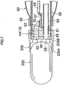
- a hood member 212 shown in Fig. 12 includes a distal end portion 212A having an inner circumferential surface which is formed to correspond to the curved shape of a medical capsule 220. That is, the distal end portion 212A of the hood member 212 has on its inner circumferential surface a curved surface portion 212G which corresponds to a part of the sphere of a medical capsule 220.
- the closeness between the medical capsule 220 and the distal end portion 212A of the hood member 212 is increased, so that the medical capsule 220 can be more reliably held.
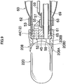
- a hood member 214 shown in Fig. 13 includes a distal end portion 214A having an inner circumferential surface which has a taper 214H to provide a holding section.
- the taper 214H contacts with the curved portion of the medical capsule 220, which increases closeness between the hood member 214 and the medical capsule 220, so that the medical capsule 220 can be more reliably held.
- a hood member 216 shown in Figs. 14 and 15 includes a distal end portion 216A which is provided with a circular groove 2161. The side of a medical capsule 220 is pulled into the groove 2161 to be held, so that the medical capsule 220 can be reliably held.
- a medical capsule 220 in a body cavity is held to be collected at outside of the body cavity, but the embodiment may be used in an application to transport a held medical capsule 220 through a body cavity.
- the embodiment may be used in an application to transport a held medical capsule 220 through a body cavity.
- a release of a medical capsule 220 is performed by controlling the suction button 30 of Fig. 1 to stop a sucking operation through the forceps port 58.
- the embodiment may be also used in an application to transport a medical capsule 220 into a body cavity by inserting the inserting section 12 into the body cavity after a medical capsule 220 is held by the inserting section 12 at the outside of the body cavity.
- a hood member 200 is attached to a distal end portion 44 of an inserting section 12 of an endoscope 10, and the inside of the hood member 200 is made vacuum through a forceps port 58 to attract a medical capsule 220 to the distal end of the hood member 200 so that the medical capsule 220 can be reliably held for its collection or transportation.
Landscapes
- Health & Medical Sciences (AREA)
- Life Sciences & Earth Sciences (AREA)
- Surgery (AREA)
- Biomedical Technology (AREA)
- Medical Informatics (AREA)
- Optics & Photonics (AREA)
- Pathology (AREA)
- Radiology & Medical Imaging (AREA)
- Biophysics (AREA)
- Engineering & Computer Science (AREA)
- Physics & Mathematics (AREA)
- Heart & Thoracic Surgery (AREA)
- Nuclear Medicine, Radiotherapy & Molecular Imaging (AREA)
- Molecular Biology (AREA)
- Animal Behavior & Ethology (AREA)
- General Health & Medical Sciences (AREA)
- Public Health (AREA)
- Veterinary Medicine (AREA)
- Gastroenterology & Hepatology (AREA)
- Endoscopes (AREA)
Claims (8)
- Endoskopvorrichtung, gekennzeichnet durch:ein Endoskop (10) mit einem Einführabschnitt (12) zum Einführen in einen Körperhohlraum, enthaltend ein distales Ende mit einem Betrachtungsabschnitt zum Betrachten eines Subjekts und mit einer Saugöffnung;eine Saugeinrichtung in Verbindung mit der Saugöffnung; undein Haubenelement (200), das an dem distalen Ende des Einführabschnitts (12) befestigt ist, und welches einen Halteabschnitt aufweist zum Anziehen und Halten einer medizinischen Kapsel (220), wenn die Saugeinrichtung betätigt wird, um das Innere des Haubenelements (200) über die Saugöffnung anzusaugen, damit das Innere des Haubenelements vakuumisiert wird,wobei das Haubenelement (200) im Wesentlichen zylindrisch ist, ein hinteres Ende (200C) aufweist, welches auf einer Außenumfangsfläche des Einführabschnitts (12) des Einführabschnitts (12) des Endoskops (10) passt, und ein distales Ende (200A) mit dem Halteabschnitt aufweist, wobei das Haubenelement (200) einen Mittelabschnitt (200B), einen distalen Endabschnitt (200A) aufweist, wobei der Mittelabschnitt (200B) transparent oder halbtransparent ist, dadurch gekennzeichnet,_ dass der distale Endabschnitt (200A) aus einem Material gebildet ist, welches flexibler ist als dasjenige des Mittelabschnitts (200B), und das sich entlang der medizinischen Kapsel (220) elastisch verformt.
- Endoskopvorrichtung nach Anspruch 1, dadurch gekennzeichnet, dass das Haubenelement (200) konfiguriert ist zum Halten einer medizinischen Kapsel (220), in dem mindestens ein Teil der medizinischen Kapsel (220) in das Innere des Haubenelements (200) gezogen wird.
- Endoskopvorrichtung nach einem der Ansprüche 1 bis 2, weiterhin gekennzeichnet durch:einen ersten ausdehnbaren und zusammenziehbaren Ballon (60), der an einer Außenumfangsfläche eines distalen Endes des Einführabschnitts (12) angebracht ist;ein Einführhilfswerkzeug, in welches der Einführabschnitt (12) zum Einführen in einen Körperhohlraum eingeführt wird; undeinen zweiten ausdehnbaren und zusammenziehbaren Ballon (80), der an einer Außenumfangsfläche des Einführhilfswerkzeugs angebracht ist.
- Endoskopvorrichtung nach einem der Ansprüche 1 bis 3, dadurch gekennzeichnet, dass
der Halteabschnitt ein distales Ende des Haubenelements (200) mit einer Innenumfangsfläche aufweist, die einen gekrümmten Abschnitt besitzt, entsprechend einer gekrümmten Form der medizinischen Kapsel (220). - Endoskopvorrichtung nach einem der Ansprüche 1 bis 3, dadurch gekennzeichnet, dass
der Halteabschnitt konfiguriert ist zum Enthalten eines distales Endes des Haubenelements (200), welches dünner ausgebildet ist als die übrigen Teile des Haubenelements (206). - Endoskopvorrichtung nach einem der Ansprüche 1 bis 6, dadurch gekennzeichnet, dass
der Halterabschnitt konfiguriert ist zum Enthalten eines distalen Endes eines Haubenelements (208) mit einer Innenumfangsfläche, in der in Umfangsrichtung eine Nut (208D) gebildet ist. - Endoskopvorrichtung nach einem der Ansprüche 1 bis 3, dadurch gekennzeichnet, dass
der Halteabschnitt konfiguriert ist zum Enthalten eines distalen Endes des Haubenelements (210) mit einer Außenumfangsfläche, in der eine Nut (210E) ausgebildet ist. - Endoskopvorrichtung nach Anspruch 7, dadurch gekennzeichnet, dass mehrere Nuten (210E) in einer Richtung entlang einer Mittelachse des Haubenelements (210) vorgesehen sind, wobei zwischen den Nuten Rippen (210F) gebildet sind.
Applications Claiming Priority (2)
| Application Number | Priority Date | Filing Date | Title |
|---|---|---|---|
| JP2005207535 | 2005-07-15 | ||
| JP2005278438A JP4776317B2 (ja) | 2005-07-15 | 2005-09-26 | 医療用カプセルの保持方法及びそれに用いる内視鏡装置 |
Publications (2)
| Publication Number | Publication Date |
|---|---|
| EP1743569A1 EP1743569A1 (de) | 2007-01-17 |
| EP1743569B1 true EP1743569B1 (de) | 2017-09-13 |
Family
ID=37162406
Family Applications (1)
| Application Number | Title | Priority Date | Filing Date |
|---|---|---|---|
| EP06014733.7A Active EP1743569B1 (de) | 2005-07-15 | 2006-07-14 | Endoskopvorrichtung zum Wiederaufnehmen/Transportieren einer medizinischen Kapsel |
Country Status (3)
| Country | Link |
|---|---|
| US (1) | US8012085B2 (de) |
| EP (1) | EP1743569B1 (de) |
| JP (1) | JP4776317B2 (de) |
Families Citing this family (17)
| Publication number | Priority date | Publication date | Assignee | Title |
|---|---|---|---|---|
| JP4929453B2 (ja) * | 2006-02-09 | 2012-05-09 | 国立大学法人 東京医科歯科大学 | 内視鏡用多目的処置フード及び内視鏡 |
| JP2008029527A (ja) * | 2006-07-27 | 2008-02-14 | Olympus Medical Systems Corp | 内視鏡システム |
| US7862542B1 (en) * | 2006-09-11 | 2011-01-04 | Harmon Sr James V | Flaccid tubular membrane and insertion appliance for surgical intubation and method |
| US9339174B2 (en) | 2007-07-18 | 2016-05-17 | Given Imaging Ltd | Device and method for viewing a body lumen |
| US10492662B2 (en) | 2012-03-27 | 2019-12-03 | Medigus Ltd. | Integrated endoscope irrigation |
| EP2830478B1 (de) * | 2012-03-27 | 2019-08-21 | Medigus Ltd. | Integrierte endoskopbewässerung |
| CN103156568A (zh) * | 2012-08-22 | 2013-06-19 | 武汉安康通光电技术有限公司 | 一种可释放和可磁控的细线管胶囊食道内窥镜 |
| TWI592128B (zh) * | 2016-06-03 | 2017-07-21 | 群曜醫電股份有限公司 | 內視鏡輔助裝置 |
| CN106773553B (zh) * | 2017-03-06 | 2018-11-30 | 重庆京东方光电科技有限公司 | 承载装置和曝光设备 |
| JP7120840B2 (ja) * | 2018-08-03 | 2022-08-17 | 株式会社シード | 内視鏡用フードの成形型 |
| USD1060669S1 (en) | 2019-04-09 | 2025-02-04 | AnX Robotica Corp | Tether for a capsule endoscope |
| US11786114B2 (en) * | 2019-04-09 | 2023-10-17 | AnX Robotica Corp | Systems and methods for liquid biopsy and drug delivery |
| JP2022530851A (ja) | 2019-05-01 | 2022-07-04 | スカウトカム リミテッド | 医療用眼科機装置 |
| CN110448340B (zh) * | 2019-07-25 | 2022-02-08 | 兖矿新里程总医院 | 一种子宫内膜采集装置 |
| CN111808916A (zh) | 2020-07-24 | 2020-10-23 | 上海安翰医疗技术有限公司 | 胰蛋白酶检测薄膜及其制备方法、应用和胰蛋白酶检测试剂盒 |
| EP3970641B1 (de) * | 2020-09-17 | 2025-04-23 | Gyrus ACMI, Inc. d/b/a Olympus Surgical Technologies America | Endoskopiespitzenverlängerer |
| US20230126325A1 (en) * | 2021-10-22 | 2023-04-27 | Gyrus Acmi, Inc. D/B/A Olympus Surgical Technologies America | Temporary anatomy illumination |
Citations (1)
| Publication number | Priority date | Publication date | Assignee | Title |
|---|---|---|---|---|
| US20020035311A1 (en) * | 2000-09-18 | 2002-03-21 | Asahi Kogaku Kogyo Kabushiki Kaisha | Tip portion of an endoscope |
Family Cites Families (25)
| Publication number | Priority date | Publication date | Assignee | Title |
|---|---|---|---|---|
| US4040413A (en) * | 1974-07-18 | 1977-08-09 | Fuji Photo Optical Co. Ltd. | Endoscope |
| JPS5529338A (en) * | 1978-08-22 | 1980-03-01 | Masazumi Takada | Flexible body cavity inside insertion appliance |
| JPS55143804A (en) * | 1979-04-24 | 1980-11-10 | Mitsubishi Electric Corp | Pulse count type frequency discriminator |
| JPS56143804A (en) | 1981-03-09 | 1981-11-09 | Kubota Ltd | Oleo hydraulic unit |
| JPS59183202A (ja) * | 1983-04-04 | 1984-10-18 | Hitachi Ltd | 低NO↓x燃焼器 |
| JPH02130601A (ja) * | 1988-11-11 | 1990-05-18 | Hitachi Ltd | 機器保護ユニット |
| US6620188B1 (en) * | 1998-08-24 | 2003-09-16 | Radiant Medical, Inc. | Methods and apparatus for regional and whole body temperature modification |
| US5462559A (en) * | 1993-02-23 | 1995-10-31 | Ahmed; Munir | Endoscopic ligating instrument |
| US5685823A (en) * | 1994-03-30 | 1997-11-11 | Asahi Kogaku Kogyo Kabushiki Kaisha | End structure of endoscope |
| US5653677A (en) * | 1994-04-12 | 1997-08-05 | Fuji Photo Optical Co. Ltd | Electronic endoscope apparatus with imaging unit separable therefrom |
| JPH08131397A (ja) * | 1994-11-14 | 1996-05-28 | Olympus Optical Co Ltd | 内視鏡用フード |
| JP3974235B2 (ja) * | 1997-10-06 | 2007-09-12 | ペンタックス株式会社 | 内視鏡の先端部 |
| IL122716A0 (en) | 1997-12-22 | 1998-08-16 | Tally Eitan Zeev Pearl And Co | System and method for in vivo delivery of autonomous capsule |
| AU4335700A (en) | 1999-04-07 | 2000-10-23 | Endonetics, Inc. | Implantable monitoring probe |
| US6752755B2 (en) * | 2000-08-07 | 2004-06-22 | Fuji Photo Optical Co., Ltd. | Endoscope and endoscope cap with recessed focal point |
| JP3668461B2 (ja) * | 2002-02-25 | 2005-07-06 | オリンパス株式会社 | 先端フード部材 |
| JP3791916B2 (ja) * | 2002-10-11 | 2006-06-28 | オリンパス株式会社 | 内視鏡用先端フード部材 |
| JP2004194976A (ja) * | 2002-12-19 | 2004-07-15 | Pentax Corp | 医療用カプセルの保持解放方法、導入方法及び回収方法 |
| US20040199052A1 (en) * | 2003-04-01 | 2004-10-07 | Scimed Life Systems, Inc. | Endoscopic imaging system |
| JP4311966B2 (ja) * | 2003-04-08 | 2009-08-12 | Hoya株式会社 | 医療用カプセル型内視鏡を保持及び解放可能な内視鏡システム |
| JP3888359B2 (ja) | 2003-05-15 | 2007-02-28 | 有限会社エスアールジェイ | 内視鏡装置 |
| JP4398184B2 (ja) * | 2003-06-24 | 2010-01-13 | オリンパス株式会社 | 内視鏡 |
| JP3772166B2 (ja) * | 2003-08-04 | 2006-05-10 | オリンパス株式会社 | 内視鏡のフード装置 |
| JP2005095582A (ja) * | 2003-08-21 | 2005-04-14 | Olympus Corp | 内視鏡用フード |
| US20050165272A1 (en) * | 2003-12-01 | 2005-07-28 | Yuta Okada | Endoscope system |
-
2005
- 2005-09-26 JP JP2005278438A patent/JP4776317B2/ja not_active Expired - Lifetime
-
2006
- 2006-07-03 US US11/478,709 patent/US8012085B2/en active Active
- 2006-07-14 EP EP06014733.7A patent/EP1743569B1/de active Active
Patent Citations (1)
| Publication number | Priority date | Publication date | Assignee | Title |
|---|---|---|---|---|
| US20020035311A1 (en) * | 2000-09-18 | 2002-03-21 | Asahi Kogaku Kogyo Kabushiki Kaisha | Tip portion of an endoscope |
Also Published As
| Publication number | Publication date |
|---|---|
| EP1743569A1 (de) | 2007-01-17 |
| JP2007044481A (ja) | 2007-02-22 |
| US8012085B2 (en) | 2011-09-06 |
| JP4776317B2 (ja) | 2011-09-21 |
| US20070015961A1 (en) | 2007-01-18 |
Similar Documents
| Publication | Publication Date | Title |
|---|---|---|
| EP1743569B1 (de) | Endoskopvorrichtung zum Wiederaufnehmen/Transportieren einer medizinischen Kapsel | |
| JP4000485B2 (ja) | 内視鏡装置 | |
| JP4149987B2 (ja) | 内視鏡装置 | |
| JP4665262B2 (ja) | 内視鏡用フード | |
| JP2008278968A (ja) | 内視鏡用挿入補助具 | |
| JP5171076B2 (ja) | 内視鏡装置 | |
| JP2005185309A (ja) | 内視鏡装置 | |
| EP1741381B1 (de) | Steuerungsvorrichtung für einen Ballon für Endoskop | |
| JP4874724B2 (ja) | 内視鏡装置 | |
| JP6147710B2 (ja) | 内視鏡用フード及び内視鏡システム | |
| JP4768365B2 (ja) | 内視鏡用の挿入補助具及び内視鏡装置 | |
| JP2006271863A (ja) | バルーン及びそれを装着した内視鏡、挿入補助具、並びに内視鏡装置 | |
| JP4977503B2 (ja) | 内視鏡 | |
| CN100413459C (zh) | 医疗用胶囊的回收、搬送方法以及在其中使用的内窥镜装置 | |
| JP4683282B2 (ja) | 内視鏡装置 | |
| JP2007089813A (ja) | 内視鏡装置 | |
| JP4786985B2 (ja) | 内視鏡 | |
| JP4710492B2 (ja) | 内視鏡装置 | |
| JP2007330468A (ja) | 内視鏡用カバー及びそれを備えた内視鏡装置 | |
| JP4665671B2 (ja) | 内視鏡装置 | |
| JP2007089812A (ja) | 内視鏡装置及び内視鏡用フード並びに医療用カプセルの搬送方法 | |
| JP3794497B1 (ja) | 内視鏡装置の挿入補助具及び挿入補助具を用いたバルーン装着方法 | |
| JP2007260287A (ja) | 内視鏡挿入補助具 | |
| JP5474914B2 (ja) | 挿入補助具の製造方法 | |
| JP2007260131A (ja) | 大腸内視鏡装置 |
Legal Events
| Date | Code | Title | Description |
|---|---|---|---|
| PUAI | Public reference made under article 153(3) epc to a published international application that has entered the european phase |
Free format text: ORIGINAL CODE: 0009012 |
|
| 17P | Request for examination filed |
Effective date: 20060714 |
|
| AK | Designated contracting states |
Kind code of ref document: A1 Designated state(s): AT BE BG CH CY CZ DE DK EE ES FI FR GB GR HU IE IS IT LI LT LU LV MC NL PL PT RO SE SI SK TR |
|
| AX | Request for extension of the european patent |
Extension state: AL BA HR MK YU |
|
| AKX | Designation fees paid |
Designated state(s): AT BE BG CH CY CZ DE DK EE ES FI FR GB GR HU IE IS IT LI LT LU LV MC NL PL PT RO SE SI SK TR |
|
| RAP1 | Party data changed (applicant data changed or rights of an application transferred) |
Owner name: SRJ CORPORATION Owner name: FUJIFILM CORPORATION |
|
| 17Q | First examination report despatched |
Effective date: 20160205 |
|
| GRAP | Despatch of communication of intention to grant a patent |
Free format text: ORIGINAL CODE: EPIDOSNIGR1 |
|
| INTG | Intention to grant announced |
Effective date: 20170420 |
|
| GRAS | Grant fee paid |
Free format text: ORIGINAL CODE: EPIDOSNIGR3 |
|
| GRAA | (expected) grant |
Free format text: ORIGINAL CODE: 0009210 |
|
| AK | Designated contracting states |
Kind code of ref document: B1 Designated state(s): AT BE BG CH CY CZ DE DK EE ES FI FR GB GR HU IE IS IT LI LT LU LV MC NL PL PT RO SE SI SK TR |
|
| REG | Reference to a national code |
Ref country code: GB Ref legal event code: FG4D |
|
| REG | Reference to a national code |
Ref country code: CH Ref legal event code: EP |
|
| REG | Reference to a national code |
Ref country code: IE Ref legal event code: FG4D |
|
| REG | Reference to a national code |
Ref country code: AT Ref legal event code: REF Ref document number: 927348 Country of ref document: AT Kind code of ref document: T Effective date: 20171015 |
|
| REG | Reference to a national code |
Ref country code: DE Ref legal event code: R096 Ref document number: 602006053600 Country of ref document: DE |
|
| REG | Reference to a national code |
Ref country code: NL Ref legal event code: MP Effective date: 20170913 |
|
| REG | Reference to a national code |
Ref country code: LT Ref legal event code: MG4D |
|
| PG25 | Lapsed in a contracting state [announced via postgrant information from national office to epo] |
Ref country code: FI Free format text: LAPSE BECAUSE OF FAILURE TO SUBMIT A TRANSLATION OF THE DESCRIPTION OR TO PAY THE FEE WITHIN THE PRESCRIBED TIME-LIMIT Effective date: 20170913 Ref country code: LT Free format text: LAPSE BECAUSE OF FAILURE TO SUBMIT A TRANSLATION OF THE DESCRIPTION OR TO PAY THE FEE WITHIN THE PRESCRIBED TIME-LIMIT Effective date: 20170913 Ref country code: SE Free format text: LAPSE BECAUSE OF FAILURE TO SUBMIT A TRANSLATION OF THE DESCRIPTION OR TO PAY THE FEE WITHIN THE PRESCRIBED TIME-LIMIT Effective date: 20170913 |
|
| REG | Reference to a national code |
Ref country code: AT Ref legal event code: MK05 Ref document number: 927348 Country of ref document: AT Kind code of ref document: T Effective date: 20170913 |
|
| PG25 | Lapsed in a contracting state [announced via postgrant information from national office to epo] |
Ref country code: BG Free format text: LAPSE BECAUSE OF FAILURE TO SUBMIT A TRANSLATION OF THE DESCRIPTION OR TO PAY THE FEE WITHIN THE PRESCRIBED TIME-LIMIT Effective date: 20171213 Ref country code: GR Free format text: LAPSE BECAUSE OF FAILURE TO SUBMIT A TRANSLATION OF THE DESCRIPTION OR TO PAY THE FEE WITHIN THE PRESCRIBED TIME-LIMIT Effective date: 20171214 Ref country code: LV Free format text: LAPSE BECAUSE OF FAILURE TO SUBMIT A TRANSLATION OF THE DESCRIPTION OR TO PAY THE FEE WITHIN THE PRESCRIBED TIME-LIMIT Effective date: 20170913 Ref country code: ES Free format text: LAPSE BECAUSE OF FAILURE TO SUBMIT A TRANSLATION OF THE DESCRIPTION OR TO PAY THE FEE WITHIN THE PRESCRIBED TIME-LIMIT Effective date: 20170913 |
|
| PG25 | Lapsed in a contracting state [announced via postgrant information from national office to epo] |
Ref country code: NL Free format text: LAPSE BECAUSE OF FAILURE TO SUBMIT A TRANSLATION OF THE DESCRIPTION OR TO PAY THE FEE WITHIN THE PRESCRIBED TIME-LIMIT Effective date: 20170913 |
|
| PG25 | Lapsed in a contracting state [announced via postgrant information from national office to epo] |
Ref country code: PL Free format text: LAPSE BECAUSE OF FAILURE TO SUBMIT A TRANSLATION OF THE DESCRIPTION OR TO PAY THE FEE WITHIN THE PRESCRIBED TIME-LIMIT Effective date: 20170913 Ref country code: RO Free format text: LAPSE BECAUSE OF FAILURE TO SUBMIT A TRANSLATION OF THE DESCRIPTION OR TO PAY THE FEE WITHIN THE PRESCRIBED TIME-LIMIT Effective date: 20170913 Ref country code: CZ Free format text: LAPSE BECAUSE OF FAILURE TO SUBMIT A TRANSLATION OF THE DESCRIPTION OR TO PAY THE FEE WITHIN THE PRESCRIBED TIME-LIMIT Effective date: 20170913 |
|
| PG25 | Lapsed in a contracting state [announced via postgrant information from national office to epo] |
Ref country code: SK Free format text: LAPSE BECAUSE OF FAILURE TO SUBMIT A TRANSLATION OF THE DESCRIPTION OR TO PAY THE FEE WITHIN THE PRESCRIBED TIME-LIMIT Effective date: 20170913 Ref country code: AT Free format text: LAPSE BECAUSE OF FAILURE TO SUBMIT A TRANSLATION OF THE DESCRIPTION OR TO PAY THE FEE WITHIN THE PRESCRIBED TIME-LIMIT Effective date: 20170913 Ref country code: EE Free format text: LAPSE BECAUSE OF FAILURE TO SUBMIT A TRANSLATION OF THE DESCRIPTION OR TO PAY THE FEE WITHIN THE PRESCRIBED TIME-LIMIT Effective date: 20170913 Ref country code: IS Free format text: LAPSE BECAUSE OF FAILURE TO SUBMIT A TRANSLATION OF THE DESCRIPTION OR TO PAY THE FEE WITHIN THE PRESCRIBED TIME-LIMIT Effective date: 20180113 Ref country code: IT Free format text: LAPSE BECAUSE OF FAILURE TO SUBMIT A TRANSLATION OF THE DESCRIPTION OR TO PAY THE FEE WITHIN THE PRESCRIBED TIME-LIMIT Effective date: 20170913 |
|
| REG | Reference to a national code |
Ref country code: FR Ref legal event code: PLFP Year of fee payment: 13 |
|
| REG | Reference to a national code |
Ref country code: DE Ref legal event code: R097 Ref document number: 602006053600 Country of ref document: DE |
|
| PLBE | No opposition filed within time limit |
Free format text: ORIGINAL CODE: 0009261 |
|
| STAA | Information on the status of an ep patent application or granted ep patent |
Free format text: STATUS: NO OPPOSITION FILED WITHIN TIME LIMIT |
|
| PG25 | Lapsed in a contracting state [announced via postgrant information from national office to epo] |
Ref country code: DK Free format text: LAPSE BECAUSE OF FAILURE TO SUBMIT A TRANSLATION OF THE DESCRIPTION OR TO PAY THE FEE WITHIN THE PRESCRIBED TIME-LIMIT Effective date: 20170913 |
|
| 26N | No opposition filed |
Effective date: 20180614 |
|
| PG25 | Lapsed in a contracting state [announced via postgrant information from national office to epo] |
Ref country code: SI Free format text: LAPSE BECAUSE OF FAILURE TO SUBMIT A TRANSLATION OF THE DESCRIPTION OR TO PAY THE FEE WITHIN THE PRESCRIBED TIME-LIMIT Effective date: 20170913 |
|
| REG | Reference to a national code |
Ref country code: CH Ref legal event code: PL |
|
| PG25 | Lapsed in a contracting state [announced via postgrant information from national office to epo] |
Ref country code: LU Free format text: LAPSE BECAUSE OF NON-PAYMENT OF DUE FEES Effective date: 20180714 Ref country code: MC Free format text: LAPSE BECAUSE OF FAILURE TO SUBMIT A TRANSLATION OF THE DESCRIPTION OR TO PAY THE FEE WITHIN THE PRESCRIBED TIME-LIMIT Effective date: 20170913 |
|
| REG | Reference to a national code |
Ref country code: BE Ref legal event code: MM Effective date: 20180731 |
|
| REG | Reference to a national code |
Ref country code: IE Ref legal event code: MM4A |
|
| PG25 | Lapsed in a contracting state [announced via postgrant information from national office to epo] |
Ref country code: IE Free format text: LAPSE BECAUSE OF NON-PAYMENT OF DUE FEES Effective date: 20180714 Ref country code: LI Free format text: LAPSE BECAUSE OF NON-PAYMENT OF DUE FEES Effective date: 20180731 Ref country code: CH Free format text: LAPSE BECAUSE OF NON-PAYMENT OF DUE FEES Effective date: 20180731 |
|
| PG25 | Lapsed in a contracting state [announced via postgrant information from national office to epo] |
Ref country code: BE Free format text: LAPSE BECAUSE OF NON-PAYMENT OF DUE FEES Effective date: 20180731 |
|
| PG25 | Lapsed in a contracting state [announced via postgrant information from national office to epo] |
Ref country code: TR Free format text: LAPSE BECAUSE OF FAILURE TO SUBMIT A TRANSLATION OF THE DESCRIPTION OR TO PAY THE FEE WITHIN THE PRESCRIBED TIME-LIMIT Effective date: 20170913 |
|
| PG25 | Lapsed in a contracting state [announced via postgrant information from national office to epo] |
Ref country code: PT Free format text: LAPSE BECAUSE OF FAILURE TO SUBMIT A TRANSLATION OF THE DESCRIPTION OR TO PAY THE FEE WITHIN THE PRESCRIBED TIME-LIMIT Effective date: 20170913 Ref country code: HU Free format text: LAPSE BECAUSE OF FAILURE TO SUBMIT A TRANSLATION OF THE DESCRIPTION OR TO PAY THE FEE WITHIN THE PRESCRIBED TIME-LIMIT; INVALID AB INITIO Effective date: 20060714 |
|
| PG25 | Lapsed in a contracting state [announced via postgrant information from national office to epo] |
Ref country code: CY Free format text: LAPSE BECAUSE OF FAILURE TO SUBMIT A TRANSLATION OF THE DESCRIPTION OR TO PAY THE FEE WITHIN THE PRESCRIBED TIME-LIMIT Effective date: 20170913 |
|
| PGFP | Annual fee paid to national office [announced via postgrant information from national office to epo] |
Ref country code: GB Payment date: 20250529 Year of fee payment: 20 |
|
| PGFP | Annual fee paid to national office [announced via postgrant information from national office to epo] |
Ref country code: FR Payment date: 20250610 Year of fee payment: 20 |
|
| PGFP | Annual fee paid to national office [announced via postgrant information from national office to epo] |
Ref country code: DE Payment date: 20250528 Year of fee payment: 20 |