EP1738123B1 - Dispositif et procede de transformation par voie seche - Google Patents
Dispositif et procede de transformation par voie seche Download PDFInfo
- Publication number
- EP1738123B1 EP1738123B1 EP05713000A EP05713000A EP1738123B1 EP 1738123 B1 EP1738123 B1 EP 1738123B1 EP 05713000 A EP05713000 A EP 05713000A EP 05713000 A EP05713000 A EP 05713000A EP 1738123 B1 EP1738123 B1 EP 1738123B1
- Authority
- EP
- European Patent Office
- Prior art keywords
- gas
- substrate
- enclosure
- average
- close
- Prior art date
- Legal status (The legal status is an assumption and is not a legal conclusion. Google has not performed a legal analysis and makes no representation as to the accuracy of the status listed.)
- Not-in-force
Links
Images

Classifications
-
- F—MECHANICAL ENGINEERING; LIGHTING; HEATING; WEAPONS; BLASTING
- F26—DRYING
- F26B—DRYING SOLID MATERIALS OR OBJECTS BY REMOVING LIQUID THEREFROM
- F26B13/00—Machines and apparatus for drying fabrics, fibres, yarns, or other materials in long lengths, with progressive movement
-
- F—MECHANICAL ENGINEERING; LIGHTING; HEATING; WEAPONS; BLASTING
- F26—DRYING
- F26B—DRYING SOLID MATERIALS OR OBJECTS BY REMOVING LIQUID THEREFROM
- F26B13/00—Machines and apparatus for drying fabrics, fibres, yarns, or other materials in long lengths, with progressive movement
- F26B13/005—Seals, locks, e.g. gas barriers for web drying enclosures
-
- F—MECHANICAL ENGINEERING; LIGHTING; HEATING; WEAPONS; BLASTING
- F26—DRYING
- F26B—DRYING SOLID MATERIALS OR OBJECTS BY REMOVING LIQUID THEREFROM
- F26B13/00—Machines and apparatus for drying fabrics, fibres, yarns, or other materials in long lengths, with progressive movement
- F26B13/10—Arrangements for feeding, heating or supporting materials; Controlling movement, tension or position of materials
-
- F—MECHANICAL ENGINEERING; LIGHTING; HEATING; WEAPONS; BLASTING
- F26—DRYING
- F26B—DRYING SOLID MATERIALS OR OBJECTS BY REMOVING LIQUID THEREFROM
- F26B25/00—Details of general application not covered by group F26B21/00 or F26B23/00
- F26B25/005—Treatment of dryer exhaust gases
- F26B25/006—Separating volatiles, e.g. recovering solvents from dryer exhaust gases
Definitions
- This invention relates to processes and equipment for converting moving substrates of indefinite length.
- Moving substrates of indefinite length can be converted in a variety of ways from one state or shape to another state or shape.
- Some converting processes produce considerable debris, or are carried out in the presence of airborne particulates or other contaminants, or may require a controlled environment when ordinary ambient air conditions might disrupt the converting process or pose a safety hazard.
- This can be a particular problem in dry converting operations, when static buildup may cause debris, particulates or other contaminants to adhere to the moving substrate.
- optical-grade coatings on plastic films are especially sensitive to contamination, which may cause visible defects.
- Typical controlled environments include clean rooms and the use of inert, low oxygen or saturated atmospheres. Clean rooms and special atmospheres require costly auxiliary equipment and large volumes of filtered air or specialty gases. For example, a typical clean room operation may require many thousands of liters per minute of filtered air.
- GB-A-2 079 913 and US-A-5 333 395 disclose drying ovens for wet substrates.
- DE 42 43 515 A1 describes a low-leakage air lock at the entry and/or exit of a treatment section for web lines. However, no arrangements are made in order to minimize the sealed volume, e.g. by the use of a close enclosure.
- the disclosed invention includes a process and apparatus for dry converting a moving substrate of indefinite length in a controlled environment using low volumes of filtered air or specialty gases.
- the disclosed process and apparatus utilize a close enclosure that envelopes the moving substrate during at least the converting operation, the close enclosure being supplied with one or more streams of conditioned gas flowing at a rate sufficient to reduce materially the close enclosure particle count.
- the invention thus provides in one aspect a process for dry converting a moving substrate of indefinite length comprising conveying the substrate through a dry converting station in a close enclosure while supplying the enclosure with one or more streams of conditioned gas flowing at a rate sufficient to reduce materially the particle count in the close enclosure.
- the invention provides in another aspect an apparatus for converting a moving substrate of indefinite length comprising a dry converting station and substrate-handling equipment for conveying the substrate through the dry converting station, the substrate being enveloped in the dry converting station by a close enclosure supplied with one or more streams of conditioned gas flowing at a rate sufficient to reduce materially the particle count in the close enclosure.
- the invention provides in yet another aspect a process for dry converting a moving substrate of indefinite length comprising conveying the substrate through a dry converting station in a close enclosure while supplying the enclosure with one or more streams of conditioned gas flowing at a rate sufficient to cause a material change in a physical property of interest for the atmosphere in the close enclosure.
- the invention provides in yet another aspect an apparatus for converting a moving substrate of indefinite length comprising a dry converting station and substrate-handling equipment for conveying the substrate through the dry converting station, the substrate being enveloped in the dry converting station by a close enclosure supplied with one or more streams of conditioned gas flowing at a rate sufficient to cause a material change in a physical property of interest for the atmosphere in the close enclosure.
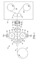
- Fig. 1 is a schematic side sectional view of a disclosed slitting/cleaning apparatus.
- Fig. 2 is a schematic side sectional view of a disclosed laminating apparatus.
- Fig. 3 is a schematic side sectional view of a disclosed close enclosure.
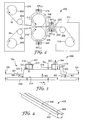
- Fig. 4 is a perspective view of a disclosed distribution manifold.
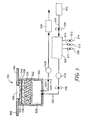
- Fig. 5 is a partial schematic, partial cross sectional view of the distribution manifold of Fig. 4 and associated conditioned gas supply and gas withdrawal components.
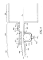
- Fig. 6 is a schematic cross sectional view of a transport roll and distribution manifold.
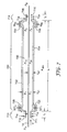
- Fig. 7 is a schematic side sectional view of another disclosed close enclosure.
- Fig. 8 is a schematic cross sectional view of the close enclosure of Fig. 7 .
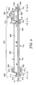
- Fig. 9 is a schematic side sectional view of another disclosed close enclosure.
- Fig. 10 is a schematic plan view of the overlying control surface in Fig. 9 .
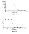
- Fig. 11 is a graph showing particle count versus pressure in a disclosed close enclosure.
- Fig. 12 is a graph showing oxygen level versus pressure in a disclosed close enclosure.
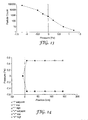
- Fig.13 is a graph showing particle count versus pressure in a disclosed close enclosure.
- Fig. 14 is a graph showing pressures at various positions within a disclosed close enclosure.
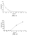
- Fig. 15 is a graph showing pressure versus web slot height for a disclosed close enclosure.
- Fig. 16 is a graph showing particle count versus web slot height for a disclosed close enclosure.
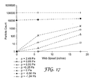
- Fig. 17 is a graph showing particle count versus web speed at various pressures for a disclosed close enclosure.
- Dry converting refers to an operation carried out without applying or drying a wet coating on the substrate, wherein the operation changes the substrate's cleanliness state, surface energy, shape, thickness, crystallinity, elasticity or transparency. Dry converting may include, for example, operations such as cleaning (e.g., plasma treating or the use of tacky rolls), electrically priming (e.g., corona-treating), slitting, cutting into pieces, splitting (e.g., stripping into sheets), laminating, stretching (e.g., orienting), folding (e.g., corrugating), thermoforming, masking, demasking, vapor coating, heating or cooling.
- cleaning e.g., plasma treating or the use of tacky rolls
- electrically priming e.g., corona-treating
- slitting e.g., cutting into pieces
- splitting e.g., stripping into sheets
- laminating e.g., stretching into sheets
- laminating stretching (e.g.,
- dry converting station refers to a device that carries out dry converting.
- downstream and upstream refer respectively to the direction of substrate motion and its opposite direction.
- leading and trailing refer respectively to regions at which the substrate enters or exits the recited apparatus, component or station.
- width refers to the length perpendicular to the direction of substrate motion and in the plane of the substrate.
- web-handling equipment refers to a device or devices that transport the substrate through the apparatus.
- control surface refers to a surface that is generally parallel to a major face of the substrate and located sufficiently close to the substrate so that an atmosphere that may affect the substrate is present between the control surface and the substrate.
- a control surface may include for example an enclosure housing, a separate plate, the walls of a slit, or other surface having an appreciable area generally parallel to a major face of the substrate.
- the word "overlying" refers to an apparatus, component or station that would be above the substrate if the substrate is envisioned in a horizontal orientation.
- the word "underlying" refers to an apparatus, component or station that would be below the substrate if the substrate is envisioned in a horizontal orientation.
- the word “headspace” refers to the distance from the substrate to an overlying nearby control surface measured perpendicular to the substrate if the substrate is envisioned in a horizontal orientation.
- footspace refers to the distance from the substrate to an underlying nearby control surface measured perpendicular to the substrate if the substrate is envisioned in a horizontal orientation.
- close enclosure refers to an enclosure whose average headspace plus average footspace throughout the enclosure is no greater than about 30 cm.
- conditioned gas refers to gas that is different from the ambient air surrounding the apparatus in at least one property of interest.
- particle count refers to the number of 0.5 ⁇ m or larger particles in a volume of 28.3 liters.
- the word "material” refers to at least a 50% reduction or increase in the property of interest compared to the ambient air surrounding the apparatus, component or station.
- negative pressure refers to pressure below that of the ambient air surrounding the apparatus, component or station
- positive pressure refers to a pressure above that of the ambient air surrounding the apparatus, component or station
- pressure gradient refers to a pressure differential between an interior portion of the apparatus, component or station and that of the ambient air surrounding the apparatus, component or station.
- Unwind reel 12 supplies web 14 to slitter blades 16.
- Unwind reel 12 may optionally be enclosed in a suitable cabinet may be unventilated, ventilated with ambient air, or supplied with a suitable conditioned gas stream as desired.
- Edge vacuums 18 remove contamination from the outer and slit edges of web 14, and rubber rolls 20 and tacky rolls 22 remove contamination from the major faces of web 14.
- Static eliminator bars 24 remove charge from web 14. After passing over transfer rolls 27, the slit portions of web 14 are individually wound on take-up reels 28 located inside cabinet 33.
- Cabinet 33 typically does not benefit from employing a close enclosure, and instead desirably has a sufficiently roomy and uncluttered interior to house the slit web rolls and permit easy roll changeover and transport.
- Cabinet 33 may be unventilated, ventilated with ambient air, or supplied with a suitable conditioned gas stream as desired.
- the slitter/cleaner components are enveloped by a close enclosure 10 formed by overlying housing 30 and underlying housing 32. Housings 30, 32 may conform closely to the shape of the slitter/cleaner components to provide a reduced interior atmosphere and reduced interior volume. A further close enclosure and transition zone formed by overlying control surface 25 and underlying control surface 26 is interconnected to close enclosure 10 and is connected to cabinet 33. Upper and lower manifolds 34 and 36 respectively may provide gas flows into or out of the apparatus (e.g., conditioned gas streams M1' U and M1' L ) at a point downstream from the slitter/cleaner components.
- conditioned gas streams M1' U and M1' L conditioned gas streams
- Conditioned gas streams M1' U and M1' L desirably differ from the ambient air by having a lower particle count, but may in addition or instead differ in another property of interest, e.g., a different chemical composition due to the absence or presence of one or more gases (including humidity) or a different temperature.
- Upper and lower manifolds 38 and 40 respectively may provide gas flows into or out of close enclosure 10 (e.g., withdrawn gas streams M4 U and M4 L ).
- Fig. 2 shows a schematic side sectional view of laminator 200.
- Unwind reels 202 and transfer rolls 204 are located inside cabinet 205.
- Cabinet 205 may be unventilated, ventilated with ambient air, or supplied with a suitable conditioned gas stream as desired.
- Webs 14 and 16 pass over transfer rolls 204, between lamination rolls 206, over transfer roll 208 and onto takeup roll 210 inside cabinet 211.
- Cabinet 211 may be unventilated, ventilated with ambient air, or supplied with a suitable conditioned gas stream as desired.
- the lamination rolls 206 are enveloped by a close enclosure formed by overlying housing 212 and underlying housing 214. This close enclosure is connected to cabinet 211.
- Housings 212, 214 may conform closely to the shape of the rolls 206 to provide a reduced interior atmosphere and reduced interior volume.
- a further close enclosure and transition zone formed by overlying control surface 215 and underlying control surface 216 is interconnected to the close enclosure formed by housings 212, 214 and is connected to cabinet 211.
- Upper manifolds 218, 222 and lower manifolds 220, 224 respectively may provide gas flows into or out of the apparatus (e.g., conditioned gas streams M1' U1 , M1' U2 , M1' L1 and M1' L2 ).
- One or more of conditioned gas streams M1' U1 , M1' U2 , M1' L1 and M1' L2 desirably differ from the ambient air by having a lower particle count, but may in addition or instead differ in another property of interest, e.g., a different chemical composition due to the absence or presence of one or more gases (including humidity) or a different temperature.
- the disclosed process and apparatus do not need to employ all the close enclosures shown in Fig. 1 and Fig. 2 , and may employ different close enclosures or processes than those shown or more close enclosures or processes than those shown.
- Two or more of the disclosed close enclosures may be interconnected in series in a web process thereby creating multiple successive zones or applications.
- Each individual close enclosure may be operated at different pressures, temperatures and headspace or footspace gaps to address process and material variants.
- Individual close enclosures may have none, one or more than one conditioned gas inputs or gas withdrawal devices. A positive pressure could be maintained or established in some close enclosures and a negative pressure in other close enclosures.
- interconnected close enclosures For processes in which cleanliness is a concern, use of interconnected close enclosures is recommended from at least the first point at which debris or other contaminants may arise or pose a problem (e.g., after a slitter or before lamination rolls) up to at least a station at which debris or other contaminants may no longer pose a problem.
- Such interconnection can provide continuous protection that may reduce substrate contamination and facilitate control of the particle count in the atmosphere immediately surrounding the substrate while using only small volumes of conditioned gases.
- Additional control of converting conditions may be achieved by employing a close enclosure or series of interconnected close enclosures from at least the first dry converting station in a process, or from at least the first point at which debris or other contaminants may arise or pose a problem, up to or through at least the last dry converting station in a process (e.g., a cutting, slitting or folding station). Additional control may also be achieved by employing a close enclosure from the first dry converting station in a process (e.g., a cleaning or priming station) up to or through at least the last dry converting station in the process, up to a takeup reel or up to a packaging station.
- a close enclosure or series of interconnected close enclosures from at least the first dry converting station in a process, or from at least the first point at which debris or other contaminants may arise or pose a problem, up to or through at least the last dry converting station in a process (e.g., a cutting, slitting or folding station). Additional control may also be achieved by employing
- the coated substrate is not exposed to ambient air from at least the time the substrate is unwound until it has been wound on a takeup reel or packaged.
- the disclosed apparatus may also include one or more sections that do not represent a close enclosure, but desirably the number, total volume and gas flow patterns of such sections is such that undesirable contamination of the substrate does not arise.
- conditioned gas streams could be injected (or gas could be withdrawn) at more or fewer locations than are shown in Fig. 1 and Fig. 2 .
- a conditioned gas stream could be injected at the first of several interconnected close enclosures, and the conditioned gas could be carried along with the moving substrate to the downstream close enclosures or pushed to an upstream enclosure or process.
- conditioned gas streams could be injected wherever needed to maintain or establish a slight positive pressure in each of several interconnected close enclosures.
- conditioned gas streams could be injected where needed to maintain or establish a slight positive pressure in some of several interconnected close enclosures, and a slight negative or zero pressure could be maintained or established in other interconnected close enclosures.
- conditioned gas streams could be injected at each of several interconnected close enclosures.
- a cleanroom could optionally surround the disclosed apparatus. However, this could be of a much lower classification and much smaller volume than that which might typically be used today.
- the cleanroom could be a portable model using flexible hanging panel materials.
- web support systems that will be familiar to those skilled in the art may be employed in the disclosed process and apparatus, including porous air tubes, air bars, and air foils.
- a moving substrate of indefinite length has at least one major surface with an adjacent gas phase.
- the substrate is treated with an apparatus having a control surface in close proximity to a surface of the substrate to define a control gap between the substrate and the control surface.
- the control gap may be referred to as the headspace or footspace between the substrate and the nearby control surface.
- a first chamber may be positioned near a control surface, with the first chamber having a gas introduction device.
- a second chamber may be positioned near a control surface, the second chamber having a gas withdrawal device.
- the control surface and the chambers together define a region wherein the adjacent gas phases possess an amount of mass. At least a portion of the mass from the adjacent gas phases is transported through the gas withdrawal device by inducing a flow through the region.
- the mass flow can be segmented into the following components:
- Fig. 3 is a schematic side sectional view of a close enclosure 300.
- a substrate 312 has at least one major surface 314 with an adjacent gas phase (not shown in Fig. 3 ).
- the substrate 312 is in motion in the direction of arrow "V" under a control surface 315, thus defining a control gap "G C ".
- a first chamber 317 having a gas introduction device 318 is positioned near the control surface 315.
- the exact form of the gas introduction device 318 may vary, and expedients such as a gas knife, a gas curtain, or a gas manifold can be used.
- first chamber 317 in the form of a plenum
- gas introduction device 318 be positioned at a remove from the level of control surface 315.
- a second chamber 319 is also positioned near the control surface 315, and has a gas withdrawal device 320.
- the illustrated embodiment depicts the second chamber 319 in the form of a plenum, it is not necessary that the gas withdrawal device 320 be positioned at the level of control surface 315.
- the first chamber 317 and the second chamber 319 will be at opposing ends of the control surface 315 as depicted in Fig. 3 .
- the first chamber 317 defines a first gap G1 between the first chamber 317 and the substrate 312.
- the second chamber 319 defines a second gap G2 between the second chamber 319 and the substrate 312.
- the first gap G1, the second gap G2, and the control gap G C are all of equal height, however in other embodiments, at least one of the first gap G1 or the second gap G2 has a height different than the control gap G C . Best results appear to be achieved when the first gap, second gap and control gap are all 10 cm or less. In some exemplary embodiments the first gap, the second gap, and the control gap are all 5 cm or less, 3 cm or less, or even smaller values, e.g., 2 cm or less, 1.5 cm or less, or 0.75 cm or less.
- the airflow required to attain a desired low particle count may vary in part with the square of the combined headspace and footspace, and accordingly the disclosed gaps desirably have relatively small values. Similarly, best results appear to be achieved when the total of the average headspace and average footspace is 10 cm or less, 5 cm or less, 3 cm or less, or even smaller values, e.g., 2 cm or less, 1.5 cm or less, or 0.75 cm or less.
- control of the atmosphere near the substrate may also be aided by using mechanical features, such as extensions 323 and 325 in Fig. 3 .
- the extensions 323 and 325, having gaps G3 and G4 may be added to one of both of the upstream or downstream ends of the apparatus.
- the extensions may be affixed to various members of the apparatus or provided with alternate shapes depending on the specific embodiment selected for a particular purpose.
- Flows M1 and M3 may be reduced as the substrate area "covered" by the extensions increases.
- the adjacent gas phase between the control surface 315, first chamber 317, second chamber 319 and the surface 314 of the substrate 312 define a region possessing an amount of mass.
- the extensions 323 and 325 may further define the region under the control surface having an adjacent gas phase possessing an amount of mass.
- the mass in the region is generally in a gas phase.
- the region may also contain mass that is in either the liquid or solid phase, or combinations of all three phases.
- Fig. 3 depicts the various flow streams encountered in close enclosure 300 when practicing the disclosed process.
- M1 is the total net time-average mass flow per unit width into or out of the region resulting from pressure gradients.
- M1 is a signed number, negative when it represents a small outflow from the region as the drawing depicts, and positive when it represents a small inflow into the region, opposing the depicted arrows.
- Positive values of M1 essentially represent a dilution stream and possible source of contaminants that desirably are reduced and more desirably are made negative for the overall portion of the apparatus constituting interconnected close enclosures.
- M1' is the total net time-average mass flow of conditioned gas per unit width into the region from gas introduction device 318.
- M1' reduces the particle count in the close enclosure. Excessively high M1' flows desirably are avoided in order to limit disturbance of substrate 312.
- M2 is the time-average mass flow per unit width from or into at least one major surface of the substrate into the region and through the chamber. M2 essentially represents evolution of volatile species or other material from substrate 312 into close enclosure 300.
- M3 is the total net time-average mass flow per unit width into the region and through the chamber resulting from motion of the substrate. M3 essentially represents gas swept along with the substrate in its motion.
- M4 is the time-average rate of mass transported per unit width through the gas withdrawal device 320. M4 represents the sum of M1 + M1' + M2 + M3.
- Mass flow through a close enclosure may be assisted by employing a suitable seal with respect to the moving substrate ( viz ., a "moving substrate seal") at an upstream or downstream inlet or outlet of a close enclosure or connected chain of close enclosures.
- the seal may function as a sweep to prevent gas from entering or exiting the close enclosures.
- the seal could also include for example a forced gas, mechanical or retractable mechanical seal such as those shown in U.S. Patent No. 6,553,689 , or a pair of opposed nip rolls.
- a retractable mechanical sealing mechanism can allow passage of splices and other upset conditions. It may be desirable briefly to increase one or more nearby conditioned gas flow rates (or to decrease or switch one or more nearby gas withdrawal rates) to maintain the desired atmosphere near the seal.
- a pair of opposed nip rolls may be located for example, upstream or downs stream from the first or last dry converting station in a process.
- a material particle count reduction may be obtained within a close enclosure.
- An exemplary pressure gradient is at least about -0.5 Pa or higher ( viz ., a more positive value).
- Another exemplary pressure gradient is a positive pressure gradient.
- the disclosed process and apparatus may also substantially reduce the dilution gas flow, M1, transported through the chamber.
- the disclosed process and apparatus may, for example, limit M1 to an absolute value not greater than 0.25 kg/second/meter.
- M1 may be, for example, less than zero (in other words, representative of net outflow from the close enclosure) and greater than -0.25 kg/second/meter. In another exemplary embodiment, M1 may be less than zero and greater than -0.1 kg/second/meter.
- small negative enclosure pressures (which may correspond to slight positive M1 flows) can be tolerated.
- large negative enclosure pressures (which may correspond to large positive M1 flows) may cause adverse effects including dilution of mass in the adjacent gas phase, introduction of particles and other airborne contaminants, and introduction of uncontrolled ingredients, temperatures or humidity.
- a process by appropriately controlling M1' and M4.
- a deliberate influx of a conditioned gas stream e.g., a clean, inert gas having a controlled humidity
- M1' By carefully controlling the volume and conditions under which M1' is introduced and M4 is withdrawn (and for example by maintaining a slight positive pressure in the close enclosure), flow M1 can be significantly curtailed and the close enclosure particle count can be significantly reduced.
- the M1' stream may contain reactive or other components or optionally at least some components recycled from M4.
- the headspace or footspace may be substantially uniform from the upstream end to the downstream end and across the width of the close enclosure.
- the headspace or footspace may also be varied or non-uniform for specific applications.
- the close enclosure may have a width wider than the substrate and desirably will have closed sides that further reduce time-average mass flow per unit width from pressure gradients (M1).
- M1 pressure gradients
- the close enclosure can also be designed to conform to different geometry material surfaces. For example, the close enclosure can have a radiused periphery to conform to the surface of a cylinder.
- the close enclosure may also include one or more mechanisms to control the phase of the mass transported through the close enclosure thereby controlling phase change of the components in the mass.
- conventional temperature control devices may be incorporated into the close enclosure to prevent condensate from forming on the internal portions of the close enclosure.
- suitable temperature control devices include heating coils, electrical heaters, external heat sources and heat transfer fluids.
- the withdrawn gas stream (M4) may be vented or filtered and vented after exiting the close enclosure.
- the gas phase composition may flow from one or more of the close enclosures to a subsequent processing location, e.g., without dilution.
- the subsequent processing may include such optional steps as, for example, separation or destruction of one or more components in the gas phase.
- the collected vapor stream may contain particulate matter which can be filtered prior to the separation process. Separation processing may also occur internally within the close enclosure in a controlled manner. Suitable separation or destruction processes will be familiar to those skilled in the art.
- FIG. 4 is a perspective view of a disclosed distribution manifold 400 that can assist in providing an even flow of supplied conditioned gas (M1').
- Manifold 400 has a housing 402, and mounting flanges 404 flanking slit 406. Further details regarding manifold 400 are shown in Fig. 5 , which is a schematic partial cross sectional view of manifold 400 and an associated gas conditioning system.
- Gas source 502 supplies a suitable gas (e.g., nitrogen or an inert gas) to gas conditioning system 508 via line 504 and valve 506.
- System 508 is optionally supplied with additional reactive species via lines 510, 512 and 514 and valves 511, 513 and 515.
- System 508 supplies the desired conditioned gas stream to manifold 400 via line 520, valve 516 and flow sensor 518.
- Vacuum line 522 may be used to withdraw gas from manifold 400 via flow sensor 524, valve 526 and vacuum pump 528.
- the presence of both a supply line and a vacuum line enables manifold 400 to be used as a conditioned gas introduction or gas withdrawal device.
- Gases entering manifold 400 pass through head space 520, around diverter plate 532, and through distribution media 534 (made, e.g., using white SCOTCHBRITETM nonwoven fabric, commercially available from 3M Co.), and then pass through a first perforated plate 536, HEPA filter media 538 and a second perforated plate 540 before entering slit 406.
- Gasket 542 helps maintain a seal between flanges 404 and perforated plate 540.
- Manifold 400 can help supply a substantially uniform flow of supplied conditioned gas across the width of a close enclosure.
- the pressure drop laterally in the head space 520 is negligible in comparison to the pressure drop through the remaining components of manifold 400.
- the dimensions or shape of head space 520 and the pore size of distribution media 534 may be adjusted as needed to vary the flow rate across the length of distribution manifold 400 and along the width of a close enclosure.
- the flow rate along the length of distribution manifold 400 can also be adjusted by using an array of bolts or other suitable devices arranged to bear against diverter plate 532 and compress distribution media 534, thereby adjustably varying the pressure drop along the length of distribution manifold 400.
- Fig. 6 shows a close enclosure in the form of a transition zone 600 coupled at its upstream end to a process 602 having underlying control surface 604 and overlying control surface 606 .
- the downstream end of transition zone 600 is coupled to process 608 operating at a pressure pB.
- Gaskets 610 provide a seal at each end of transition zone 600 and permit removal of the overlying or underlying control surfaces for, e.g., cleaning or web threadup.
- Transition zone 600 has a fixed overlying control surface 611 and a positionable overlying control surface 612 (shown in phantom in its raised position 613) that may be manually or automatically actuated to provide headspace values of h2a, h2b and values in between.
- Upper distribution manifold 614 may be used to supply conditioned gas stream M1' U .
- the underlying side of transition zone 600 has transport roll 616 inside housing 618, and underlying control surface 620.
- Lower distribution manifold 622 may be used to supply conditioned gas stream M1' L .
- Transition zone 600 may be helpful in discouraging large gas flows between adjacent connected processes involving a material difference in respective operating pressures. Foe example, in some processes there may be a two-fold or greater, five-fold or greater or even ten-fold or greater pressure difference between processes at either end of the disclosed close enclosure and transition zone.
- Fig. 7 and Fig. 8 respectively show a schematic sectional view and a cross sectional view of a close enclosure 700 having overlying control surface 702, underlying control surface 704 and sides 706 and 708.
- Close enclosure 700 has length l e and width w e .
- Web 14 has width w, and is transported through close enclosure 700 at velocity V.
- Gaskets 709 provide a seal at the sides of overlying control surface 702 and permit its height adjustment or removal (e.g., for cleaning or web threadup).
- Overlying control surface 702 and underlying control surface 704 are spaced apart a distance h e1 .
- Underlying control surface 704 is spaced apart from substrate 14 a distance h e2 . These distances may vary in the upstream or downstream directions.
- Upstream transition zone 710 has underlying and overlying web slot pieces 711 and 712. These web slot pieces are spaced apart a distance h 1a , and have length l 1 . Underlying web slot piece 711 is spaced apart from web 14 a distance h 1b .
- An upstream process (not shown in Fig. 7 or Fig. 8 ) is in direct gaseous communication with transition zone 710 and has pressure P A .
- Downstream transition zone 714 has underlying and overlying web slot pieces 716 and 718. These web slot pieces are spaced apart a distance h 2a , and have length l 2 . Underlying web slot piece 716 is spaced apart from web 14 a distance h 2b .
- a downstream process (not shown in Fig.
- transition zone 7 or Fig. 8 is in direct gaseous communication with transition zone 714 and has pressure P B .
- the transition zones between the upstream or downstream process and the close enclosure may utilize additional dilution (or exhaust) streams to decrease the pressure differential between the process and the close enclosure.
- convection ovens often operate at large negative pressures (-25 Pa is not uncommon), inducing large gas flows.
- Upper and lower manifolds 720 and 722 respectively may provide gas flows into or out of the upstream end of close enclosure 700 (e.g., conditioned gas streams M1' U and M1' L ).
- Upper and lower manifolds 724 and 726 respectively may provide gas flows into or out of the upstream end of close enclosure 700 (e.g., withdrawn gas streams M4 U and M4 L ).
- the pressures inside the enclosure can be characterized by P 1 , P 2 , P 13 , P 23 , P 3 and P 4 .
- the ambient air pressure outside close enclosure 700 is given by P atm .
- the disclosed process and apparatus typically will utilize a web handling system to transport a moving substrate of indefinite length through the apparatus.
- a web handling system to transport a moving substrate of indefinite length through the apparatus.
- suitable material handling systems and devices including, for example, a polymer, woven or non-woven material, fibers, powder, paper, a food product, pharmaceutical product or combinations thereof.
- the disclosed process and apparatus may also be used, for example to clean or prime a substrate prior to the application of a coating, as described in copending U.S. Patent Application Serial No. (Attorney docket number 55752US018), filed even date herewith and entitled "COATING PROCESS AND APPARATUS".
- exemplary embodiments of the disclosed apparatus can significantly reduce the particle count in the atmosphere surrounding a moving web.
- Exemplary embodiments of the disclosed apparatus may also capture at least a portion of a vapor component from a substrate (if present) without substantial dilution and without condensation of the vapor component.
- the supplied conditioned gas may significantly reduce the introduction of particulates into portions of the apparatus surrounding the substrate and thus may reduce or prevent product quality problems in the finished product.
- the relatively low air flow may significantly reduce disturbances to the substrate and thus may further reduce or prevent product quality problems.
- FIG. 9 shows a schematic side sectional view of a close enclosure 900.
- Close enclosure 900 has overlying control surface 902, underlying control surface 904 and side 906 equipped with sample ports A, B and C for measuring pressure, particle count and oxygen levels within close enclosure 900.
- Overlying control surface 902 and underlying control surface 904 are spaced apart a distance h e1 .
- Underlying control surface 904 is spaced apart from substrate 14 a distance h e2 .
- Upstream transition zone 908 has underlying and overlying web slot pieces 910 and 912. These web slot pieces are spaced apart a distance h 1a , and have length l 1 .
- Underlying web slot piece 910 is spaced apart from web 14 a distance h 1b .
- Downstream transition zone 914 has underlying and overlying web slot pieces 916 and 918. These web slot pieces are spaced apart a distance h 2a , and have length l 2 .
- Underlying web slot piece 916 is spaced apart from web 14 a distance h 2b .
- Upper and lower distribution manifolds 920 and 922 respectively supply conditioned gas streams M1' U and M1' L , at the upstream end of close enclosure 900. Web 14 is transported through close enclosure 900 at velocity V.
- Downstream process 924 has movable underlying control surface 926, overlying control surface 928 equipped with ambient gas inlet 930 and vacuum outlet 932, and underlying and overlying web slot pieces 926 and 928. These web slot pieces are spaced apart a distance h B1 . Underlying web slot piece 926 is spaced apart from web 14 a distance h B2 . These web slot pieces have length l 3 .
- close enclosure 900 was used with an uncoated web and was not connected at either its upstream or downstream ends to another close enclosure.
- the surrounding room with a defined ambient pressure of zero, lies upstream from transition zone 908 and downstream from process 924.
- the room air temperature was about 20° C.
- Fig. 10 shows a plan view of overlying control surface 902.
- Surface 902 has length l e and width w e , and contains 5 rows of 3 numbered holes each having a 9.78 mm diameter and a 0.75 cm 2 area, with the lowest numbered holes located at the upstream end of control surface 902.
- the holes can be used as sample ports for measuring pressure, particle count and oxygen levels at different locations within the enclosure and may also be left open or taped closed to vary the open draft area of close enclosure 900.
- Particle counts were measured using a MET ONETM Model 200L-1-115-1 Laser Particle Counter (commercially available from Met One Instruments, Inc.), to determine the number of 0.5 ⁇ m or larger particles in a volume of 28.3 liters, at a 28.3 liters/min flow rate. Pressures were measured using a Model MP40D micromanometer (commercially available from Air-Neotronics Ltd.). Oxygen levels were measured using a IST-AIMTM Model 4601 Gas Detector (commercially available from Imaging and Sensing Technology Corporation). Gas velocities were evaluated using a Series 490 Mini Anemometer (commercially available from Kurz Instruments, Inc.).
- Upper and lower distribution manifolds 920 and 922 were connected to a nitrogen supply and the flow rates adjusted using DWYERTM Model RMB-56-SSV flow meters (commercially available from Dwyer Instruments, Inc.). Vacuum outlet 932 was connected to a NORTECTM Model 7 compressed air driven vacuum pump (commercially available from Nortec Industries, Inc.). The flow rate was adjusted using a pressure regulator and a DWYER Model RMB-106 flow meter (commercially available from Dwyer Instruments, Inc.).
- Example 1 was repeated using an 18 m/minute web velocity V .
- the particle count results are shown in Fig. 13 (which uses a logarithmic particle count scale).
- Fig.13 demonstrates that for a moving web, material particle count reductions were obtained, at, e.g., pressures greater than -0.5 Pa.
- a - 0.5 Pa enclosure pressure was obtained in close enclosure 900 by adjusting the flow rates M1' U and M1' L , to 24 liters/min and by adjusting the rate of gas withdrawal at outlet 932 to 94 liters/min.
- a +0.5 Pa enclosure pressure was obtained by adjusting the flow rates M1' U and M1' L , to 122 liters/min and by adjusting the rate of gas withdrawal at outlet 932 to 94 liters/min.
- the respective particle counts were 107,889 at -0.5 Pa, and only 1 at +0.5 Pa.
- the enclosure pressure above the substrate was measured at several points along the length of close enclosure 900 using holes 2, 5, 8, 11 and 14 (see Fig.
- Example 2 Using the general method of Example 1, the M1' U and M1' L , flow rates were set at 122 liters/min and the rate of gas withdrawal at outlet 932 was set at 94 liters/min.
- the web slot height h 1a was adjusted to values of 0, 0.46, 0.91, 1.27, 2.54 and 3.81 cm.
- the ambient air particle count was 111,175.
- Fig. 16 and Fig. 17 (which both use linear vertical axis scales) respectively show the pressure and particle count inside the enclosure at various web slot heights. In all instances, a material particle count reduction (compared to the ambient air particle count) was obtained.
- Example 2 Using the general method of Example 1 and a 23 cm wide polyester film substrate moving at 0, 6 or 18 m/min, the M1' U and M1' L , flow rates and the rate of gas withdrawal at outlet 932 were adjusted to obtain varying enclosures pressures.
- the ambient air particle count was 111,175.
- the enclosure particle count was measured as a function of web speed and enclosure pressure.
- Fig.18 (which uses a logarithmic particle count scale).
- Fig. 18 demonstrates that material particle count reductions were obtained for all measured substrate speeds at, e.g., pressures greater than -0.5 Pa.
Claims (14)
- Procédé de transformation par voie sèche d'un substrat mobile (14) de longueur indéfinie, comprenant le transport du substrat à travers une station de transformation par voie sèche dans une enceinte fermée (10, 25, 26, 30, 32, 212, 214) dont l'espace de tête moyen plus l'espace de pied moyen de la totalité de l'enceinte n'est pas supérieur à environ 30 cm, tout en alimentant l'enceinte avec un ou plusieurs courant(s) de gaz conditionné (M1'U, M1'U1, M1'U2, M1'L, M1'L1, M1'L2) qui s'écoule(nt) avec un débit suffisant pour entraîner un changement matériel consistant en une diminution ou une augmentation d'au moins 50 % d'une propriété physique ayant une importance pour l'atmosphère dans l'enceinte fermée comparativement à l'air ambiant qui entoure la station.
- Procédé selon la revendication 1, comprenant la fourniture de gaz conditionné avec un débit suffisant pour réduire matériellement le nombre de particules dans l'enceinte fermée, dans lequel le nombre de particules fait référence au nombre de particules de 0,5 µm ou plus dans un volume de 28,3 litres.
- Procédé selon la revendication 2, comprenant le transport du substrat dans une enceinte fermée ou une série d'enceintes fermées à travers au moins une première station de transformation par voie sèche dans le procédé.
- Procédé selon la revendication 3, dans lequel au moins deux enceintes fermées dans la série d'enceintes fermées présentent des pressions différentes, des températures différentes, des espaces de tête moyens différents ou des espaces de pied moyens différents.
- Procédé selon la revendication 2, comprenant la connexion d'une première enceinte et d'une deuxième enceinte présentant une différence matérielle entre leurs pressions de service respectives par l'intermédiaire d'une enceinte fermée comprenant une zone de transition, dans lequel il y a une différence de pression de dix fois ou plus entre les atmosphères dans les première et deuxième enceintes.
- Procédé selon la revendication 2, dans lequel une première chambre (317) équipée d'un dispositif d'introduction de gaz (318) est positionnée à proximité d'une surface de commande (315), une deuxième chambre (319) équipée d'un dispositif d'extraction de gaz (320) est positionnée à proximité de la surface de commande (315), la surface de commande (315) et les première et deuxième chambres (317, 319) définissent ensemble une région dans laquelle dans laquelle des phases gazeuses adjacentes possèdent une quantité de masse, au moins une partie de la masse issue des phases gazeuses adjacentes est transportée à travers le dispositif d'extraction de gaz (320) en induisant un écoulement à travers la région, et le débit massique peut être segmenté en les composantes suivantes:M1 désigne le débit massique moyen temporel net total par unité de largeur de substrat (312) dans ou hors de la région résultant de gradients de pression;M1' désigne le débit massique moyen temporel net total d'un gaz par unité de largeur dans la région à travers la première chambre (317) à partir du dispositif d'introduction de gaz (318);M2 désigne le débit massique moyen temporel de gaz conditionné par unité de largeur à partir de ou dans ladite au moins une surface majeure du substrat (312) dans ou à partir de la région;M3 désigne le débit massique moyen temporel net total par unité de largeur dans la région résultant du déplacement de la matière; etM4 désigne le débit moyen temporel de transport de masse à travers le dispositif d'extraction de gaz (320) par unité de largeur.
- Procédé selon la revendication 2, comprenant l'écoulement d'un courant de gaz conditionné avec un débit suffisant pour réduire un nombre de particules dans l'enceinte fermée de 75 % ou plus.
- Dispositif de transformation d'un substrat mobile (14) de longueur indéfinie comprenant une station de transformation par voie sèche et un équipement de manipulation de substrat pour transporter le substrat à travers la station de transformation par voie sèche, le substrat étant enveloppé dans la station de transformation par voie sèche par une enceinte fermée (10, 25, 26, 30, 32, 212, 214) dont l'espace de tête moyen plus l'espace de pied moyen de la totalité de l'enceinte n'est pas supérieur à environ 30 cm, alimentée avec un ou plusieurs courant(s) de gaz conditionné (M1'U, M1'U1, M1'U2, M1'L, M1'L1, M1'L2) qui s'écoule(nt) avec un débit suffisant pour entraîner un changement matériel consistant en une diminution ou une augmentation d'au moins 50 % d'une propriété physique ayant une importance pour l'atmosphère dans l'enceinte fermée comparativement à l'air ambiant qui entoure la station.
- Dispositif selon la revendication 8, dans lequel le gaz conditionné s'écoule avec un débit suffisant pour réduire matériellement le nombre de particules dans l'enceinte fermée, le nombre de particules faisant référence au nombre de particules de 0,5 µm ou plus dans un volume de 28,3 litres.
- Dispositif selon la revendication 9, dans lequel une première chambre équipée d'un dispositif d'introduction de gaz est positionnée à proximité d'une surface de commande, une deuxième chambre équipée d'un dispositif d'extraction de gaz est positionnée à proximité de la surface de commande, la surface de commande et les première et deuxième chambres définissent ensemble une région dans laquelle des phases gazeuses possèdent une quantité de masse, au moins une partie de la masse issue des phases gazeuses adjacentes peut être transportée à travers le dispositif d'extraction de gaz en induisant un écoulement à travers la région, et le débit massique peut être segmenté en les composantes suivantes:M1 désigne le débit massique moyen temporel net total par unité de largeur de substrat dans ou hors de la région résultant de gradients de pression;M1' désigne le débit massique moyen temporel net total d'un gaz par unité de largeur dans la région à travers la première chambre à partir du dispositif d'introduction de gaz;M2 désigne le débit massique moyen temporel de gaz conditionné par unité de largeur à partir de ou dans ladite au moins une surface majeure du substrat dans ou à partir de la région;M3 désigne le débit massique moyen temporel net total par unité de largeur dans la région résultant du déplacement de la matière; etM4 désigne le débit moyen temporel de transport de masse à travers le dispositif d'extraction de gaz par unité de largeur.
- Procédé selon la revendication 2 ou dispositif selon la revendication 9, dans lequel le total de l'espace de tête moyen et de l'espace de pied moyen dans l'enceinte fermée est de 10 cm ou moins.
- Procédé selon la revendication 2 ou dispositif selon la revendication 9, dans lequel le total de l'espace de tête moyen et de l'espace de pied moyen dans l'enceinte fermée est de 5 cm ou moins.
- Procédé selon la revendication 2 ou dispositif selon la revendication 9, dans lequel le total de l'espace de tête moyen et de l'espace de pied moyen dans l'enceinte fermée est de 3 cm ou moins.
- Procédé selon la revendication 2, comprenant des courants d'écoulement de gaz conditionné avec un débit suffisant pour réduire le nombre de particules dans l'enceinte fermée de 90 % ou plus.
Applications Claiming Priority (2)
| Application Number | Priority Date | Filing Date | Title |
|---|---|---|---|
| US10/810,065 US7143528B2 (en) | 2000-09-24 | 2004-03-26 | Dry converting process and apparatus |
| PCT/US2005/003786 WO2005103591A1 (fr) | 2004-03-26 | 2005-02-04 | Dispositif et procede de transformation par voie seche |
Publications (2)
| Publication Number | Publication Date |
|---|---|
| EP1738123A1 EP1738123A1 (fr) | 2007-01-03 |
| EP1738123B1 true EP1738123B1 (fr) | 2009-09-23 |
Family
ID=34960622
Family Applications (1)
| Application Number | Title | Priority Date | Filing Date |
|---|---|---|---|
| EP05713000A Not-in-force EP1738123B1 (fr) | 2004-03-26 | 2005-02-04 | Dispositif et procede de transformation par voie seche |
Country Status (9)
| Country | Link |
|---|---|
| US (2) | US7143528B2 (fr) |
| EP (1) | EP1738123B1 (fr) |
| JP (1) | JP4634440B2 (fr) |
| KR (1) | KR101177953B1 (fr) |
| CN (1) | CN1957216B (fr) |
| AT (1) | ATE443837T1 (fr) |
| BR (1) | BRPI0509183A (fr) |
| DE (1) | DE602005016788D1 (fr) |
| WO (1) | WO2005103591A1 (fr) |
Families Citing this family (9)
| Publication number | Priority date | Publication date | Assignee | Title |
|---|---|---|---|---|
| US7143528B2 (en) * | 2000-09-24 | 2006-12-05 | 3M Innovative Properties Company | Dry converting process and apparatus |
| US7877895B2 (en) * | 2006-06-26 | 2011-02-01 | Tokyo Electron Limited | Substrate processing apparatus |
| US20070080613A1 (en) * | 2006-09-20 | 2007-04-12 | Sterlite Optical Technologies Ltd | Storage and transportation device for storing and transporting optical fiber preform and precursors thereof |
| JP4901395B2 (ja) * | 2006-09-26 | 2012-03-21 | 富士フイルム株式会社 | 塗布膜の乾燥方法 |
| WO2010033758A1 (fr) * | 2008-09-18 | 2010-03-25 | Nordson Corporation | Système automatisé d’amorçage à robinet assisté par dépression et ses procédés d’utilisation |
| CN102326233B (zh) | 2008-12-31 | 2013-11-20 | 3M创新有限公司 | 制备设备元件的方法以及所得的元件和设备 |
| WO2013023058A2 (fr) * | 2011-08-11 | 2013-02-14 | Avery Dennison Corporation | Séchoir à plaques inversées et procédé de séchage de revêtement à base de solvant |
| CN108033297A (zh) * | 2018-01-08 | 2018-05-15 | 天津中钢联科技发展有限公司 | 一种加强型热轧钢带 |
| CN217172649U (zh) * | 2022-02-28 | 2022-08-12 | 宁德时代新能源科技股份有限公司 | 一种穿带装置及烘烤设备 |
Family Cites Families (65)
| Publication number | Priority date | Publication date | Assignee | Title |
|---|---|---|---|---|
| US1494830A (en) | 1923-08-20 | 1924-05-20 | Robert W Cook | Process of manufacturing cellulose acetate |
| DE499308C (de) | 1927-06-29 | 1930-06-05 | Hermann Und Alfred Escher Akt | Einrichtung zur Rueckgewinnung von fluechtigen Loesungsmitteln bei mit Bandbahn arbeitenden Maschinen und Trockenapparaten |
| US2157388A (en) | 1937-01-22 | 1939-05-09 | Interchem Corp | Method of printing and setting a printing ink |
| GB713612A (en) | 1951-10-29 | 1954-08-11 | Petrus Vial | Process and apparatus for the recovery of solvents on long webs |
| BE530378A (fr) | 1953-08-20 | 1900-01-01 | ||
| US3071869A (en) | 1958-10-16 | 1963-01-08 | Time Inc | Web drying apparatus |
| US3408748A (en) | 1966-08-17 | 1968-11-05 | Dow Chemical Co | Drying and recovery process |
| US3542640A (en) * | 1967-03-23 | 1970-11-24 | Procter & Gamble | Method for drying a wet foam containing cellulosic fibers |
| US3452447A (en) | 1967-05-25 | 1969-07-01 | Thomas A Gardner | Web positioning means and method |
| AT321257B (de) | 1971-05-26 | 1975-03-25 | Koreska Gmbh W | Anlage zur Rückgewinnung flüchtiger Lösungsmittel |
| US3931684A (en) | 1973-10-15 | 1976-01-13 | J. J. Baker Company Limited | Vapor chamber for drying |
| US4051278A (en) | 1975-06-06 | 1977-09-27 | Eastman Kodak Company | Method for reducing mottle in coating a support with a liquid coating composition |
| US4012847A (en) | 1975-11-24 | 1977-03-22 | Autosonics Inc. | Solvent recovery system |
| US4053990A (en) | 1976-03-03 | 1977-10-18 | Sav-Sol Drying Systems, Inc. | Differential pressure drying and solvent recovery unit |
| US4263724A (en) | 1979-06-14 | 1981-04-28 | Vits-Maschinenbau Gmbh | Traveling web drying apparatus |
| US4223450A (en) | 1979-07-05 | 1980-09-23 | Airco, Inc. | Methods and apparatus for controlling gas flows |
| US4268977A (en) | 1979-12-03 | 1981-05-26 | Exxon Research & Engineering Company | Sealing apparatus for ovens |
| US4287240A (en) | 1980-04-11 | 1981-09-01 | Eastman Kodak Company | Coating apparatus provided with a protective shield |
| GB2079913A (en) | 1980-05-09 | 1982-01-27 | Crosfield Electronics Ltd | Web drying apparatus |
| US4365423A (en) * | 1981-03-27 | 1982-12-28 | Eastman Kodak Company | Method and apparatus for drying coated sheet material |
| US4369584A (en) | 1981-04-16 | 1983-01-25 | W. R. Grace & Co. | Preventing air film between web and roller |
| US4462169A (en) | 1982-02-19 | 1984-07-31 | W. R. Grace & Company | Web dryer solvent vapor control means |
| US4926567A (en) | 1985-07-04 | 1990-05-22 | Fuji Photo Film Co., Ltd. | Process and apparatus for drying coated web |
| SE458065B (sv) | 1986-10-16 | 1989-02-20 | Tore Eklund | Parabolantennfaeste som aer roerligt foer instaellning saavael foer utstraeckning i lodplanet som foer vinkel instaellning i lodplanet |
| JPS63158166A (ja) | 1986-12-23 | 1988-07-01 | Fuji Photo Film Co Ltd | 帯状物の乾燥方法 |
| US4752217A (en) | 1987-08-28 | 1988-06-21 | Essex Group, Inc. | Wire coating oven including wire cooling apparatus |
| FI78756C (fi) | 1988-04-25 | 1989-09-11 | Valmet Paper Machinery Inc | Foerfarande och anordning vid torkning av en roerlig bana. |
| JPH0248132Y2 (fr) | 1988-09-16 | 1990-12-18 | ||
| DE4009797A1 (de) | 1990-03-27 | 1991-10-02 | Pagendarm Gmbh | Verfahren und anordnung zum kondensieren von dampffoermigen substanzen |
| US5248349A (en) * | 1992-05-12 | 1993-09-28 | Solar Cells, Inc. | Process for making photovoltaic devices and resultant product |
| DE4226107A1 (de) | 1992-08-07 | 1994-02-10 | Vits Maschinenbau Gmbh | Trocknungsanlage |
| DE4243515A1 (de) | 1992-12-22 | 1994-06-23 | Basf Magnetics Gmbh | Abdichtvorrichtung am Einlauf und Auslauf einer Behandlungsstrecke für Warenbahnen |
| US6117237A (en) | 1994-01-04 | 2000-09-12 | 3M Innovative Properties Company | Coater die enclosure system |
| US5524363A (en) * | 1995-01-04 | 1996-06-11 | W. R. Grace & Co.-Conn. | In-line processing of a heated and reacting continuous sheet of material |
| US5555635A (en) * | 1995-01-18 | 1996-09-17 | W. R. Grace & Co.-Conn. | Control and arrangement of a continuous process for an industrial dryer |
| JP3616171B2 (ja) | 1995-09-04 | 2005-02-02 | 富士写真フイルム株式会社 | 長尺状光学補償シートの製造方法 |
| US5853801A (en) | 1995-09-04 | 1998-12-29 | Fuji Photo Film Co., Ltd. | Process for the preparation of continuous optical compensatory sheet |
| DE69617257T2 (de) | 1995-09-18 | 2002-06-13 | Minnesota Mining & Mfg | Komponenttrennungssystem mit kondensierungsmechanismus |
| US5694701A (en) | 1996-09-04 | 1997-12-09 | Minnesota Mining And Manufacturing Company | Coated substrate drying system |
| US5581905A (en) | 1995-09-18 | 1996-12-10 | Minnesota Mining And Manufacturing Company | Coated substrate drying system |
| US6015593A (en) | 1996-03-29 | 2000-01-18 | 3M Innovative Properties Company | Method for drying a coating on a substrate and reducing mottle |
| US5813133A (en) | 1996-09-04 | 1998-09-29 | Minnesota Mining And Manufacturing Company | Coated substrate drying system with magnetic particle orientation |
| US6007318A (en) * | 1996-12-20 | 1999-12-28 | Z Corporation | Method and apparatus for prototyping a three-dimensional object |
| US5906862A (en) | 1997-04-02 | 1999-05-25 | Minnesota Mining And Manufacturing Company | Apparatus and method for drying a coating on a substrate |
| US6256904B1 (en) | 1998-05-06 | 2001-07-10 | Imation Corp. | Controlling float height of moving substrate over curved plate |
| US6047151A (en) | 1998-05-06 | 2000-04-04 | Imation Corp. | Drying system and method for an electrophotographic imaging system |
| US6207020B1 (en) | 1998-05-12 | 2001-03-27 | International Paper Company | Method for conditioning paper and paperboard webs |
| US6134808A (en) | 1998-05-18 | 2000-10-24 | Minnesota Mining And Manufacturing Company | Gap drying with insulation layer between substrate and heated platen |
| US6308436B1 (en) | 1998-07-01 | 2001-10-30 | The Procter & Gamble Company | Process for removing water from fibrous web using oscillatory flow-reversing air or gas |
| US6280573B1 (en) | 1998-08-12 | 2001-08-28 | Kimberly-Clark Worldwide, Inc. | Leakage control system for treatment of moving webs |
| DE19919234A1 (de) | 1999-04-28 | 2000-11-16 | Fontaine Eng & Maschinen Gmbh | Beschichtungsanlage |
| DE19931891A1 (de) * | 1999-07-08 | 2001-01-18 | Siemens Ag | Kraftstoffeinspritzventil für eine Brennkraftmaschine |
| JP4147370B2 (ja) | 1999-12-17 | 2008-09-10 | 富士フイルム株式会社 | 塗布膜の乾燥方法及び装置 |
| DE10007004B4 (de) | 2000-02-16 | 2006-04-06 | Lindauer Dornier Gmbh | Verfahren zum Führen einer Warenbahn und Wärmebehandlungsvorrichtung |
| WO2002025193A1 (fr) | 2000-09-21 | 2002-03-28 | 3M Innovative Properties Company | Procede et appareil de collecte de vapeur |
| US7143528B2 (en) | 2000-09-24 | 2006-12-05 | 3M Innovative Properties Company | Dry converting process and apparatus |
| US6553689B2 (en) | 2000-09-24 | 2003-04-29 | 3M Innovative Properties Company | Vapor collection method and apparatus |
| US6656017B2 (en) * | 2001-04-24 | 2003-12-02 | David P. Jackson | Method and apparatus for creating an open cell micro-environment for treating a substrate with an impingement spray |
| JP2003170102A (ja) * | 2001-09-27 | 2003-06-17 | Fuji Photo Film Co Ltd | 塗布膜の乾燥方法及び装置 |
| JP3968505B2 (ja) * | 2001-09-27 | 2007-08-29 | 富士フイルム株式会社 | 塗布膜の乾燥方法及び装置 |
| JP4631242B2 (ja) | 2001-09-27 | 2011-02-16 | 富士フイルム株式会社 | 塗布膜の乾燥方法および装置 |
| JP4699660B2 (ja) | 2001-09-27 | 2011-06-15 | 富士フイルム株式会社 | 塗布膜の乾燥方法および装置 |
| JP2003112109A (ja) | 2001-10-01 | 2003-04-15 | Toray Ind Inc | フィルムの製造方法およびコーティング装置 |
| JP2003145023A (ja) | 2001-11-19 | 2003-05-20 | Fuji Photo Film Co Ltd | 平版印刷版製造ラインの防塵構造 |
| JP2003251251A (ja) * | 2002-03-01 | 2003-09-09 | Konica Corp | 乾燥装置、乾燥方法及びこれらを用いた画像形成材料の製造方法 |
-
2004
- 2004-03-26 US US10/810,065 patent/US7143528B2/en not_active Expired - Lifetime
-
2005
- 2005-02-04 KR KR1020067022119A patent/KR101177953B1/ko active IP Right Grant
- 2005-02-04 WO PCT/US2005/003786 patent/WO2005103591A1/fr active Application Filing
- 2005-02-04 CN CN2005800169004A patent/CN1957216B/zh not_active Expired - Fee Related
- 2005-02-04 DE DE602005016788T patent/DE602005016788D1/de active Active
- 2005-02-04 JP JP2007504952A patent/JP4634440B2/ja not_active Expired - Fee Related
- 2005-02-04 BR BRPI0509183-7A patent/BRPI0509183A/pt not_active IP Right Cessation
- 2005-02-04 AT AT05713000T patent/ATE443837T1/de not_active IP Right Cessation
- 2005-02-04 EP EP05713000A patent/EP1738123B1/fr not_active Not-in-force
-
2006
- 2006-11-30 US US11/565,353 patent/US7918039B2/en not_active Expired - Fee Related
Also Published As
| Publication number | Publication date |
|---|---|
| US20070107254A1 (en) | 2007-05-17 |
| US20040231185A1 (en) | 2004-11-25 |
| KR20060130767A (ko) | 2006-12-19 |
| JP4634440B2 (ja) | 2011-02-16 |
| KR101177953B1 (ko) | 2012-08-28 |
| ATE443837T1 (de) | 2009-10-15 |
| EP1738123A1 (fr) | 2007-01-03 |
| BRPI0509183A (pt) | 2007-09-18 |
| CN1957216A (zh) | 2007-05-02 |
| WO2005103591A1 (fr) | 2005-11-03 |
| JP2007530903A (ja) | 2007-11-01 |
| DE602005016788D1 (de) | 2009-11-05 |
| CN1957216B (zh) | 2011-01-05 |
| US7918039B2 (en) | 2011-04-05 |
| US7143528B2 (en) | 2006-12-05 |
Similar Documents
| Publication | Publication Date | Title |
|---|---|---|
| EP1738123B1 (fr) | Dispositif et procede de transformation par voie seche | |
| EP1732704B1 (fr) | Procede d'enrobage et dispositif correspondant | |
| US8585826B2 (en) | Apparatus and method for cleaning flexible webs | |
| EP0341646B1 (fr) | Procédé et dispositif de séchage d'une couche liquide appliquée sur un matériau de support en mouvement | |
| US5906862A (en) | Apparatus and method for drying a coating on a substrate | |
| US5595690A (en) | Method for improving water transport and reducing shrinkage stress in membrane humidifying devices and membrane humidifying devices | |
| KR890017388A (ko) | 연속진공증착장치 | |
| EP0414125A2 (fr) | Dispositif pour le séchage d'une couche liquide appliquée sur un substrat en mouvement | |
| KR101858752B1 (ko) | 건조 장치, 막의 건조 방법 및 용액제막 방법 | |
| KR101100461B1 (ko) | 증기 수집 방법 및 장치 | |
| EP0690017B1 (fr) | Appareil à faible inertie pour accumuler et appliquer une tension à des bandes | |
| JP2001277349A (ja) | 帯状シートの案内方法及び熱処理装置 | |
| US20170350053A1 (en) | Water extraction facility | |
| DE102014113047A1 (de) | Vakuumbeschichtungsanlage und Verfahren zur Beschichtung bandförmiger Substrate | |
| KR20150129623A (ko) | 유연막 건조 장치 및 용액 제막 방법 | |
| MXPA06011037A (en) | Dry converting process and apparatus | |
| WO1992021062A1 (fr) | Appareil et procede de revetement d'une bande continue | |
| KR102151892B1 (ko) | 용액 제막 방법 | |
| JP2019209244A (ja) | エアフィルタ濾材の製造方法、エアフィルタパックの製造方法およびエアフィルタユニットの製造方法 | |
| DE3900957A1 (de) | Verfahren und vorrichtung zum trocknen einer auf einem durch eine trocknungszone bewegten traegermaterial aufgebrachten fluessigkeitsschicht | |
| JP2004167324A (ja) | エアフィルタユニット、整流体、ファンフィルタユニット、クリーンルーム、及び半導体製造装置 | |
| KR100472268B1 (ko) | 환기용섬유외피및층류후드 | |
| MXPA06011036A (es) | Proceso y aparato de recubrimiento |
Legal Events
| Date | Code | Title | Description |
|---|---|---|---|
| PUAI | Public reference made under article 153(3) epc to a published international application that has entered the european phase |
Free format text: ORIGINAL CODE: 0009012 |
|
| 17P | Request for examination filed |
Effective date: 20061016 |
|
| AK | Designated contracting states |
Kind code of ref document: A1 Designated state(s): AT BE BG CH CY CZ DE DK EE ES FI FR GB GR HU IE IS IT LI LT LU MC NL PL PT RO SE SI SK TR |
|
| 17Q | First examination report despatched |
Effective date: 20070111 |
|
| DAX | Request for extension of the european patent (deleted) | ||
| GRAP | Despatch of communication of intention to grant a patent |
Free format text: ORIGINAL CODE: EPIDOSNIGR1 |
|
| GRAS | Grant fee paid |
Free format text: ORIGINAL CODE: EPIDOSNIGR3 |
|
| GRAA | (expected) grant |
Free format text: ORIGINAL CODE: 0009210 |
|
| AK | Designated contracting states |
Kind code of ref document: B1 Designated state(s): AT BE BG CH CY CZ DE DK EE ES FI FR GB GR HU IE IS IT LI LT LU MC NL PL PT RO SE SI SK TR |
|
| REG | Reference to a national code |
Ref country code: GB Ref legal event code: FG4D |
|
| REG | Reference to a national code |
Ref country code: CH Ref legal event code: EP |
|
| REG | Reference to a national code |
Ref country code: IE Ref legal event code: FG4D |
|
| REF | Corresponds to: |
Ref document number: 602005016788 Country of ref document: DE Date of ref document: 20091105 Kind code of ref document: P |
|
| PG25 | Lapsed in a contracting state [announced via postgrant information from national office to epo] |
Ref country code: FI Free format text: LAPSE BECAUSE OF FAILURE TO SUBMIT A TRANSLATION OF THE DESCRIPTION OR TO PAY THE FEE WITHIN THE PRESCRIBED TIME-LIMIT Effective date: 20090923 Ref country code: LT Free format text: LAPSE BECAUSE OF FAILURE TO SUBMIT A TRANSLATION OF THE DESCRIPTION OR TO PAY THE FEE WITHIN THE PRESCRIBED TIME-LIMIT Effective date: 20090923 Ref country code: SE Free format text: LAPSE BECAUSE OF FAILURE TO SUBMIT A TRANSLATION OF THE DESCRIPTION OR TO PAY THE FEE WITHIN THE PRESCRIBED TIME-LIMIT Effective date: 20090923 |
|
| LTIE | Lt: invalidation of european patent or patent extension |
Effective date: 20090923 |
|
| PG25 | Lapsed in a contracting state [announced via postgrant information from national office to epo] |
Ref country code: SI Free format text: LAPSE BECAUSE OF FAILURE TO SUBMIT A TRANSLATION OF THE DESCRIPTION OR TO PAY THE FEE WITHIN THE PRESCRIBED TIME-LIMIT Effective date: 20090923 Ref country code: PL Free format text: LAPSE BECAUSE OF FAILURE TO SUBMIT A TRANSLATION OF THE DESCRIPTION OR TO PAY THE FEE WITHIN THE PRESCRIBED TIME-LIMIT Effective date: 20090923 |
|
| NLV1 | Nl: lapsed or annulled due to failure to fulfill the requirements of art. 29p and 29m of the patents act | ||
| PG25 | Lapsed in a contracting state [announced via postgrant information from national office to epo] |
Ref country code: CY Free format text: LAPSE BECAUSE OF FAILURE TO SUBMIT A TRANSLATION OF THE DESCRIPTION OR TO PAY THE FEE WITHIN THE PRESCRIBED TIME-LIMIT Effective date: 20090923 |
|
| PG25 | Lapsed in a contracting state [announced via postgrant information from national office to epo] |
Ref country code: CZ Free format text: LAPSE BECAUSE OF FAILURE TO SUBMIT A TRANSLATION OF THE DESCRIPTION OR TO PAY THE FEE WITHIN THE PRESCRIBED TIME-LIMIT Effective date: 20090923 Ref country code: IS Free format text: LAPSE BECAUSE OF FAILURE TO SUBMIT A TRANSLATION OF THE DESCRIPTION OR TO PAY THE FEE WITHIN THE PRESCRIBED TIME-LIMIT Effective date: 20100123 Ref country code: PT Free format text: LAPSE BECAUSE OF FAILURE TO SUBMIT A TRANSLATION OF THE DESCRIPTION OR TO PAY THE FEE WITHIN THE PRESCRIBED TIME-LIMIT Effective date: 20100125 Ref country code: ES Free format text: LAPSE BECAUSE OF FAILURE TO SUBMIT A TRANSLATION OF THE DESCRIPTION OR TO PAY THE FEE WITHIN THE PRESCRIBED TIME-LIMIT Effective date: 20100103 Ref country code: EE Free format text: LAPSE BECAUSE OF FAILURE TO SUBMIT A TRANSLATION OF THE DESCRIPTION OR TO PAY THE FEE WITHIN THE PRESCRIBED TIME-LIMIT Effective date: 20090923 Ref country code: RO Free format text: LAPSE BECAUSE OF FAILURE TO SUBMIT A TRANSLATION OF THE DESCRIPTION OR TO PAY THE FEE WITHIN THE PRESCRIBED TIME-LIMIT Effective date: 20090923 |
|
| PG25 | Lapsed in a contracting state [announced via postgrant information from national office to epo] |
Ref country code: SK Free format text: LAPSE BECAUSE OF FAILURE TO SUBMIT A TRANSLATION OF THE DESCRIPTION OR TO PAY THE FEE WITHIN THE PRESCRIBED TIME-LIMIT Effective date: 20090923 |
|
| PG25 | Lapsed in a contracting state [announced via postgrant information from national office to epo] |
Ref country code: BE Free format text: LAPSE BECAUSE OF FAILURE TO SUBMIT A TRANSLATION OF THE DESCRIPTION OR TO PAY THE FEE WITHIN THE PRESCRIBED TIME-LIMIT Effective date: 20090923 Ref country code: AT Free format text: LAPSE BECAUSE OF FAILURE TO SUBMIT A TRANSLATION OF THE DESCRIPTION OR TO PAY THE FEE WITHIN THE PRESCRIBED TIME-LIMIT Effective date: 20090923 |
|
| PG25 | Lapsed in a contracting state [announced via postgrant information from national office to epo] |
Ref country code: DK Free format text: LAPSE BECAUSE OF FAILURE TO SUBMIT A TRANSLATION OF THE DESCRIPTION OR TO PAY THE FEE WITHIN THE PRESCRIBED TIME-LIMIT Effective date: 20090923 Ref country code: NL Free format text: LAPSE BECAUSE OF FAILURE TO SUBMIT A TRANSLATION OF THE DESCRIPTION OR TO PAY THE FEE WITHIN THE PRESCRIBED TIME-LIMIT Effective date: 20090923 |
|
| PLBE | No opposition filed within time limit |
Free format text: ORIGINAL CODE: 0009261 |
|
| STAA | Information on the status of an ep patent application or granted ep patent |
Free format text: STATUS: NO OPPOSITION FILED WITHIN TIME LIMIT |
|
| 26N | No opposition filed |
Effective date: 20100624 |
|
| REG | Reference to a national code |
Ref country code: CH Ref legal event code: PL |
|
| GBPC | Gb: european patent ceased through non-payment of renewal fee |
Effective date: 20100204 |
|
| PG25 | Lapsed in a contracting state [announced via postgrant information from national office to epo] |
Ref country code: CH Free format text: LAPSE BECAUSE OF NON-PAYMENT OF DUE FEES Effective date: 20100228 Ref country code: MC Free format text: LAPSE BECAUSE OF NON-PAYMENT OF DUE FEES Effective date: 20100301 Ref country code: GR Free format text: LAPSE BECAUSE OF FAILURE TO SUBMIT A TRANSLATION OF THE DESCRIPTION OR TO PAY THE FEE WITHIN THE PRESCRIBED TIME-LIMIT Effective date: 20091224 Ref country code: LI Free format text: LAPSE BECAUSE OF NON-PAYMENT OF DUE FEES Effective date: 20100228 |
|
| REG | Reference to a national code |
Ref country code: FR Ref legal event code: ST Effective date: 20101029 |
|
| PG25 | Lapsed in a contracting state [announced via postgrant information from national office to epo] |
Ref country code: FR Free format text: LAPSE BECAUSE OF NON-PAYMENT OF DUE FEES Effective date: 20100301 Ref country code: IE Free format text: LAPSE BECAUSE OF NON-PAYMENT OF DUE FEES Effective date: 20100204 |
|
| PG25 | Lapsed in a contracting state [announced via postgrant information from national office to epo] |
Ref country code: IT Free format text: LAPSE BECAUSE OF FAILURE TO SUBMIT A TRANSLATION OF THE DESCRIPTION OR TO PAY THE FEE WITHIN THE PRESCRIBED TIME-LIMIT Effective date: 20090923 Ref country code: GB Free format text: LAPSE BECAUSE OF NON-PAYMENT OF DUE FEES Effective date: 20100204 |
|
| PG25 | Lapsed in a contracting state [announced via postgrant information from national office to epo] |
Ref country code: HU Free format text: LAPSE BECAUSE OF FAILURE TO SUBMIT A TRANSLATION OF THE DESCRIPTION OR TO PAY THE FEE WITHIN THE PRESCRIBED TIME-LIMIT Effective date: 20100324 Ref country code: LU Free format text: LAPSE BECAUSE OF NON-PAYMENT OF DUE FEES Effective date: 20100204 Ref country code: BG Free format text: LAPSE BECAUSE OF FAILURE TO SUBMIT A TRANSLATION OF THE DESCRIPTION OR TO PAY THE FEE WITHIN THE PRESCRIBED TIME-LIMIT Effective date: 20090923 |
|
| PG25 | Lapsed in a contracting state [announced via postgrant information from national office to epo] |
Ref country code: TR Free format text: LAPSE BECAUSE OF FAILURE TO SUBMIT A TRANSLATION OF THE DESCRIPTION OR TO PAY THE FEE WITHIN THE PRESCRIBED TIME-LIMIT Effective date: 20090923 |
|
| PGFP | Annual fee paid to national office [announced via postgrant information from national office to epo] |
Ref country code: DE Payment date: 20190122 Year of fee payment: 15 |
|
| REG | Reference to a national code |
Ref country code: DE Ref legal event code: R119 Ref document number: 602005016788 Country of ref document: DE |
|
| PG25 | Lapsed in a contracting state [announced via postgrant information from national office to epo] |
Ref country code: DE Free format text: LAPSE BECAUSE OF NON-PAYMENT OF DUE FEES Effective date: 20200901 |