EP1737030A1 - Ein Reingungssystem für einen Produktbehälter und ein Tisch in Verwendung in einem Reinigungssystem - Google Patents
Ein Reingungssystem für einen Produktbehälter und ein Tisch in Verwendung in einem Reinigungssystem Download PDFInfo
- Publication number
- EP1737030A1 EP1737030A1 EP06012638A EP06012638A EP1737030A1 EP 1737030 A1 EP1737030 A1 EP 1737030A1 EP 06012638 A EP06012638 A EP 06012638A EP 06012638 A EP06012638 A EP 06012638A EP 1737030 A1 EP1737030 A1 EP 1737030A1
- Authority
- EP
- European Patent Office
- Prior art keywords
- gas
- container
- interior
- gas outlet
- port
- Prior art date
- Legal status (The legal status is an assumption and is not a legal conclusion. Google has not performed a legal analysis and makes no representation as to the accuracy of the status listed.)
- Granted
Links
Images


Classifications
-
- H—ELECTRICITY
- H01—ELECTRIC ELEMENTS
- H01L—SEMICONDUCTOR DEVICES NOT COVERED BY CLASS H10
- H01L21/00—Processes or apparatus adapted for the manufacture or treatment of semiconductor or solid state devices or of parts thereof
- H01L21/67—Apparatus specially adapted for handling semiconductor or electric solid state devices during manufacture or treatment thereof; Apparatus specially adapted for handling wafers during manufacture or treatment of semiconductor or electric solid state devices or components ; Apparatus not specifically provided for elsewhere
- H01L21/673—Apparatus specially adapted for handling semiconductor or electric solid state devices during manufacture or treatment thereof; Apparatus specially adapted for handling wafers during manufacture or treatment of semiconductor or electric solid state devices or components ; Apparatus not specifically provided for elsewhere using specially adapted carriers or holders; Fixing the workpieces on such carriers or holders
- H01L21/6735—Closed carriers
- H01L21/67389—Closed carriers characterised by atmosphere control
- H01L21/67393—Closed carriers characterised by atmosphere control characterised by the presence of atmosphere modifying elements inside or attached to the closed carrierl
-
- H—ELECTRICITY
- H01—ELECTRIC ELEMENTS
- H01L—SEMICONDUCTOR DEVICES NOT COVERED BY CLASS H10
- H01L21/00—Processes or apparatus adapted for the manufacture or treatment of semiconductor or solid state devices or of parts thereof
- H01L21/02—Manufacture or treatment of semiconductor devices or of parts thereof
-
- H—ELECTRICITY
- H01—ELECTRIC ELEMENTS
- H01L—SEMICONDUCTOR DEVICES NOT COVERED BY CLASS H10
- H01L21/00—Processes or apparatus adapted for the manufacture or treatment of semiconductor or solid state devices or of parts thereof
- H01L21/67—Apparatus specially adapted for handling semiconductor or electric solid state devices during manufacture or treatment thereof; Apparatus specially adapted for handling wafers during manufacture or treatment of semiconductor or electric solid state devices or components ; Apparatus not specifically provided for elsewhere
- H01L21/677—Apparatus specially adapted for handling semiconductor or electric solid state devices during manufacture or treatment thereof; Apparatus specially adapted for handling wafers during manufacture or treatment of semiconductor or electric solid state devices or components ; Apparatus not specifically provided for elsewhere for conveying, e.g. between different workstations
- H01L21/67763—Apparatus specially adapted for handling semiconductor or electric solid state devices during manufacture or treatment thereof; Apparatus specially adapted for handling wafers during manufacture or treatment of semiconductor or electric solid state devices or components ; Apparatus not specifically provided for elsewhere for conveying, e.g. between different workstations the wafers being stored in a carrier, involving loading and unloading
- H01L21/67775—Docking arrangements
Definitions
- the present invention relates to a product container employed for containing a product such as a semiconductor, a panel for a flat panel display, or an optical disk in a product manufacturing process conducted under a high clean envelopment, and a so-called load port for conducting an open/close operation of the container.
- the present invention relates to a purge system for replacing a gas sealed in a so-called front-opening unified pod (FOUP) where the product is used as an object to be contained in processing of wafer of the above product, mainly, a semiconductor wafer that is 300 mm in diameter, and a table used in structuring the purge system.
- FOUP front-opening unified pod
- the cleaning degree of the entire factory is not enhanced, but only interiors within the respective processing devices in a manufacturing process and an interior within a storage container (hereinafter referred to as "pod") during travel between the respective processing devices are kept to the high cleaning degree.
- the pod is generically named "FOUP" as described above.
- FIG. 5 shows the entirety of a semiconductor wafer processing device 50.
- the semiconductor wafer processing device 50 is mainly made up of a load port portion 51, a transport chamber 52, and a processing chamber 59.
- the respective joint portions are zoned by a partition 55a and a cover 58a at the load port side, and a partition 55b and a cover 58b at the processing chamber side.
- a pod 2 that is a storage vessel of a product to be contained such as a silicon wafer (hereinafter referred to simply as "wafer") is installed on the load port portion 51.
- the interior of the transport chamber 52 is kept to the high cleaning degree in order to process a wafer 1, and a robot arm 54 is also disposed in the interior of the transport chamber 52.
- the wafer is transported between the interior of the pod 2 and the interior of the processing chamber 59 by the robot arm 54.
- Various mechanisms for subjecting a wafer surface to processing such as thin film formation or thin film processing are normally included in the processing chamber 59. Those structures are directly irrelevant to the present invention, and therefore their description will be omitted.
- the pod 2 includes a box type main body portion 2a having a space for receiving the wafer 1 which is an object to be processed therein, and having an opening portion on any one side, and a cover 4 for tightly closing the opening portion.
- a rack having a plurality of steps for stacking the wafers 1 in one direction is arranged in the interior of the main body portion 2a.
- the respective wafers 1 that are mounted on the steps are contained in the interior of the pod 2 at constant intervals. In this example, the direction along which the wafers 1 are stacked is vertical.
- An opening portion 10 is defined at the load port portion 51 side of the transport chamber 52.
- the opening portion 10 is disposed at a position that faces the opening portion of the pod 2 when the pod 2 is disposed on the load port portion 51 so as to come close to the opening portion 10. Further, an opener (not shown) is disposed in the vicinity of the opening portion 10 within the transport chamber 52. After the opener removes the cover 4 from the pod 2, the operation of carrying in and out the wafer 1 is conducted by the robot arm 54.
- FIG. 6 schematically shows the structure of the table 53 shown in FIG. 5 and the pod 2 that is mounted on the table 53, which are observed along a longitudinal section thereof.
- a lower portion of the pod 2 has recesses 5, an inlet port 7, and an outlet port 9.
- a surface of the table 53 is equipped with positioning pins 12 that are fitted into the recesses 5 to regulate the replacement position of the pod 2, a table inlet port 14 at the table 53 side which is abutted against the inlet port 7 at the pod 2 side, and a table output port 16 at the table 53 side which is abutted against the outlet port 9 at the pod 2 side.
- the opening portions of the inlet and outlet ports 14 and 16 at the table 53 side are equipped with sealing members 18 for enhancing the air-tightness of portions where the table inlet and outlet ports 14 and 16 are abutted against the ports at the pod 2 side.
- Filter members 11 are disposed in the vicinity of the opening portions of the inlet and outlet ports 7 and 9 at the pod side so as to prevent dusts from entering the interior of the pod 2 through the ports 7 and 9. Further, the inlet port 14 and the outlet port 16 at the table 53 side are connected to substitution air discharge sources (not shown) which are external devices through a check valve (not shown) and a flow meter (not shown).
- substitution air discharge sources not shown
- the FOUP as the pod 2 is normally made up of a resin mold product. Therefore, even in the case where a pressure within the pod is slightly different from an external pressure, the FOUP is deformed. For that reason, the above inlet and outlet ports are normally in open states, and those ports are used as breathing ports, and a difference between the internal pressure of the FOUP and the external pressure thereof is eliminated to prevent the deformation of the FOUP.
- the above structure is schematically disclosed in, for example, Japanese Patent Application Laid-Open No. 2002-510150 and US Patent No. 6,164,664 .
- the wafer 1 that suppresses the adhesion of dusts is taken in the above pod 2 for containing the product therein, and an internal atmosphere is replaced with an inactive gas such as clean nitrogen, to thereby suppress a chemical change such as native oxidation or the occurrence of organic contamination with respect to the wafer surface that is in a contained state.
- the above replacement operation of the internal atmosphere is conducted through a gas flow path that is formed of the inlet and outlet ports which are disposed in the pod 2 and the table 53, respectively, in a state where the pod 2 is placed on the table 53.
- the gas flow path ensure a magnitude for allowing a sufficient amount of replacement gas or internal atmosphere to flow, and a sufficient air-tightness for preventing the displacement gat or the internal atmosphere from being contaminated.
- the sealing members 18 are demanded to ensure the sufficient sealing characteristic that satisfies those requirements.
- the inlet port 7 and the outlet port 9 form a completely closed loop as a gas circulating path through the interior of the pod by the sealing members 18.
- the formation of the closed loop prevents a leakage of gas from the interior of the pod to the exterior thereof, or an entrance of gas into the interior of the pod from the exterior thereof.
- a pressure balance between the gas inlet side and the gas outlet side is not kept in the above structure, a pressure difference between the interior of the pod 2 and the exterior thereof occurs, thereby leads a fear that the pod 2 is deformed.
- US Patent No. 6,164,664 discloses a method of controlling a gas flow rate in the gas outlet path so as to introduce a supply of the gas into the interior of the pod by discharging the gas that exists within the pod. According to the above method, it is possible to suppress a gas outlet rate to some degree or less, and prevent a rapid pressure difference from occurring between the interior and the exterior of the pod. However, according to the method, a time required for purging becomes long all anyhow, and an improvement is further required in the productivity. Further, as the volume of the pod 2 becomes larger, a conductance difference between the inlet and outlet ports and the interior of the pod is larger.
- the present invention has been made in view of the above circumstances, and therefore an object of the present invention is to provide a purge system that is capable of preventing a pressure difference from occurring between an interior and an exterior of a pod in the purge operation of the interior of the pod 2, and a table in a load port which is used in structuring the purge system.
- a purge system in which a container that receives a product therein is placed on a table, and the interior of the container is purged by a predetermined gas, the purge system including:
- the gas inlet system form a closed state with respect to the exterior by provision of a member having a sealing action between the gas inlet port and the table side gas inlet port; and the gas outlet system form the communication path between the gas outlet port and the table side gas outlet port by provision of no member having the sealing action between the gas outlet port and the table side gas outlet port.
- the purge system further include a valve shaped member that introduces the gas into the interior of the gas outlet system from the exterior of the container through the communication path when a given pressure difference occurs between an internal pressure of the gas outlet system and an external pressure of the gas outlet system.
- a purge operation table faces a container that receives a product therein and includes one surface having a gas inlet port which is used when a predetermined gas is supplied to the interior of the container, and a gas outlet port which is used when a gas which exists in the interior of the container is discharged to the exterior, in which the one surface of the container is placed on the table to purge the interior of the container by the predetermined gas, the purge table including:
- the purge operation table further include a valve shaped member that introduces the gas into the interior of the gas outlet system from the exterior of the container through the communication path when a given pressure difference occurs between an internal pressure of the gas outlet system and an external pressure of the gas outlet system.
- a gas within the pod which is discharged from the outlet port in the pod and the atmosphere that exists around the outlet port are sucked and discharged at the same time by the outlet port in the purge system.
- the outlet port in the purge system it is possible to suppress a pressure difference from occurring between a inlet side pressure and an outlet side pressure of the gas, and it is possible to suppress a pressure difference between the interior and the exterior of the pod to prevent the pod from being deformed.
- the atmosphere around the outlet port is supplied to the outlet port as a buffer.
- a large fluctuation within the pod due to the gas discharge is suppressed.
- valve shaped member having a so-called check operation that enables atmosphere introduction only when a given pressure difference occurs in a communication path that is a supply path in the case of supplying the atmosphere around the outlet port.
- the arrangement of the valve shaped member reduces the possibility that the atmosphere under which the moisture content is not managed in a normal state enters the interior of the pod, thereby making it possible to preferably maintain the environment of the interior of the pod.
- FIG. 1 is a diagram schematically showing a purge system according to an embodiment of the present invention.
- FIG. 1 schematically shows a structure of a pod 2, and a table side inlet port 14 and a table side outlet port 16 which are disposed on a table 53 of FIG. 6, taken along a vertical section thereof.
- the same structures as those of the respective structures shown in FIG. 5 as the conventional art are denoted by identical references for description.
- a sealing member 18 that is fixed to the table 53 side is interposed between an inlet port 7 of the pod 2 and a table side inlet port 14 that is connected to the inlet port 7. Therefore, a gas inlet system is completely sealed from an external space of the pod 2. On the contrary, no sealing member 18 is interposed between a outlet port 9 and a table side outlet port 16, thereby making it possible that a gas outlet system communicates with an external space of the pod 2.
- the purge operation of the gas within the pod 2 is conducted by a low voltage source (not shown) which is disposed downstream of the table side outlet port and generates a negative pressure.
- a low voltage source (not shown) which is disposed downstream of the table side outlet port and generates a negative pressure.
- the conductance of the inlet system is made substantially identical with the conductance of the outlet system in the case where the sealing member 18 is interposed therebetween.
- a high pressure source that generates a positive pressure is disposed upstream of the table side inlet port, and the gas in the interior of the pod 2 is extruded by the gas that is supplied from the high voltage source to conduct the purge operation.
- the conductance of the outlet system be set to be larger than the conductance of the inlet system (more specifically, there is proposed a modification such that the inner diameter of the outlet port is made larger), and the outlet resistance at the time of extruding the gas within the pod be reduced.
- the high voltage source and the low voltage source it is preferable to use both of the high voltage source and the low voltage source.
- the sealing member 18 is interposed between the outlet port 9 and the table side outlet port 16.
- a communication path 23 that communicates with the external space is formed in the table side outlet port 16. The atmosphere around the outlet port is sucked or discharged by the outlet system through the communication path 23.
- the present invention can also be implemented by provision of the communication path that is capable of supplying the external atmosphere to the outlet system in the convention structure.
- the atmosphere that exists around the outlet port is different from an inactive gas that is positively supplied to the interior of the pod 2, for example, dry nitrogen, and is not controlled in the moisture content, and is not also controlled in the contamination material of the organic system. Therefore, it is preferable to prevent the above atmosphere from entering the interior of the pod 2. Therefore, for example, as shown in FIG. 3, it is possible that a valve shaped member 25 having a so-called check preventing function with respect to the gas flow is disposed in a communication space 21 that is disposed between the outlet port 9 and the table side outlet port 16 and communicates with the exterior of the exhaust system.
- the valve shaped member 25 is deformed and makes the external space communicate with the interior of the outlet system in the case where the interior of the outlet system generates a pressure difference by a given pressure with respect to the external space. Because the valve shaped member 25 is disposed in the communication space 21 or the communication path 23, it is possible to reduce the risk that the atmosphere enters the interior of the pod 2 from the external space, and to obtain the effects of the present invention.
- a film member that is bent by application of a pressure of some degree is disposed around the table side discharge port on the table 53 so as to be used as the valve shaped member 25.
- the configuration of the member is not limited to the above configuration.
- the communication path 23 is not limited to the communication space 21 shown in FIG. 1 or the path shown in FIG. 2, but may be structured by a configuration that is capable of introducing the external atmosphere with respect to the outlet path that extends from the table side discharge port. To be more specific, any configuration can be applied if the outlet path communicates with the external space.
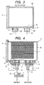
- FIG. 4 shows a purge system according to an embodiment of the present invention in the same manner as that of FIG. 6.
- the same structures as those shown in FIGS. 6 and 1 and the like are denoted by identical reference symbols for description.
- a pod 2 includes recesses 5, an inlet port 7, and an outlet port 9 at a bottom surface thereof. Further, the surface of a table 53 on which the pod 2 is placed is equipped with positioning pins 12 that are fitted into the recesses 5 to regulate the placement position of the pod 2, a table side inlet port 14 that constitutes the inlet system in association with the inlet port 7 at the pod 2 side, and a table side outlet port 16 that constitutes the outlet system in association with the outlet port 9 at the pod 2 side. Further, a toric sealing member 18 is disposed between the inlet port 7 and the table side inlet port 14 facing each other to enhance the air-tightness with respect to the exterior of the pod 2 of the inlet system.
- No sealing member 18 is disposed between the outlet port 9 and the table side outlet port 16, and a communication space 21 having an interval that substantially corresponds to the sealing member 18 is formed between those ports when the positional relationship between the pod 2 and the table 53 is determined according to the recesses 5, the positioning pins 12, the inlet system, and the like.
- Filter members 11 are disposed in the vicinity of the opening portions of the inlet and outlet ports 7 and 9 at the pod side so as to prevent dusts and the like from entering the interior of the pod 2 through the ports. Further, an upstream side of the table side inlet port 14 and a downstream side of the table side outlet port 16 in the gas flow are connected to a replacement gas inlet source and a replacement gas outlet source (not shown) which are external devices through a check valve and a flow meter (not shown), respectively. Further, in this embodiment, a flow controller 27 is disposed upstream of the table side inlet port 14 so as to control the flow rate of gas that is supplied to the interior of the pod 2.
- the semiconductor wafer 1 is contained in the interior of the pod 2, and the pod 2 having the interior tightly closed by a cover 4 is transported above the table 53.
- the pod 2 is mounted on the table 53 in a state where the positioning pins 12 that project from the table 53 are substantially fitted into the recesses 5 that are disposed on the lower portion of the pod 2.
- the inlet port 7 at the pod side is abutted against the table side inlet port 14 that is disposed on the table 53 through the sealing member 18.
- the outlet port 9 and the table side outlet port 16 face each other to form the communication space 21 therebetween.
- the inlet system and the outlet system are connected to the replacement gas supply source and the replacement gas discharge source, respectively.
- the flow rate of gas inlet for purging is set by the flow controller 27 in advance.
- the gas for purging is sucked to the interior of the pod 2, and the gas within the pod 2 is discharged.
- the magnitude of the replacement gas discharge source is set to be large, the sufficiently large gas discharge is conducted as compared with the gas suction, to thereby suppress the step-up of the internal pressure within the pod 2 due to the gas suction.
- the atmosphere is replenished through the communication space 21 to prevent the internal pressure of the interior of the pod 2 from being reduced.
- the purge operation within the pod 2 is conducted.
- the replacement gas is circulated in the stated order of the table side inlet port 14, the sealing member 20, the inlet port 7 at the pod 2 side, the filter 11, the interior of the pod 2, the filter 11, the outlet port 9 at the pod 2 side, and the table side outlet port 16, to thereby replace the atmosphere within the pod 2.
- the table 53 in which the inlet port and the outlet port are formed by one system, respectively, and the pod 2 corresponding to the table 53.
- the configuration to which the present invention is applicable is not limited to the above structure, but it is preferable that the numbers of inlet ports and outlet ports be appropriately increased or decreased taking into consideration the demanded gas replacement speed, the capacity of the pod 2, and the like.
- the present system is applied to the FOUP, but the embodiment of the present invention is not limited to the above system.
- the system according to the present invention can be applied to a system having a container that receives a plurality of objects to be held (products) therein, and a transport chamber that transports the object to be held from the container to a device that processes the object to be held, in which the atmosphere within the container is purged.
Applications Claiming Priority (1)
| Application Number | Priority Date | Filing Date | Title |
|---|---|---|---|
| JP2005184788A JP3983254B2 (ja) | 2005-06-24 | 2005-06-24 | 製品収容容器用パージシステム及び該パージシステムに供せられる台 |
Publications (2)
| Publication Number | Publication Date |
|---|---|
| EP1737030A1 true EP1737030A1 (de) | 2006-12-27 |
| EP1737030B1 EP1737030B1 (de) | 2011-01-26 |
Family
ID=36968992
Family Applications (1)
| Application Number | Title | Priority Date | Filing Date |
|---|---|---|---|
| EP06012638A Active EP1737030B1 (de) | 2005-06-24 | 2006-06-20 | Ein Reingungssystem für einen Produktbehälter und ein Tisch in Verwendung in einem Reinigungssystem |
Country Status (6)
| Country | Link |
|---|---|
| US (1) | US20060288664A1 (de) |
| EP (1) | EP1737030B1 (de) |
| JP (1) | JP3983254B2 (de) |
| KR (1) | KR100799415B1 (de) |
| DE (1) | DE602006019798D1 (de) |
| TW (1) | TWI297925B (de) |
Families Citing this family (30)
| Publication number | Priority date | Publication date | Assignee | Title |
|---|---|---|---|---|
| JP4670808B2 (ja) * | 2006-12-22 | 2011-04-13 | ムラテックオートメーション株式会社 | コンテナの搬送システム及び測定用コンテナ |
| US20100051501A1 (en) * | 2008-08-29 | 2010-03-04 | International Business Machines Corporation | Ic waper carrier sealed from ambient atmosphere during transportation from one process to the next |
| JP5155848B2 (ja) * | 2008-12-18 | 2013-03-06 | 日本ケンブリッジフィルター株式会社 | Foup用n2パージ装置 |
| JP5410794B2 (ja) * | 2009-03-17 | 2014-02-05 | 東京エレクトロン株式会社 | 基板処理装置 |
| JP2011187539A (ja) * | 2010-03-05 | 2011-09-22 | Sinfonia Technology Co Ltd | ガス注入装置、ガス排出装置、ガス注入方法及びガス排出方法 |
| SG194439A1 (en) * | 2011-05-25 | 2013-12-30 | Murata Machinery Ltd | Load port apparatus, carrier system, and container conveyance method |
| JP5887719B2 (ja) * | 2011-05-31 | 2016-03-16 | シンフォニアテクノロジー株式会社 | パージ装置、ロードポート、ボトムパージノズル本体、ボトムパージユニット |
| WO2013001482A1 (en) | 2011-06-28 | 2013-01-03 | Dynamic Micro Systems | Semiconductor stocker systems and methods. |
| JP5557061B2 (ja) * | 2012-01-04 | 2014-07-23 | 株式会社ダイフク | 物品保管設備 |
| JP6131534B2 (ja) | 2012-06-11 | 2017-05-24 | シンフォニアテクノロジー株式会社 | パージノズルユニット、ロードポート、載置台、ストッカー |
| JP6179518B2 (ja) * | 2012-08-27 | 2017-08-16 | 三菱瓦斯化学株式会社 | 粒状物の包装方法、及び、粒状物包装装置 |
| JP2014072321A (ja) * | 2012-09-28 | 2014-04-21 | Hitachi High-Technologies Corp | 板状体保持機構、基板貼り合わせ装置及び基板貼り合わせ方法 |
| KR101418812B1 (ko) * | 2012-10-31 | 2014-07-16 | 크린팩토메이션 주식회사 | 웨이퍼 퍼지 가능한 천장 보관 장치 |
| KR101398440B1 (ko) * | 2012-11-21 | 2014-06-19 | 주식회사 케이씨텍 | 풉 퍼지장치 및 이를 포함하는 기판처리장치 |
| JP5874691B2 (ja) * | 2013-06-26 | 2016-03-02 | 株式会社ダイフク | 不活性気体供給設備 |
| US9460949B2 (en) * | 2013-10-11 | 2016-10-04 | Taiwan Semiconductor Manufacturing Company Limited | Ultra-low oxygen and humility loadport and stocker system |
| US9837293B2 (en) * | 2013-10-30 | 2017-12-05 | Taiwan Semiconductor Manufacturing Co., Ltd. | Mechanisms for charging gas into cassette pod |
| KR101465644B1 (ko) * | 2013-11-27 | 2014-11-28 | 크린팩토메이션 주식회사 | 웨이퍼 수용 용기를 지지하기 위한 선반 및 그에 사용되는 캡 조립체 |
| US10325794B2 (en) | 2014-04-28 | 2019-06-18 | Murata Machinery, Ltd. | Purge device and purge method |
| JP6455261B2 (ja) * | 2015-03-20 | 2019-01-23 | シンフォニアテクノロジー株式会社 | ノズルの先端構造、パージ装置およびロードポート |
| JP6554872B2 (ja) * | 2015-03-31 | 2019-08-07 | Tdk株式会社 | ガスパージ装置、ロードポート装置、パージ対象容器の設置台およびガスパージ方法 |
| JP6451453B2 (ja) * | 2015-03-31 | 2019-01-16 | Tdk株式会社 | ガスパージ装置、ロードポート装置、パージ対象容器の設置台およびガスパージ方法 |
| TWI567856B (zh) * | 2015-09-08 | 2017-01-21 | 古震維 | 具有吹淨功能的晶圓傳送裝置 |
| JP2017108049A (ja) * | 2015-12-11 | 2017-06-15 | Tdk株式会社 | Efemにおけるウエハ搬送部及びロードポート部の制御方法 |
| DE102016205597B4 (de) * | 2016-04-05 | 2022-06-23 | Fabmatics Gmbh | Purge-Messsystem für FOUPs |
| JP6269788B2 (ja) * | 2016-11-22 | 2018-01-31 | シンフォニアテクノロジー株式会社 | ロードポート |
| US11139188B2 (en) * | 2017-04-28 | 2021-10-05 | Sinfonia Technology Co., Ltd. | Gas supply device, method for controlling gas supply device, load port, and semiconductor manufacturing apparatus |
| JP2018074177A (ja) * | 2017-12-26 | 2018-05-10 | シンフォニアテクノロジー株式会社 | ロードポート |
| CN111354665B (zh) * | 2018-12-20 | 2023-05-02 | 夏泰鑫半导体(青岛)有限公司 | 晶圆存储装置及半导体加工设备 |
| JP7422577B2 (ja) * | 2020-03-23 | 2024-01-26 | 平田機工株式会社 | ロードポート及び制御方法 |
Citations (4)
| Publication number | Priority date | Publication date | Assignee | Title |
|---|---|---|---|---|
| US6199604B1 (en) * | 1997-10-13 | 2001-03-13 | Tdk Corporation | Clean box, clean transfer method and apparatus therefor |
| US20010042439A1 (en) * | 1996-09-13 | 2001-11-22 | Roberson Glenn A. | Molecular contamination control system |
| US6430802B1 (en) * | 1997-11-17 | 2002-08-13 | Tdk Corporation | Clean box, clean transfer method and apparatus therefor |
| US20040237244A1 (en) * | 2003-05-26 | 2004-12-02 | Tdk Corporation | Purge system for product container and interface seal used in the system |
Family Cites Families (10)
| Publication number | Priority date | Publication date | Assignee | Title |
|---|---|---|---|---|
| JPH0748004A (ja) * | 1993-08-04 | 1995-02-21 | Dainippon Screen Mfg Co Ltd | 基板保持容器およびこの容器を用いる基板処理装置 |
| JP3617681B2 (ja) * | 1995-01-24 | 2005-02-09 | アシスト シンコー株式会社 | 可搬式密閉コンテナのガス供給システム |
| US6164664A (en) * | 1998-03-27 | 2000-12-26 | Asyst Technologies, Inc. | Kinematic coupling compatible passive interface seal |
| US5988233A (en) * | 1998-03-27 | 1999-11-23 | Asyst Technologies, Inc. | Evacuation-driven SMIF pod purge system |
| JP3367421B2 (ja) * | 1998-04-16 | 2003-01-14 | 東京エレクトロン株式会社 | 被処理体の収納装置及び搬出入ステージ |
| US6187182B1 (en) * | 1998-07-31 | 2001-02-13 | Semifab Incorporated | Filter cartridge assembly for a gas purging system |
| US6056026A (en) * | 1998-12-01 | 2000-05-02 | Asyst Technologies, Inc. | Passively activated valve for carrier purging |
| JP2003017553A (ja) * | 2001-06-29 | 2003-01-17 | Semiconductor Leading Edge Technologies Inc | 基板収納容器、基板搬送システム及びガス置換方法 |
| JP2003092345A (ja) * | 2001-07-13 | 2003-03-28 | Semiconductor Leading Edge Technologies Inc | 基板収納容器、基板搬送システム、保管装置及びガス置換方法 |
| JP2004345715A (ja) * | 2003-05-26 | 2004-12-09 | Tdk Corp | 製品収容容器用パージシステム |
-
2005
- 2005-06-24 JP JP2005184788A patent/JP3983254B2/ja active Active
-
2006
- 2006-06-16 US US11/424,752 patent/US20060288664A1/en not_active Abandoned
- 2006-06-19 TW TW095121949A patent/TWI297925B/zh active
- 2006-06-20 EP EP06012638A patent/EP1737030B1/de active Active
- 2006-06-20 DE DE602006019798T patent/DE602006019798D1/de active Active
- 2006-06-23 KR KR1020060056663A patent/KR100799415B1/ko active IP Right Grant
Patent Citations (4)
| Publication number | Priority date | Publication date | Assignee | Title |
|---|---|---|---|---|
| US20010042439A1 (en) * | 1996-09-13 | 2001-11-22 | Roberson Glenn A. | Molecular contamination control system |
| US6199604B1 (en) * | 1997-10-13 | 2001-03-13 | Tdk Corporation | Clean box, clean transfer method and apparatus therefor |
| US6430802B1 (en) * | 1997-11-17 | 2002-08-13 | Tdk Corporation | Clean box, clean transfer method and apparatus therefor |
| US20040237244A1 (en) * | 2003-05-26 | 2004-12-02 | Tdk Corporation | Purge system for product container and interface seal used in the system |
Also Published As
| Publication number | Publication date |
|---|---|
| KR100799415B1 (ko) | 2008-01-30 |
| US20060288664A1 (en) | 2006-12-28 |
| EP1737030B1 (de) | 2011-01-26 |
| JP2007005604A (ja) | 2007-01-11 |
| TW200709329A (en) | 2007-03-01 |
| JP3983254B2 (ja) | 2007-09-26 |
| DE602006019798D1 (de) | 2011-03-10 |
| TWI297925B (en) | 2008-06-11 |
| KR20060135536A (ko) | 2006-12-29 |
Similar Documents
| Publication | Publication Date | Title |
|---|---|---|
| EP1737030B1 (de) | Ein Reingungssystem für einen Produktbehälter und ein Tisch in Verwendung in einem Reinigungssystem | |
| JP7445162B2 (ja) | ドア開閉システムおよびドア開閉システムを備えたロードポート | |
| JP6349750B2 (ja) | Efem | |
| JP6556148B2 (ja) | ロードポート及びロードポートの雰囲気置換方法 | |
| US11328938B2 (en) | Substrate processing apparatus and methods with factory interface chamber filter purge | |
| JP7193748B2 (ja) | ロードポート | |
| JP4251580B1 (ja) | 被収容物搬送システム | |
| KR101220790B1 (ko) | 진공 처리 장치, 진공 처리 장치의 운전 방법 및 기억 매체 | |
| US20150228516A1 (en) | Apparatus and operation method thereof | |
| US20150235885A1 (en) | Purge system, pod used with purge system, and load port apparatus | |
| JP6583482B2 (ja) | Efem | |
| TW201943007A (zh) | 裝載端口以及設備前端模組 | |
| JP6853489B2 (ja) | Efem | |
| JP4414869B2 (ja) | 真空処理装置 | |
| KR20230111298A (ko) | Efem의 기류 안정화 배기장치 및 이를 구비한 반도체 공정장치 | |
| WO2014041656A1 (ja) | 真空処理装置 | |
| JP2002373927A (ja) | 防塵機能を備えた半導体ウェーハ処理装置 |
Legal Events
| Date | Code | Title | Description |
|---|---|---|---|
| PUAI | Public reference made under article 153(3) epc to a published international application that has entered the european phase |
Free format text: ORIGINAL CODE: 0009012 |
|
| AK | Designated contracting states |
Kind code of ref document: A1 Designated state(s): AT BE BG CH CY CZ DE DK EE ES FI FR GB GR HU IE IS IT LI LT LU LV MC NL PL PT RO SE SI SK TR |
|
| AX | Request for extension of the european patent |
Extension state: AL BA HR MK YU |
|
| 17P | Request for examination filed |
Effective date: 20070622 |
|
| AKX | Designation fees paid |
Designated state(s): DE FR |
|
| 17Q | First examination report despatched |
Effective date: 20071001 |
|
| GRAP | Despatch of communication of intention to grant a patent |
Free format text: ORIGINAL CODE: EPIDOSNIGR1 |
|
| GRAS | Grant fee paid |
Free format text: ORIGINAL CODE: EPIDOSNIGR3 |
|
| GRAA | (expected) grant |
Free format text: ORIGINAL CODE: 0009210 |
|
| AK | Designated contracting states |
Kind code of ref document: B1 Designated state(s): DE FR |
|
| REF | Corresponds to: |
Ref document number: 602006019798 Country of ref document: DE Date of ref document: 20110310 Kind code of ref document: P |
|
| REG | Reference to a national code |
Ref country code: DE Ref legal event code: R096 Ref document number: 602006019798 Country of ref document: DE Effective date: 20110310 |
|
| PLBE | No opposition filed within time limit |
Free format text: ORIGINAL CODE: 0009261 |
|
| STAA | Information on the status of an ep patent application or granted ep patent |
Free format text: STATUS: NO OPPOSITION FILED WITHIN TIME LIMIT |
|
| 26N | No opposition filed |
Effective date: 20111027 |
|
| REG | Reference to a national code |
Ref country code: DE Ref legal event code: R097 Ref document number: 602006019798 Country of ref document: DE Effective date: 20111027 |
|
| REG | Reference to a national code |
Ref country code: FR Ref legal event code: ST Effective date: 20120229 |
|
| PG25 | Lapsed in a contracting state [announced via postgrant information from national office to epo] |
Ref country code: FR Free format text: LAPSE BECAUSE OF NON-PAYMENT OF DUE FEES Effective date: 20110630 |
|
| PGFP | Annual fee paid to national office [announced via postgrant information from national office to epo] |
Ref country code: DE Payment date: 20230502 Year of fee payment: 18 |